pertanika j. sci. & technol. 21 (1): 625 - 634 (2013...
TRANSCRIPT

Pertanika J. Sci. & Technol. 21 (1): 625 - 634 (2013)
SCIENCE & TECHNOLOGYJournal homepage: http://www.pertanika.upm.edu.my/
ISSN: 0128-7680 © 2013 Universiti Putra Malaysia Press.
INTRODUCTION
Peat represents the extreme form of soft soil. It is an organic soil which consists more than 70% of organic matters. Peat deposits are
A Numerical Study of Ground Improvement Technique Using Group of Soil-Column on Peat
Muntohar, A. S.1*, Rahman, M. E.1, Hashim, R.2 and Islam, M. S.3
1Department of Civil & Construction Engineering, Curtin University, Sarawak Campus, 98009 Miri, Sarawak, Malaysia2Department of Civil Engineering, Faculty of Engineering, Universiti Malaya, Kuala Lumpur, Malaysia3Postgraduate Student, Department of Civil Engineering, Monash University , Clayton Campus, Wellington Road, Clayton, Victoria 3800, Australia
ABSTRACT
The importance of numerical analysis in investigation of piled embankment over soft soil has been developed since 1990. Several investigators have extended the numerical analysis to model ground improvement using soil-column to support embankment or structures. This paper presents a numerical analysis of the Pulverized Fuel Ash (PFA) column-treated peat and compared with field static-loading test results. Back analysis was performed to determine the material parameters and soil stiffness surrounding soil & soil-column. Two geometrical models were used in this analysis: (a) block (Model A), and (b) column group (Model B). This situation was analyzed using commercially available finite element package PLAXIS 2D ver. 8.2. It is found that both models are reliable to simulate the field static-loading test for column-treated peat. Model B shows a higher stability to failure if compared to Model A.
Keywords: Peat, load-settlement curve, PFA column, FEM
Article history:Received: 29 February 2012Accepted: 15 March 2012
E-mail addresses: [email protected] (Muntohar, A. S.), [email protected] (Rahman, M. E.), [email protected] (Hashim, R.), [email protected] (Islam, M. S.)*Corresponding Author
found where conditions are favourable for their formation. In Malaysia, three million hectares of land is covered with peat. While in Indonesia, peat covers about 26 million hectares of the country land area. Two third of the world coverage of tropical peat are in South East Asia. Since the coverage of peat is quite extensive, utilization of marginal soil has been required in recent years. Hence, suitable geotechnical design parameters and construction techniques are needed for this type of ground condition. Peat poses serious
Muntohar, A. S., Rahman, M. E., Hashim, R. and Islam, M. S.
626 Pertanika J. Sci. & Technol. 21 (1): 625 - 634 (2013)
problems in construction due to its long-term consolidation settlements even when subjected to a moderate load (Jarret, 1995). Under such circumstances, deep soil stabilization technique is often an economically attractive alternative to removal of deep peat or use of piles as deep foundation. As the cost of conventional reinforced concrete piles continue to increase, economical deep soil stabilization has become a viable solution to deep peat improvement. The essential feature of deep soil stabilization is that columns of ‘stabilized’ material are formed by mixing the soil in place with a ‘binder’ and the interaction of the binder with the soft soil leads to a material which has better engineering properties than the original soil (Hebib & Farrell, 2003).
Research findings indicated that the engineering properties of peat soil can be improved by including binders such as ordinary Portland and rapid setting PFA cement, ground granulated furnace slag, bentonite and etc (Ahnberg, 2006; Hashim & Islam, 2008; Sing et al., 2009). One of the major requirements for the safe and economic design of a foundation is the determination of ultimate bearing capacity. This is a maximum load that can be applied to subgrade soil from the foundation without the occurrence of shear or punching failure, keeping settlement to a limited range and avoiding serviceability damage to superstructure (Eslami & Gholami, 2006).
In recent decades, numerical analysis such as finite element method with the support of computer technology has been increasingly applied in the geotechnical engineering. The importance of numerical analysis in investigation of piled embankment over soft soil has been developed since 1990 (Jones et al., 1990; Russel & Pierpoint, 1997; Jenck et al., 2007). Several investigators have extended the numerical analysis to model ground improvement using soil-column to support embankment or structures (Chai & Miura, 2003; Han et al., 2007; Islam & Hashim, 2010). Nowadays, numerical analysis is strongly recommended, especially for detailed designs. This paper aims to evaluate the soil and soil-column parameters by back calculation using numerical method based on field static loading test.
NUMERICAL MODELING
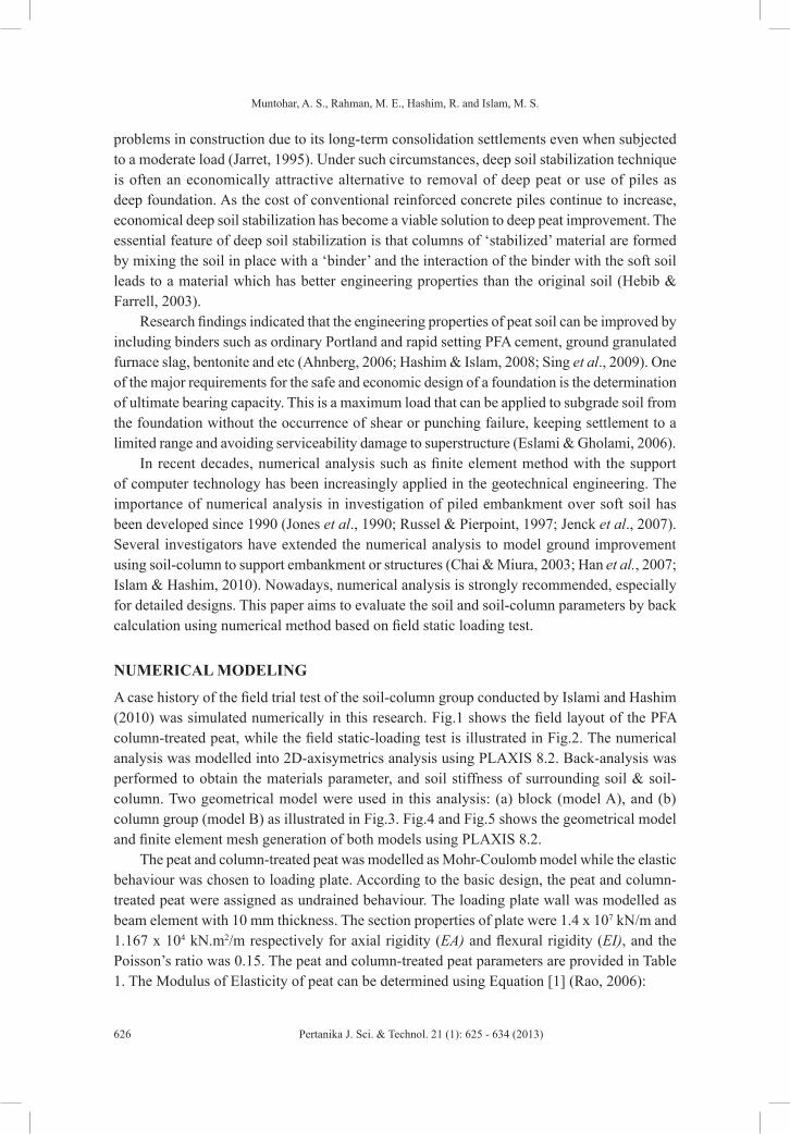
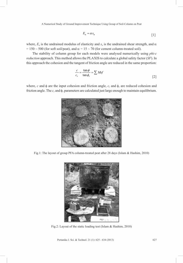
A case history of the field trial test of the soil-column group conducted by Islami and Hashim (2010) was simulated numerically in this research. Fig.1 shows the field layout of the PFA column-treated peat, while the field static-loading test is illustrated in Fig.2. The numerical analysis was modelled into 2D-axisymetrics analysis using PLAXIS 8.2. Back-analysis was performed to obtain the materials parameter, and soil stiffness of surrounding soil & soil-column. Two geometrical model were used in this analysis: (a) block (model A), and (b) column group (model B) as illustrated in Fig.3. Fig.4 and Fig.5 shows the geometrical model and finite element mesh generation of both models using PLAXIS 8.2.
The peat and column-treated peat was modelled as Mohr-Coulomb model while the elastic behaviour was chosen to loading plate. According to the basic design, the peat and column-treated peat were assigned as undrained behaviour. The loading plate wall was modelled as beam element with 10 mm thickness. The section properties of plate were 1.4 x 10⁷ kN/m and 1.167 x 10⁴ kN.m2/m respectively for axial rigidity (EA) and flexural rigidity (EI), and the Poisson’s ratio was 0.15. The peat and column-treated peat parameters are provided in Table 1. The Modulus of Elasticity of peat can be determined using Equation [1] (Rao, 2006):
A Numerical Study of Ground Improvement Technique Using Group of Soil-Column on Peat
627Pertanika J. Sci. & Technol. 21 (1): 625 - 634 (2013)
u uE sα= [1]
where, Eu is the undrained modulus of elasticity and su is the undrained shear strength, and α = 150 ~ 500 (for soft soil/peat), and α = 15 ~ 70 (for cement column-treated soil).
The stability of column group for each models were analysed numerically using phi-c reduction approach. This method allows the PLAXIS to calculate a global safety factor (SF). In this approach the cohesion and the tangent of friction angle are reduced in the same proportion:
tantanr r
c Msfc
φφ
= = ∑ [2]
where, c and φ are the input cohesion and friction angle, cr and φr are reduced cohesion and friction angle. The cr and φr parameters are calculated just large enough to maintain equilibrium.
Fig.1: The layout of group PFA column-treated peat after 28 days (Islam & Hashim, 2010)
Fig.2: Layout of the static loading test (Islam & Hashim, 2010)

Muntohar, A. S., Rahman, M. E., Hashim, R. and Islam, M. S.
628 Pertanika J. Sci. & Technol. 21 (1): 625 - 634 (2013)
(a) (b)
1m
Applied Load
Column,= 0.2 m
0.5 m
Plate, t = 10mm
Influencedzone 1
m
0.7 m
Applied LoadPlate, t = 10
mm
Treated peat
Untreated peat
(a) (b)
Fig.3: The modeling of column-treated peat (a) block model (model A), (b) column group (model B)
(a) (b)
Fig.4: (a) Formation of group column modelling for computer simulations Model A, (b) Finite elemenet mesh generation.
(a) (b)
Fig.5: (a) Formation of group column modelling for computer simulations Model B, (b) Finite elemenet mesh generation

A Numerical Study of Ground Improvement Technique Using Group of Soil-Column on Peat
629Pertanika J. Sci. & Technol. 21 (1): 625 - 634 (2013)
TABLE 1 Material parameters used in computer modelling
Materials Typeγd
(kN/m3)γsat
(kN/m3)kx
(m/s)ky
(m/s)ν Eu
(kPa)c
(kPa)φ
(_o)Peat Undrained 8.21 10.02 4.46 x 10⁻⁹ 2.23 x 10⁻⁹ 0.35 2350 4.7 24
Prebored-premixed column
Undrained 20.9 23 4.1 x 10⁻¹² 4.1 x 10⁻¹² 0.25 18900 378 55
Mixing auger column Undrained 18. 20.34 4.1 x 10⁻¹² 4.1 x 10⁻¹² 0.25 3855 257 40
Influence zone Undrained 8.21 10.02 4.1 x 10⁻¹² 4.1 x 10⁻¹² 0.35 1927.5 129 30
RESULTS AND DISCUSSION
Load-settlement curves
The load-settlement curves of the group columns using prebored–premixed (PPM) and mixing auger method (MAM) are presented in Fig.6(a) and Fig.6(b) respectively. The Fig.6(a) and Fig.6(b) compare the load-settlement curve of finite element analysis and field static loading test results. The field load-settlement curves were obtained from Islam and Hashim (2010). It is observed that the group column using PPM experienced less settlement if compared with MAM. It indicated that PPM exhibits a higher stiffness than MAM. It is observed that settlement increased steadily due to the increment of applied load. The final settlement after 30 kN applied load was about 13.8 mm and 17.5 mm respectively for the PPM and MAM group column. Different behaviours were exhibited by PPM and MAM group column. It can be seen in the Fig.6(a) and Fig.6(b) that an elasto-plastic behaviour was exhibited by PPM group columns and elastic behaviour was exhibited by MAM group columns respectively.
Applied Load (kN)
0 5 10 15 20 25 30
Settl
emen
t, (m
m)
0
5
10
15
20
25
Field testFEM: Model AFEM: Model B
Applied Load (kN)
0 5 10 15 20 25 30
Settl
emen
t, (m
m)
0
2
4
6
8
10
12
14
Field testFEM: Model AFEM: Model B
(a) (b)
Fig.6: Load – settlement curve for (a) prebored-premixed method, and (b) mixing-auger method

Muntohar, A. S., Rahman, M. E., Hashim, R. and Islam, M. S.
630 Pertanika J. Sci. & Technol. 21 (1): 625 - 634 (2013)
The comparison of load-settlement curves of finite element method and static load test for the group peat-columns shows that Model A and Model B has a similar trend of gradual increment of settlement due to the increase of applied load. For PPM column, modelling the group column as block (Model A) shows a similar pattern of the load-settlement curve with the field test (Fig.6a) and the results obtained from numerical analysis are closer to the results obtained from field test. For MAM column, the group column model (Model B) is showing similar pattern of the load-settlement curve obtained from field test (Fig.6b). But, the settlements are slight higher than the field test except at 30 kN applied load. An analysis conducted by Islam and Hashim (2010) showed a quite different load-settlement curve between the finite element model and field loading test. Hence, the results obtained in this study improve the numerical analysis conducted in previous research. The simulation results in this study shows that elasto-plastic Mohr-Coulomb model for the peat and PFA column-treated peat can be applied to model load-settlement behaviour. In both cases, the deviation between measured and computer modelling is due to the difficulties to simulate a true input parameter of each materials. During the numerical simulations, the soil deformations are much affected by soil stiffness (modulus). The stiff soil facilitates the stabilization process and reduces model deformation (Poorooshasb & Meyerhof, 1997). Moreover, anisotropic stiffness strongly influences the pore pressure development during static loading on peat (Zwanenburg & Barends, 2007). Use of the 3D finite element method and other advanced materials model such as soft soil creep model can be an alternative analysis to minimize the deviation between the computer modelling and field test (Eka, 2007; Voottipruex et al., 2011).
This study suggests the modulus of elasticity for peat, PFA column-treated peat, and the influences zone as follows:
• Peat: 500u uE s=
• Prebored-premixed column: ( ) 70 uu colE s=
• Mixing auger column: ( ) 15 uu colE s=
• Influence zone: ( ) ( )inf 0.5u u colE E=
Settlement profile and Stability to failure
Fig.7 and Fig.8 shows the settlement profile of the group column-treated peat using PPM and MAM respectively. A different settlement profiles are shown between Model A and Model B of group column. The group column assigned as Model A experiences a general shear failure, while Model B has tendency to local or punch shear failure. It is observed that maximum settlement occurs at near ground surface, and decreases with the depth. “Arching effect” was observed at the end of Model B group column (Fig.7b and Fig.8b). As consequence, this effect will reduce the settlement at the soil between the columns. Satibi (2009) mentioned that “arching effect” is due to differential settlement between stiff pile or column and the soft soil surface.
Stability of the group columns were analyzed by phi-c reduction calculation. The stability is assigned as safety factor to failure. The safety factor (SF) due to final loading (30 kN) is presented in Table 2. The block model of column (Model A) have lower safety factor to failure if compared to column group model (Model B) for both stabilization methods. This result

A Numerical Study of Ground Improvement Technique Using Group of Soil-Column on Peat
631Pertanika J. Sci. & Technol. 21 (1): 625 - 634 (2013)
indicates that the analysis of column will be in worst state if the soil-column failure is assumed as block failure. Brooms (1991) stated that the bearing capacity of a group of columns arises from the skin resistance along the perimeter of the column group and the base resistance of the block. According to this approach, modelling the group column as Model B will have longer perimeter, and produce a higher skin resistance. As a result, the column group can retain a high applied load. Hence, the stability to failure increases.
TABLE 2 Safety factor to failure at final loading (30 kN)
Stabilization Method Computer Model Safety Factor
Prebored-premixed columnModel A 1.25Model B 1.66
Mixing auger columnModel A 1.29Model B 1.88
Fig.7: Settlement profile of the PPM column (a) Model A, (b) Model B at final loading test (30 kN)

Muntohar, A. S., Rahman, M. E., Hashim, R. and Islam, M. S.
632 Pertanika J. Sci. & Technol. 21 (1): 625 - 634 (2013)
CONCLUSION
The findings of this research will advance the knowledge on the load-settlement behaviour of the stabilized-peat using soil-cement column and chemical admixture. Modelling the group column as Model A and Model B has a similar trend of gradual increment of settlement due to the increase of applied load. For PPM column, modelling the group column as block (Model A) shows a similar pattern of the load-settlement curve with the field test. For MAM column, the group column model (Model B) was showing similar pattern of the load-settlement curve obtained from field test.
The results obtained in this study improve the numerical analysis conducted in previous research findings. The simulation results in this study shows that elasto-plastic Mohr-Coulomb model for the peat and PFA column-treated peat can be applied to model load-settlement behaviour. The group column assigned as Model A experiences a general shear failure, while
Fig.8: Settlement profile of the PPM column (a) Model A, (b) Model B at final loading test (30 kN)
A Numerical Study of Ground Improvement Technique Using Group of Soil-Column on Peat
633Pertanika J. Sci. & Technol. 21 (1): 625 - 634 (2013)
Model B has tendency to local or punch shear failure. The block model of column (Model A) have lower safety factor to failure if compared to column group model (Model B) for both stabilization methods. Whole results in this study show that the models and estimated materials parameter using equation [1] are reliable to model load-settlement using finite element method.
ACKNOWLEDGEMENTS
The first Author is grateful to the R&D Department, Curtin University Sarawak for financial support to conduct this research work under CSRF scheme.
REFERENCESAhnberg, H. (2006). Strength of Stabilized Soils: A laboratory study on clays and organic soils stabilized
with different types of binder. In the 16th Report of Swedish Deep Stabilization Research Centre, Linkoping, Sweden.
Broms, B. B. (1991). Stabilization of Soil with Lime Columns. In Fang, H-Y. & van Nostrand, R. (Eds). Foundation Engineering Handbook, 2nd Edition. New York. pp. 833-855.
Chai, J. C., & Miura, N. (2003, October). Effect of soil-cement column construction to surrounding subsoil. In the Proceeding of Geotechnical Engineering in Urban Construction. Sino-Japanese Symp. Geotech. Engrg., Beijing, China, pp. 96-101, 29-30 October 2003.
Eka, P. (2007). Behaviour of Tiang Tongkat foundation over Pontianak soft organic soil using 3D–finite element analysis. (Doctoral thesis dissertation). Technischen Universität Bergakademie Freiberg, Germany, 2007.
Eslami, A., & Gholami, M. (2006). Analytical model for the ultimate bearing capacity of foundations from cone resistance. Scientia Iranica, 13, 223-233.
Han, J., Oztoprak, S., Parsons, R. L., & Huang, J. (2007). Numerical analysis of foundation columns to support widening of embankments. Computers and Geotechnics, 34(6), 435-448.
Hashim, R., & Islam, S. (2008). Properties of stabilized peat by soil-cement column method. Elec. J. Geotech. Engrg. 13(J), 1-8.
Hebib, S., & Farrell, E. R. (2003). Some experiences on the stabilization of Irish peats. Canadian Geotechnical Journal, 40(1), 107-120.
Islam, M. S., & Hashim,R. (2010). Stabilization of peat soil by soil-column technique and settlement of the group columns. Int. J Physical Sci., 5(9), 1411-1418.
Jarret, P. M. (1995). Geoguide 6, site investigation for organics soils and peat (JKR Document 20709-0341-95). Institut Kerja Raya Malaysia, 1995.
Jenck, O., Dias, D., & Kastner, R. (2007). Two-Dimensional Physical and Numerical Modeling of a Pile-Supported Earth Platform over Soft Soil. Journal of Geotechnical and Geoenvironmental Engineering, 133(3), 295-305.
Jones, C. J. F. P., Lawson, C. R., & Ayres, D. J. (1990). Geotextile reinforced piled embankment. In the Proceeding of 4th Int. Conf. on Geotex., Geomembranes and Related Products, Vol 1, The Haque, A.A. Balkema, pp. 155-160.

Muntohar, A. S., Rahman, M. E., Hashim, R. and Islam, M. S.
634 Pertanika J. Sci. & Technol. 21 (1): 625 - 634 (2013)
Poorooshasb, H. B., & Meyerhof, G. G. (1997). Analysis of behavior of stone columns and lime columns. Computers and Geotechnics, 20(1), 47-70.
Rao, K. N. (2006). Numerical modeling and analysis of pile supported embankments. (MS Thesis dissertation). University of Texas at Arlington, USA, 2006.
Russel, D., & Pierpoint, N. (1997). Assessment of design methods for piled embankment. Ground Engrg., 30(10), 39-49.
Satibi, S. (2009). Numerical analysis and design criteria of embankments on floating piles. (Doctoral thesis dissertation). Instituts für Geotechnik Universität Stuttgart, Germany, 2009.
Sing, W. L., Hashim, R., & Ali, F. H. (2009). Unconfined compressive strength of cemented peat. Aust. J Basic App. Sci., 3(4), 3850-3856.
Voottipruex, P., Suksawat, T., Bergado, D. T., & Jamsawang, P. (2011). Numerical simulations and parametric study of SDCM and DCM piles under full scale axial and lateral loads. Computers and Geotechnics, 38(3), 318-329.
Zwanenburg, C, & Barends, F. B. J. (2007). The influences of anisotropic stiffness on the consolidation of peat. Soil Found., 47(3), 507-516.