perry nuclear, unit 1 - submission of core operating
TRANSCRIPT
FENOC FirstEnergy Nuclear Operating Con7pany
Perry Nuclear Power Plant 10 Center Road
Perry, Ohio 44081
John K. Wood 440-280-5224 Vice President, Nuclear Fax: 440-280-8029
June 14, 2000 PY-CEI/NRR-2504L
United States Nuclear Regulatory Commission Document Control Desk Washington, D.C. 20555
Perry Nuclear Power Plant Docket No. 50-440 Submission of Core Operating Limits Report
Ladies and Gentlemen:
Enclosed is a copy of the revised Cycle 8 Core Operating Limits Report (COLR) for Unit 1 of the Perry Nuclear Power Plant (PNPP). The revision to the COLR was necessitated by the implementation of a recently approved license amendment (License Amendment 112, dated June 1, 2000) which authorized the PNPP to operate at a higher thermal power. The COLR is submitted in accordance with Technical Specification Section 5.6.5, "Core Operating Limits Report."
Due to three fuel bundles being replaced during a mid-cycle outage, the as-loaded core is slightly different than the core reference loading pattern described in the Supplemental Reload Licensing Report for Cycle 8. The as-loaded core was re-evaluated using the methodology contained in "General Electric Standard Application for Reactor Fuel" (GESTAR II). The results of the evaluation show that the as-loaded core satisfies the requirements of GESTAR I1. Therefore, the Supplemental Reload Licensing Report remains bounding.
If you have questions or require additional information, please contact Mr. Gregory A. Dunn, Manager - Regulatory Affairs, at (440) 280-55305.
cc: NRC Project Manager NRC Resident Inspector NRC Region III
%VOo

PDB-FOO01 Page: i Rev.: 7
PERRY OPERATIONS MANUAL
Plant Data Book Entry
TITLE: CORE OPERATING LIMITS REPORT FOR THE PERRY NUCLEAR POWER PLANT UNIT 1
CYCLE 8 (RELOAD 7) Power Uprate
PDB - F0001 /Rev. 7 MPL: Jll EFFECTIVE DATE: ýo- /1q-&
SUMMARY OF LAST CHANGE: Periodic Review - Not Required
This incorporates the core thermal limits for Cycle 8. Power Uprate.
REFERENCES: PY-CEI-NRR-1104 L; PY-CEI-NRR-1157 L; PY-NRR-CEI-0529;
PY-CEI-NRR-2420 L
COMMITMENTS: L01462, L01960, L02362
PREPARED BY:
REVIEWED BY:
APPROVED BY:
Patrick J. Curran
'%-esponsible Manager/Director
TAB E, F, G,
APPROVED BY:
AND R USE ONLY ��KO2e2� �ŽL2�2di
Date
PPD ,iate
6-3-00 Date
1,0 Date
PDB-FOO01 Page: i Rev.: 7
PERRY OPERATIONS MANUAL
Plant Data Book Entry
TITLE: CORE OPERATING LIMITS REPORT FOR THE PERRY NUCLEAR POWER PLANT UNIT 1
CYCLE 8 (RELOAD 7) Power Uprate
PDB - F0001 /Rev. 7 MPL: Jll EFFECTIVE DATE:
SUMMARY OF LAST CHANGE: Periodic Review - Not Required
This incorporates the core thermal limits for Cycle 8. Power UDrate.
REFERENCES: PY-CEI-NRR-1104 L; PY-CEI-NRR-1157 L; PY-NRR-CEI-0529;
PY-CEI-NRR-2420 L
COMMITMENTS: L01462, L01960, L02362
PREPARED BY: Patrick J. Curran 6-3-00 Date
EFFECTIVE PIC's
t *1
&,-j4-o
PIC Type of Effective No. Change Date

PDB-FOO01 Page: 1 Rev.: 7
UNIT 1 CORE OPERATING LIMITS REPORT
INDEX
Specification
INTRODUCTION AND REFERENCES
AVERAGE PLANAR LINEAR HEAT GENERATION RATE (CORRESPONDS TO TS 3.2.1)
Figure 3.2.1-1 Flow Dependent MAPLHGR Factor (MAPFACf),
Fuel Types GEl0
Figure 3.2.1-2 Flow Dependent MAPLHGR Factor (MAPFACf),
Fuel Types GEl1
Figure 3.2.1-2a Flow Dependent MAPLHGR Factor (MAPFACf),
Fuel Types GE12
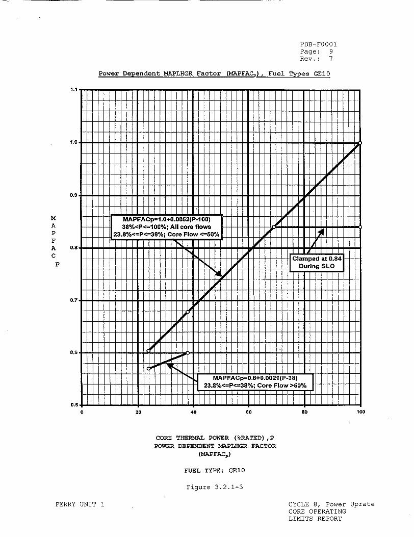
Figure 3.2.1-3 Power Dependent MAPLHGR Factor (MAPFACp),
Fuel Types GEl0
Figure 3.2.1-4 Power Dependent MAPLHGR Factor (MAPFACp),
Fuel Types GEl1
Figure 3.2.1-4a Power Dependent MAPLHGR Factor (MAPFACp),
Fuel Types GE12
Figure 3.2.1-5 MAPLHGR Versus Average Planar Exposure,
Fuel Type GE12-PI0SSB399-16GZ-120T-150-T
Figure 3.2.1-6 MAPLHGR Versus Average Planar Exposure,
Fuel Type GE12-PI0SSB399-14GZ-120T-150-T
Figure 3.2.1-7 MAPLHGR Versus Average Planar Exposure, Fuel Type GE12-P10SSB369-14GZ-120T-150-T
Figure 3.2.1-8 MAPLHGR Versus Average Planar Exposure,
Fuel Type GE12-PIOSSB369-12GZ-120T-150-T
Figure 3.2.1-9 MAPLHGR Versus Average Planar Exposure,
Fuel Type GEI1-P9SUB338-12GZ-120T-146-T
Figure 3.2.1-10 MAPLHGR Versus Average Planar Exposure,
Fuel Type GEl1-P9SUB338-10GZ-120T-146-T
Figure 3.2.1-11 MAPLHGR Versus Average Planar Exposure,
Fuel Type GE10-P8SXB306-11GZ3-120M-150-T (GE8X8NB-1)
PERRY UNIT 1 CYCLE 8, Power CORE OPERATING LIMITS REPORT
Page
3
5
6
7
8
9
10
11
12
13
14
15
16
17
18
Uprate
PDB-F0001 Page: 2 Rev.: 7
UNIT 1 CORE OPERATING LIMITS REPORT
INDEX (Continued)
Specification Page
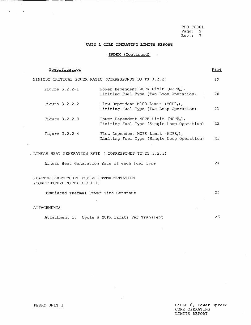
MINIMUM CRITICAL POWER RATIO (CORRESPONDS TO TS 3.2.2) 19
Figure 3.2.2-1 Power Dependent MCPR Limit (MCPRp), Limiting Fuel Type (Two Loop Operation) 20
Figure 3.2.2-2 Flow Dependent MCPR Limit (MCPRf),
Limiting Fuel Type (Two Loop Operation) 21
Figure 3.2.2-3 Power Dependent MCPR Limit (MCPRp), Limiting Fuel Type (Single Loop Operation) 22
Figure 3.2.2-4 Flow Dependent MCPR Limit (MCPRf),
Limiting Fuel Type (Single Loop Operation) 23
LINEAR HEAT GENERATION RATE ( CORRESPONDS TO TS 3.2.3)
Linear Heat Generation Rate of each Fuel Type 24
REACTOR PROTECTION SYSTEM INSTRUMENTATION
(CORRESPONDS TO TS 3.3.1.1)
Simulated Thermal Power Time Constant 25
ATTACHMENTS
Attachment 1: Cycle 8 MCPR Limits Per Transient 26
PERRY UNIT 1 CYCLE 8, Power Uprate CORE OPERATING LIMITS REPORT
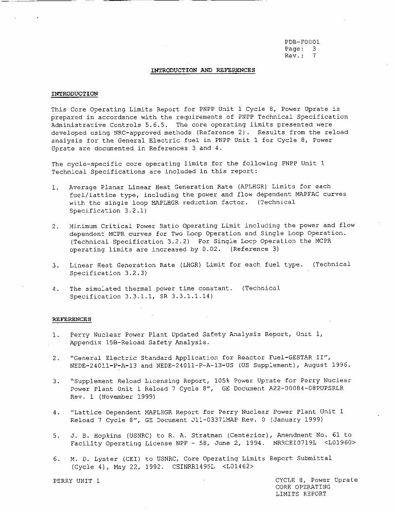
PDB-F0001 Page: 3 Rev.: 7
INTRODUCTION AND REFERENCES
INTRODUCTION
This Core Operating Limits Report for PNPP Unit 1 Cycle 8, Power Uprate is prepared in accordance with the requirements of PNPP Technical Specification Administrative Controls 5.6.5. The core operating limits presented were developed using NRC-approved methods (Reference 2). Results from the reload analysis for the General Electric fuel in PNPP Unit 1 for Cycle 8, Power Uprate are documented in References 3 and 4.
The cycle-specific core operating limits for the following PNPP Unit 1 Technical Specifications are included in this report:
1. Average Planar Linear Heat Generation Rate (APLHGR) Limits for each fuel/lattice type, including the power and flow dependent MAPFAC curves with the single loop MAPLHGR reduction factor. (Technical Specification 3.2.1)
2. Minimum Critical Power Ratio Operating Limit including the power and flow dependent MCPR curves for Two Loop Operation and Single Loop Operation. (Technical Specification 3.2.2) For Single Loop Operation the MCPR operating limits are increased by 0.02. (Reference 3)
3. Linear Heat Generation Rate (LHGR) Limit for each fuel type. (Technical Specification 3.2.3)
4. The simulated thermal power time constant. (Technical Specification 3.3.1.1, SR 3.3.1.1.14)
REFERENCES
1. Perry Nuclear Power Plant Updated Safety Analysis Report, Unit 1, Appendix 15B-Reload Safety Analysis.
2. "General Electric Standard Application for Reactor Fuel-GESTAR II", NEDE-24011-P-A-13 and NEDE-24011-P-A-13-US (US Supplement), August 1996.
3. "Supplement Reload Licensing Report, 105% Power Uprate for Perry Nuclear Power Plant Unit 1 Reload 7 Cycle 8", GE Document A22-00084-08PUPSRLR Rev. 1 (November 1999)
4. "Lattice Dependent MAPLHGR Report for Perry Nuclear Power Plant Unit 1 Reload 7 Cycle 8", GE Document Jll-03371MAP Rev. 0 (January 1999)
5. J. B. Hopkins (USNRC) to R. A. Stratman (Centerior), Amendment No. 61 to Facility Operating License NPF - 58, June 2, 1994. NRRCEI0719L <L01960>
6. M. D. Lyster (CEI) to USNRC, Core Operating Limits Report Submittal (Cycle 4), May 22, 1992. CEINRR1495L <L01462>
PERRY UNIT 1 CYCLE 8, Power Uprate CORE OPERATING LIMITS REPORT
PDB-FOO01 Page: 4 Rev.: 7
7. Technical Specification 3.2.1, Average Planar Linear Heat Generation Rate
8. Technical Specification 3.2.2, Minimum Critical Power Ratio
9. Technical Specification 3.2.3, Linear Heat Generation Rate
10. Technical Specification 3.3.1.1, Reactor Protection System Instrumentation
11. Technical Specification 5.6.5, Core Operating Limits Report
12. Technical Specification 2.1.1.2, Safety Limit MCPR
13. GE Design Basis document -- DB-004, "Nuclear Design Basis - Core Design", Rev. 5, dated May 1998.
14. Howard W. Bergendahl (FENOC) to USNRC, "License Amendment Request Pursuant to 10CFR50.90: Implementation of Power Uprate," PY-CEI-NRR-2420L, September 9, 1999.
15. N. Amrhein (GE) to E. M. Root (CEI), "Revision 1 to Final Gl-08 ACN: Power Uprate Transient Analysis," GE-PAIP-453, August 4, 1999.
16. F. T. Bolger (GE) "Task Gl-08: Power Uprate Transient Analysis," GE-NE-A2200084-08-01-RI, Revision 1, August 1999.
17. D. V. Pickett (USNRC) to J. K. Wood (FENOC), Amendment 112 to Facility Operating License NPF-58, June 1, 2000.
PERRY UNIT 1 CYCLE 8, Power Uprate CORE OPERATING LIMITS REPORT
PDB-FOO01 Page: 5 Rev.: 7
AVERAGE PLANAR LINEAR HEAT GENERATION RATE (TS 3.2.1)
All AVERAGE PLANAR LINEAR HEAT GENERATION RATES (APLHGRs) shall not exceed the result obtained from multiplying the applicable MAPLHGR values* by the smaller of either the flow dependent MAPLHGR factor (MAPFACf) Figures 3.2.1-1, 3.2.1-2, and 3.2.1-2a or the power dependent MAPLHGR factor (MAPFACp) Figures 3.2.1-3, 3.2.1-4 and. 3.2.1-4a.
These applicable MAPLHGR values are:
1. Those for the respective fuel and lattice type as a function of the average planar exposure (as described by the NRC approved methodology described in GESTAR-II)
or,
2. When hand calculations are required, the MAPLHGR as a function of the average planar exposure for the most limiting lattice shown in Figures 3.2.1-5 through Figure 3.2.1-11 for the applicable type of fuel.
PERRY UNIT 1 CYCLE 8, Power Uprate CORE OPERATING LIMITS REPORT
PDB-FOO01 Page: 6 Rev.: 7
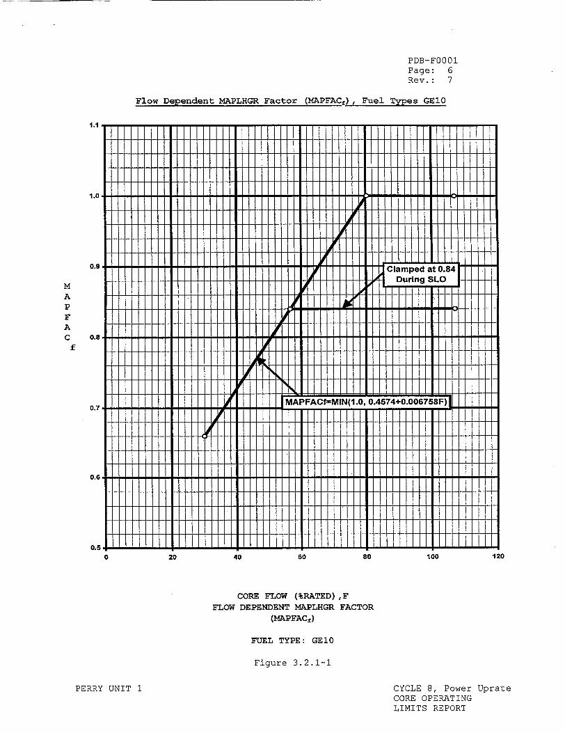
Flow Derfendent MAPLHGR Factor (MAPFAC) , Fuel Tvres GEl0
0 20 40 60 80 100
CORE FLOW (%RATED) ,F
FLOW DEPENDENT MAPLHGR FACTOR
(MAPFACA)
FUEL TYPE: GEl0
Figure 3.2.1-1
PERRY UNIT 1 CYCLE 8, Power Uprate CORE OPERATING LIMITS REPORT
M A P F A C
f
0.6 F
0.5I120
. J1.1
I 1
1.0
0.9 Clamped at 0.84
0 uin SLO
0.8 P
0.7APFACfMIN(1.0, 0.4574+0.006758F
v._
0.5
PDB-FOO01 Page: 7 Rev.: 7
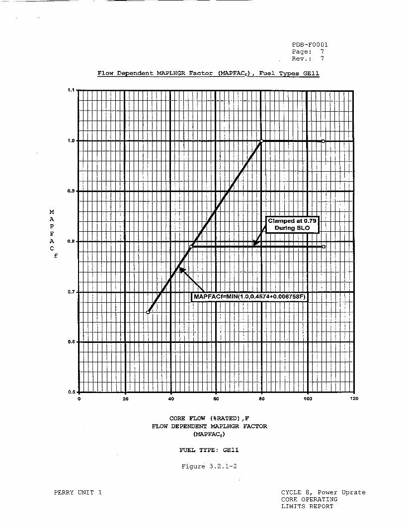
Flow Dependent MAPLHGR Factor (MAPFACf), Fuel Types GEl1
1.1
1.0
0.9
I Du..ng-SLo
IA p.l .ii ..i.l.i.i. I I IW!'-- I I I I I I IF I - I I
I I I I I I I I '.� I I I I I I I I I I I I I I
0.7
0.6
0.5
I��� I ii I
0 20 40 60 80 100
CORE FLOW (%RATED) ,F FLOW DEPENDENT MAPLHGR FACTOR
(MAPFACf)
FUEL TYPE: GEl1
Figure 3.2.1-2
PERRY UNIT 1 CYCLE 8, Power Uprate CORE OPERATING LIMITS REPORT
M A P F A C
f
120
orl I I H , 111
JIL Clamned at
0 .5 ý I I I . . I I I . I I I
MAPFACf--MIN(1.0,0.4574+0.006758F)
11

PDB-FOO01 Page: 8 Rev.: 7
Flow Dependent MAPLHGR Factor (MAPFACf), Fuel Types GE12
1.1
1.0
0.9
Clamped at 0.7 During SLO
0.8I
0.7 '
0.8 Ii
oj11F. 1 I
0.6t20 40 60 80 1000
CORE FLOW (%RATED),F FLOW DEPENDENT MAPLHGR FACTOR
(MAPFACf)
FUEL TYPE: GE12
Figure 3.2.1-2a
PERRY UNIT 1 CYCLE 8, Power Uprate CORE OPERATING LIMITS REPORT
M A P F A C
f
120
Power Dependent MAPLHGR Factor
20 40
(MAPFACJ), Fuel
60
PDB-FOO01 Page: 9 Rev.: 7
Types GEl0
80
CORE THERMAL POWER (%RATED),P POWER DEPENDENT MAPLHGR FACTOR
(MAPFAC.)
FUEL TYPE: GEl0
Figure 3.2.1-3
PERRY UNIT 1 CYCLE 8, Power Uprate CORE OPERATING LIMITS REPORT
M A P F A C
P
0
4 1
0.9.! ! !
II!~ ~ I l~ Cae at i0i84
I! I I I10
MAPFAFAp=1.0+0.0052(P-1001
~23.8%<=P<=38%; Core Flow <=60%
0.5Em8
100
PDB-FOO01 Page: 10 Rev.: 7
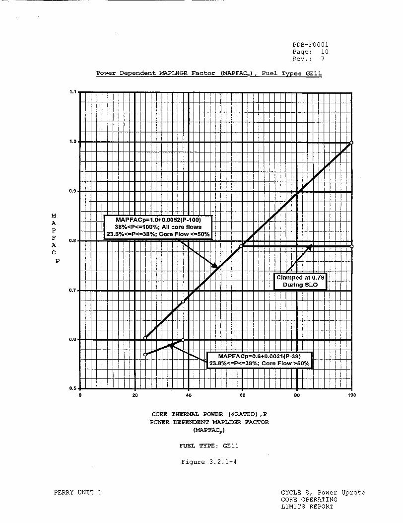
Power Dependent MAPLHGR Factor (MAPFACp), Fuel Types GEl1
1.1
0.9
0.8
0.7
0.6
II II!00
H11~ ll Jl il"00"
MAPFACp=1.0+0.0052(P-100) 1 10 38%<P<=100%; All core flowsI
23.8%<=P<=38%; Core Flow <=50% I ý0111 1 1
Clm e at 0 I 7I
During SLO
C. . MAPFACp=0.6÷0.0021 (P-38) '23.8%<=P<=38%; Core Flow >50%
I~ I I I I40 60
CORE THERMAL POWER (%RATED),P POWER DEPENDENT MAPLHGR FACTOR
(MAPFAC,)
FUEL TYPE: GEl1
Figure 3.2.1-4
PERRY UNIT 1 CYCLE 8, Power Uprate CORE OPERATING LIMITS REPORT
M A P F A C
p
0 20 80 100
|bU
PDB-FOO01 Page: 11 Rev.: 7
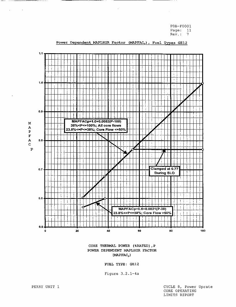
Power Dependent MAPLHGR Factor (MAPFAC.), Fuel Types GE12
1.1 I X I
*2.00 0.I9 00
0.80
0.7
0.50
0.7FA-p=1.0+ped00t(P.70 23.8%<=P<=38%;;CCoreFFlaw<=50%
0.8 Ji ~ii
During SLO
0.6 - 1 1
MAPFACp=0.6+0.0021 (P-38) 23.8%<=P<=38%; Core Flow >50%
0.5- H 1.h
40 60
CORE THERMAL POWER (%RATED),P POWER DEPENDENT MAPLHGR FACTOR
(MAPFAC,)
FUEL TYPE: GE12
Figure 3.2.1-4a
PERRY UNIT 1 CYCLE 8, Power Uprate CORE OPERATING LIMITS REPORT
M A P F A C
P
0 20 80 100
ho
Z
H
I-.
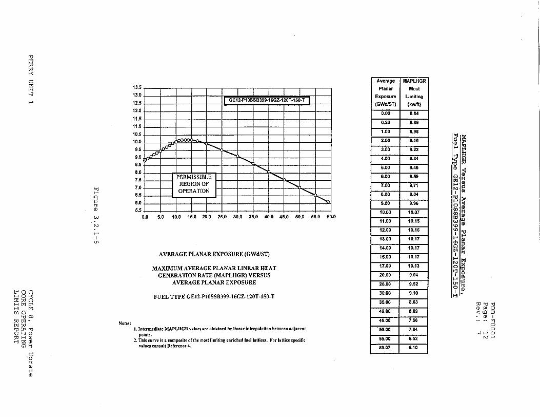
0.0 5.0 10.0 15.0 20.0 25.0 30.0 35.0 40.0 45.0 50.0 55.0 60.0
AVERAGE PLANAR EXPOSURE (GWd/ST)
MAXIMUM AVERAGE PLANAR LINEAR HEAT GENERATION RATE (MAPLHGR) VERSUS
AVERAGE PLANAR EXPOSURE
FUEL TYPE GE12-PIOSSB399-16GZ-120T-150-T
1. Intermediate MAPLHGR values are obtained by linear interpolation between adjacent points.
2. This curve is a composite of the most limiting enriched fuel lattices. For lattice specific values consult Reference 4.
13.5
13.0
12.5 12.0
11.5 11.0
10.5
10.0
9.5
9.0 8.5
8.0 7.5.
7.0.
6.5
6.0
5.5
PERMISSIBLE REGION OF OPERATIONft.
P
(D
(.'
Average
Planar
Exposure
(GWdIST)
0.00
0.20
1.00
2.00
3.00
4.00
5.00
6.00
7.00 8.00
9.00
10.00
11.00
12.00
13.00
14.00
15.00
17.00
20.00
25.00
30.00
35.00
40.00
45.00
50.00
55.00
59.07
MAPLHGR
Most
Limiting
(kwlft)
8.84
8.89
8.98
9.10
9.22
9.34
9.46
9.59
9.71
9.84
9.96
10.07
10.15
10.16
10.17
10.17
10.17
10.13
9.94
9.52
9.10
8.63
8.09
7.56
7.04
6.52
6.10
0-rn< I-IOM I-I
0a0 ,-0 00
a~b OH
1-0
(D
Notes:
.,L •,Il
. -l 1-1 CD.
It L�1
it
C z H H
I-.
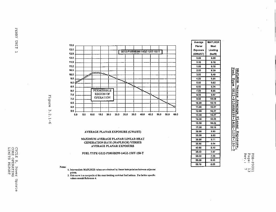
0.0 5.0 10.0 15.0 20.0 25.0 30.0 35.0 40.0 45.0 50.0 55.0 60.0
AVERAGE PLANAR EXPOSURE (GWd/ST)
MAXIMUM AVERAGE PLANAR LINEAR HEAT GENERATION RATE (MAPLHGR) VERSUS
AVERAGE PLANAR EXPOSURE
FUEL TYPE GEI2-PlOSSB399-14GZ-120T-150-T
1. Intermediate MAPLHGR values are obtained by linear interpolation between adjacent points.
2. This curve is a composite of the most limiting enriched fuel lattices. For lattice specific values consult Reference 4.
13 .5 . I I I 130 1_ 1
12.5-,- - -" - j~GE12-Pt0SSB399-14GZ-120T-150-T
_ --.-. _ 112.0 -
10.5 I
10.0 ___ __
9.5
9.0 5P
8.0 PERMISSIBLE 7.5 REGION OF ___
7.0 OPERATION
6.05
5.5 ..
H
t\) L r-
Notes:It 0
(D
(-3 r(
(D
Average
Planar
Exposure (GWd/ST)
0.00
0.20
1.00
2.00
3.00
4.00
5.00
6.00
7.00
8.00
9.00
10.00
11.00
12.00
13.00
14.00
15.00
17.00
20.00
25.00
30.00
35.00
40.00
45.00
60.00
55.00
59.18
MAPLHGR
Most
Limiting
(kw/ft)
9.05
9.10 9.18
9.29
9.40
9.51
9.62
9.74
9.86
9.97
10.09
10.19
10.27
10.27
"10.27 10.26
10.24
10.16
9.95
9.53
9.11
8.64
8.10
7.57
7.05
6.53 6.09
(DW (D I
C)H
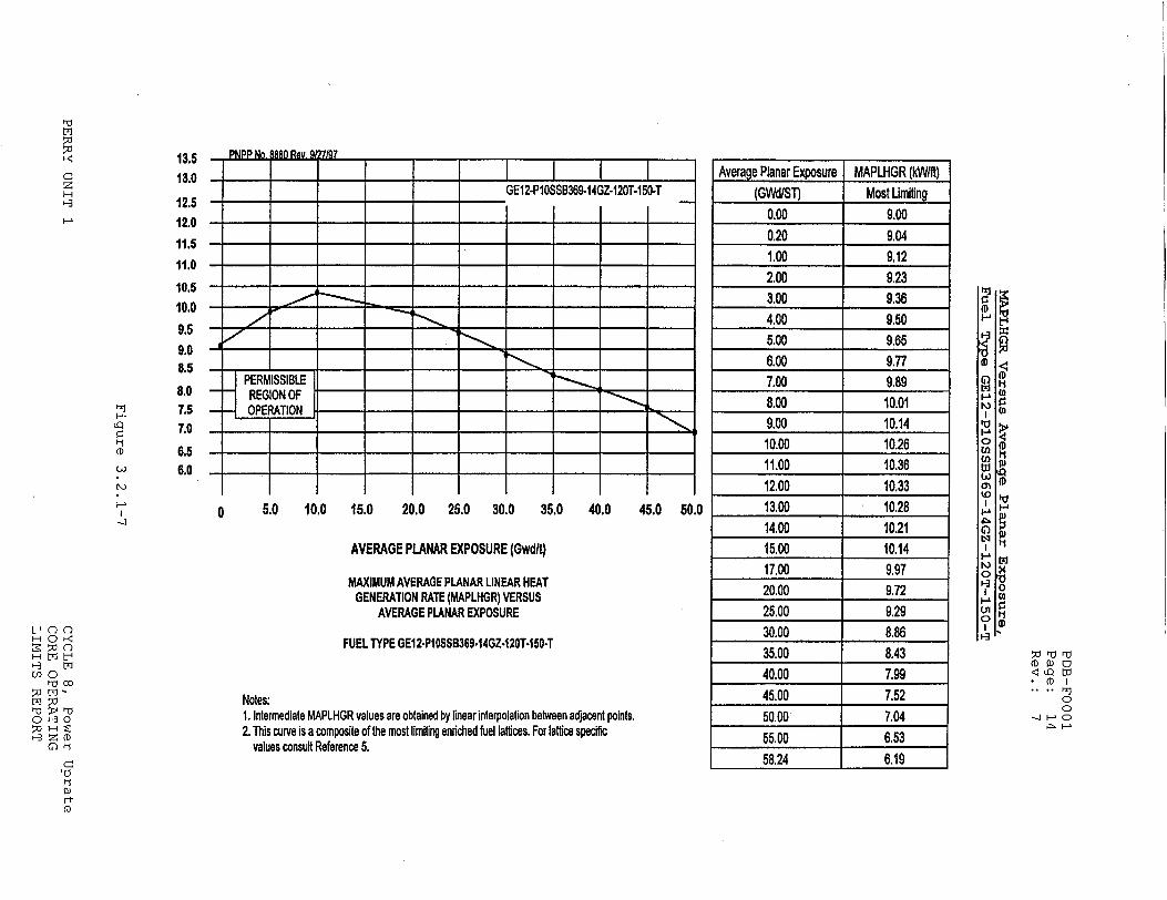
I I I 0 5.0 10.0 15.0
I I I I 1 4 20.0 25.0 30.0 35.0 40.0 45.0 50.0
AVERAGE PLANAR EXPOSURE (Gwdlt)
MAXIMUM AVERAGE PLANAR UNEAR HEAT GENERATION RATE (MAPLHGR) VERSUS
AVERAGE PLANAR EXPOSURE
FUEL TYPE GEI2.P10SSB369.14GZ-120T-150-T
Notes: 1. Intermediate MAPLHGR values are obtained by linear interpolation between adjacent points. 2. This curve is a composite of the most limiting enriched fuel lattices. For lattice specific
values consult Reference 5.
,.tl
z H
I-.
13.5 13.0
12.5 12.0
11.5
11.0
10.5
10.0
9.6 9.0 8.5
8.0 7.5 7.0
6.5 6.0
I-.
LQ
ti
(1
GE12-P10SSB369-14GZ-120T-150-T
PERMISSIBLE REGION OF OPERATION
Average Planar Exposure MAPLHGR (kW/ft) (GWd/ST) Most Limiting
0.00 9.00 0.20 9.04 1.00 9.12 2.00 9.23 3.00 9.36 4.00 9.50 5.00 9.65 6.00 9.77 7.00 9.89 8.00 10.01 9.00 10.14 10.00 10.26 11.00 10.36 12.00 10.33 13.00 10.28 14.00 1021 15.00 10.14 17.00 9.97 20.00 9.72 25.00 9.29 30.00 8.86 35.00 8.43 40.00 7.99 45.00 7.52 50.00 7.04 55.00 6.53 58.24 6.19
0
0 Z~ (D
rtJ Z(D
0
(D
II
LtQ W • (D) I
C) 0 HC
C)

1 1 5.0 10.0 15.0
I I I I I 1 1 20.0 25.0 30.0 35.0 40.0 45.0 50.0
AVERAGE PLANAR EXPOSURE (Gwdlt)
MAXIMUM AVERAGE PLANAR LINEAR HEAT GENERATION RATE (MAPLHGR) VERSUS
AVERAGE PLANAR EXPOSURE
FUEL TYPE GEl2-PI0SS0369ot2GZ-120T.150.T
Notes: 1. Intermediate MAPLHGR values are obtained by linear interpolation between adjacent points. 2. This curve is a composite of the most limiting enriched fuel lattices. For lattice specific
values consult Reference 5.
(rj 13,5 13.0
12.5
12.0
11.5 11.0 10,5
10.0
9.5 9.0 8,5
8.0 7.5
7.0
6.5
6.0
- PP~o. IN2aN. 8 7/97 I
GE12-P10SSB369-12GZ.120T-150-T
PERMISSIBLE -- REGION OF • -OPERATIOýNH,.
(D)
I
co 0
OHO• '0
Co -0
Ct (D
Average Planar Exposure MAPLHGR (kW/ft) (GWd/ST) Most Limiting
0.00 8.89
0.20 8.94
1.00 9.05
2.00 9.19
3.00 9.32
4.00 9.46
5,00 9.61
6.00 9.75
7.00 9.90
8.00 10.05
9.00 10.19
10.00 10.33
11.00 10.41 12.00 10.38
13.00 10.32
14.00 10.25
15.00 10.17
17.00 10.00
20.00 9.74
25.00 9.31
30.00 8.88
35.00 8.45 40.00 8,00 45.00 7.54
50.00 7.05
55.00 6.54
58.22 6.20
-Ci Q W
CDI
0
(D<
(D
(D
to Ii
(D
Ii
C z IH H
H
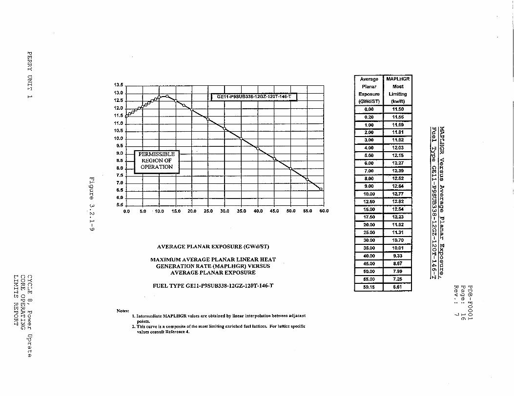
0.0 5.0 10.0 15.0 20.0 25.0 30.0 35.0 40.0 45.0 50.0 55.0 60.0
AVERAGE PLANAR EXPOSURE (GWd/ST)
MAXIMUM AVERAGE PLANAR LINEAR HEAT GENERATION RATE (MAPLHGR) VERSUS
AVERAGE PLANAR EXPOSURE
FUEL TYPE GEll-P9SUB338-12GZ-120T-146-T
Notes:1. Intermediate MIAPLHGR values are obtained by linear interpolation between adjacent
points. 2. This curve is a composite ofathe most limiting enriched fuel lattices. For lattice specific
values consult Reference 4.
13.5
13.0
12.5
12.0
11.5
11.0
10.5
10.0
9.5
9.0
8.5. 8.0.
7.5
7.0
6.5
6.0
5.5
- = I I I I I .. _ _ - GE1PSUB338-12G-120TA146-TJ
PERMISSIBLE - _
REGION OF-OPERATION L
(D N.)
HO
Average
Planar
Exposure (GWd/ST)
0.00
0.20
1.00
2.00
3.00
4.00
5.00
6.00
7.00
8.00
9.00
10.00
12.50
15.00
17.50
20.00
25.00
30.00
35.00
40.00
45.00
50.00 55.00
59.15
MAPLHGR
Most
ULmiting
(kw/ft)
11.50
11.55
11.69
11.81
11.92
12.03
12.15
12.27
12.39
12.52
12.64
12.77
12.82
12.54
12.23
11.92
11.31
10.70
10.01
9.33
8.67
7.99 7.25
H 0 ý< w n0 ti MO
U)1 0t
HaZ (D
C10 ti1 w) (t (D
(D
(D
I1
(DI
0)ý o -
1•0
z H
PERMISSIBLE REGION OF
-4OPERATION
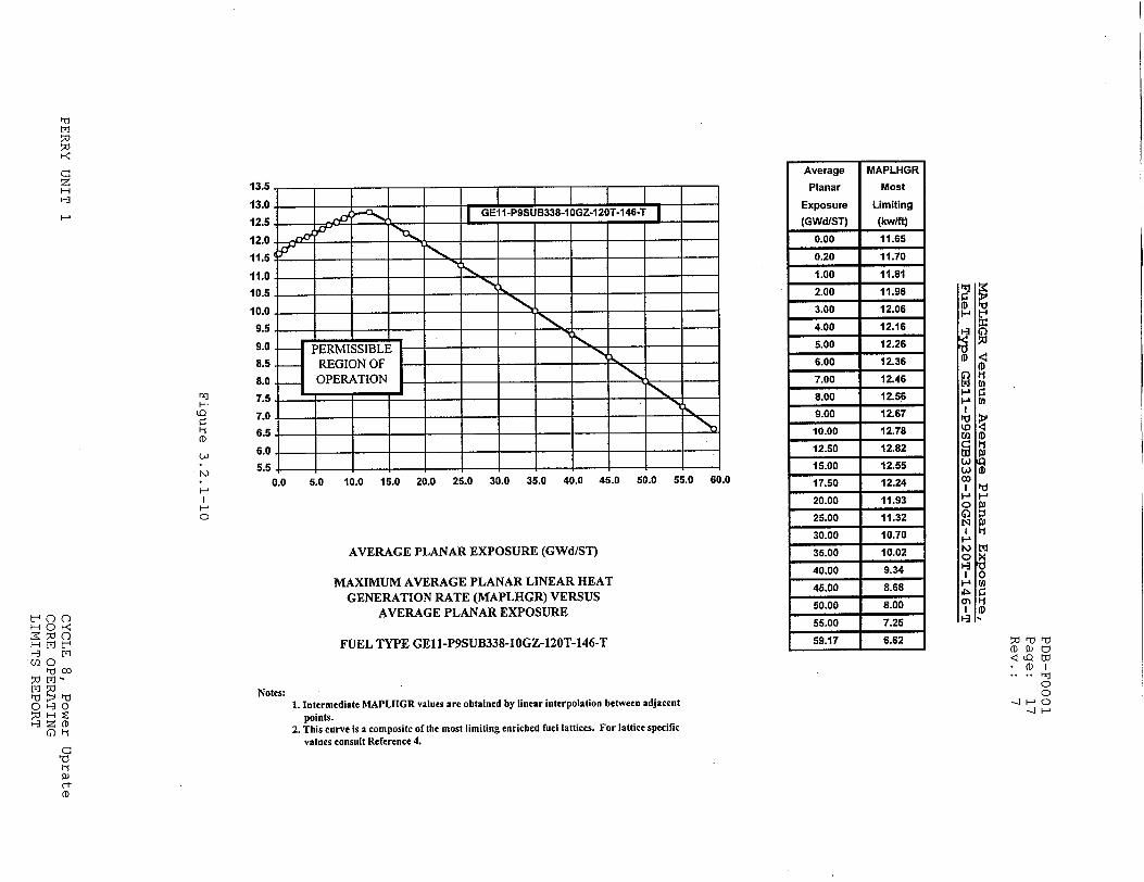
0.0 5.0 10.0
EEKI-EIIFJTV
15.0 20.0 25.0 30.0 35.0 40.0 45.0 50.0 55.0 60.0
AVERAGE PLANAR EXPOSURE (GWd/ST)
MAXIMUM AVERAGE PLANAR LINEAR HEAT
GENERATION RATE (MAPLHGR) VERSUS
AVERAGE PLANAR EXPOSURE
FUEL TYPE GE11-P9SUB338-IOGZ-120T-146-T
1. Intermediate MAPLHGR values are obtained by linear interpolation between adjacent points.
2. This curve is a composite of the most limiting enriched fuel lattices. For lattice specific values consult Reference 4.
13.5 13o.0I I 12.5 - GE11-P9SUB338-10GZ-120T-146-T
12.0 .- : 11.5 •I
11.0 - , - _ ,
10.5 , _
10.0
9.5 - -, ] - _ _
9.0 8.5
8.0
7.5
7.0
6.5
6.0
5.5
Average
Planar
Exposure
(GWd/ST)
0.00
0.20
1.00
2.00
3.00
4.00
5.00
6.00
7.00
8.00
9.00
10.00
12.50
15.00
17.50
20.00
25.00
30.00
35.00
40.00
45.00
50.00
55.00
59.17
r-x
I-i"
(D
I-0 I
H f-<
OHO C0
'00
0 30
Notes:
MAPLHGR
Most
Limiting
(kwlft) 11.65
11.70
11.81
11.96
12.06
12.16
12.26
12.36
12.46
12.56
12.67
12.78
12.82
12.55
12.24
11.93
11.32
10.70
10.02
9.34
8.68
8.00
7.25
6.62(DQ W
C0I 0. .o oJF
.•] i-•
W
to
(D
F1
0
Di (D Ii
!J
5.0 10.0 15.0 20.0 25.0 30.0 35.0 40.0 45.0 50.0 55.0 60.0
AVERAGE PLANAR EXPOSURE (GWd/ST)
MAXIMUM AVERAGE PLANAR LINEAR HEAT GENERATION RATE (MAPLHGR) VERSUS
AVERAGE PLANAR EXPOSURE
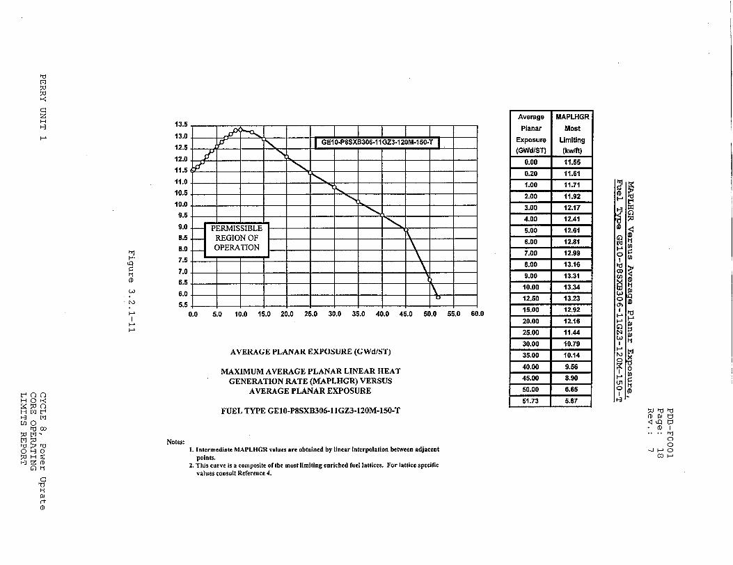
FUEL TYPE GE10-P8SXB306-I IGZ3-120M-I50-T
1. Intermediate MAPLHGR values are obtained by linear interpolation between adjacent points.
2. This curve is a composite of [he most limiting enriched fuel lattices. For lattice specific values consult Reference 4.
CA
0.0
____ ____ - G-10-P8SXB306-11GZ3-120M-150-T.
PERMISSIBLE REGION OF OPERATION
13.5
13.0
12.5
12.0
11.6
11.0
10.5
10.0
9.5
9.0.
8.5.
8.0.
7.5
7.0
6.5
6.0
5.5
LQ
(.D I
H--
•0 ý
C/)0
r-t
H(D
Average
Planar
Exposure
(GWd/ST)
0.00
0.20
1.00
2.00
3.00
4.00
5.00
6.00
7.00
8.00
9.00
10.00
12.50
15.00
20.00 25.00
30.00
35.00
40.00
45.00
50.00
51.73
MAPLHGR
Most
Limiting
(kw/ft)
11.55
11.61
11.71
11.92
12.17 12.41
12.61
12.81
12.99
13.16
13.31
13.34
13.23
12.92
12.16
11.44
10.79
10.14
9.56
8.90
6.65
5.87
Notes:Co .,... w.•( o*( )i--

PDB-FOO01 Page: 19 Rev.: 7
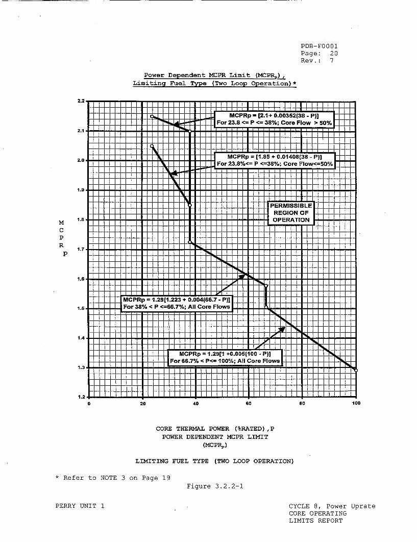
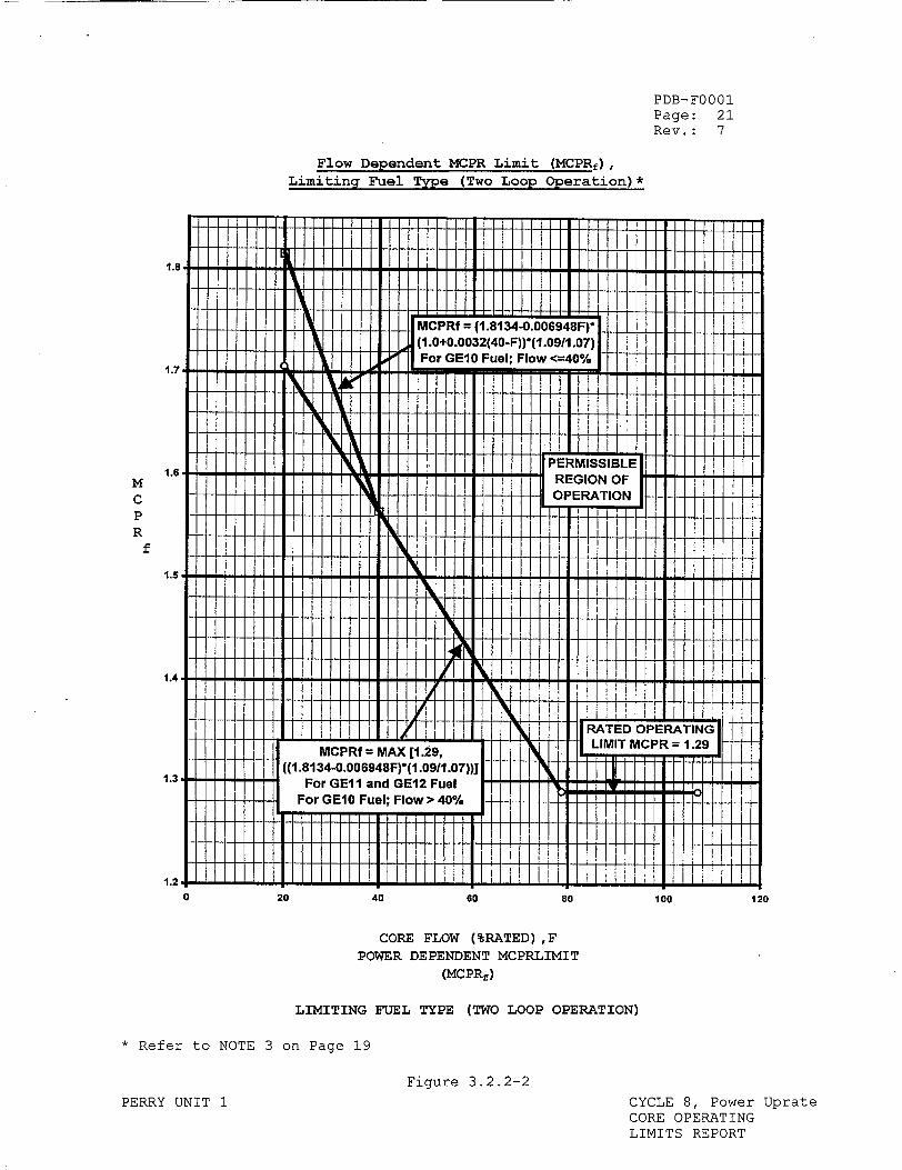
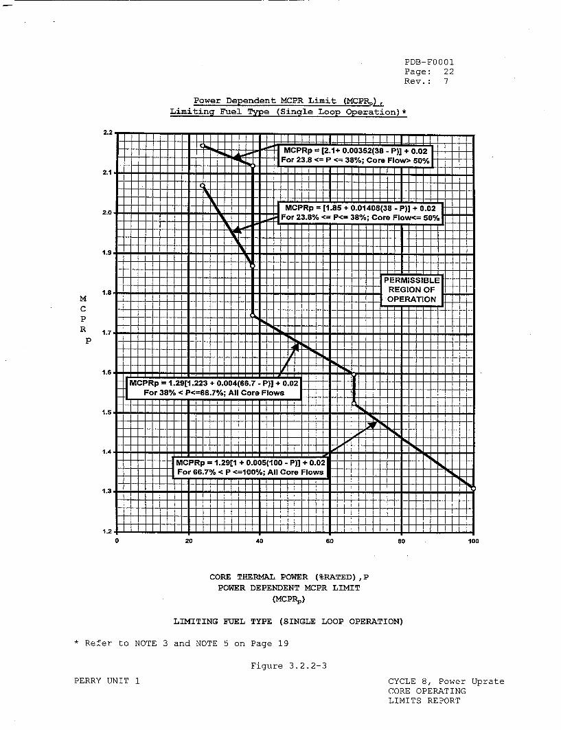
MINIMUM CRITICAL POWER RATIO (TS 3.2.2)
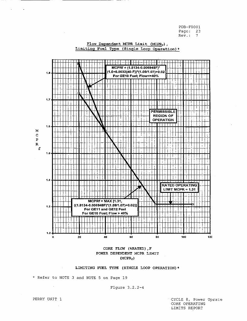
The MINIMUM CRITICAL POWER RATIO (MCPR) shall be equal to or greater than the higher of the MCPRf and MCPRp limits at the indicated core flow, THERMAL POWER, and delta T* as specified in Figures 3.2.2-1 and 3.2.2-2 for Two Loop Operation and Figures 3.2.2-3 and 3.2.2-4 for Single Loop Operation.
The MCPR Safety Limit for Cycle 8, Power Uprate, is 1.09. The MCPR Safety Limit for Single Loop Operation is 1.11 <TECHNICAL SPECIFICATIONS 2.1.1.2>. During Single Loop Operation, the Maximum Fraction of Limiting Critical Power Ratio (MFLCPR) shall be equal to or less than 0.98. Use FTI-B12 Single Loop Operation implements this revised MFLCPR.
NOTE 1: For Cycle 8, Power Uprate, no change to MCPR limits is required for planned reduction of feedwater temperature to as low as 325.5'F. Final feedwater temperature may be reduced to 255.5 0 F after all control rods are withdrawn at the end of cycle.
NOTE 2: Planned reduction of rated feedwater temperature from nominal rated feedwater temperature is not permitted during plant operation with the reactor recirculation system in Single Loop Operation.
NOTE 3: Figures 3.2.2-1 and 3.2.2-2, depict the limiting fuel type for Two Loop Operation. Figures 3.2.2-3 and 3.2.2-4 depict the limiting fuel type for Single Loop operation. For fuel type specific values, consult Reference 3.
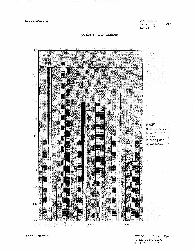
Attachment 1 illustrates the limiting transient for each fuel type. The thermal limits calculation uses whichever is highest (MCPRf or MCPRp) for the given power and flow condition.
NOTE 4: There are a total of 19 safety/relief valves, the two lowest setpoint valves are assumed to be out-of-service in the transient analysis.
NOTE 5: The MCPR operating limit is increased 0.02 to account for the increase in the single loop MCPR safety limit with the reactor recirculation system in single loop operation.
* This delta T refers to the planned reduction of rated feedwater temperature
from nominal rated feedwater temperature (425.5'F), such as prolonged removal of feedwater heater(s) from service.
PERRY UNIT 1 CYCLE 8, Power Uprate CORE OPERATING LIMITS REPORT
PDB-FOO01 Page: 20 Rev.: 7
Power Dependent MCPR Limit (MCPR)),Limiting Fuel Type (Two Loop Operation)*
I I I I I II I I I II I I I I I I I I III I I 11171l III I I I I1111111 111111111 I 11111 II�
mMCPRp = [2.1+ 0.00352(38 - P)] 0 For 23.8 <= P <= 38%: Core Flow > 50%
-.... I
2.8 MCRp = [1.85 + 0.01408(38 - P)]
For 23.8%<= P <=38%; Core Flow<=50%F
.2 5 PERMISSIBLE REGION OF
1.8 OPERATION
1.7
1.4
MCP~p 1.9[ +0.005.100 + P)0(6• ) l.SFor 66.% < P < <--60,%; All Core Flows
.4I I!! I I ! -L I 1I, 111
M P p=1 211 +.0(0 )
I. ; I I 1 ## 1 1 11 1
20 40 60 80 100
CORE THERMAL POWER (%RATED) ,P
POWER DEPENDENT MCPR LIMIT (MCPRp)
LIMITING FUEL TYPE (TWO LOOP OPERATION)
* Refer to NOTE 3 on Page 19Figure 3.2.2-1
PERRY UNIT 1 CYCLE 8, Power Uprate CORE OPERATING LIMITS REPORT
2.1 1 1 1 1 i i 1 .............
M C P R
p
0
Z- I I I
Ji i i i ii ii i
iii
PDB-FOO01 Page: 21 Rev.: 7
Flow Dependent MCPR Limit (MCPRf), Limiting Fuel Type (Two Loop Operation)*
1.8"
MCPRf =(1.8134-0.006948F)* (1.0+0.0032(40-F))'(1.0911.07)
WFor GE10 Fuel; Flow <--40%°V 1.7, ,
i IVi I i N, IN IW
]1 PERMISSIBLE
li REGION OF ' :OPERATION
I I
IHI
1.4 V
H 1
• _ RATED OPERATING:
I tI MP~f MA [129,LIMIT MCPIR 1.29
1.3 i iJ (11.8134-0.006948F)*(1.09/11.07))] 1.3 For GE11 and GE12 Fuel
For GE10 Fuel; Flow > 40%
[11 illt liil llll1 14]
80
I! I 1111111 1 111 l ill
20 40 60 100
CORE FLOW (%RATED) ,F
POWER DEPENDENT MCPRLIMIT
(MCPRf)
LIMITING FUEL TYPE (TWO LOOP OPERATION)
* Refer to NOTE 3 on Page 19
Fiqure 3.2.2-2
PERRY UNIT 1 CYCLE 8, Power Uprate CORE OPERATING LIMITS REPORT
M C P R
f
0 120
ii:llilii:
PDB-FOO01 Page: 22 Rev.: 7
Power Dependent MCPR Limit (MCPRP),Limiting Fuel Type (Single Loop Operation)*
2.2 ....... 1 1 - III
S. . ..MCPRp = [2.1+ 0.00352(38 - P)] + 0.0 21
: : ' '' 'For 23.8 <= P <= 38%; Core Flow 50%
2.1 1 1 1 1 I- - -F T - I 1 1 1 1 1 ! 1
2. ... .. MCPRp =[1.85 + 0.01408(38 - P)] + 0.02 2.0 :: : : :: Fo 23.% <=P<= 38%; Core Flow<=50
1 .. .. PERMISSIBLE
1.8 : :: i :REGION OF
S... ... OPERATION
1.7 : : : : : :
Fo 38 < P<6.% Al Cor FI
1.4
MCP~p =1.2911.23 + 0.048.7 - )] +0.02P 0 For 66.% < P<=6 100%; All Core Flows
1.3 , 1 11 1
1.2,I~
20 40 60 80
CORE THERMAL POWER (%RATED),P POWER DEPENDENT MCPR LIMIT
(MCPRP)
LIMITING FUEL TYPE (SINGLE LOOP OPERATION)
* Refer to NOTE 3 and NOTE 5 on Page 19
Figure 3.2.2-3
PERRY UNIT 1 CYCLE 8, Power Uprate CORE OPERATING LIMITS REPORT
M C P R
P
0 100
PDB-FOO01 Page: 23 Rev.: 7
Flow Dependent MCPR Limit (MCPRE), Limiting Fuel Type (Single Loop Operation)*
MCPRf = (1.8134-0.006948F)* (1 .0+0.0032(40-F))*(1.0911.07)+0.0214
For GE10 Fuel; Flow<=40% I!
PEMISIL
H I I II v7 I!III ! 111 liii; I ii I I:r1 III
IMCPRf = MAX [1.31,
((1.8134-0.006948F)*(1.0911.07)+0.02)] For GE1I and GEl2 Fuel 11
For GEl0 Fuel; Flow > 40%
1111111 II 111111 I I I
RTED OPERATING LIMT MCPR 1.31~
-F-+fI III IIIII----I-----I-+-
II IFII I
1ii
II; !6 1. 6 * 6 �
II!
II !
LliI
S.C - -h -, S - S -20 40 60 80
CORE FLOW (%RATED) ,F
POWER DEPENDENT MCPR LIMIT (MCPRf)
LIMITING FUEL TYPE (SINGLE LOOP OPERATION)*
* Refer to NOTE 3 and NOTE 5 on Page 19
Figure 3.2.2-4
PERRY UNIT 1
100 12C
1.8
M C P R
f1.6
1.4
1.3 .
0
CYCLE 8, Power Uprate CORE OPERATING LIMITS REPORT
Sf
1 1 H 11 1 1 1 1 1 11 11 1 I NJ
11 X PERMISSIBLE
REGION OF 0 EIRATION i
Ii 11H IH I I I H IM H
Li I I
= - - ILL -LLI ILL I
illij ! I I I I 1-M,
1.7
1.6
•011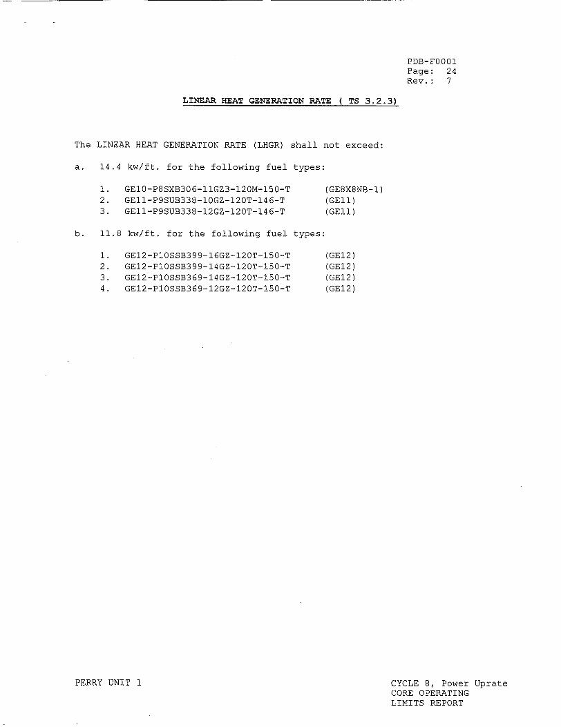
PDB-FOO01 Page: 24 Rev.: 7
LINEAR HEAT GENERATION RATE ( TS 3.2.3)
The LINEAR HEAT GENERATION RATE (LHGR) shall not exceed:
a. 14.4 kw/ft. for the following fuel types:
GE10-P8SXB306-11GZ3-120M-150-T GEI1-P9SUB338-10GZ-120T-146-T GE11-P9SUB338-12GZ-120T-146-T
(GE8X8NB-1) (GEl1) (GE11)
b. 11.8 kw/ft. for the following fuel types:
1. GE12-PlOSSB399-16GZ-120T-150-TGE12-PlOSSB399-14GZ-120T-150-T GE12-P1OSSB369-14GZ-120T-150-T GE12-PIOSSB369-12GZ-120T-150-T
PERRY UNIT 1
(GEl2) (GEl2) (GE12)
(GE12)
CYCLE 8, Power Uprate CORE OPERATING LIMITS REPORT
1.
2. 3.
2. 3. 4.
PDB-FOO01 Page: 25 Rev.: 7
REACTOR PROTECTION SYSTEM INSTRUNENTATION ( TS 3.3.1.1)
The simulated thermal power time constant shall be 6+/-0.6 seconds.
CYCLE 8, Power Uprate CORE OPERATING LIMITS REPORT
PERRY UNIT 1
Attachment 1 PDB-FOO01 Page: 26 - LAST Rev.: 7
Cycle 8 MCPR Limits
1.3
1.28
1.26
1.24
1.22
1.2
1.18
1.16
1.14
1.12
1.1
GE12 GElI
OMRWE
! FLE, misorientated
i FLE, mislocated i 0 LFWH
GEi0
PERRY UNIT 1 CYCLE 8, Power Uprate CORE OPERATING LIMITS REPORT