perkins gas eng. 8.0-sm
DESCRIPTION
Service ManualTRANSCRIPT
8.0L GaseousEngine Service Manual
NOTE: Some illustrations in this manual may differ from the actual product. Use the Exploded Views in Section 1 for reference.
NOTE: Ensure that proper safety protocols are practiced when servicing this product.
ii 8.0L Gaseous Engine Service Manual
WARNING!California Proposition 65
Engine exhaust and some of its constituents are known to the state of California to cause cancer, birth defects, and other reproductive harm.
WARNING!California Proposition 65
This product contains or emits chemicals known to the state of California to cause cancer,birth defects, and other reproductive harm.
Table of ContentsTable of Contents
NOTE: Some descriptions and illustrations may differ from the actual product.
Section 1 Specifications & Exploded Views
1.1 8.0L Engine ............................................................................................................................................11.1.1 Torque Specifications ...................................................................................................................................11.1.2 Engine Tolerances and Wear Limits ............................................................................................................3
1.2 Exploded Views ....................................................................................................................................61.2.1 Flywheel ..........................................................................................................................................................61.2.2 Water Pump ....................................................................................................................................................71.2.3 Reluctor ..........................................................................................................................................................81.2.4 Intake Manifold ...............................................................................................................................................91.2.5 Piston ............................................................................................................................................................101.2.6 Crankshaft ....................................................................................................................................................111.2.7 Valve Cover ..................................................................................................................................................121.2.8 Distributor ....................................................................................................................................................131.2.9 Engine Block (1 of 3) ...................................................................................................................................141.2.10 Engine Block (2 of 3) .................................................................................................................................151.2.11 Engine Block (3 of 3) .................................................................................................................................161.2.12 Other Assemblies ......................................................................................................................................17
Section 2 Diagnostics
2.1 Base Engine Misfire Diagnosis .........................................................................................................19
2.2 Engine Noise Diagnosis .....................................................................................................................21
2.3 General Information ............................................................................................................................242.3.1 Diagnostic Table ..........................................................................................................................................25
2.4 Oil Leak Diagnosis ..............................................................................................................................27
2.5 Drive Belt .............................................................................................................................................302.5.1 Visual/Physical Inspection ..........................................................................................................................302.5.2 Intermittent ...................................................................................................................................................302.5.3 Diagnostic Aids ............................................................................................................................................302.5.4 Symptom List ...............................................................................................................................................30
2.6 Drive Belt Chirping .............................................................................................................................302.6.1 Test Description ...........................................................................................................................................30
2.7 Drive Belt Squeal ................................................................................................................................322.7.1 Diagnostic Aids ............................................................................................................................................322.7.2 Test Description ...........................................................................................................................................32
2.8 Drive Belt Whine .................................................................................................................................342.8.1 Diagnostic Aids ............................................................................................................................................342.8.2 Test Description ...........................................................................................................................................34
2.9 Drive Belt Rumbling ...........................................................................................................................342.9.1 Diagnostic Aids ............................................................................................................................................342.9.2 Test Description ...........................................................................................................................................35
2.10 Drive Belt Vibration ..........................................................................................................................362.10.1 Diagnostic Aids ..........................................................................................................................................362.10.2 Test Description .........................................................................................................................................36
8.0L Gaseous Engine Service Manual iii

Table of Contents
2.11 Drive Belt Falls Off ............................................................................................................................ 372.11.1 Diagnostic Aids ......................................................................................................................................... 372.11.2 Test Description ........................................................................................................................................ 37
2.12 Drive Belt Excessive Wear ............................................................................................................... 392.12.1 Diagnostic Aids ......................................................................................................................................... 392.12.2 Test Description ........................................................................................................................................ 392.12.3 Inspection Procedure ................................................................................................................................ 39
Section 3 Subassembly Service
3.1 Preliminary Instructions ..................................................................................................................... 41
3.2 Drive Belt ............................................................................................................................................. 413.2.1 Removal ....................................................................................................................................................... 413.2.2 Installation ................................................................................................................................................... 41
3.3 Drive Belt Tensioner ........................................................................................................................... 423.3.1 Removal ....................................................................................................................................................... 423.3.2 Installation ................................................................................................................................................... 43
3.4 Idler Pulley ........................................................................................................................................... 433.4.1 Removal ....................................................................................................................................................... 433.4.2 Installation ................................................................................................................................................... 43
3.5 Accessory Mounting Bracket ............................................................................................................ 443.5.1 Removal ....................................................................................................................................................... 443.5.2 Installation ................................................................................................................................................... 45
3.6 Generator Bracket .............................................................................................................................. 463.6.1 Removal ....................................................................................................................................................... 463.6.2 Installation ................................................................................................................................................... 47
3.7 Distributor ........................................................................................................................................... 483.7.1 Removal ....................................................................................................................................................... 483.7.2 Assembly ..................................................................................................................................................... 483.7.3 Set Distributor Timing ................................................................................................................................. 50
3.8 Intake Manifold .................................................................................................................................... 523.8.1 Removal ....................................................................................................................................................... 523.8.2 Installation ................................................................................................................................................... 523.8.3 Removal ....................................................................................................................................................... 533.8.4 Installation ................................................................................................................................................... 54
3.9 Rocker Arm Cover .............................................................................................................................. 553.9.1 Removal ....................................................................................................................................................... 553.9.2 Installation ................................................................................................................................................... 57
3.10 Push Rod ........................................................................................................................................... 583.10.1 Removal ..................................................................................................................................................... 583.10.2 Installation ................................................................................................................................................. 59
3.11 Valves ................................................................................................................................................ 603.11.1 Removal ..................................................................................................................................................... 603.11.2 Installation ................................................................................................................................................. 61
3.12 Valve Lifters ...................................................................................................................................... 623.12.1 Removal ..................................................................................................................................................... 623.12.2 Installation ................................................................................................................................................. 64
iv 8.0L Gaseous Engine Service Manual
Table of Contents
3.13 Oil Level Indicator Tube ...................................................................................................................643.13.1 Removal ......................................................................................................................................................643.13.2 Installation ..................................................................................................................................................65
3.14 Oil Pressure Sensor .........................................................................................................................653.14.1 Removal ......................................................................................................................................................653.14.2 Installation ..................................................................................................................................................65
3.15 Exhaust Manifolds ............................................................................................................................663.15.1 Removal ......................................................................................................................................................663.15.2 Installation ..................................................................................................................................................66
3.16 Cylinder Heads ..................................................................................................................................673.16.1 Removal ......................................................................................................................................................673.16.2 Installation ..................................................................................................................................................68
3.17 Crankshaft Balancer .........................................................................................................................693.17.1 Removal ......................................................................................................................................................693.17.2 Installation ..................................................................................................................................................70
3.18 Crankshaft Oil Seal ...........................................................................................................................713.18.1 Removal ......................................................................................................................................................713.18.2 Installation ..................................................................................................................................................72
3.19 Crankshaft Front Cover ....................................................................................................................723.19.1 Removal ......................................................................................................................................................723.19.2 Installation ..................................................................................................................................................72
3.20 Reluctor Ring ....................................................................................................................................733.20.1 Removal ......................................................................................................................................................733.20.2 Installation ..................................................................................................................................................73
3.21 Crankshaft Sprocket .........................................................................................................................743.21.1 Removal ......................................................................................................................................................743.21.2 Installation ..................................................................................................................................................75
3.22 Camshaft ...........................................................................................................................................763.22.1 Removal ......................................................................................................................................................763.22.2 Installation ..................................................................................................................................................77
3.23 Oil Filter Bypass Valves ...................................................................................................................793.23.1 Removal ......................................................................................................................................................793.23.2 Installation ..................................................................................................................................................79
3.24 Oil Pan ...............................................................................................................................................803.24.1 Removal ......................................................................................................................................................803.24.2 Installation ..................................................................................................................................................81
3.25 Oil Pump ............................................................................................................................................823.25.1 Removal ......................................................................................................................................................823.25.2 Installation ..................................................................................................................................................82
3.26 Crankshaft Rear Oil Seal ..................................................................................................................823.26.1 Removal ......................................................................................................................................................823.26.2 Installation ..................................................................................................................................................82
3.27 Flywheel .............................................................................................................................................833.27.1 Removal ......................................................................................................................................................833.27.2 Installation ..................................................................................................................................................83
8.0L Gaseous Engine Service Manual v
Table of Contents
3.28 Lift Brackets ...................................................................................................................................... 833.28.1 Removal ..................................................................................................................................................... 833.28.2 Installation ................................................................................................................................................. 84
3.29 Oil Pan Drain Plug ............................................................................................................................ 863.29.1 Removal ..................................................................................................................................................... 863.29.2 Installation ................................................................................................................................................. 87
3.30 Inspect Engine .................................................................................................................................. 87
3.31 Final Instructions .............................................................................................................................. 88
Section 4 Engine Disassembly
4.1 Drain Oil ............................................................................................................................................... 89
4.2 Drain Coolant ...................................................................................................................................... 89
4.3 Flywheel ............................................................................................................................................... 89
4.4 Flywheel Housing ............................................................................................................................... 90
4.5 Oil Level Indicator ............................................................................................................................... 91
4.6 Spark Plug ........................................................................................................................................... 92
4.7 Exhaust Manifold ................................................................................................................................ 93
4.8 Heat Shields ........................................................................................................................................ 93
4.9 Water Pump ......................................................................................................................................... 94
4.10 Front Lift Bracket .............................................................................................................................. 95
4.11 Crankshaft Pulley ............................................................................................................................. 95
4.12 Crankshaft Balancer ......................................................................................................................... 96
4.13 Rocker Arm Cover ............................................................................................................................ 97
4.14 Distributor ......................................................................................................................................... 98
4.15 Intake Manifold .................................................................................................................................. 99
4.16 Rocker Arms/Push Rods ................................................................................................................ 101
4.17 Spark Plugs ..................................................................................................................................... 102
4.18 Cylinder Head .................................................................................................................................. 102
4.19 Valve Lifters .................................................................................................................................... 104
4.20 Oil Pan ............................................................................................................................................. 105
4.21 Oil Pump .......................................................................................................................................... 107
4.22 Engine Front Cover ........................................................................................................................ 107
4.23 Camshaft/Crankshaft Sprockets ................................................................................................... 108
4.24 Camshaft ......................................................................................................................................... 110
4.25 Piston/Connecting Rod .................................................................................................................. 110
4.26 Crankshaft/Crankshaft Bearing ..................................................................................................... 113
4.27 Oil Fitting ......................................................................................................................................... 114
4.28 Engine Block Plugs ........................................................................................................................ 115
vi 8.0L Gaseous Engine Service Manual

Table of Contents
Section 5 Cleaning and Inspection
5.1 Engine Block .....................................................................................................................................121
5.2 Cylinder .............................................................................................................................................1225.2.1 Cylinder Honing .........................................................................................................................................1225.2.2 Cylinder Boring ..........................................................................................................................................123
5.3 Crankshaft .........................................................................................................................................124
5.4 Crankshaft/Connecting Rod Bearings ............................................................................................1275.4.1 Crankshaft and Connecting Rod Bearing Clearances ...........................................................................1285.4.2 Measure Crankshaft Bearings Using Micrometer ...................................................................................1285.4.3 Measure Connecting Rod Bearings Using Micrometer ..........................................................................1295.4.4 Measure Main Bearings Using Plastic Gauge .........................................................................................1305.4.5 Measure Connecting Rod Bearings Using Plastic Gauge .....................................................................1325.4.6 Measure Crankshaft End Play ..................................................................................................................1345.4.7 Measure Connecting Rod Side Clearance ...............................................................................................135
5.5 Flywheel .............................................................................................................................................136
5.6 Piston .................................................................................................................................................137
5.7 Connecting Rod ................................................................................................................................141
5.8 Piston Ring ........................................................................................................................................141
5.9 Piston/Cylinder .................................................................................................................................141
5.10 Piston Pin/Piston Ring ..................................................................................................................143
5.11 Camshaft Bearing ...........................................................................................................................144
5.12 Camshaft .........................................................................................................................................146
5.13 Camshaft Bearings .........................................................................................................................147
5.14 Camshaft/Crankshaft Sprockets ...................................................................................................149
5.15 Valve Components .........................................................................................................................150
5.16 Cylinder Head ..................................................................................................................................1545.16.1 Visual Inspection .....................................................................................................................................1545.16.2 Flatness Measurement ............................................................................................................................1545.16.3 Valves .......................................................................................................................................................1545.16.4 Measurement Valve Springs ...................................................................................................................1555.16.5 Measure Valve Guides .............................................................................................................................1555.16.6 Valve Guide Reaming ..............................................................................................................................1565.16.7 Valve Reconditioning ..............................................................................................................................1575.16.8 Valve Seat Reconditioning ......................................................................................................................1575.16.9 Valve Installation .....................................................................................................................................1585.16.10 Check Valve Spring Installed Height ....................................................................................................158
5.17 Oil Pump Inspection .......................................................................................................................159
5.18 Oil Pan .............................................................................................................................................164
5.19 Engine Front Cover ........................................................................................................................165
5.20 Exhaust Manifold ............................................................................................................................168
5.21 Water Pump .....................................................................................................................................169
5.22 Damaged Thread Repair ................................................................................................................169
8.0L Gaseous Engine Service Manual vii
Table of Contents
Section 6 Engine Assembly
6.1 Oil Filter Bypass Valves ................................................................................................................... 171
6.2 Engine Block Plugs .......................................................................................................................... 1716.2.1 Top Oil Gallery Plugs ................................................................................................................................ 1716.2.2 Rear Oil Gallery Plugs ............................................................................................................................... 1716.2.3 Front Oil Gallery Plugs ............................................................................................................................. 1726.2.4 Left Oil Gallery Plugs ................................................................................................................................ 1726.2.5 Oil Cooler Plugs ........................................................................................................................................ 1726.2.6 Oil Cooler Hose Fittings ........................................................................................................................... 1736.2.7 Coolant Drain Plug .................................................................................................................................... 1736.2.8 Knock Sensors/Knock Sensor Shields ................................................................................................... 1736.2.9 Camshaft Rear Bearing Hole Plug ........................................................................................................... 1746.2.10 Expansion Plugs ..................................................................................................................................... 174
6.3 Oil Bypass Valves ............................................................................................................................. 175
6.4 Oil Filter Fitting ................................................................................................................................. 175
6.5 Crankshaft/Crankshaft Bearings ..................................................................................................... 175
6.6 Pistons/Connecting Rods ................................................................................................................ 179
6.7 Camshaft ........................................................................................................................................... 182
6.8 Crankshaft/Camshaft Sprockets ..................................................................................................... 182
6.9 Engine Front Cover .......................................................................................................................... 184
6.10 Oil Pump .......................................................................................................................................... 185
6.11 Oil Pan ............................................................................................................................................. 186
6.12 Valve Lifters .................................................................................................................................... 188
6.13 Cylinder Head .................................................................................................................................. 188
6.14 Push Rods/Rocker Arms ................................................................................................................ 191
6.15 Splash Shield .................................................................................................................................. 194
6.16 Intake Manifold ................................................................................................................................ 194
6.17 Distributor ....................................................................................................................................... 196
6.18 Rocker Arm Cover .......................................................................................................................... 196
6.19 Crankshaft Balancer ....................................................................................................................... 199
6.20 Crankshaft Pulley ........................................................................................................................... 201
6.21 Front Lift Bracket ............................................................................................................................ 202
6.22 Water Pump ..................................................................................................................................... 202
6.23 Exhaust Manifold/Heat Shield ....................................................................................................... 203
6.24 Flywheel Housing ........................................................................................................................... 206
6.25 Flywheel ........................................................................................................................................... 207
viii 8.0L Gaseous Engine Service Manual
Table of Contents
Section 7 Tools, Methods and Materials
7.1 Parts Description ..............................................................................................................................2097.1.1 Cylinder Block ............................................................................................................................................2097.1.2 Cylinder Head .............................................................................................................................................2097.1.3 Camshaft ....................................................................................................................................................2107.1.4 Crankshaft ..................................................................................................................................................2107.1.5 Pistons and Connecting Rods ..................................................................................................................2107.1.6 Valve Train ..................................................................................................................................................2107.1.7 Intake Manifold ...........................................................................................................................................2107.1.8 Exhaust Manifold .......................................................................................................................................2107.1.9 Drive Belt ....................................................................................................................................................2107.1.10 Torque Values and/or Fastener Tightening Strategies ........................................................................2117.1.11 Engine Mechanical Diagnostic Procedure Revisions ..........................................................................211
7.2 Repair Methods .................................................................................................................................2117.2.1 Gasket Reuse and Applying Sealant ........................................................................................................2127.2.2 Separating Components ...........................................................................................................................2127.2.3 Cleaning Gasket Surfaces .........................................................................................................................2127.2.4 Assembling Components ..........................................................................................................................212
7.3 Tools and Materials ..........................................................................................................................2137.3.1 Sealant Types .............................................................................................................................................2137.3.2 Aerobic Type Room Temperature Vulcanizing (RTV) Sealant ...............................................................2137.3.3 Anaerobic Type Gasket Eliminator Sealant .............................................................................................2147.3.4 Anaerobic Type Threadlock Sealant ........................................................................................................2147.3.5 Anaerobic Type Pipe Sealant ....................................................................................................................2147.3.6 Tools and Equipment ................................................................................................................................215
7.4 Special Tools .....................................................................................................................................216
8.0L Gaseous Engine Service Manual ix

Table of Contents
This page intentionally left blank.
x 8.0L Gaseous Engine Service Manual
Section 1 Specifications & Exploded Views
1.1 — 8.0L Engine
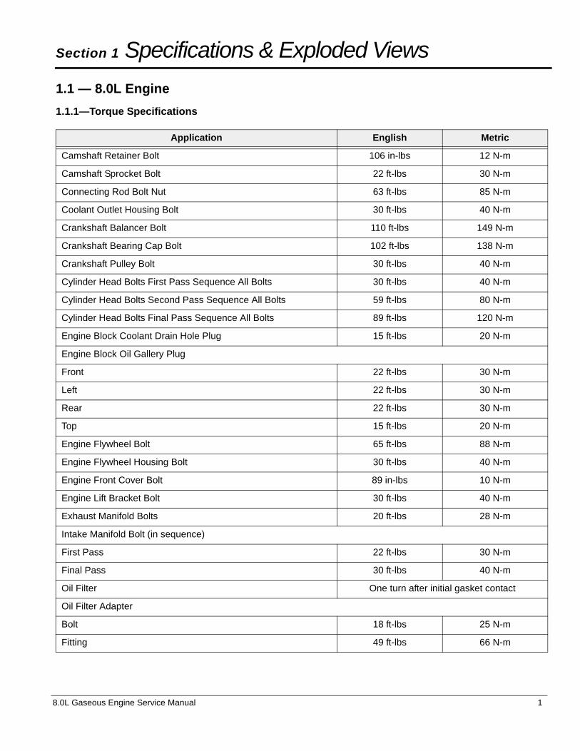
1.1.1—Torque Specifications
Application English Metric
Camshaft Retainer Bolt 106 in-lbs 12 N-m
Camshaft Sprocket Bolt 22 ft-lbs 30 N-m
Connecting Rod Bolt Nut 63 ft-lbs 85 N-m
Coolant Outlet Housing Bolt 30 ft-lbs 40 N-m
Crankshaft Balancer Bolt 110 ft-lbs 149 N-m
Crankshaft Bearing Cap Bolt 102 ft-lbs 138 N-m
Crankshaft Pulley Bolt 30 ft-lbs 40 N-m
Cylinder Head Bolts First Pass Sequence All Bolts 30 ft-lbs 40 N-m
Cylinder Head Bolts Second Pass Sequence All Bolts 59 ft-lbs 80 N-m
Cylinder Head Bolts Final Pass Sequence All Bolts 89 ft-lbs 120 N-m
Engine Block Coolant Drain Hole Plug 15 ft-lbs 20 N-m
Engine Block Oil Gallery Plug
Front 22 ft-lbs 30 N-m
Left 22 ft-lbs 30 N-m
Rear 22 ft-lbs 30 N-m
Top 15 ft-lbs 20 N-m
Engine Flywheel Bolt 65 ft-lbs 88 N-m
Engine Flywheel Housing Bolt 30 ft-lbs 40 N-m
Engine Front Cover Bolt 89 in-lbs 10 N-m
Engine Lift Bracket Bolt 30 ft-lbs 40 N-m
Exhaust Manifold Bolts 20 ft-lbs 28 N-m
Intake Manifold Bolt (in sequence)
First Pass 22 ft-lbs 30 N-m
Final Pass 30 ft-lbs 40 N-m
Oil Filter One turn after initial gasket contact
Oil Filter Adapter
Bolt 18 ft-lbs 25 N-m
Fitting 49 ft-lbs 66 N-m
8.0L Gaseous Engine Service Manual 1
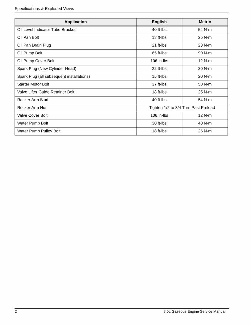
Specifications & Exploded Views
Oil Level Indicator Tube Bracket 40 ft-lbs 54 N-m
Oil Pan Bolt 18 ft-lbs 25 N-m
Oil Pan Drain Plug 21 ft-lbs 28 N-m
Oil Pump Bolt 65 ft-lbs 90 N-m
Oil Pump Cover Bolt 106 in-lbs 12 N-m
Spark Plug (New Cylinder Head) 22 ft-lbs 30 N-m
Spark Plug (all subsequent installations) 15 ft-lbs 20 N-m
Starter Motor Bolt 37 ft-lbs 50 N-m
Valve Lifter Guide Retainer Bolt 18 ft-lbs 25 N-m
Rocker Arm Stud 40 ft-lbs 54 N-m
Rocker Arm Nut Tighten 1/2 to 3/4 Turn Past Preload
Valve Cover Bolt 106 in-lbs 12 N-m
Water Pump Bolt 30 ft-lbs 40 N-m
Water Pump Pulley Bolt 18 ft-lbs 25 N-m
Application English Metric
2 8.0L Gaseous Engine Service Manual
Specifications & Exploded Views
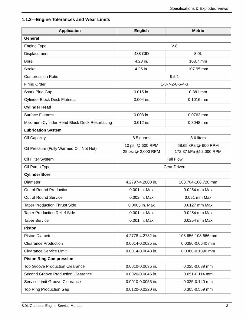
1.1.2—Engine Tolerances and Wear Limits
Application English Metric
General
Engine Type V-8
Displacement 488 CID 8.0L
Bore 4.28 in. 108.7 mm
Stroke 4.25 in. 107.95 mm
Compression Ratio 9.5:1
Firing Order 1-8-7-2-6-5-4-3
Spark Plug Gap 0.015 in. 0.381 mm
Cylinder Block Deck Flatness 0.004 in. 0.1016 mm
Cylinder Head
Surface Flatness 0.003 in. 0.0762 mm
Maximum Cylinder Head Block Deck Resurfacing 0.012 in. 0.3048 mm
Lubrication System
Oil Capacity 8.5 quarts 8.0 liters
Oil Pressure (Fully Warmed Oil, Not Hot)10 psi @ 600 RPM
25 psi @ 2,000 RPM
68.65 kPa @ 600 RPM
172.37 kPa @ 2,000 RPM
Oil Filter System Full Flow
Oil Pump Type Gear Driven
Cylinder Bore
Diameter 4.2797-4.2803 in. 108.704-108.720 mm
Out of Round Production 0.001 in. Max 0.0254 mm Max
Out of Round Service 0.002 in. Max 0.051 mm Max
Taper Production Thrust Side 0.0005 in. Max 0.0127 mm Max
Taper Production Relief Side 0.001 in. Max 0.0254 mm Max
Taper Service 0.001 in. Max 0.0254 mm Max
Piston
Piston Diameter 4.2778-4.2782 in. 108.656-108.666 mm
Clearance Production 0.0014-0.0025 in. 0.0380-0.0640 mm
Clearance Service Limit 0.0014-0.0043 in. 0.0380-0.1090 mm
Piston Ring Compression
Top Groove Production Clearance 0.0010-0.0035 in. 0.025-0.089 mm
Second Groove Production Clearance 0.0020-0.0045 in. 0.051-0.114 mm
Service Limit Groove Clearance 0.0010-0.0055 in. 0.025-0.140 mm
Top Ring Production Gap 0.0120-0.0220 in. 0.305-0.559 mm
8.0L Gaseous Engine Service Manual 3
Specifications & Exploded Views
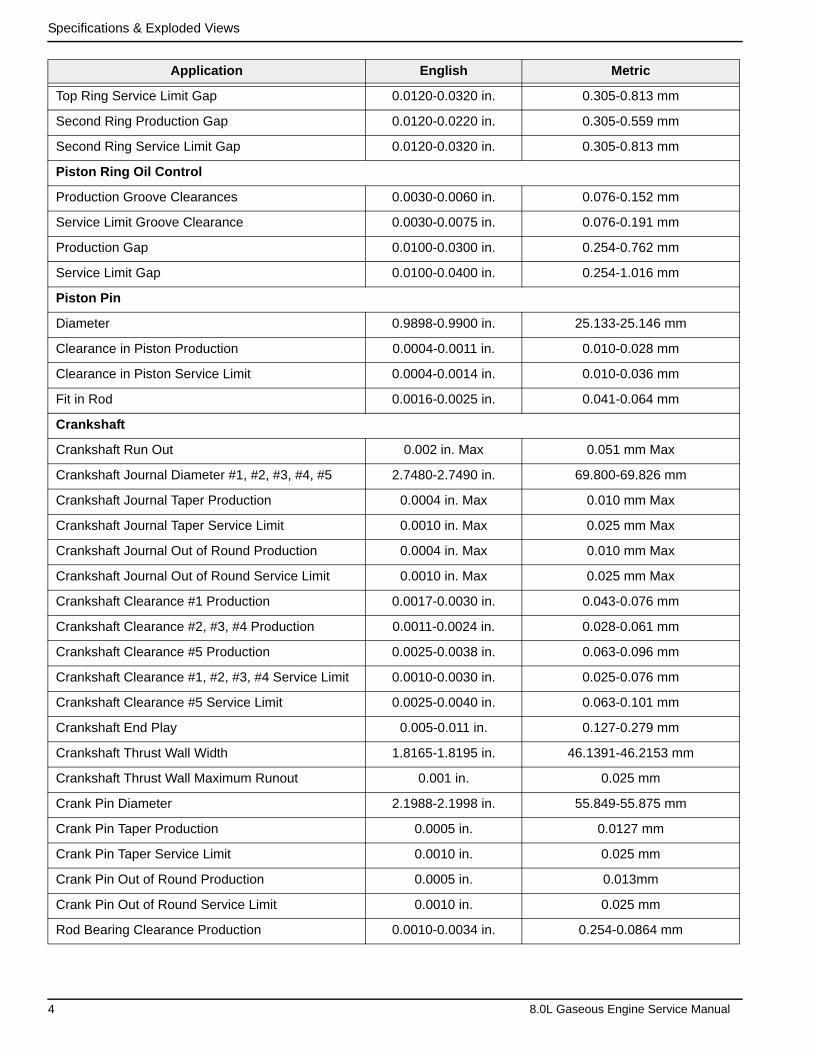
Top Ring Service Limit Gap 0.0120-0.0320 in. 0.305-0.813 mm
Second Ring Production Gap 0.0120-0.0220 in. 0.305-0.559 mm
Second Ring Service Limit Gap 0.0120-0.0320 in. 0.305-0.813 mm
Piston Ring Oil Control
Production Groove Clearances 0.0030-0.0060 in. 0.076-0.152 mm
Service Limit Groove Clearance 0.0030-0.0075 in. 0.076-0.191 mm
Production Gap 0.0100-0.0300 in. 0.254-0.762 mm
Service Limit Gap 0.0100-0.0400 in. 0.254-1.016 mm
Piston Pin
Diameter 0.9898-0.9900 in. 25.133-25.146 mm
Clearance in Piston Production 0.0004-0.0011 in. 0.010-0.028 mm
Clearance in Piston Service Limit 0.0004-0.0014 in. 0.010-0.036 mm
Fit in Rod 0.0016-0.0025 in. 0.041-0.064 mm
Crankshaft
Crankshaft Run Out 0.002 in. Max 0.051 mm Max
Crankshaft Journal Diameter #1, #2, #3, #4, #5 2.7480-2.7490 in. 69.800-69.826 mm
Crankshaft Journal Taper Production 0.0004 in. Max 0.010 mm Max
Crankshaft Journal Taper Service Limit 0.0010 in. Max 0.025 mm Max
Crankshaft Journal Out of Round Production 0.0004 in. Max 0.010 mm Max
Crankshaft Journal Out of Round Service Limit 0.0010 in. Max 0.025 mm Max
Crankshaft Clearance #1 Production 0.0017-0.0030 in. 0.043-0.076 mm
Crankshaft Clearance #2, #3, #4 Production 0.0011-0.0024 in. 0.028-0.061 mm
Crankshaft Clearance #5 Production 0.0025-0.0038 in. 0.063-0.096 mm
Crankshaft Clearance #1, #2, #3, #4 Service Limit 0.0010-0.0030 in. 0.025-0.076 mm
Crankshaft Clearance #5 Service Limit 0.0025-0.0040 in. 0.063-0.101 mm
Crankshaft End Play 0.005-0.011 in. 0.127-0.279 mm
Crankshaft Thrust Wall Width 1.8165-1.8195 in. 46.1391-46.2153 mm
Crankshaft Thrust Wall Maximum Runout 0.001 in. 0.025 mm
Crank Pin Diameter 2.1988-2.1998 in. 55.849-55.875 mm
Crank Pin Taper Production 0.0005 in. 0.0127 mm
Crank Pin Taper Service Limit 0.0010 in. 0.025 mm
Crank Pin Out of Round Production 0.0005 in. 0.013mm
Crank Pin Out of Round Service Limit 0.0010 in. 0.025 mm
Rod Bearing Clearance Production 0.0010-0.0034 in. 0.254-0.0864 mm
Application English Metric
4 8.0L Gaseous Engine Service Manual
Specifications & Exploded Views
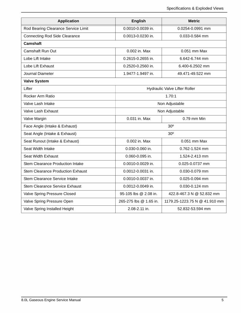
Rod Bearing Clearance Service Limit 0.0010-0.0039 in. 0.0254-0.0991 mm
Connecting Rod Side Clearance 0.0013-0.0230 in. 0.033-0.584 mm
Camshaft
Camshaft Run Out 0.002 in. Max 0.051 mm Max
Lobe Lift Intake 0.2615-0.2655 in. 6.642-6.744 mm
Lobe Lift Exhaust 0.2520-0.2560 in. 6.400-6.2502 mm
Journal Diameter 1.9477-1.9497 in. 49.471-49.522 mm
Valve System
Lifter Hydraulic Valve Lifter Roller
Rocker Arm Ratio 1.70:1
Valve Lash Intake Non Adjustable
Valve Lash Exhaust Non Adjustable
Valve Margin 0.031 in. Max 0.79 mm Min
Face Angle (Intake & Exhaust) 30º
Seat Angle (Intake & Exhaust) 30º
Seat Runout (Intake & Exhaust) 0.002 in. Max 0.051 mm Max
Seat Width Intake 0.030-0.060 in. 0.762-1.524 mm
Seat Width Exhaust 0.060-0.095 in. 1.524-2.413 mm
Stem Clearance Production Intake 0.0010-0.0029 in. 0.025-0.0737 mm
Stem Clearance Production Exhaust 0.0012-0.0031 in. 0.030-0.079 mm
Stem Clearance Service Intake 0.0010-0.0037 in. 0.025-0.094 mm
Stem Clearance Service Exhaust 0.0012-0.0049 in. 0.030-0.124 mm
Valve Spring Pressure Closed 95-105 lbs @ 2.08 in. 422.8-467.3 N @ 52.832 mm
Valve Spring Pressure Open 265-275 lbs @ 1.65 in. 1179.25-1223.75 N @ 41.910 mm
Valve Spring Installed Height 2.08-2.11 in. 52.832-53.594 mm
Application English Metric
8.0L Gaseous Engine Service Manual 5
Specifications & Exploded Views
1.2 — Exploded Views
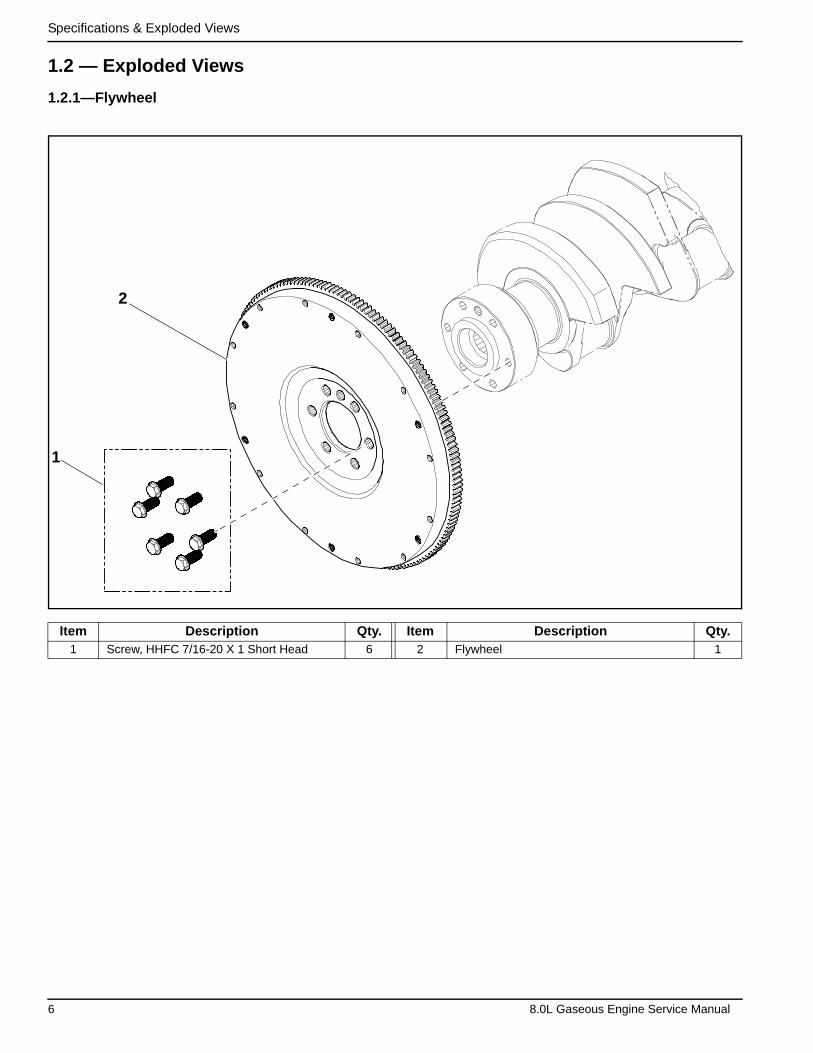
1.2.1—Flywheel
Item Description Qty. Item Description Qty.1 Screw, HHFC 7/16-20 X 1 Short Head 6 2 Flywheel 1
1
2
6 8.0L Gaseous Engine Service Manual
Specifications & Exploded Views
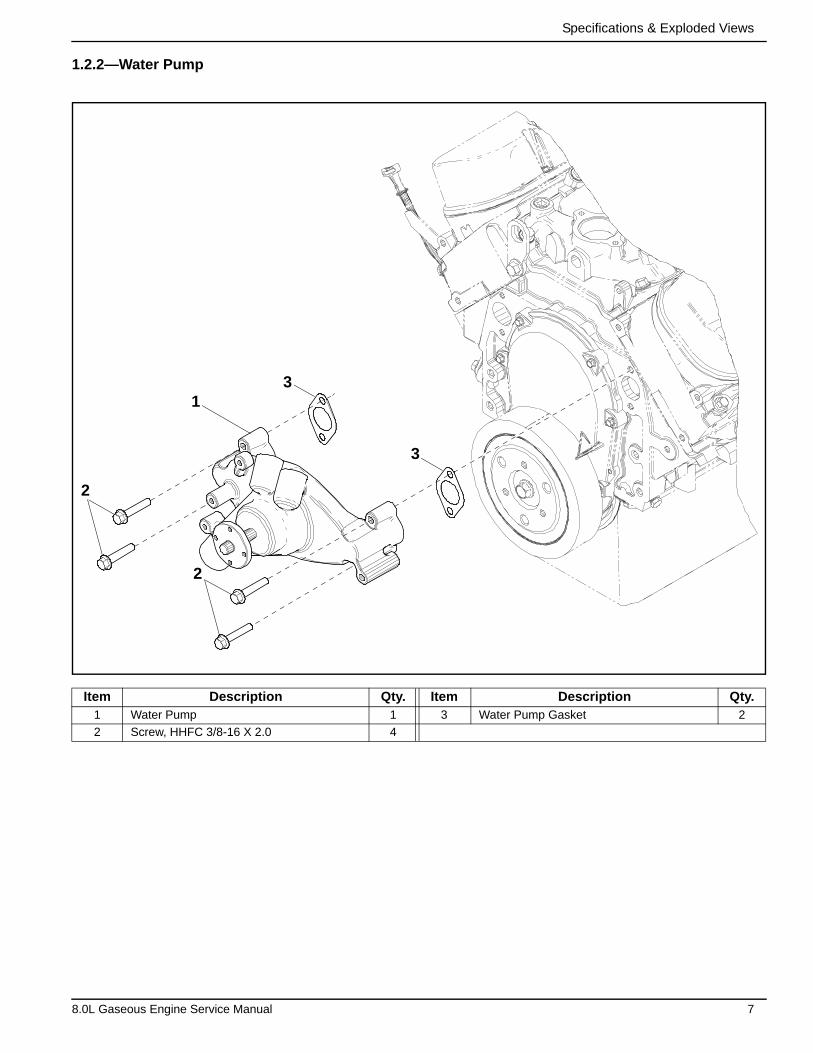
1.2.2—Water Pump
Item Description Qty. Item Description Qty.1 Water Pump 1 3 Water Pump Gasket 2
2 Screw, HHFC 3/8-16 X 2.0 4
1
2
3
3
2
8.0L Gaseous Engine Service Manual 7
Specifications & Exploded Views
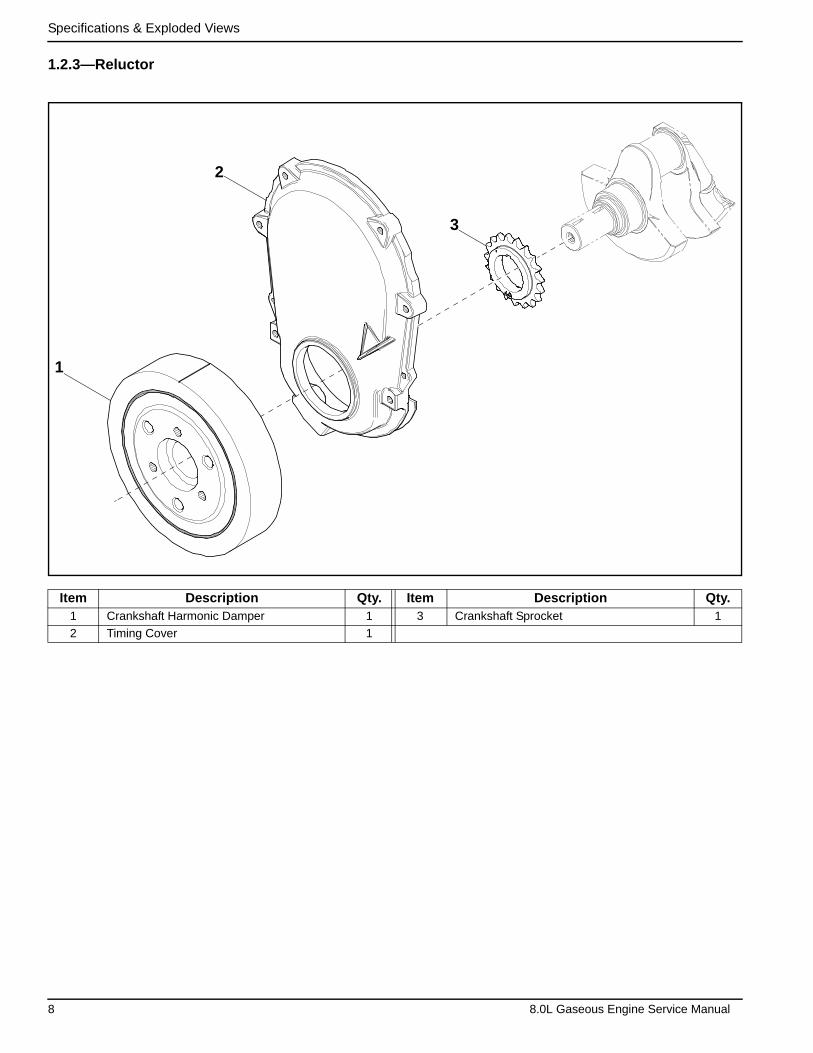
1.2.3—Reluctor
Item Description Qty. Item Description Qty.1 Crankshaft Harmonic Damper 1 3 Crankshaft Sprocket 1
2 Timing Cover 1
1
2
3
8 8.0L Gaseous Engine Service Manual
Specifications & Exploded Views
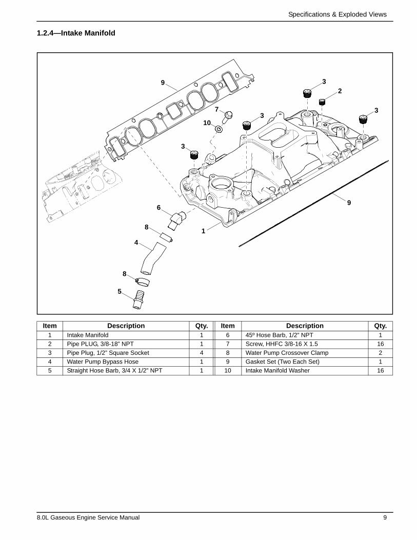
1.2.4—Intake Manifold
Item Description Qty. Item Description Qty.1 Intake Manifold 1 6 45º Hose Barb, 1/2” NPT 1
2 Pipe PLUG, 3/8-18” NPT 1 7 Screw, HHFC 3/8-16 X 1.5 16
3 Pipe Plug, 1/2” Square Socket 4 8 Water Pump Crossover Clamp 2
4 Water Pump Bypass Hose 1 9 Gasket Set (Two Each Set) 1
5 Straight Hose Barb, 3/4 X 1/2” NPT 1 10 Intake Manifold Washer 16
5
8
4
8
6
1
9
3
23
37
10
3
9
8.0L Gaseous Engine Service Manual 9
Specifications & Exploded Views
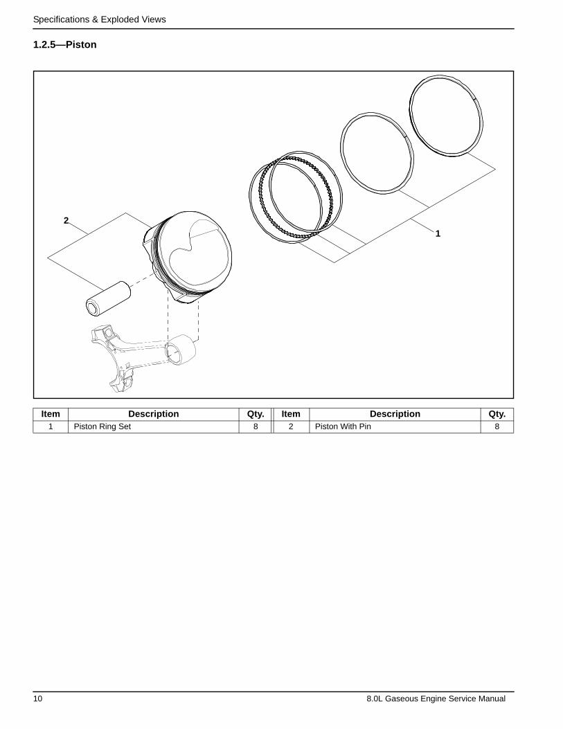
1.2.5—Piston
Item Description Qty. Item Description Qty.1 Piston Ring Set 8 2 Piston With Pin 8
1
2
10 8.0L Gaseous Engine Service Manual
Specifications & Exploded Views
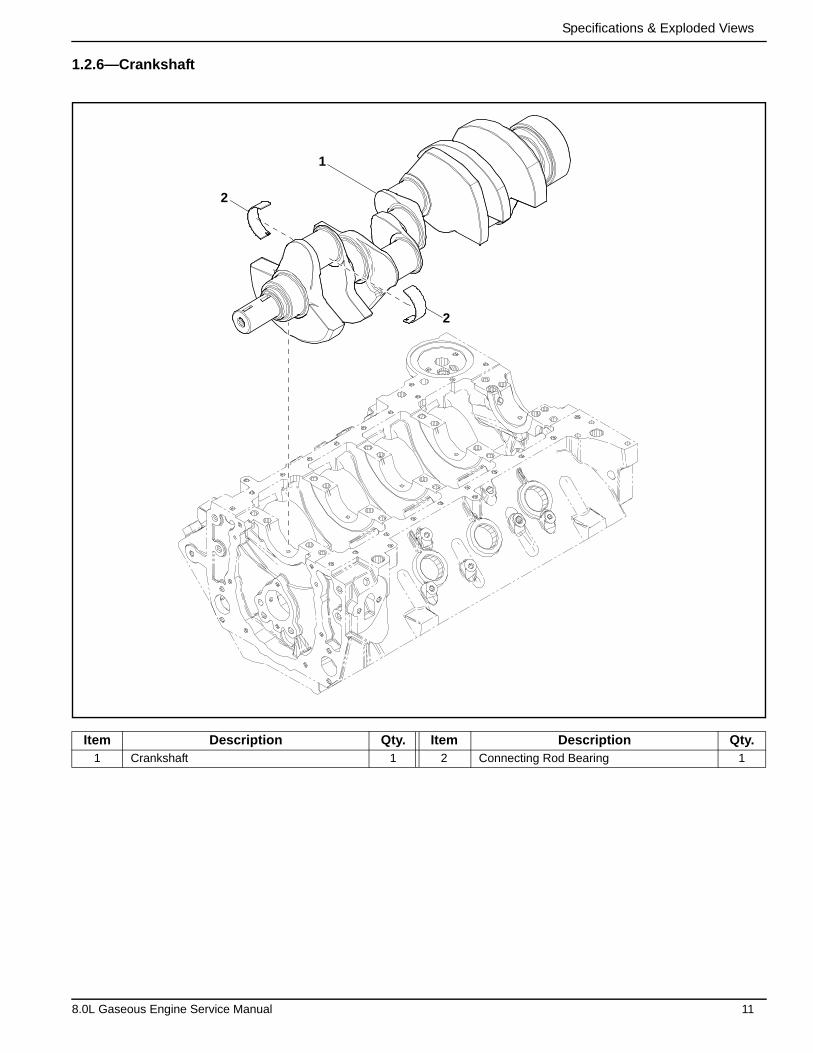
1.2.6—Crankshaft
Item Description Qty. Item Description Qty.1 Crankshaft 1 2 Connecting Rod Bearing 1
1
2
2
8.0L Gaseous Engine Service Manual 11
Specifications & Exploded Views
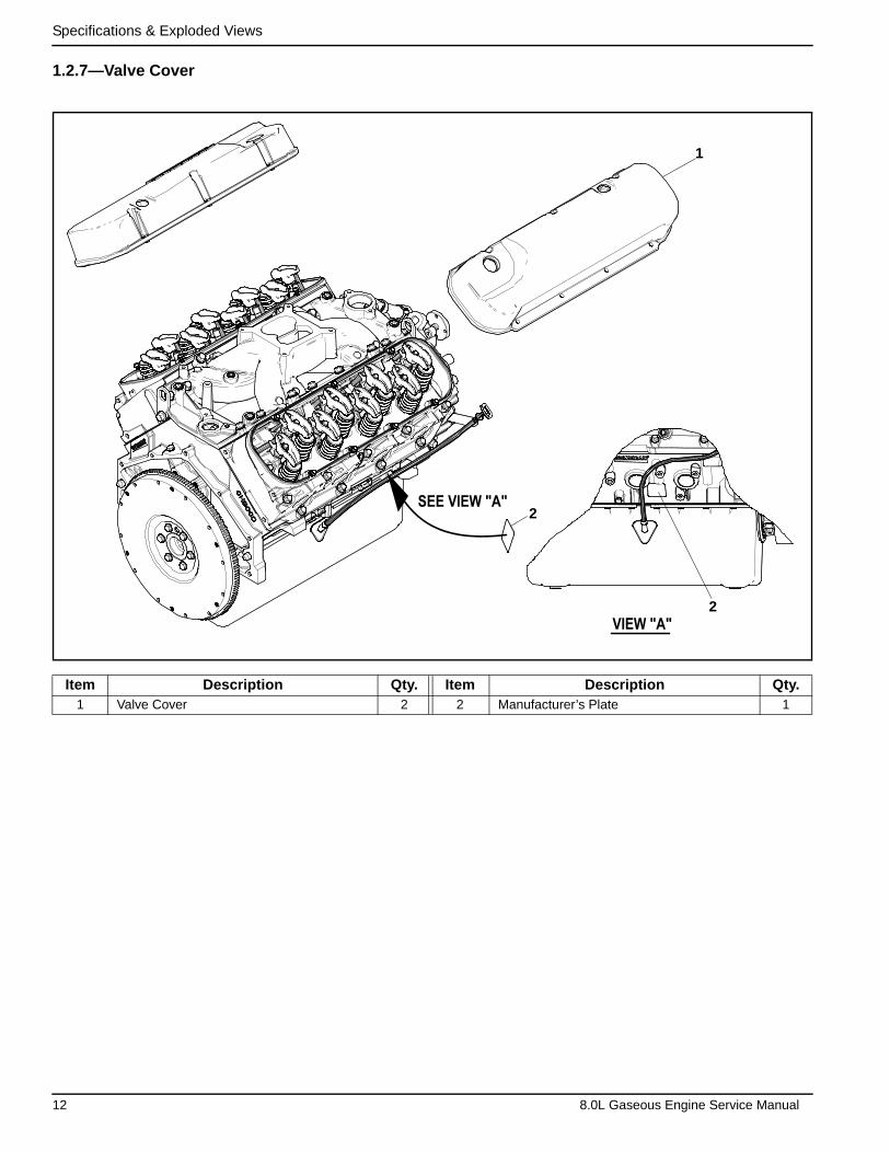
1.2.7—Valve Cover
Item Description Qty. Item Description Qty.1 Valve Cover 2 2 Manufacturer’s Plate 1
1
SEE VIEW "A"
VIEW "A"
1
2
2
12 8.0L Gaseous Engine Service Manual
Specifications & Exploded Views
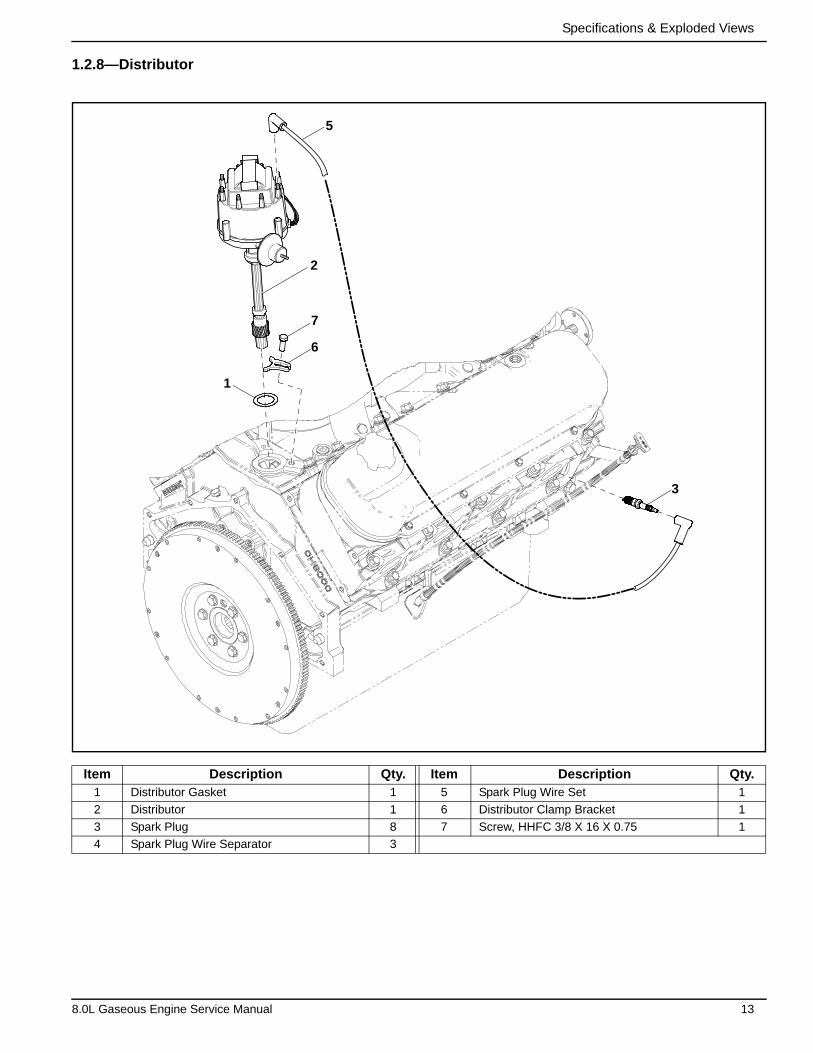
1.2.8—Distributor
Item Description Qty. Item Description Qty.1 Distributor Gasket 1 5 Spark Plug Wire Set 1
2 Distributor 1 6 Distributor Clamp Bracket 1
3 Spark Plug 8 7 Screw, HHFC 3/8 X 16 X 0.75 1
4 Spark Plug Wire Separator 3
1
2
7
6
5
3
8.0L Gaseous Engine Service Manual 13

Specifications & Exploded Views
1.2.9—Engine Block (1 of 3)
Item Description Qty. Item Description Qty.1 Screw 3 12 Pipe Plug 5
2 Camshaft Gear 1 13 Valve Lifter Roller 16
3 Timing Chain 1 14 Valve Lifter Guide 8
4 Timing Cover Gasket 1 15 Screw 24
5 Pipe Plug 2 16 Guide Plate Spyder 1
6 Pipe Plug 4 17 Engine Oil Plug 3
7 Dowel Pin 4 18 Dipstick Tube Weldment 1
8 Crankshaft Seal 1 19 Dipstick Assembly 1
9 Pipe Plug 4 20 Lock Washer 1
10 Cylinder Head Pin 4 21 Screw 3
11 Engine Block Assembly 1
TO "A"
15
16
1314
13
17
18
19
2120
1211
10
75
4
3
2
1
6
8
7
9
14 8.0L Gaseous Engine Service Manual
Specifications & Exploded Views
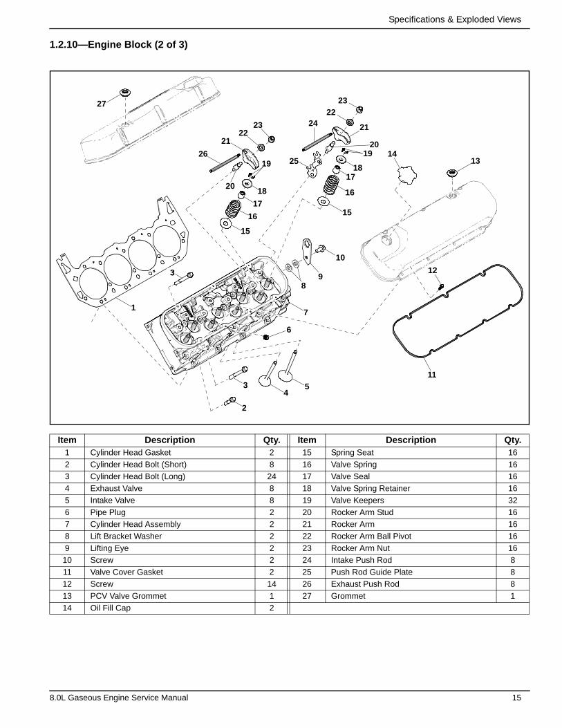
1.2.10—Engine Block (2 of 3)
Item Description Qty. Item Description Qty.1 Cylinder Head Gasket 2 15 Spring Seat 16
2 Cylinder Head Bolt (Short) 8 16 Valve Spring 16
3 Cylinder Head Bolt (Long) 24 17 Valve Seal 16
4 Exhaust Valve 8 18 Valve Spring Retainer 16
5 Intake Valve 8 19 Valve Keepers 32
6 Pipe Plug 2 20 Rocker Arm Stud 16
7 Cylinder Head Assembly 2 21 Rocker Arm 16
8 Lift Bracket Washer 2 22 Rocker Arm Ball Pivot 16
9 Lifting Eye 2 23 Rocker Arm Nut 16
10 Screw 2 24 Intake Push Rod 8
11 Valve Cover Gasket 2 25 Push Rod Guide Plate 8
12 Screw 14 26 Exhaust Push Rod 8
13 PCV Valve Grommet 1 27 Grommet 1
14 Oil Fill Cap 2
3
27
1
3
2
34
5
6
7
89
10
11
12
1314
15
16
1718
1920
21
22
23
24
2526
15
16
17
18
19
20
2122
23
8.0L Gaseous Engine Service Manual 15
Specifications & Exploded Views
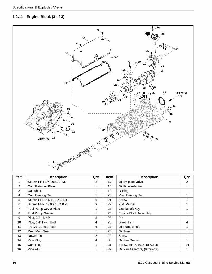
1.2.11—Engine Block (3 of 3)
Item Description Qty. Item Description Qty.1 Screw, PHT 1/4-20X1/2 T30 2 17 Oil By-pass Valve 2
2 Cam Retainer Plate 1 18 Oil Filter Adapter 1
3 Camshaft 1 19 O-Ring 1
4 Cam Bearing Set 1 20 Main Bearing Set 1
5 Screw, HHFD 1/4-20 X 1 1/4 6 21 Screw 1
6 Screw, HHFC 3/8 X16 X 0.75 3 22 Flat Washer 1
7 Fuel Pump Cover Plate 1 23 Crankshaft Key 1
8 Fuel Pump Gasket 1 24 Engine Block Assembly 1
9 Plug, 3/8-18 NP 3 25 Pin 1
10 Plug, 1/4” Hex Head 4 26 Dowel Pin 4
11 Freeze Domed Plug 6 27 Oil Pump Shaft 1
12 Rear Main Seal 1 28 Oil Pump 1
13 Dowel Pin 2 29 Screw 1
14 Pipe Plug 4 30 Oil Pan Gasket 1
15 Cam Plug 1 31 Screw, HHFC 5/16-18 X.625 24
16 Pipe Plug 5 32 Oil Pan Assembly (8 Quarts) 1
"A"
SEE VIEW"A"
VIEW "A"
12
3
4
5
678
9
10
11
12
1314
15
16
13
17
18
19 2016
1020
2122
23
20
2420
25
2624
27
28
29
30
31
9
32
9
16 8.0L Gaseous Engine Service Manual
Specifications & Exploded Views
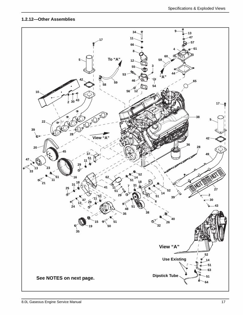
1.2.12—Other Assemblies
39
22
2045
28
10
62
38
49
27
42
538
17
2836
65
392
30
43
35
4851
19
35
15 5150
5114
52
5114
52
51
51
51
51
37
11
11
11
11
21
29
29
29
4026
32
6
7 3118
3313 23
47
2531
18
41
16
2 30 43
2413
47
5
17
5859
To “A”
“A”
View “A”
View “A”
Use Existing
Dipstick Tube
9
56 12
42
54
3
5960
4
1347
57
61
44
46
53
55
12
66
11
34
8
52
14
51
63
51
64See NOTES on next page.
8.0L Gaseous Engine Service Manual 17

Specifications & Exploded Views
NOTES:
(1) Apply Medium Strength (Blue) Threadlocker to threads before installation.
(2) Torque Specifications:
• Item #9 - 20 ft-lbs
• Item #17 – 31 ft-lbs
• Item #34 –27 ft-lbs
• Item #39 – 20 ft-lbs
Item Description Qty. Item Description Qty.1 Engine 1 (2) 34 Screw, Hex Head 3/8-16 X 3” 2
2 Flat Washer, M6 12 (1) 35 DC Alternator Without Pulley 1
3 Pipe Plug, 1/8” Square Head 1 36 Oil Filter 1
4 Intake Assembly Adaptor 1 37 Signal Conditioner Bracket 1
5 Exhaust Outlet Pipe Assembly 2 38 Tensioner 2
6 Belt Tensioner Bracket 1 (2) 39 Screw, Socket Head 3/8-16X1 16
7 Screw, Hex Head 7/16-14 X1 G5 1 40 Flat Washer, 1/2” 1
8 Thermostat Housing 1 41 DC Alternator Bracket 1
(2) 9 Screw, Hex Head 5/16-18X1-1/4 G5 4 42 Exhaust Gasket 2
10 Heat Shield (Right Side) 1 43 Screw, Hex Head M6-1.0 X12 12
11 Lock Washer, 3/8” 8 44 Intake Adaptor Gasket 1
12 Thermostat Gasket 2 45 Water Pump Pulley 1
13 Lock Washer, M8-5/16 9 46 Thermostat Housing 1
14 Lock Washer, M10 3 47 Flat Washer, 5/16-M8 9
15 DC Alternator Spacer 1 48 Screw, Hex Head M10-1.5X70 C8.8 1
16 Crankshaft Pulley Assembly 1 49 Exhaust Manifold 1
(2) 17 Screw, Socket Head M10-1.5 X 25 8 50 Screw, Hex Head M10-1.5X50 C8.8 1
18 Flat Washer, 7/16” 2 51 Flat Washer, 3/8-M10 13
19 DC Alternator Pulley, 80” OD 1 52 Hex Nut, M10-1.5 G8 3
20 Serpentine Belt, 46.48" 1 53 Temperature Sender 1
(1) 21 Screw, Hex Head 3/8-24 X 1-1/2 G8 3 54 Pipe Plug, 1/2” Square Head 1
22 Exhaust Manifold 1 55 Thermostat 1
23 Fan Spacer 1 56 Pipe Plug, 3/8” Square Head 1
24 Screw, Hex Head M8-1.25X25 C8.8 1 57 Signal Conditioner Bracket 1
25 Screw, Hex Head 7/16-14 X 3/4 G5 1 58 PCV Valve 1
26 Lock Washer, 1/2 1 59 Hose, 3/8 ID Single Braid (12" LG) 1
27 Heat Shield (Left Side) 1 60 Barbed STR 1/4” NPT X 3/8 1
28 Exhaust Manifold Gasket 2 61 Pipe Plug, 1/4” Square Head 1
29 Screw, Hex Head 3/8-16 X 3/4 G8 3 62 DC Alternator Bracket Stiffener 1
30 Lock Washer, M6 12 63 Dipstick Bracket 1
31 Lock Washer 2 64 Screw, Hex Head M10-1.5X25 C8.8 1
32 Screw, Hex Head 1/2-13X1-1/4 G5 1 65 Refer to Owners Decal 1
(1) 33 Screw, Hex Head 5/16-24X2-1/2 G5 4
18 8.0L Gaseous Engine Service Manual
Section 2 Diagnostics
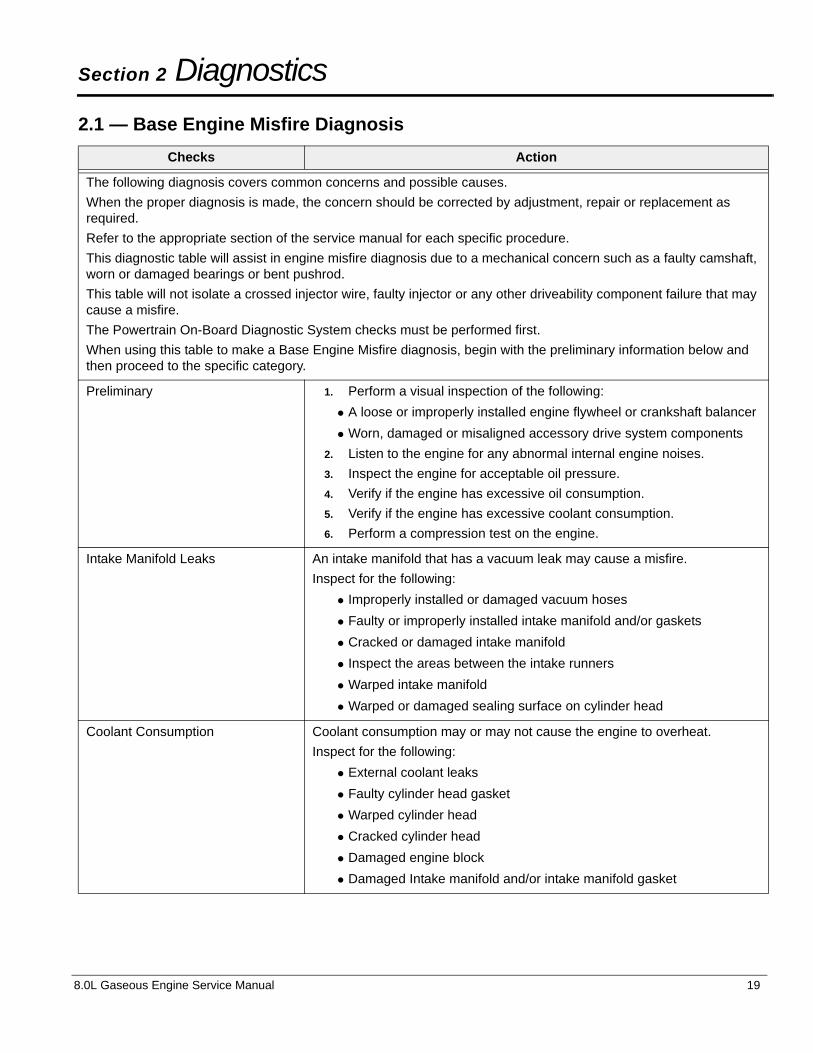
2.1 — Base Engine Misfire Diagnosis
Checks Action
The following diagnosis covers common concerns and possible causes.
When the proper diagnosis is made, the concern should be corrected by adjustment, repair or replacement as required.
Refer to the appropriate section of the service manual for each specific procedure.
This diagnostic table will assist in engine misfire diagnosis due to a mechanical concern such as a faulty camshaft, worn or damaged bearings or bent pushrod.
This table will not isolate a crossed injector wire, faulty injector or any other driveability component failure that may cause a misfire.
The Powertrain On-Board Diagnostic System checks must be performed first.
When using this table to make a Base Engine Misfire diagnosis, begin with the preliminary information below and then proceed to the specific category.
Preliminary 1. Perform a visual inspection of the following:
• A loose or improperly installed engine flywheel or crankshaft balancer
• Worn, damaged or misaligned accessory drive system components
2. Listen to the engine for any abnormal internal engine noises.
3. Inspect the engine for acceptable oil pressure.
4. Verify if the engine has excessive oil consumption.
5. Verify if the engine has excessive coolant consumption.
6. Perform a compression test on the engine.
Intake Manifold Leaks An intake manifold that has a vacuum leak may cause a misfire.
Inspect for the following:
• Improperly installed or damaged vacuum hoses
• Faulty or improperly installed intake manifold and/or gaskets
• Cracked or damaged intake manifold
• Inspect the areas between the intake runners
• Warped intake manifold
• Warped or damaged sealing surface on cylinder head
Coolant Consumption Coolant consumption may or may not cause the engine to overheat.
Inspect for the following:
• External coolant leaks
• Faulty cylinder head gasket
• Warped cylinder head
• Cracked cylinder head
• Damaged engine block
• Damaged Intake manifold and/or intake manifold gasket
8.0L Gaseous Engine Service Manual 19
Diagnostics
Checks Action
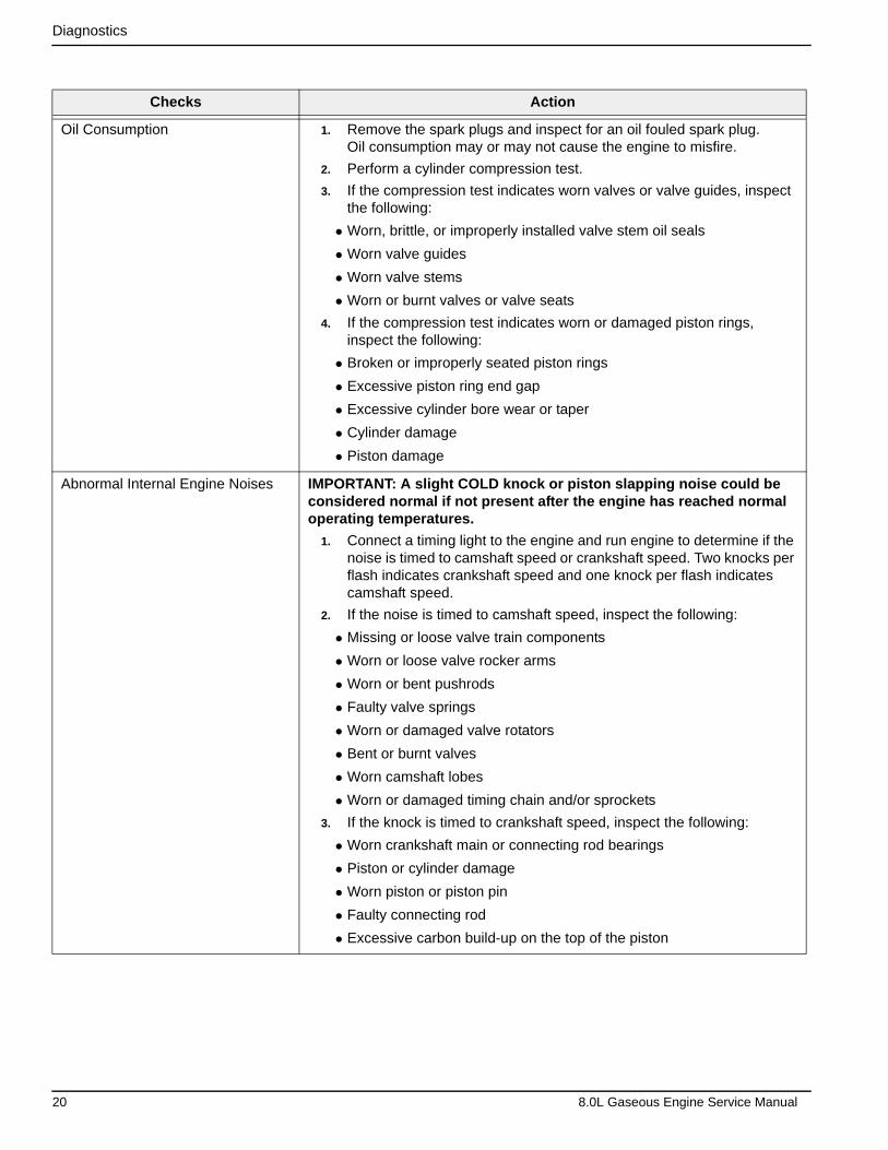
Oil Consumption 1. Remove the spark plugs and inspect for an oil fouled spark plug. Oil consumption may or may not cause the engine to misfire.
2. Perform a cylinder compression test.
3. If the compression test indicates worn valves or valve guides, inspect the following:
• Worn, brittle, or improperly installed valve stem oil seals
• Worn valve guides
• Worn valve stems
• Worn or burnt valves or valve seats
4. If the compression test indicates worn or damaged piston rings, inspect the following:
• Broken or improperly seated piston rings
• Excessive piston ring end gap
• Excessive cylinder bore wear or taper
• Cylinder damage
• Piston damage
Abnormal Internal Engine Noises IMPORTANT: A slight COLD knock or piston slapping noise could be considered normal if not present after the engine has reached normal operating temperatures.
1. Connect a timing light to the engine and run engine to determine if the noise is timed to camshaft speed or crankshaft speed. Two knocks per flash indicates crankshaft speed and one knock per flash indicates camshaft speed.
2. If the noise is timed to camshaft speed, inspect the following:
• Missing or loose valve train components
• Worn or loose valve rocker arms
• Worn or bent pushrods
• Faulty valve springs
• Worn or damaged valve rotators
• Bent or burnt valves
• Worn camshaft lobes
• Worn or damaged timing chain and/or sprockets
3. If the knock is timed to crankshaft speed, inspect the following:
• Worn crankshaft main or connecting rod bearings
• Piston or cylinder damage
• Worn piston or piston pin
• Faulty connecting rod
• Excessive carbon build-up on the top of the piston
20 8.0L Gaseous Engine Service Manual
Diagnostics
2.2 — Engine Noise Diagnosis
Checks Action
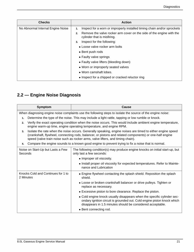
No Abnormal Internal Engine Noise 1. Inspect for a worn or improperly installed timing chain and/or sprockets
2. Remove the valve rocker arm cover on the side of the engine with the cylinder that is misfiring.
3. Inspect for the following:
• Loose valve rocker arm bolts
• Bent push rods
• Faulty valve springs
• Faulty valve lifters (bleeding down)
• Worn or improperly seated valves
• Worn camshaft lobes.
• Inspect for a chipped or cracked reluctor ring
Symptom Cause
When diagnosing engine noise complaints use the following steps to isolate the source of the engine noise:
1. Determine the type of the noise. This may include a light rattle, tapping or low rumble or knock.
2. Verify the exact operating condition when the noise occurs. This would include ambient engine temperature, engine warm-up time, engine operating temperature, and engine RPM.
3. Isolate the rate when the noise occurs. Generally speaking, engine noises are timed to either engine speed (crankshaft, flywheel, connecting rods, balancer, or pistons and related components) or one-half engine speed (valve train noise such as rocker arms, valve lifters, and timing chain).
4. Compare the engine sounds to a known good engine to prevent trying to fix a noise that is normal.
Noise on Start-Up but Lasts a Few Seconds
The following condition(s) may produce engine knocks on initial start-up, but only last a few seconds:
• Improper oil viscosity.
• Install proper oil viscosity for expected temperatures. Refer to Mainte-nance and Lubrication
Knocks Cold and Continues for 1 to 2 Minutes
• Engine flywheel contacting the splash shield. Reposition the splash shield.
• Loose or broken crankshaft balancer or drive pulleys. Tighten or replace as necessary.
• Excessive piston to bore clearance. Replace the piston.
• Cold engine knock usually disappears when the specific cylinder sec-ondary ignition circuit is grounded out. Cold engine piston knock which disappears in 1.5 minutes should be considered acceptable.
• Bent connecting rod.
8.0L Gaseous Engine Service Manual 21
Diagnostics
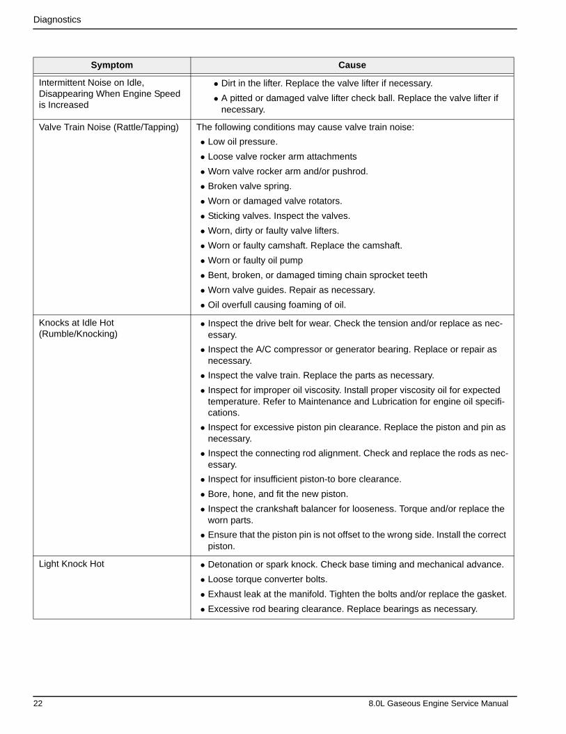
Symptom Cause
Intermittent Noise on Idle, Disappearing When Engine Speed is Increased
• Dirt in the lifter. Replace the valve lifter if necessary.
• A pitted or damaged valve lifter check ball. Replace the valve lifter if necessary.
Valve Train Noise (Rattle/Tapping) The following conditions may cause valve train noise:
• Low oil pressure.
• Loose valve rocker arm attachments
• Worn valve rocker arm and/or pushrod.
• Broken valve spring.
• Worn or damaged valve rotators.
• Sticking valves. Inspect the valves.
• Worn, dirty or faulty valve lifters.
• Worn or faulty camshaft. Replace the camshaft.
• Worn or faulty oil pump
• Bent, broken, or damaged timing chain sprocket teeth
• Worn valve guides. Repair as necessary.
• Oil overfull causing foaming of oil.
Knocks at Idle Hot (Rumble/Knocking)
• Inspect the drive belt for wear. Check the tension and/or replace as nec-essary.
• Inspect the A/C compressor or generator bearing. Replace or repair as necessary.
• Inspect the valve train. Replace the parts as necessary.
• Inspect for improper oil viscosity. Install proper viscosity oil for expected temperature. Refer to Maintenance and Lubrication for engine oil specifi-cations.
• Inspect for excessive piston pin clearance. Replace the piston and pin as necessary.
• Inspect the connecting rod alignment. Check and replace the rods as nec-essary.
• Inspect for insufficient piston-to bore clearance.
• Bore, hone, and fit the new piston.
• Inspect the crankshaft balancer for looseness. Torque and/or replace the worn parts.
• Ensure that the piston pin is not offset to the wrong side. Install the correct piston.
Light Knock Hot • Detonation or spark knock. Check base timing and mechanical advance.
• Loose torque converter bolts.
• Exhaust leak at the manifold. Tighten the bolts and/or replace the gasket.
• Excessive rod bearing clearance. Replace bearings as necessary.
22 8.0L Gaseous Engine Service Manual
Diagnostics
Symptom Cause
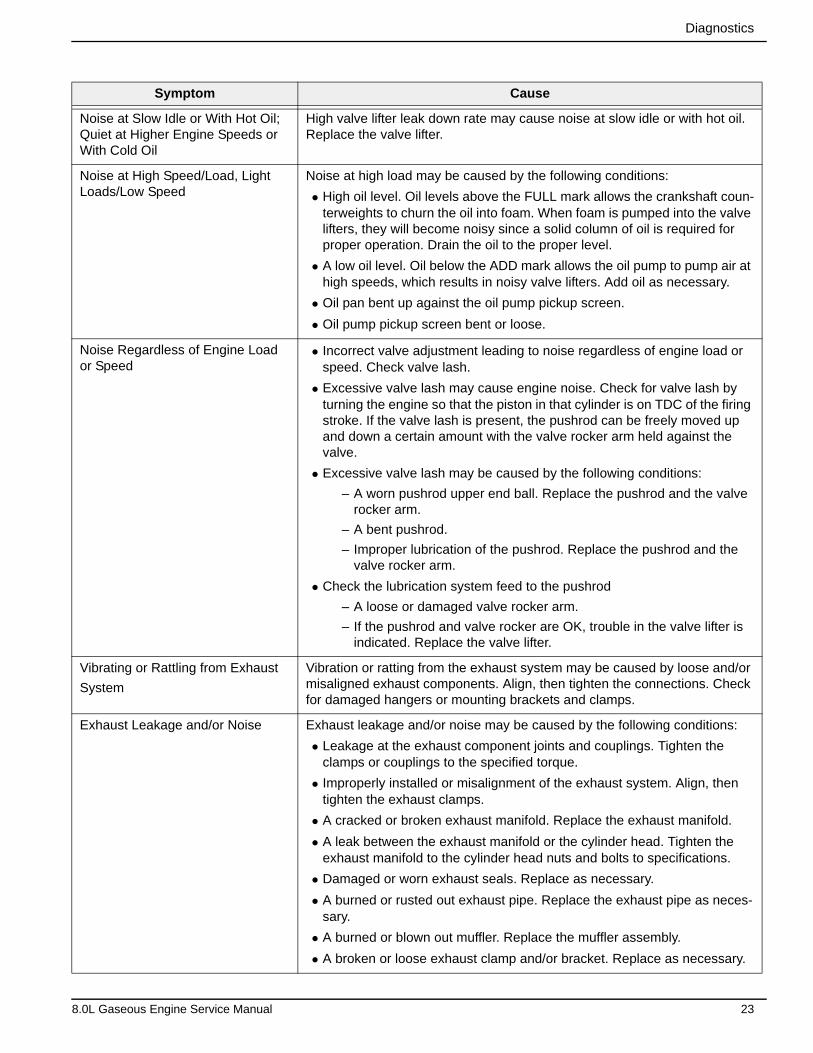
Noise at Slow Idle or With Hot Oil; Quiet at Higher Engine Speeds or With Cold Oil
High valve lifter leak down rate may cause noise at slow idle or with hot oil. Replace the valve lifter.
Noise at High Speed/Load, Light Loads/Low Speed
Noise at high load may be caused by the following conditions:
• High oil level. Oil levels above the FULL mark allows the crankshaft coun-terweights to churn the oil into foam. When foam is pumped into the valve lifters, they will become noisy since a solid column of oil is required for proper operation. Drain the oil to the proper level.
• A low oil level. Oil below the ADD mark allows the oil pump to pump air at high speeds, which results in noisy valve lifters. Add oil as necessary.
• Oil pan bent up against the oil pump pickup screen.
• Oil pump pickup screen bent or loose.
Noise Regardless of Engine Load or Speed
• Incorrect valve adjustment leading to noise regardless of engine load or speed. Check valve lash.
• Excessive valve lash may cause engine noise. Check for valve lash by turning the engine so that the piston in that cylinder is on TDC of the firing stroke. If the valve lash is present, the pushrod can be freely moved up and down a certain amount with the valve rocker arm held against the valve.
• Excessive valve lash may be caused by the following conditions:
– A worn pushrod upper end ball. Replace the pushrod and the valve rocker arm.
– A bent pushrod.
– Improper lubrication of the pushrod. Replace the pushrod and the valve rocker arm.
• Check the lubrication system feed to the pushrod
– A loose or damaged valve rocker arm.
– If the pushrod and valve rocker are OK, trouble in the valve lifter is indicated. Replace the valve lifter.
Vibrating or Rattling from Exhaust
System
Vibration or ratting from the exhaust system may be caused by loose and/or misaligned exhaust components. Align, then tighten the connections. Check for damaged hangers or mounting brackets and clamps.
Exhaust Leakage and/or Noise Exhaust leakage and/or noise may be caused by the following conditions:
• Leakage at the exhaust component joints and couplings. Tighten the clamps or couplings to the specified torque.
• Improperly installed or misalignment of the exhaust system. Align, then tighten the exhaust clamps.
• A cracked or broken exhaust manifold. Replace the exhaust manifold.
• A leak between the exhaust manifold or the cylinder head. Tighten the exhaust manifold to the cylinder head nuts and bolts to specifications.
• Damaged or worn exhaust seals. Replace as necessary.
• A burned or rusted out exhaust pipe. Replace the exhaust pipe as neces-sary.
• A burned or blown out muffler. Replace the muffler assembly.
• A broken or loose exhaust clamp and/or bracket. Replace as necessary.
8.0L Gaseous Engine Service Manual 23
Diagnostics
2.3 — General Information
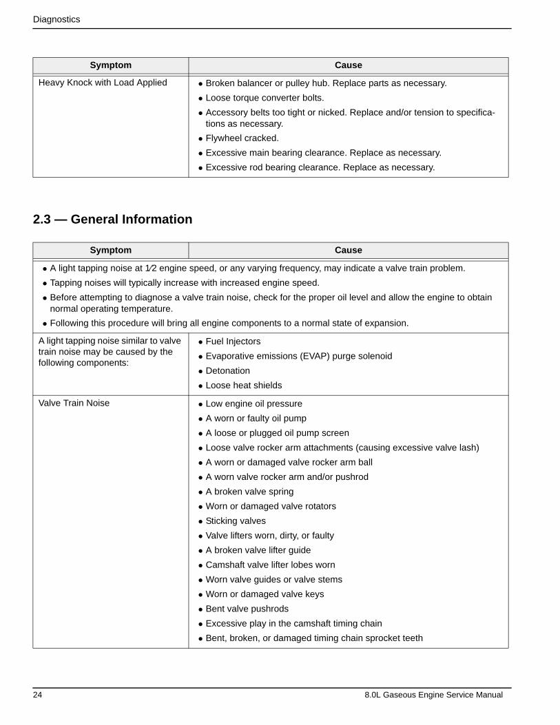
Symptom Cause
Heavy Knock with Load Applied • Broken balancer or pulley hub. Replace parts as necessary.
• Loose torque converter bolts.
• Accessory belts too tight or nicked. Replace and/or tension to specifica-tions as necessary.
• Flywheel cracked.
• Excessive main bearing clearance. Replace as necessary.
• Excessive rod bearing clearance. Replace as necessary.
Symptom Cause
• A light tapping noise at 1⁄2 engine speed, or any varying frequency, may indicate a valve train problem.
• Tapping noises will typically increase with increased engine speed.
• Before attempting to diagnose a valve train noise, check for the proper oil level and allow the engine to obtain normal operating temperature.
• Following this procedure will bring all engine components to a normal state of expansion.
A light tapping noise similar to valve train noise may be caused by the following components:
• Fuel Injectors
• Evaporative emissions (EVAP) purge solenoid
• Detonation
• Loose heat shields
Valve Train Noise • Low engine oil pressure
• A worn or faulty oil pump
• A loose or plugged oil pump screen
• Loose valve rocker arm attachments (causing excessive valve lash)
• A worn or damaged valve rocker arm ball
• A worn valve rocker arm and/or pushrod
• A broken valve spring
• Worn or damaged valve rotators
• Sticking valves
• Valve lifters worn, dirty, or faulty
• A broken valve lifter guide
• Camshaft valve lifter lobes worn
• Worn valve guides or valve stems
• Worn or damaged valve keys
• Bent valve pushrods
• Excessive play in the camshaft timing chain
• Bent, broken, or damaged timing chain sprocket teeth
24 8.0L Gaseous Engine Service Manual
Diagnostics
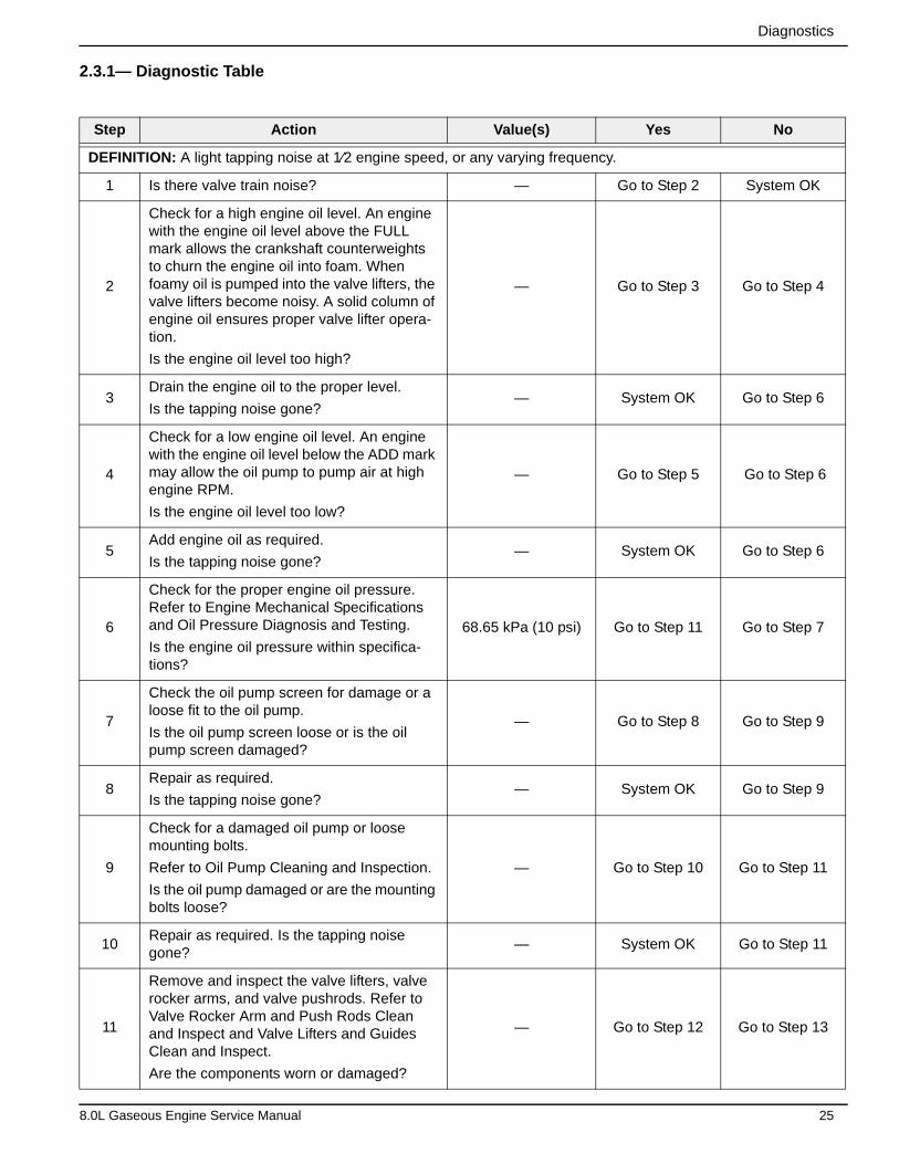
2.3.1— Diagnostic Table
Step Action Value(s) Yes No
DEFINITION: A light tapping noise at 1⁄2 engine speed, or any varying frequency.
1 Is there valve train noise? — Go to Step 2 System OK
2
Check for a high engine oil level. An engine with the engine oil level above the FULL mark allows the crankshaft counterweights to churn the engine oil into foam. When foamy oil is pumped into the valve lifters, the valve lifters become noisy. A solid column of engine oil ensures proper valve lifter opera-tion.
Is the engine oil level too high?
— Go to Step 3 Go to Step 4
3Drain the engine oil to the proper level.
Is the tapping noise gone?— System OK Go to Step 6
4
Check for a low engine oil level. An engine with the engine oil level below the ADD mark may allow the oil pump to pump air at high engine RPM.
Is the engine oil level too low?
— Go to Step 5 Go to Step 6
5Add engine oil as required.
Is the tapping noise gone?— System OK Go to Step 6
6
Check for the proper engine oil pressure. Refer to Engine Mechanical Specifications and Oil Pressure Diagnosis and Testing.
Is the engine oil pressure within specifica-tions?
68.65 kPa (10 psi) Go to Step 11 Go to Step 7
7
Check the oil pump screen for damage or a loose fit to the oil pump.
Is the oil pump screen loose or is the oil pump screen damaged?
— Go to Step 8 Go to Step 9
8Repair as required.
Is the tapping noise gone?— System OK Go to Step 9
9
Check for a damaged oil pump or loose mounting bolts.
Refer to Oil Pump Cleaning and Inspection.
Is the oil pump damaged or are the mounting bolts loose?
— Go to Step 10 Go to Step 11
10Repair as required. Is the tapping noise gone?
— System OK Go to Step 11
11
Remove and inspect the valve lifters, valve rocker arms, and valve pushrods. Refer to Valve Rocker Arm and Push Rods Clean and Inspect and Valve Lifters and Guides Clean and Inspect.
Are the components worn or damaged?
— Go to Step 12 Go to Step 13
8.0L Gaseous Engine Service Manual 25
Diagnostics
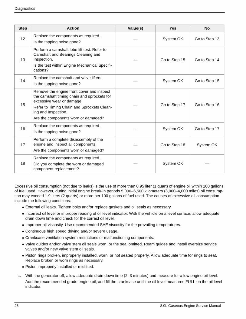
Excessive oil consumption (not due to leaks) is the use of more than 0.95 liter (1 quart) of engine oil within 100 gallons of fuel used. However, during initial engine break-in periods 5,000–6,500 kilometers (3,000–4,000 miles) oil consump-tion may exceed 1.9 liters (2 quarts) or more per 100 gallons of fuel used. The causes of excessive oil consumption include the following conditions:
• External oil leaks. Tighten bolts and/or replace gaskets and oil seals as necessary.
• Incorrect oil level or improper reading of oil level indicator. With the vehicle on a level surface, allow adequate drain down time and check for the correct oil level.
• Improper oil viscosity. Use recommended SAE viscosity for the prevailing temperatures.
• Continuous high speed driving and/or severe usage.
• Crankcase ventilation system restrictions or malfunctioning components.
• Valve guides and/or valve stem oil seals worn, or the seal omitted. Ream guides and install oversize service valves and/or new valve stem oil seals.
• Piston rings broken, improperly installed, worn, or not seated properly. Allow adequate time for rings to seat. Replace broken or worn rings as necessary.
• Piston improperly installed or misfitted.
1. With the generator off, allow adequate drain down time (2–3 minutes) and measure for a low engine oil level.
Add the recommended grade engine oil, and fill the crankcase until the oil level measures FULL on the oil level indicator.
Step Action Value(s) Yes No
12Replace the components as required.
Is the tapping noise gone?— System OK Go to Step 13
13
Perform a camshaft lobe lift test. Refer to Camshaft and Bearings Cleaning and Inspection.
Is the test within Engine Mechanical Specifi-cations?
— Go to Step 15 Go to Step 14
14Replace the camshaft and valve lifters.
Is the tapping noise gone?— System OK Go to Step 15
15
Remove the engine front cover and inspect the camshaft timing chain and sprockets for excessive wear or damage.
Refer to Timing Chain and Sprockets Clean-ing and Inspection.
Are the components worn or damaged?
— Go to Step 17 Go to Step 16
16Replace the components as required.
Is the tapping noise gone?— System OK Go to Step 17
17Perform a complete disassembly of the engine and inspect all components.
Are the components worn or damaged?— Go to Step 18 System OK
18Replace the components as required.
Did you complete the worn or damaged component replacement?
— System OK —
26 8.0L Gaseous Engine Service Manual
Diagnostics
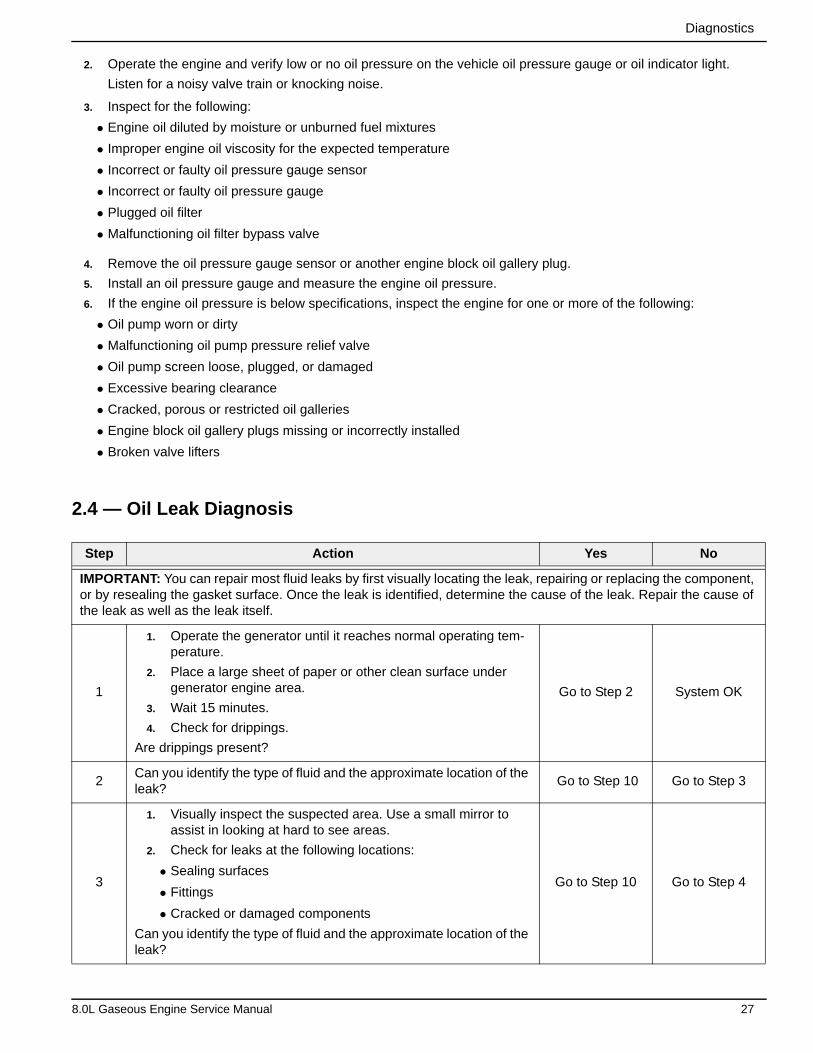
2. Operate the engine and verify low or no oil pressure on the vehicle oil pressure gauge or oil indicator light.
Listen for a noisy valve train or knocking noise.
3. Inspect for the following:
• Engine oil diluted by moisture or unburned fuel mixtures
• Improper engine oil viscosity for the expected temperature
• Incorrect or faulty oil pressure gauge sensor
• Incorrect or faulty oil pressure gauge
• Plugged oil filter
• Malfunctioning oil filter bypass valve
4. Remove the oil pressure gauge sensor or another engine block oil gallery plug.
5. Install an oil pressure gauge and measure the engine oil pressure.
6. If the engine oil pressure is below specifications, inspect the engine for one or more of the following:
• Oil pump worn or dirty
• Malfunctioning oil pump pressure relief valve
• Oil pump screen loose, plugged, or damaged
• Excessive bearing clearance
• Cracked, porous or restricted oil galleries
• Engine block oil gallery plugs missing or incorrectly installed
• Broken valve lifters
2.4 — Oil Leak Diagnosis
Step Action Yes No
IMPORTANT: You can repair most fluid leaks by first visually locating the leak, repairing or replacing the component, or by resealing the gasket surface. Once the leak is identified, determine the cause of the leak. Repair the cause of the leak as well as the leak itself.
1
1. Operate the generator until it reaches normal operating tem-perature.
2. Place a large sheet of paper or other clean surface under generator engine area.
3. Wait 15 minutes.
4. Check for drippings.
Are drippings present?
Go to Step 2 System OK
2Can you identify the type of fluid and the approximate location of the leak?
Go to Step 10 Go to Step 3
3
1. Visually inspect the suspected area. Use a small mirror to assist in looking at hard to see areas.
2. Check for leaks at the following locations:
• Sealing surfaces
• Fittings
• Cracked or damaged components
Can you identify the type of fluid and the approximate location of the leak?
Go to Step 10 Go to Step 4
8.0L Gaseous Engine Service Manual 27
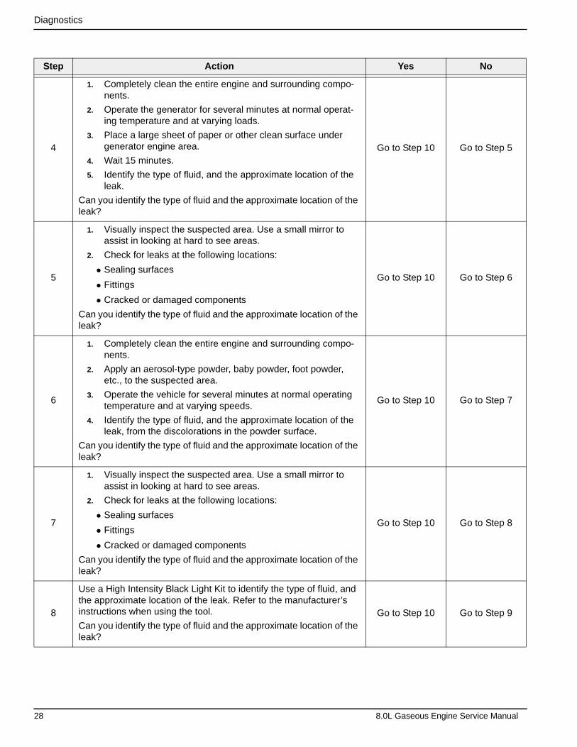
Diagnostics
Step Action Yes No
4
1. Completely clean the entire engine and surrounding compo-nents.
2. Operate the generator for several minutes at normal operat-ing temperature and at varying loads.
3. Place a large sheet of paper or other clean surface under generator engine area.
4. Wait 15 minutes.
5. Identify the type of fluid, and the approximate location of the leak.
Can you identify the type of fluid and the approximate location of the leak?
Go to Step 10 Go to Step 5
5
1. Visually inspect the suspected area. Use a small mirror to assist in looking at hard to see areas.
2. Check for leaks at the following locations:
• Sealing surfaces
• Fittings
• Cracked or damaged components
Can you identify the type of fluid and the approximate location of the leak?
Go to Step 10 Go to Step 6
6
1. Completely clean the entire engine and surrounding compo-nents.
2. Apply an aerosol-type powder, baby powder, foot powder, etc., to the suspected area.
3. Operate the vehicle for several minutes at normal operating temperature and at varying speeds.
4. Identify the type of fluid, and the approximate location of the leak, from the discolorations in the powder surface.
Can you identify the type of fluid and the approximate location of the leak?
Go to Step 10 Go to Step 7
7
1. Visually inspect the suspected area. Use a small mirror to assist in looking at hard to see areas.
2. Check for leaks at the following locations:
• Sealing surfaces
• Fittings
• Cracked or damaged components
Can you identify the type of fluid and the approximate location of the leak?
Go to Step 10 Go to Step 8
8
Use a High Intensity Black Light Kit to identify the type of fluid, and the approximate location of the leak. Refer to the manufacturer’s instructions when using the tool.
Can you identify the type of fluid and the approximate location of the leak?
Go to Step 10 Go to Step 9
28 8.0L Gaseous Engine Service Manual

Diagnostics
Step Action Yes No
9
1. Visually inspect the suspected area. Use a small mirror to assist in looking at hard to see areas.
2. Check for leaks at the following locations:
• Sealing surfaces
• Fittings
• Cracked or damaged components
Can you identify the type of fluid and the approximate location of the leak?
Go to Step 10 System OK
10
1. Inspect the engine for mechanical damage. Special attention should be shown to the following areas:
• Higher than recommended fluid levels
• Higher than recommended fluid pressures
• Plugged or malfunctioning fluid filters or pressure bypass valves
• Plugged or malfunctioning engine ventilation system
• Improperly tightened or damaged fasteners
• Cracked or porous components
• Improper sealants or gaskets where required
• Improper sealant or gasket installation
• Damaged or worn gaskets or seals
• Damaged or worn sealing surfaces
2. Inspect the engine for customer modifications.
Is there mechanical damage, or customer modifications to the engine?
Go to Step 11 System OK
11Repair or replace all damaged or modified components.
Does the engine still leak oil? Go to Step 1 System OK
8.0L Gaseous Engine Service Manual 29
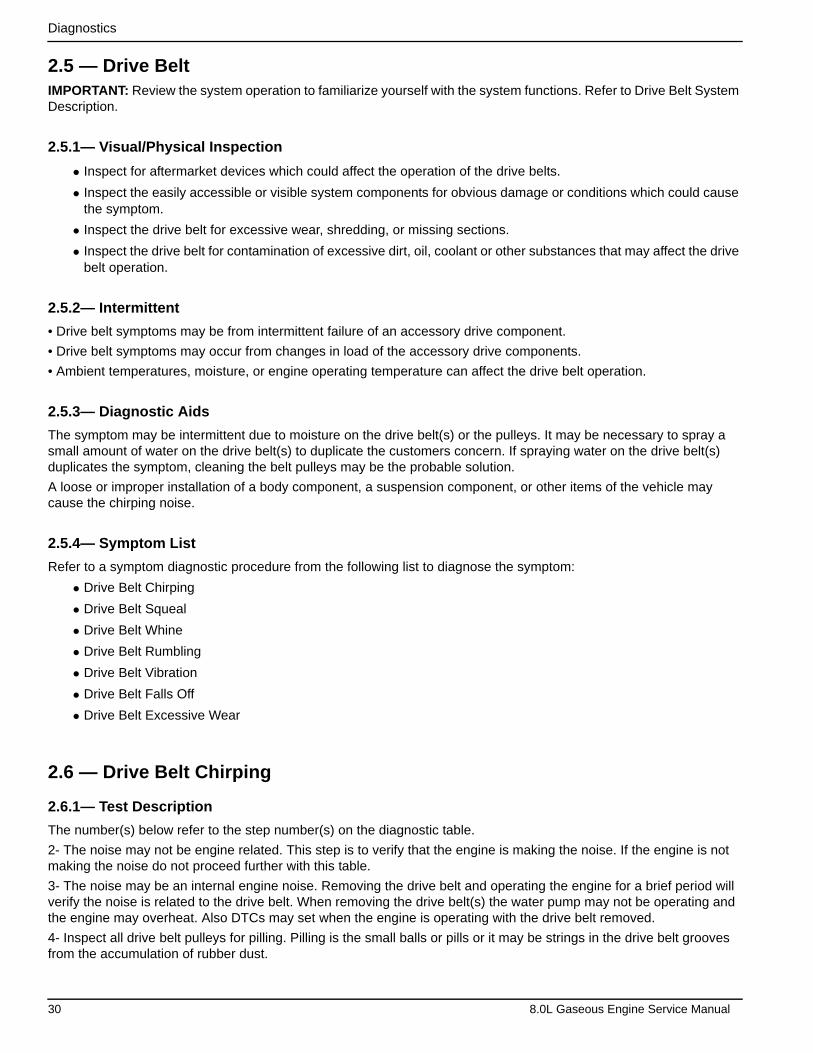
Diagnostics
2.5 — Drive BeltIMPORTANT: Review the system operation to familiarize yourself with the system functions. Refer to Drive Belt System Description.
2.5.1— Visual/Physical Inspection
• Inspect for aftermarket devices which could affect the operation of the drive belts.
• Inspect the easily accessible or visible system components for obvious damage or conditions which could cause the symptom.
• Inspect the drive belt for excessive wear, shredding, or missing sections.
• Inspect the drive belt for contamination of excessive dirt, oil, coolant or other substances that may affect the drive belt operation.
2.5.2— Intermittent
• Drive belt symptoms may be from intermittent failure of an accessory drive component.
• Drive belt symptoms may occur from changes in load of the accessory drive components.
• Ambient temperatures, moisture, or engine operating temperature can affect the drive belt operation.
2.5.3— Diagnostic Aids
The symptom may be intermittent due to moisture on the drive belt(s) or the pulleys. It may be necessary to spray a small amount of water on the drive belt(s) to duplicate the customers concern. If spraying water on the drive belt(s) duplicates the symptom, cleaning the belt pulleys may be the probable solution.
A loose or improper installation of a body component, a suspension component, or other items of the vehicle may cause the chirping noise.
2.5.4— Symptom List
Refer to a symptom diagnostic procedure from the following list to diagnose the symptom:
• Drive Belt Chirping
• Drive Belt Squeal
• Drive Belt Whine
• Drive Belt Rumbling
• Drive Belt Vibration
• Drive Belt Falls Off
• Drive Belt Excessive Wear
2.6 — Drive Belt Chirping
2.6.1— Test Description
The number(s) below refer to the step number(s) on the diagnostic table.
2- The noise may not be engine related. This step is to verify that the engine is making the noise. If the engine is not making the noise do not proceed further with this table.
3- The noise may be an internal engine noise. Removing the drive belt and operating the engine for a brief period will verify the noise is related to the drive belt. When removing the drive belt(s) the water pump may not be operating and the engine may overheat. Also DTCs may set when the engine is operating with the drive belt removed.
4- Inspect all drive belt pulleys for pilling. Pilling is the small balls or pills or it may be strings in the drive belt grooves from the accumulation of rubber dust.
30 8.0L Gaseous Engine Service Manual
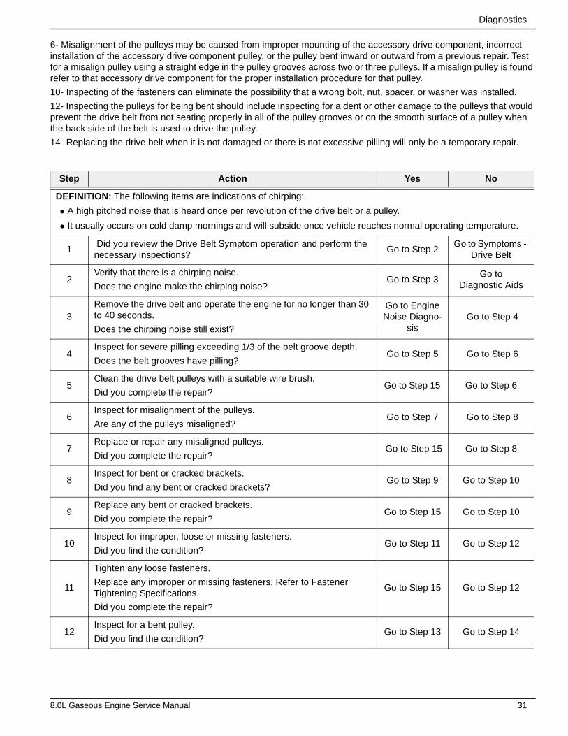
Diagnostics
6- Misalignment of the pulleys may be caused from improper mounting of the accessory drive component, incorrect installation of the accessory drive component pulley, or the pulley bent inward or outward from a previous repair. Test for a misalign pulley using a straight edge in the pulley grooves across two or three pulleys. If a misalign pulley is found refer to that accessory drive component for the proper installation procedure for that pulley.
10- Inspecting of the fasteners can eliminate the possibility that a wrong bolt, nut, spacer, or washer was installed.
12- Inspecting the pulleys for being bent should include inspecting for a dent or other damage to the pulleys that would prevent the drive belt from not seating properly in all of the pulley grooves or on the smooth surface of a pulley when the back side of the belt is used to drive the pulley.
14- Replacing the drive belt when it is not damaged or there is not excessive pilling will only be a temporary repair.
Step Action Yes No
DEFINITION: The following items are indications of chirping:
• A high pitched noise that is heard once per revolution of the drive belt or a pulley.
• It usually occurs on cold damp mornings and will subside once vehicle reaches normal operating temperature.
1 Did you review the Drive Belt Symptom operation and perform the necessary inspections?
Go to Step 2Go to Symptoms -
Drive Belt
2Verify that there is a chirping noise.
Does the engine make the chirping noise?Go to Step 3
Go to Diagnostic Aids
3Remove the drive belt and operate the engine for no longer than 30 to 40 seconds.
Does the chirping noise still exist?
Go to Engine Noise Diagno-
sis Go to Step 4
4Inspect for severe pilling exceeding 1/3 of the belt groove depth.
Does the belt grooves have pilling?Go to Step 5 Go to Step 6
5Clean the drive belt pulleys with a suitable wire brush.
Did you complete the repair?Go to Step 15 Go to Step 6
6Inspect for misalignment of the pulleys.
Are any of the pulleys misaligned?Go to Step 7 Go to Step 8
7Replace or repair any misaligned pulleys.
Did you complete the repair? Go to Step 15 Go to Step 8
8Inspect for bent or cracked brackets.
Did you find any bent or cracked brackets?Go to Step 9 Go to Step 10
9Replace any bent or cracked brackets.
Did you complete the repair?Go to Step 15 Go to Step 10
10Inspect for improper, loose or missing fasteners.
Did you find the condition?Go to Step 11 Go to Step 12
11
Tighten any loose fasteners.
Replace any improper or missing fasteners. Refer to Fastener Tightening Specifications.
Did you complete the repair?
Go to Step 15 Go to Step 12
12Inspect for a bent pulley.
Did you find the condition?Go to Step 13 Go to Step 14
8.0L Gaseous Engine Service Manual 31
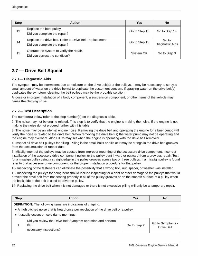
Diagnostics
2.7 — Drive Belt Squeal
2.7.1— Diagnostic Aids
The symptom may be intermittent due to moisture on the drive belt(s) or the pulleys. It may be necessary to spray a small amount of water on the drive belt(s) to duplicate the customers concern. If spraying water on the drive belt(s) duplicates the symptom, cleaning the belt pulleys may be the probable solution.
A loose or improper installation of a body component, a suspension component, or other items of the vehicle may cause the chirping noise.
2.7.2— Test Description
The number(s) below refer to the step number(s) on the diagnostic table.
2- The noise may not be engine related. This step is to verify that the engine is making the noise. If the engine is not making the noise do not proceed further with this table.
3- The noise may be an internal engine noise. Removing the drive belt and operating the engine for a brief period will verify the noise is related to the drive belt. When removing the drive belt(s) the water pump may not be operating and the engine may overheat. Also DTCs may set when the engine is operating with the drive belt removed.
4- Inspect all drive belt pulleys for pilling. Pilling is the small balls or pills or it may be strings in the drive belt grooves from the accumulation of rubber dust.
6- Misalignment of the pulleys may be caused from improper mounting of the accessory drive component, incorrect installation of the accessory drive component pulley, or the pulley bent inward or outward from a previous repair. Test for a misalign pulley using a straight edge in the pulley grooves across two or three pulleys. If a misalign pulley is found refer to that accessory drive component for the proper installation procedure for that pulley.
10- Inspecting of the fasteners can eliminate the possibility that a wrong bolt, nut, spacer, or washer was installed.
12- Inspecting the pulleys for being bent should include inspecting for a dent or other damage to the pulleys that would prevent the drive belt from not seating properly in all of the pulley grooves or on the smooth surface of a pulley when the back side of the belt is used to drive the pulley.
14- Replacing the drive belt when it is not damaged or there is not excessive pilling will only be a temporary repair.
Step Action Yes No
13Replace the bent pulley.
Did you complete the repair?Go to Step 15 Go to Step 14
14Replace the drive belt. Refer to Drive Belt Replacement.
Did you complete the repair?Go to Step 15
Go toDiagnostic Aids
15Operate the system to verify the repair.
Did you correct the condition?System OK Go to Step 3
Step Action Yes No
DEFINITION: The following items are indications of chirping:
• A high pitched noise that is heard once per revolution of the drive belt or a pulley.
• It usually occurs on cold damp mornings.
1Did you review the Drive Belt Symptom operation and perform the
necessary inspections?Go to Step 2
Go to Symptoms - Drive Belt
32 8.0L Gaseous Engine Service Manual
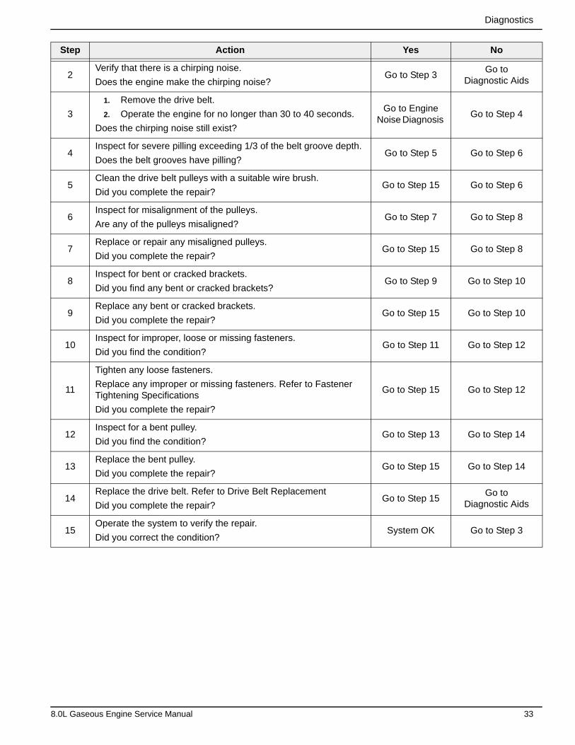
Diagnostics
2Verify that there is a chirping noise.
Does the engine make the chirping noise?Go to Step 3
Go to Diagnostic Aids
3
1. Remove the drive belt.
2. Operate the engine for no longer than 30 to 40 seconds.
Does the chirping noise still exist?
Go to Engine Noise Diagnosis
Go to Step 4
4Inspect for severe pilling exceeding 1/3 of the belt groove depth.
Does the belt grooves have pilling?Go to Step 5 Go to Step 6
5Clean the drive belt pulleys with a suitable wire brush.
Did you complete the repair?Go to Step 15 Go to Step 6
6Inspect for misalignment of the pulleys.
Are any of the pulleys misaligned?Go to Step 7 Go to Step 8
7Replace or repair any misaligned pulleys.
Did you complete the repair?Go to Step 15 Go to Step 8
8Inspect for bent or cracked brackets.
Did you find any bent or cracked brackets?Go to Step 9 Go to Step 10
9Replace any bent or cracked brackets.
Did you complete the repair?Go to Step 15 Go to Step 10
10Inspect for improper, loose or missing fasteners.
Did you find the condition?Go to Step 11 Go to Step 12
11
Tighten any loose fasteners.
Replace any improper or missing fasteners. Refer to Fastener Tightening Specifications
Did you complete the repair?
Go to Step 15 Go to Step 12
12Inspect for a bent pulley.
Did you find the condition?Go to Step 13 Go to Step 14
13Replace the bent pulley.
Did you complete the repair?Go to Step 15 Go to Step 14
14Replace the drive belt. Refer to Drive Belt Replacement
Did you complete the repair?Go to Step 15
Go to Diagnostic Aids
15Operate the system to verify the repair.
Did you correct the condition?System OK Go to Step 3
Step Action Yes No
8.0L Gaseous Engine Service Manual 33
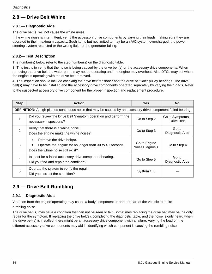
Diagnostics
2.8 — Drive Belt Whine
2.8.1— Diagnostic Aids
The drive belt(s) will not cause the whine noise.
If the whine noise is intermittent, verify the accessory drive components by varying their loads making sure they are operated to their maximum capacity. Such items but not limited to may be an A/C system overcharged, the power steering system restricted or the wrong fluid, or the generator failing.
2.8.2— Test Description
The number(s) below refer to the step number(s) on the diagnostic table.
3- This test is to verify that the noise is being caused by the drive belt(s) or the accessory drive components. When removing the drive belt the water pump may not be operating and the engine may overheat. Also DTCs may set when the engine is operating with the drive belt removed.
4- The inspection should include checking the drive belt tensioner and the drive belt idler pulley bearings. The drive belt(s) may have to be installed and the accessory drive components operated separately by varying their loads. Refer
to the suspected accessory drive component for the proper inspection and replacement procedure.
2.9 — Drive Belt Rumbling
2.9.1— Diagnostic Aids
Vibration from the engine operating may cause a body component or another part of the vehicle to make
rumbling noise.
The drive belt(s) may have a condition that can not be seen or felt. Sometimes replacing the drive belt may be the only repair for the symptom. If replacing the drive belt(s), completing the diagnostic table, and the noise is only heard when the drive belt(s) is installed, there might be an accessory drive component with a failure. Varying the load on the
different accessory drive components may aid in identifying which component is causing the rumbling noise.
Step Action Yes No
DEFINITION: A high pitched continuous noise that may be caused by an accessory drive component failed bearing.
1Did you review the Drive Belt Symptom operation and perform the
necessary inspections?Go to Step 2
Go to Symptoms - Drive Belt
2Verify that there is a whine noise.
Does the engine make the whine noise?Go to Step 3
Go to Diagnostic Aids
3
1. Remove the drive belt(s).
2. Operate the engine for no longer than 30 to 40 seconds.
Does the whine noise still exist?
Go to Engine Noise Diagnosis
Go to Step 4
4Inspect for a failed accessory drive component bearing.
Did you find and repair the condition?Go to Step 5
Go to Diagnostic Aids
5Operate the system to verify the repair.
Did you correct the condition?System OK —
34 8.0L Gaseous Engine Service Manual

Diagnostics
2.9.2— Test Description
The number(s) below refer to the step number(s) on the diagnostic table.
2- This test is to verify that the symptom is present during diagnosing. Other vehicle components may cause a similar symptom.
3- This test is to verify that the drive belt(s) is causing the rumbling noise. Rumbling noise may be confused with an internal engine noise due to the similarity in the description. Remove only one drive belt at a time if the vehicle has
multiple drive belts. When removing the drive belt the water pump may not be operating and the engine may overheat. Also, faults may set when the engine is operating with the drive belt removed.
4- Inspecting the drive belt(s) is to ensure that it is not causing a the noise. Small cracks across the ribs of the drive belt will not cause the noise. Belt separation is identified by the plys of the belt separating and may be seen at the edge of the belt our felt as a lump in the belt.
5- Small amounts of pilling is normal condition and acceptable. When the pilling is severe the drive belt does not have a smooth surface for proper operation.
Step Action Yes No
DEFINITION:
• A low pitch tapping, knocking, or thumping noise heard at or just above idle.
• Heard once per revolution of the drive belt or a pulley.
• Rumbling may be caused from:
– Pilling, the accumulation of rubber dust that forms small balls (pills) or strings in the drive belt pulley groove
– The separation of the drive belt
– A damaged drive belt
1Did you review the Drive Belt Symptom operation and perform the necessary inspections?
Go to Step 2Go to Symptoms -
Drive Belt
2Verify that there is a rumbling noise.
Does the engine make the rumbling noise?Go to Step 3
Go toDiagnostic Aids
3
1. Remove the drive belt(s).
2. Operate the engine for no longer than 30 to 40 seconds.
Does the rumbling noise still exist?
Go to Engine Noise Diagnosis
Go to Step 4
4Inspect the drive belt(s) for damage, separation, or sections of missing ribs.
Did you find any of these conditions?Go to Step 7 Go to Step 5
5Inspect for severe pilling of more than 1/3 of the drive belt pulley grooves.
Did you find severe pilling?Go to Step 6 Go to Step 7
6
1. Clean the drive belt pulleys using a suitable wire brush.
2. Reinstall the drive belt. Refer to Drive Belt Replacement.
Did you complete the repair?
Go to Step 8 Go to Step 7
7Install a new drive belt. Refer to Drive Belt Replacement.
Did you complete the replacement?Go to Step 8 —
8Operate the system to verify the repair.
Did you correct the condition?System OK
Go to Diagnostic Aids
8.0L Gaseous Engine Service Manual 35
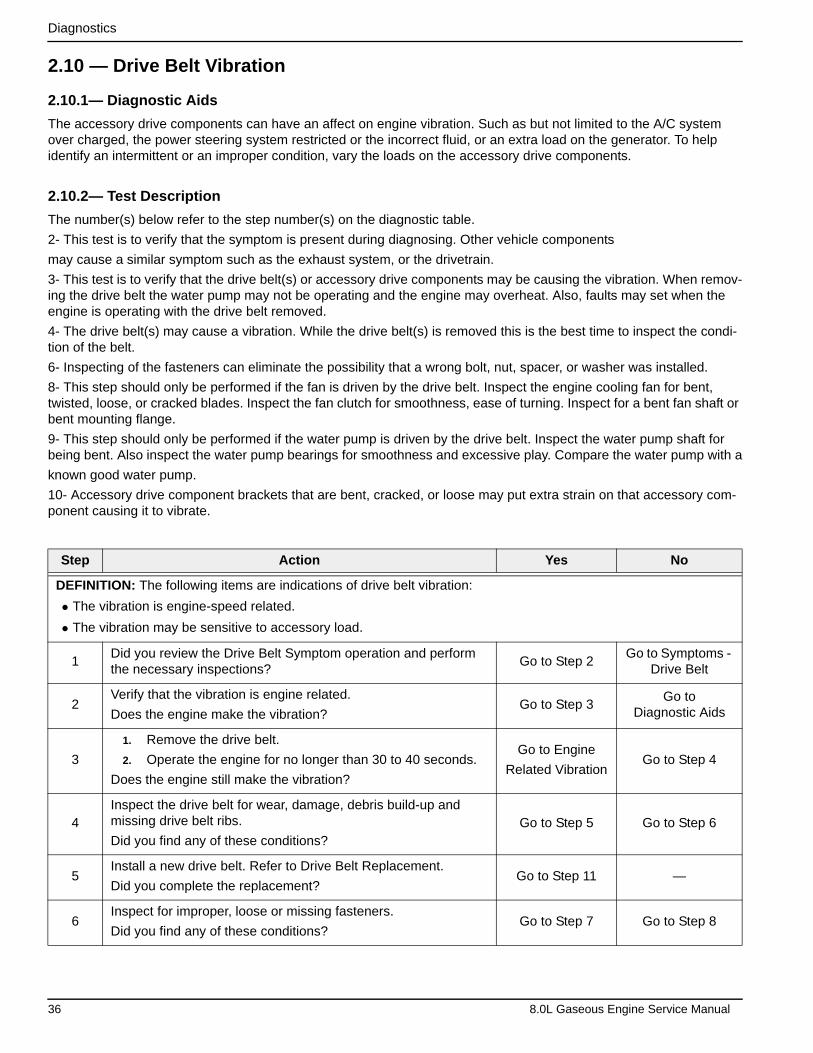
Diagnostics
2.10 — Drive Belt Vibration
2.10.1— Diagnostic Aids
The accessory drive components can have an affect on engine vibration. Such as but not limited to the A/C system over charged, the power steering system restricted or the incorrect fluid, or an extra load on the generator. To help identify an intermittent or an improper condition, vary the loads on the accessory drive components.
2.10.2— Test Description
The number(s) below refer to the step number(s) on the diagnostic table.
2- This test is to verify that the symptom is present during diagnosing. Other vehicle components
may cause a similar symptom such as the exhaust system, or the drivetrain.
3- This test is to verify that the drive belt(s) or accessory drive components may be causing the vibration. When remov-ing the drive belt the water pump may not be operating and the engine may overheat. Also, faults may set when the engine is operating with the drive belt removed.
4- The drive belt(s) may cause a vibration. While the drive belt(s) is removed this is the best time to inspect the condi-tion of the belt.
6- Inspecting of the fasteners can eliminate the possibility that a wrong bolt, nut, spacer, or washer was installed.
8- This step should only be performed if the fan is driven by the drive belt. Inspect the engine cooling fan for bent, twisted, loose, or cracked blades. Inspect the fan clutch for smoothness, ease of turning. Inspect for a bent fan shaft or bent mounting flange.
9- This step should only be performed if the water pump is driven by the drive belt. Inspect the water pump shaft for being bent. Also inspect the water pump bearings for smoothness and excessive play. Compare the water pump with a
known good water pump.
10- Accessory drive component brackets that are bent, cracked, or loose may put extra strain on that accessory com-ponent causing it to vibrate.
Step Action Yes No
DEFINITION: The following items are indications of drive belt vibration:
• The vibration is engine-speed related.
• The vibration may be sensitive to accessory load.
1Did you review the Drive Belt Symptom operation and perform the necessary inspections?
Go to Step 2Go to Symptoms -
Drive Belt
2Verify that the vibration is engine related.
Does the engine make the vibration?Go to Step 3
Go to Diagnostic Aids
3
1. Remove the drive belt.
2. Operate the engine for no longer than 30 to 40 seconds.
Does the engine still make the vibration?
Go to Engine
Related VibrationGo to Step 4
4Inspect the drive belt for wear, damage, debris build-up and missing drive belt ribs.
Did you find any of these conditions?Go to Step 5 Go to Step 6
5Install a new drive belt. Refer to Drive Belt Replacement.
Did you complete the replacement?Go to Step 11 —
6Inspect for improper, loose or missing fasteners.
Did you find any of these conditions?Go to Step 7 Go to Step 8
36 8.0L Gaseous Engine Service Manual

Diagnostics
2.11 — Drive Belt Falls Off
2.11.1— Diagnostic Aids
If the drive belt(s) repeatedly falls off the drive belt pulleys, this is because of pulley misalignment.
An extra load that is quickly applied or released by an accessory drive component may cause the drive belt to fall off the pulleys. Verify the accessory drive components operate properly.
If the drive belt(s) is the incorrect length, the drive belt tensioner may not keep the proper tension on the drive belt.
2.11.2— Test Description
The number(s) below refer to the step number(s) on the diagnostic table.
2- This inspection is to verify the condition of the drive belt. Damage may of occurred to the drive belt when the drive belt fell off. The drive belt may of been damaged, which caused the drive belt to fall off. Inspect the belt for cuts, tears, sections of ribs missing, or damaged belt plys.
4- Misalignment of the pulleys may be caused from improper mounting of the accessory drive component, incorrect installation of the accessory drive component pulley, or the pulley bent inward or outward from a previous repair. Test for a misalign pulley using a straight edge in the pulley grooves across two or three pulleys. If a misalign pulley is found refer to that accessory drive component for the proper installation procedure of that pulley.
5- Inspecting the pulleys for being bent should include inspecting for a dent or other damage to the pulleys that would prevent the drive belt from not seating properly in all of the pulley grooves or on the smooth surface of a pulley when
the back side of the belt is used to drive the pulley.
6- Accessory drive component brackets that are bent or cracked will let the drive belt fall off.
7- Inspecting of the fasteners can eliminate the possibility that a wrong bolt, nut, spacer, or washer was installed. Miss-ing. loose, or the wrong fasteners may cause pulley misalignment from the bracket moving under load. Over tightening of the fasteners may cause misalignment of the accessory component bracket.
7
Tighten any loose fasteners.
Replace improper or missing fasteners. Refer to Fastener Tight-ening Specifications.
Did you complete the repair?
Go to Step 11 —
8Inspect for damaged fan blades or bent fan clutch shaft, if the fan is belt driven. Refer to Fan Replacement.
Did you find and correct the condition? Go to Step 11 Go to Step 9
9Inspect for a bent water pump shaft, if the water pump is belt driven. Refer to Water Pump Replacement.
Did you find and correct the condition?Go to Step 11 Go to Step 10
10Inspect for bent or cracked brackets.
Did you find and correct the condition?Go to Step 11
Go toDiagnostic Aids
11Operate the system to verify the repair.
Did you correct the condition?System OK Go to Step 3
Step Action Yes No
8.0L Gaseous Engine Service Manual 37
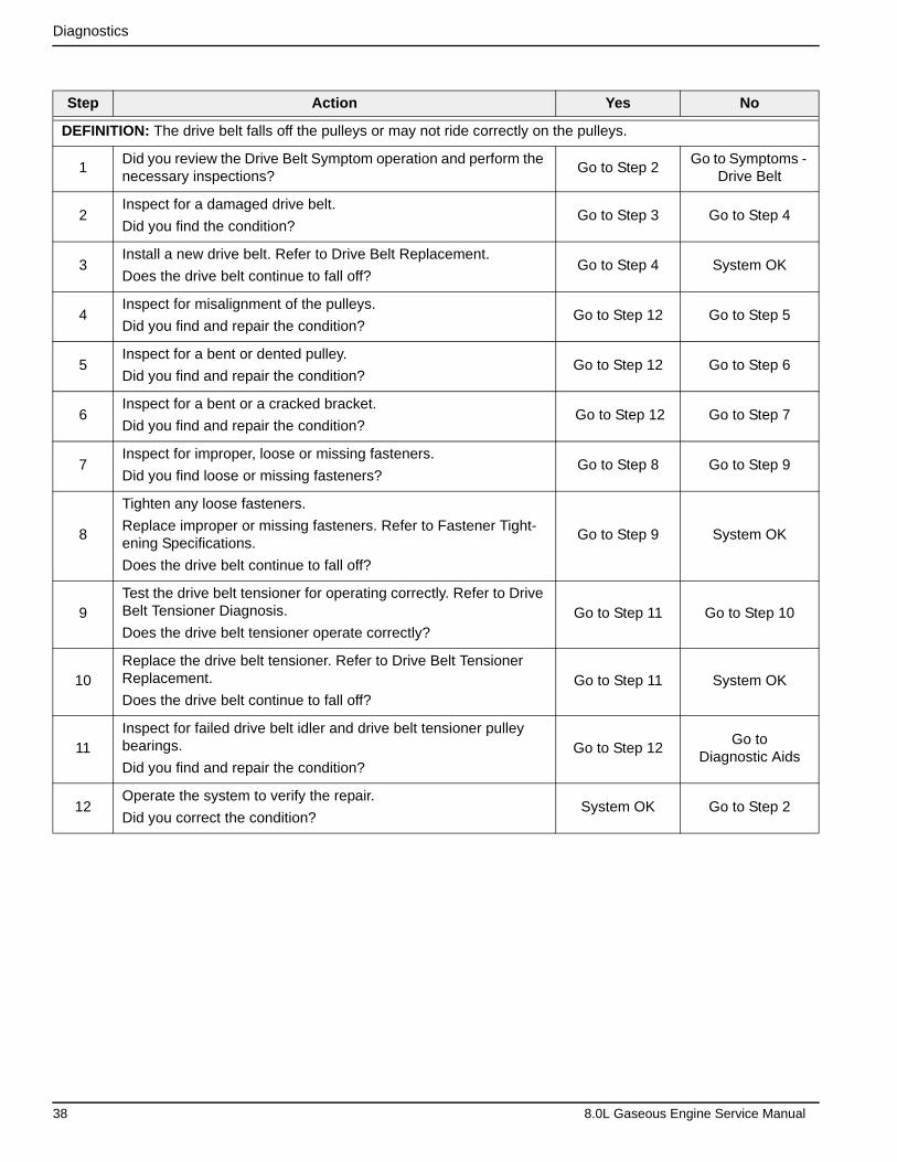
Diagnostics
Step Action Yes No
DEFINITION: The drive belt falls off the pulleys or may not ride correctly on the pulleys.
1Did you review the Drive Belt Symptom operation and perform the necessary inspections?
Go to Step 2Go to Symptoms -
Drive Belt
2Inspect for a damaged drive belt.
Did you find the condition?Go to Step 3 Go to Step 4
3Install a new drive belt. Refer to Drive Belt Replacement.
Does the drive belt continue to fall off?Go to Step 4 System OK
4Inspect for misalignment of the pulleys.
Did you find and repair the condition?Go to Step 12 Go to Step 5
5Inspect for a bent or dented pulley.
Did you find and repair the condition?Go to Step 12 Go to Step 6
6Inspect for a bent or a cracked bracket.
Did you find and repair the condition? Go to Step 12 Go to Step 7
7Inspect for improper, loose or missing fasteners.
Did you find loose or missing fasteners?Go to Step 8 Go to Step 9
8
Tighten any loose fasteners.
Replace improper or missing fasteners. Refer to Fastener Tight-ening Specifications.
Does the drive belt continue to fall off?
Go to Step 9 System OK
9Test the drive belt tensioner for operating correctly. Refer to Drive Belt Tensioner Diagnosis.
Does the drive belt tensioner operate correctly?Go to Step 11 Go to Step 10
10Replace the drive belt tensioner. Refer to Drive Belt Tensioner Replacement.
Does the drive belt continue to fall off?Go to Step 11 System OK
11Inspect for failed drive belt idler and drive belt tensioner pulley bearings.
Did you find and repair the condition?Go to Step 12
Go to Diagnostic Aids
12Operate the system to verify the repair.
Did you correct the condition?System OK Go to Step 2
38 8.0L Gaseous Engine Service Manual
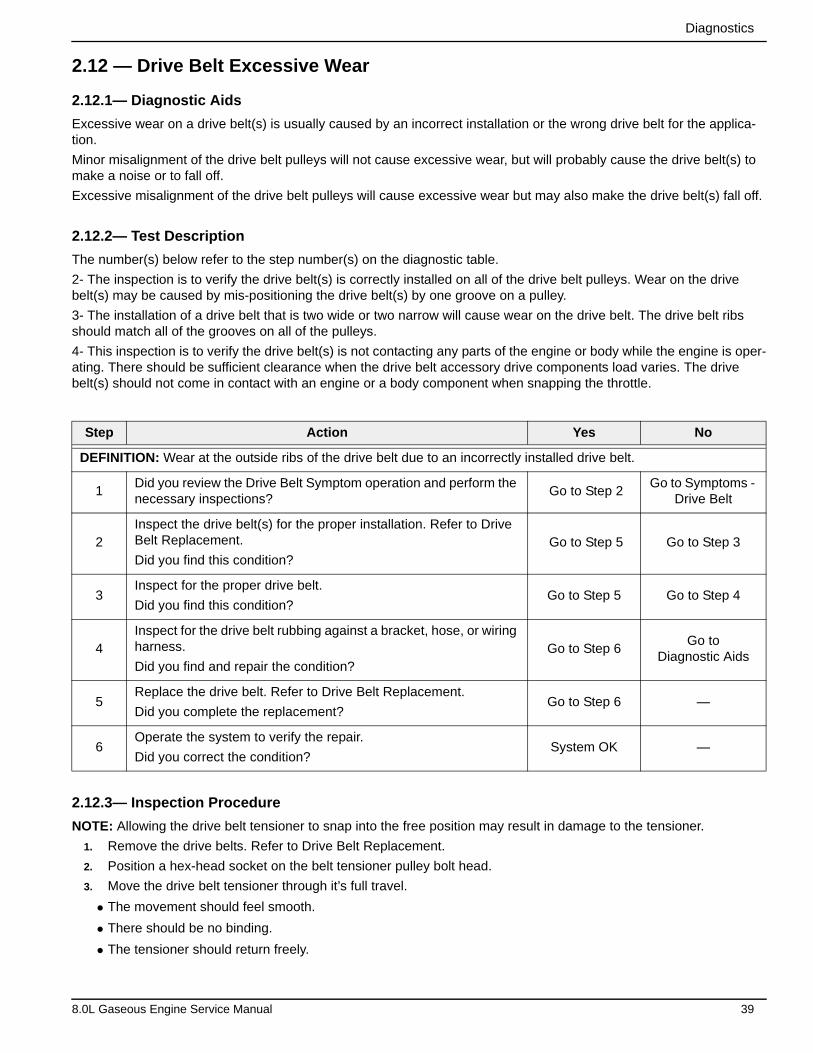
Diagnostics
2.12 — Drive Belt Excessive Wear
2.12.1— Diagnostic Aids
Excessive wear on a drive belt(s) is usually caused by an incorrect installation or the wrong drive belt for the applica-tion.
Minor misalignment of the drive belt pulleys will not cause excessive wear, but will probably cause the drive belt(s) to make a noise or to fall off.
Excessive misalignment of the drive belt pulleys will cause excessive wear but may also make the drive belt(s) fall off.
2.12.2— Test Description
The number(s) below refer to the step number(s) on the diagnostic table.
2- The inspection is to verify the drive belt(s) is correctly installed on all of the drive belt pulleys. Wear on the drive belt(s) may be caused by mis-positioning the drive belt(s) by one groove on a pulley.
3- The installation of a drive belt that is two wide or two narrow will cause wear on the drive belt. The drive belt ribs should match all of the grooves on all of the pulleys.
4- This inspection is to verify the drive belt(s) is not contacting any parts of the engine or body while the engine is oper-ating. There should be sufficient clearance when the drive belt accessory drive components load varies. The drive belt(s) should not come in contact with an engine or a body component when snapping the throttle.
2.12.3— Inspection Procedure
NOTE: Allowing the drive belt tensioner to snap into the free position may result in damage to the tensioner.
1. Remove the drive belts. Refer to Drive Belt Replacement.
2. Position a hex-head socket on the belt tensioner pulley bolt head.
3. Move the drive belt tensioner through it’s full travel.
• The movement should feel smooth.
• There should be no binding.
• The tensioner should return freely.
Step Action Yes No
DEFINITION: Wear at the outside ribs of the drive belt due to an incorrectly installed drive belt.
1Did you review the Drive Belt Symptom operation and perform the necessary inspections?
Go to Step 2Go to Symptoms -
Drive Belt
2Inspect the drive belt(s) for the proper installation. Refer to Drive Belt Replacement.
Did you find this condition? Go to Step 5 Go to Step 3
3Inspect for the proper drive belt.
Did you find this condition?Go to Step 5 Go to Step 4
4Inspect for the drive belt rubbing against a bracket, hose, or wiring harness.
Did you find and repair the condition?Go to Step 6
Go toDiagnostic Aids
5Replace the drive belt. Refer to Drive Belt Replacement.
Did you complete the replacement?Go to Step 6 —
6Operate the system to verify the repair.
Did you correct the condition?System OK —
8.0L Gaseous Engine Service Manual 39
Diagnostics
4. If any binding is observed, replace the tensioner. Refer to Drive Belt Tensioner Replacement.
5. Install the drive belt. Refer to Drive Belt Replacement.
1. Disconnect the ignition coil wire harness connector at the front of the engine on the left cylinder bank and at the rear of the engine at the right cylinder bank.
2. Disconnect the fuel injector electrical harness connector at the rear of the intake manifold.
3. Remove all the spark plugs.
4. Block the throttle plate wide open.
5. Charge the battery if the battery is not fully charged.
6. Start with the compression gauge at zero. Then crank the engine through four compression strokes (four puffs).
7. Make the compression check the same for each cylinder. Record the reading.
The minimum compression in any one cylinder should not be less than 70 percent of the highest cylinder. No cyl-inder should read less than 690 kPa (100 psi). For example, if the highest pressure in any one cylinder is 1035 kPa (150 psi), the lowest allowable pressure for any other cylinder would be 725 kPa (105 psi). (1035 x 70% = 725) (150 x 70% = 105).
8. If some cylinders have low compression, inject approximately 15 ml (one tablespoon) of engine oil into the com-bustion chamber through the spark plug hole.
• Normal — Compression builds up quickly and evenly to the specified compression for each cylinder.
• Piston Rings Leaking — Compression is low on the first stroke. Then compression builds up with the following strokes but does not reach normal. Compression improves considerably when you add oil.
• Valves Leaking — Compression is low on the first stroke. Compression usually does not build up on the following strokes. Compression does not improve much when you add oil.
• If two adjacent cylinders have lower than normal compression, and injecting oil into the cylinders does not increase the compression, the cause may be a head gasket leaking between the two cylinders.
40 8.0L Gaseous Engine Service Manual
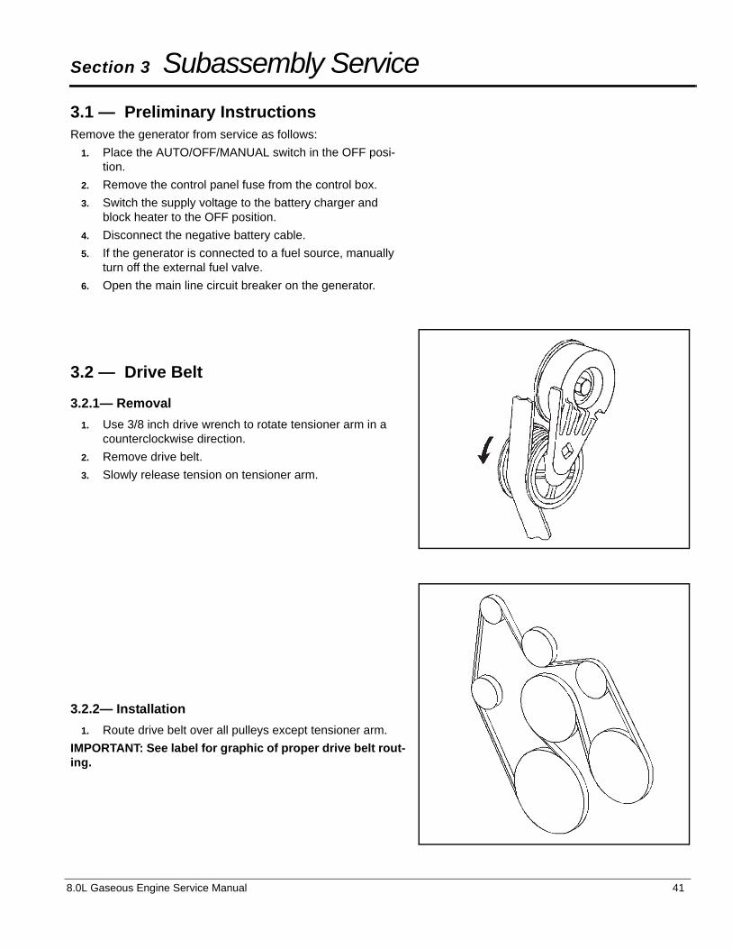
Section 3 Subassembly Service
3.1 — Preliminary InstructionsRemove the generator from service as follows:
1. Place the AUTO/OFF/MANUAL switch in the OFF posi-tion.
2. Remove the control panel fuse from the control box.
3. Switch the supply voltage to the battery charger and block heater to the OFF position.
4. Disconnect the negative battery cable.
5. If the generator is connected to a fuel source, manually turn off the external fuel valve.
6. Open the main line circuit breaker on the generator.
3.2 — Drive Belt
3.2.1— Removal
1. Use 3/8 inch drive wrench to rotate tensioner arm in a counterclockwise direction.
2. Remove drive belt.
3. Slowly release tension on tensioner arm.
3.2.2— Installation
1. Route drive belt over all pulleys except tensioner arm.
IMPORTANT: See label for graphic of proper drive belt rout-ing.
8.0L Gaseous Engine Service Manual 41
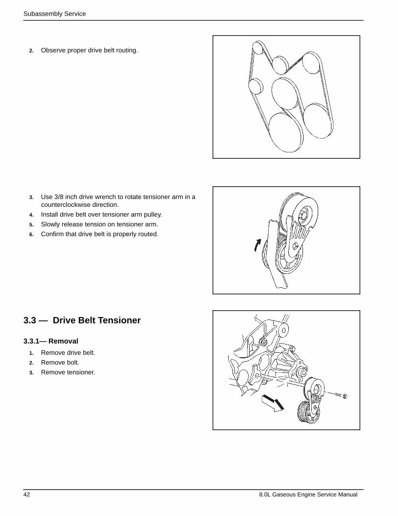
Subassembly Service
2. Observe proper drive belt routing.
3. Use 3/8 inch drive wrench to rotate tensioner arm in a counterclockwise direction.
4. Install drive belt over tensioner arm pulley.
5. Slowly release tension on tensioner arm.
6. Confirm that drive belt is properly routed.
3.3 — Drive Belt Tensioner
3.3.1— Removal
1. Remove drive belt.
2. Remove bolt.
3. Remove tensioner.
42 8.0L Gaseous Engine Service Manual

Subassembly Service
3.3.2— Installation
1. Install drive belt tensioner assembly.
2. Install tensioner assembly bolt.
3. Tighten tensioner assembly bolt to 37 ft-lbs (50 N-m).
4. Install drive belt.
3.4 — Idler Pulley
3.4.1— Removal
1. Remove drive belt.
2. Remove drive belt idler pulley from engine.
3.4.2— Installation
1. Install drive belt idler pulley to engine.
2. Tighten bolt to 37 ft-lbs (50 N-m).
3. Install drive belt.
8.0L Gaseous Engine Service Manual 43

Subassembly Service
3.5 — Accessory Mounting Bracket
3.5.1— Removal
1. Remove engine cooling fan.
2. Remove drive belt.
3. Remove three bolts and nut to release accessory mount-ing bracket from engine.
44 8.0L Gaseous Engine Service Manual

Subassembly Service
3.5.2— Installation
1. Slide bracket on stud.
2. Install three bolts and nut.
3. Tighten bolts and nut to 32 ft-lbs (44 N-m).
4. Install drive belt.
5. Install engine cooling fan.
8.0L Gaseous Engine Service Manual 45
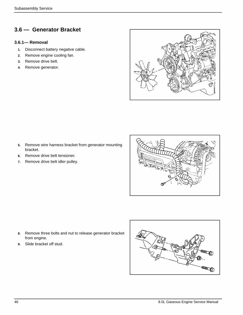
Subassembly Service
3.6 — Generator Bracket
3.6.1— Removal
1. Disconnect battery negative cable.
2. Remove engine cooling fan.
3. Remove drive belt.
4. Remove generator.
5. Remove wire harness bracket from generator mounting bracket.
6. Remove drive belt tensioner.
7. Remove drive belt idler pulley.
8. Remove three bolts and nut to release generator bracket from engine.
9. Slide bracket off stud.
46 8.0L Gaseous Engine Service Manual
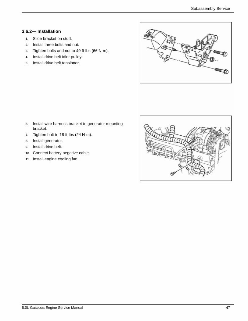
Subassembly Service
3.6.2— Installation
1. Slide bracket on stud.
2. Install three bolts and nut.
3. Tighten bolts and nut to 49 ft-lbs (66 N-m).
4. Install drive belt idler pulley.
5. Install drive belt tensioner.
6. Install wire harness bracket to generator mounting bracket.
7. Tighten bolt to 18 ft-lbs (24 N-m).
8. Install generator.
9. Install drive belt.
10. Connect battery negative cable.
11. Install engine cooling fan.
8.0L Gaseous Engine Service Manual 47
Subassembly Service
3.7 — Distributor
3.7.1— Removal
1. Remove fan shrouding as necessary to access crankshaft harmonic balancer.
2. Disconnect electrical connector from distributor.
3. Loosen four screw hooks and remove distributor cap.
NOTE: Do not remove spark plug wires from distributor cap.
4. Attach ¾ inch socket with ratchet to center bolt of crankshaft harmonic balancer and rotate clockwise (CW) until the following conditions occur:
a) Embossed line on balancer is aligned with timing pointer. See A of Figure 3-1.
b) Rotor points to spark plug wire tower one on the distributor cap. See B of Figure 3-1.
NOTE: The engine is now at Top Dead Center (TDC).
5. Using a paint marker, place four marks as follows:
a) Start 1st paint mark on distributor housing and carry it over onto the intake manifold. See C of Figure 3-1.
b) Place 2nd paint mark on the distributor housing, so that it aligns with the rotor pointer. See D of Figure 3-1.
c) Place 3rd paint mark on a fixed surface of the intake manifold or engine block, so that it aligns with the 2nd paint mark placed on the distributor housing. Use a straight edge for best results. See E of Figure 3-1.
d) Install the distributor cap and place the 4th paint mark on the distributor cap, so that it aligns with the 2nd paint mark on the distributor housing. See E of Figure 3-1.
6. Remove the tamper evident screw cover. Use a small prying tool for best results. See F of Figure 3-1.
NOTE: Discard the screw cover as it will be damaged during removal.
7. Remove the hex screw, flat washer, the bottom of the tamper evident screw cover, and distributor clamp bracket. Discard the screw cover bottom. See G of Figure 3-1.
8. Remove the distributor from the engine, and place the final and 5th paint mark on the distributor housing indicat-ing where the rotor moved. See H of Figure 3-1.
9. Remove and discard the distributor gasket.
3.7.2— Assembly
1. Remove the distributor cap from the new distributor and use a paint marker to transfer the 1st, 2nd and 5th paint marks on the old distributor to the same locations on the new distributor. Also, use the marker to transfer the 4th paint mark on the old distributor cap to the same location on the new distributor cap.
2. Install new gasket on the distributor shaft. See A of Figure 3-2.
3. Install the distributor in the engine and align paint marks 1-4.
NOTE: If the paint marks do not line up, remove the distributor and align the distributor notch with the oil pump drive gear slot. Repeat step 3.
48 8.0L Gaseous Engine Service Manual
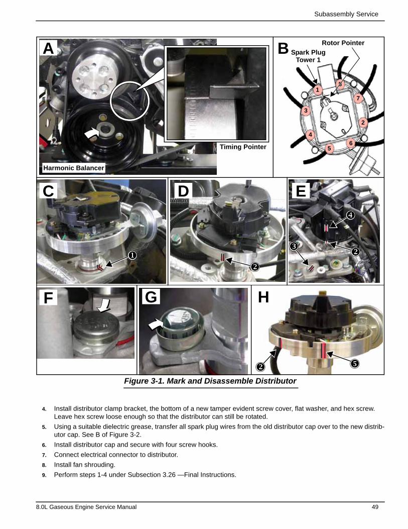
Subassembly Service
Figure 3-1. Mark and Disassemble Distributor
4. Install distributor clamp bracket, the bottom of a new tamper evident screw cover, flat washer, and hex screw. Leave hex screw loose enough so that the distributor can still be rotated.
5. Using a suitable dielectric grease, transfer all spark plug wires from the old distributor cap over to the new distrib-utor cap. See B of Figure 3-2.
6. Install distributor cap and secure with four screw hooks.
7. Connect electrical connector to distributor.
8. Install fan shrouding.
9. Perform steps 1-4 under Subsection 3.26 —Final Instructions.
A B Spark Plug
Rotor Pointer
Tower 1
Timing Pointer
Harmonic Balancer
C D E
F
G
8
7
65
4
3
2
1
H
8.0L Gaseous Engine Service Manual 49
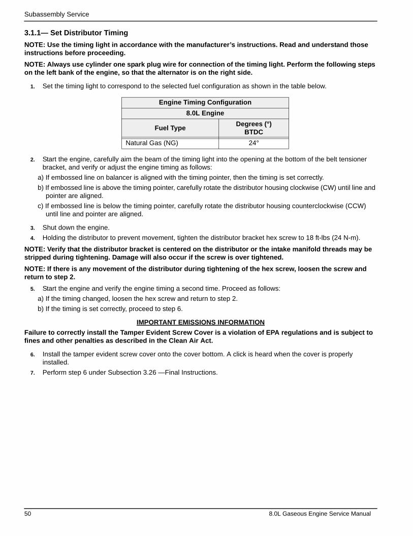
Subassembly Service
3.1.1— Set Distributor Timing
NOTE: Use the timing light in accordance with the manufacturer’s instructions. Read and understand those instructions before proceeding.
NOTE: Always use cylinder one spark plug wire for connection of the timing light. Perform the following steps on the left bank of the engine, so that the alternator is on the right side.
1. Set the timing light to correspond to the selected fuel configuration as shown in the table below.
2. Start the engine, carefully aim the beam of the timing light into the opening at the bottom of the belt tensioner bracket, and verify or adjust the engine timing as follows:
a) If embossed line on balancer is aligned with the timing pointer, then the timing is set correctly.
b) If embossed line is above the timing pointer, carefully rotate the distributor housing clockwise (CW) until line and pointer are aligned.
c) If embossed line is below the timing pointer, carefully rotate the distributor housing counterclockwise (CCW) until line and pointer are aligned.
3. Shut down the engine.
4. Holding the distributor to prevent movement, tighten the distributor bracket hex screw to 18 ft-lbs (24 N-m).
NOTE: Verify that the distributor bracket is centered on the distributor or the intake manifold threads may be stripped during tightening. Damage will also occur if the screw is over tightened.
NOTE: If there is any movement of the distributor during tightening of the hex screw, loosen the screw and return to step 2.
5. Start the engine and verify the engine timing a second time. Proceed as follows:
a) If the timing changed, loosen the hex screw and return to step 2.
b) If the timing is set correctly, proceed to step 6.
IMPORTANT EMISSIONS INFORMATION
Failure to correctly install the Tamper Evident Screw Cover is a violation of EPA regulations and is subject to fines and other penalties as described in the Clean Air Act.
6. Install the tamper evident screw cover onto the cover bottom. A click is heard when the cover is properly installed.
7. Perform step 6 under Subsection 3.26 —Final Instructions.
Engine Timing Configuration
8.0L Engine
Fuel TypeDegrees (°)
BTDC
Natural Gas (NG) 24°
50 8.0L Gaseous Engine Service Manual

Subassembly Service
Figure 3-2. Assemble Distributor and Install Spark Plug Wires
1
3
5
7
2
4
6
8
8
64
2
7
5
3
1
5
2
6
4
3
8
7
Item Description
1 Distributor
2 Gasket
3 Rotor
4 Distributor Clamp Bracket
5 Tamper Evident Screw Cover
6 Flat Washer
7 Hex Screw
8 Distributor Cap
9 Spark Plug Wires
1
5
9
B
A
Spark Plug Wire LocationsDistributor Assembly
8.0L Gaseous Engine Service Manual 51
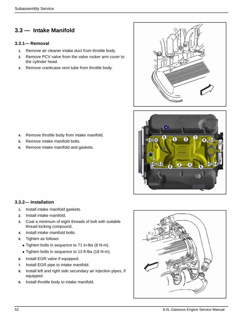
Subassembly Service
3.3 — Intake Manifold
3.3.1— Removal
1. Remove air cleaner intake duct from throttle body.
2. Remove PCV valve from the valve rocker arm cover to the cylinder head.
3. Remove crankcase vent tube from throttle body.
4. Remove throttle body from intake manifold.
5. Remove intake manifold bolts.
6. Remove intake manifold and gaskets.
3.3.2— Installation
1. Install intake manifold gaskets.
2. Install intake manifold.
3. Coat a minimum of eight threads of bolt with suitable thread locking compound.
4. Install intake manifold bolts.
5. Tighten as follows:
• Tighten bolts in sequence to 71 in-lbs (8 N-m).
• Tighten bolts in sequence to 13 ft-lbs (18 N-m).
6. Install EGR valve if equipped.
7. Install EGR pipe to intake manifold.
8. Install left and right side secondary air injection pipes, if equipped.
9. Install throttle body to intake manifold.
15 11
16 12
5 1
8 2 46
13
14
97
3
10
52 8.0L Gaseous Engine Service Manual

Subassembly Service
10. Install PCV valve to the valve rocker arm cover to the cyl-inder head.
11. Install crankcase vent tube to rocker arm cover.
12. Install air cleaner intake duct to throttle body.
3.3.3— Removal
1. Drain cooling system.
2. Remove intake manifold.
3. Remove radiator outlet hose.
4. Remove thermostat housing from intake manifold.
5. Remove heater hoses from block heater, if equipped.
6. Remove coolant bypass hose from intake manifold and water pump.
8.0L Gaseous Engine Service Manual 53

Subassembly Service
7. Remove intake manifold bolts from cylinder head.
8. Remove intake manifold from cylinder head.
9. Remove intake manifold gaskets and seals from cylinder head.
10. Clean all sealing surfaces of oil and grease.
3.3.4— Installation
1. Install intake manifold gaskets onto cylinder head with THIS SIDE UP stamp facing up.
2. Install intake manifold onto engine block.
3. Apply Loctite 242 to intake manifold bolts.
4. Install intake manifold bolts into cylinder head.
5. Tighten as follows:
• Tighten bolts in sequence to 22 ft-lbs (30 N-m).
• Tighten bolts in sequence to 30 ft-lbs (40 N-m).
15 11
16 12
51
8 2 46
13
14
97
3
10
54 8.0L Gaseous Engine Service Manual

Subassembly Service
6. Install thermostat housing onto intake manifold.
7. Install coolant bypass hose to water pump and intake.
8. Install heater hoses to intake manifold.
9. Install radiator outlet hose to intake manifold.
10. Fill cooling system.
3.4 — Rocker Arm Cover
3.4.1— Removal
IMPORTANT: Rocker arm cover gaskets are reusable. Replace rocker arm cover gasket only if damaged.
1. Remove air cleaner intake duct from throttle body.
2. Remove spark plug wires from spark plugs.
3
2
1
8.0L Gaseous Engine Service Manual 55

Subassembly Service
3. Remove PCV valve from rocker arm cover if equipped.
4. Remove engine vent tube from throttle body if necessary.
5. Remove throttle body from intake manifold if necessary.
6. Remove rocker arm cover bolts.
7. Remove rocker arm cover from cylinder head.
8. Remove rocker arm cover gasket from cylinder head.
56 8.0L Gaseous Engine Service Manual

Subassembly Service
3.4.2— Installation
1. Install new rocker arm cover gaskets.
2. Install rocker arm cover to cylinder head.
3. Install rocker arm cover bolts.
4. Tighten rocker arm cover bolts to 106 in-lbs (12 N-m).
5. Install spark plug wires onto spark plugs.
6. Install throttle body to intake manifold.
7. Install engine vent tube to throttle body if necessary.
8. Install PCV valve to rocker arm cover if equipped.
8.0L Gaseous Engine Service Manual 57
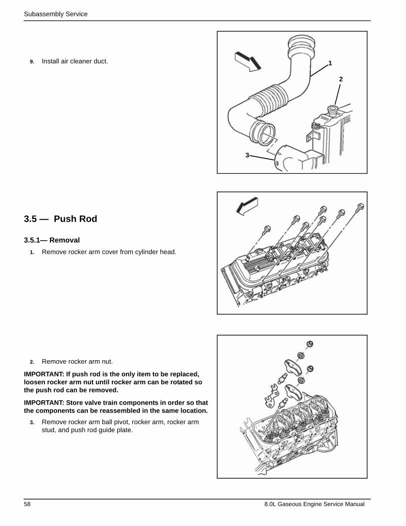
Subassembly Service
9. Install air cleaner duct.
3.5 — Push Rod
3.5.1— Removal
1. Remove rocker arm cover from cylinder head.
2. Remove rocker arm nut.
IMPORTANT: If push rod is the only item to be replaced, loosen rocker arm nut until rocker arm can be rotated so the push rod can be removed.
IMPORTANT: Store valve train components in order so that the components can be reassembled in the same location.
3. Remove rocker arm ball pivot, rocker arm, rocker arm stud, and push rod guide plate.
3
2
1
58 8.0L Gaseous Engine Service Manual
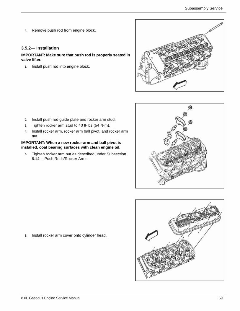
Subassembly Service
4. Remove push rod from engine block.
3.5.2— Installation
IMPORTANT: Make sure that push rod is properly seated in valve lifter.
1. Install push rod into engine block.
2. Install push rod guide plate and rocker arm stud.
3. Tighten rocker arm stud to 40 ft-lbs (54 N-m).
4. Install rocker arm, rocker arm ball pivot, and rocker arm nut.
IMPORTANT: When a new rocker arm and ball pivot is installed, coat bearing surfaces with clean engine oil.
5. Tighten rocker arm nut as described under Subsection 6.14 —Push Rods/Rocker Arms.
6. Install rocker arm cover onto cylinder head.
8.0L Gaseous Engine Service Manual 59

Subassembly Service
3.6 — Valves
3.6.1— Removal
Tools Required
• J 5892-C Valve Spring Compressor
• J 22794 Spark Plug Port Adapter
1. Remove rocker arm cover from cylinder head.
2. Rotate crankshaft until both valves are closed before installing the compressed air into the cylinder being ser-viced.
3. Remove rocker arm nuts.
4. Remove rocker arm ball pivots, rocker arms, rocker arm studs, and push rod guide plates.
5. Remove push rods from cylinder head.
6. Remove spark plugs from cylinder head.
60 8.0L Gaseous Engine Service Manual
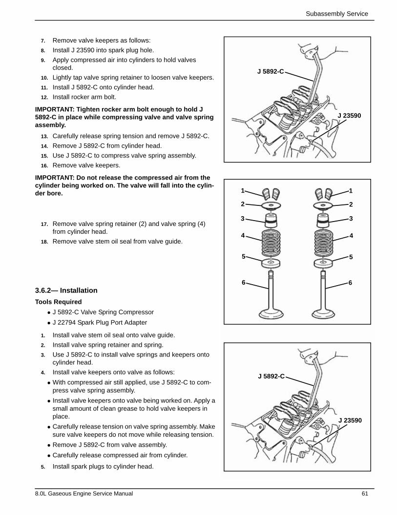
Subassembly Service
7. Remove valve keepers as follows:
8. Install J 23590 into spark plug hole.
9. Apply compressed air into cylinders to hold valves closed.
10. Lightly tap valve spring retainer to loosen valve keepers.
11. Install J 5892-C onto cylinder head.
12. Install rocker arm bolt.
IMPORTANT: Tighten rocker arm bolt enough to hold J 5892-C in place while compressing valve and valve spring assembly.
13. Carefully release spring tension and remove J 5892-C.
14. Remove J 5892-C from cylinder head.
15. Use J 5892-C to compress valve spring assembly.
16. Remove valve keepers.
IMPORTANT: Do not release the compressed air from the cylinder being worked on. The valve will fall into the cylin-der bore.
17. Remove valve spring retainer (2) and valve spring (4) from cylinder head.
18. Remove valve stem oil seal from valve guide.
3.6.2— Installation
Tools Required
• J 5892-C Valve Spring Compressor
• J 22794 Spark Plug Port Adapter
1. Install valve stem oil seal onto valve guide.
2. Install valve spring retainer and spring.
3. Use J 5892-C to install valve springs and keepers onto cylinder head.
4. Install valve keepers onto valve as follows:
• With compressed air still applied, use J 5892-C to com-press valve spring assembly.
• Install valve keepers onto valve being worked on. Apply a small amount of clean grease to hold valve keepers in place.
• Carefully release tension on valve spring assembly. Make sure valve keepers do not move while releasing tension.
• Remove J 5892-C from valve assembly.
• Carefully release compressed air from cylinder.
5. Install spark plugs to cylinder head.
J 23590
J 5892-C
J 23590
J 5892-C
1 1
2
3
4
5
6
2
3
4
5
6
8.0L Gaseous Engine Service Manual 61
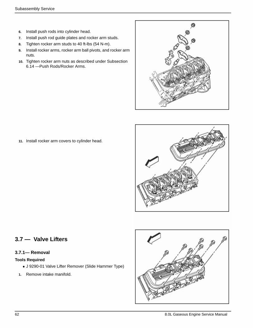
Subassembly Service
6. Install push rods into cylinder head.
7. Install push rod guide plates and rocker arm studs.
8. Tighten rocker arm studs to 40 ft-lbs (54 N-m).
9. Install rocker arms, rocker arm ball pivots, and rocker arm nuts.
10. Tighten rocker arm nuts as described under Subsection 6.14 —Push Rods/Rocker Arms.
11. Install rocker arm covers to cylinder head.
3.7 — Valve Lifters
3.7.1— Removal
Tools Required
• J 9290-01 Valve Lifter Remover (Slide Hammer Type)
1. Remove intake manifold.
62 8.0L Gaseous Engine Service Manual
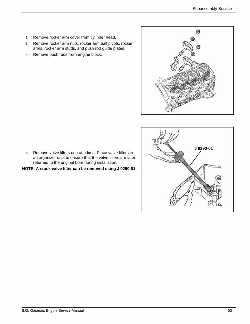
Subassembly Service
2. Remove rocker arm cover from cylinder head.
3. Remove rocker arm nuts, rocker arm ball pivots, rocker arms, rocker arm studs, and push rod guide plates.
4. Remove push rods from engine block.
5. Remove valve lifters one at a time. Place valve lifters in an organizer rack to ensure that the valve lifters are later returned to the original bore during installation.
NOTE: A stuck valve lifter can be removed using J 9290-01.
J 9290-01
8.0L Gaseous Engine Service Manual 63

Subassembly Service
3.7.2— Installation
IMPORTANT: Replace engine oil and oil filter if new valve lifters or a new camshaft is installed.
1. Install valve lifters and guide into engine block. Lubricate valve lifter and body with clean engine oil.
2. Install push rods into engine block.
3. Install push rod guide plates and rocker arm studs.
4. Tighten rocker arm studs to 40 ft-lbs (54 N-m).
5. Install rocker arms, rocker arm ball pivots, and rocker arm nuts.
6. Tighten rocker arm nuts as described under Subsection 6.14 —Push Rods/Rocker Arms.
7. Install rocker arm cover to cylinder head.
8. Install intake manifold to engine.
3.8 — Oil Level Indicator Tube
3.8.1— Removal
1. Remove retaining nut of oil level indicator tube.
2. Remove oil level indicator and tube from engine block.
64 8.0L Gaseous Engine Service Manual
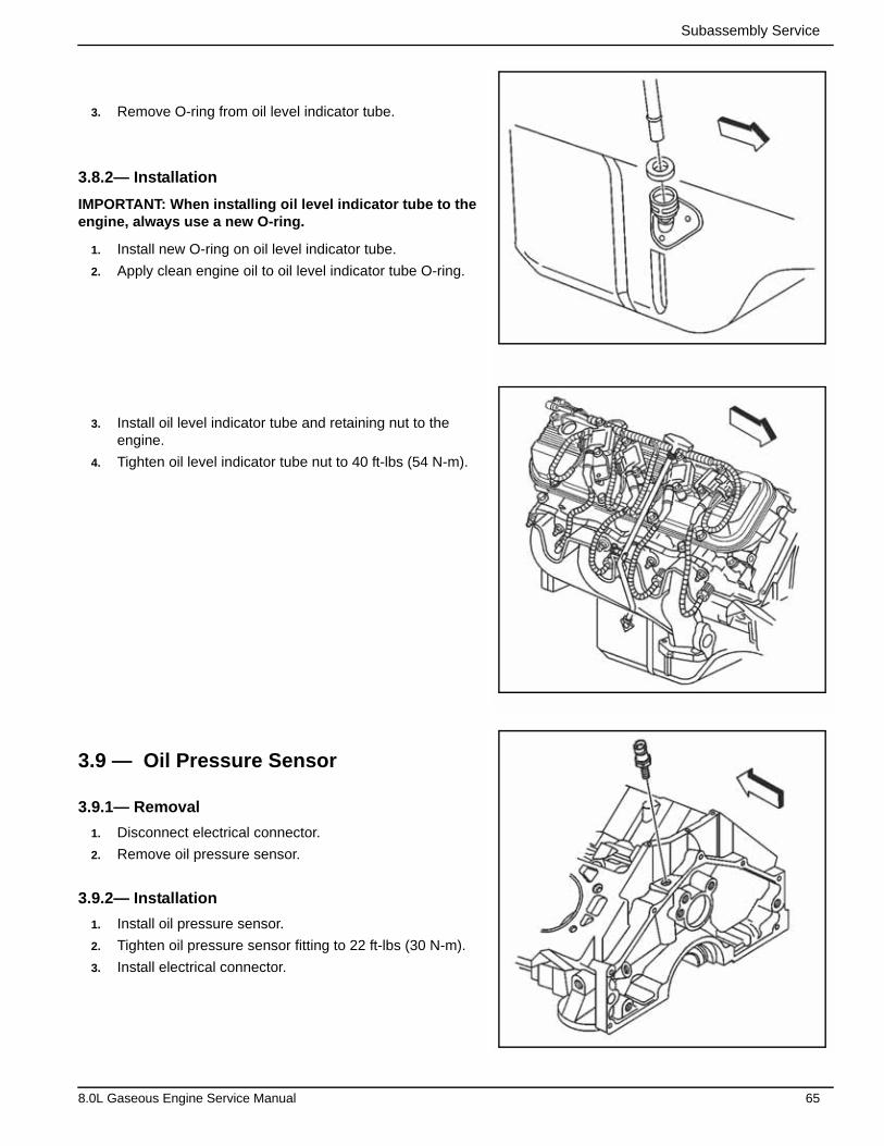
Subassembly Service
3. Remove O-ring from oil level indicator tube.
3.8.2— Installation
IMPORTANT: When installing oil level indicator tube to the engine, always use a new O-ring.
1. Install new O-ring on oil level indicator tube.
2. Apply clean engine oil to oil level indicator tube O-ring.
3. Install oil level indicator tube and retaining nut to the engine.
4. Tighten oil level indicator tube nut to 40 ft-lbs (54 N-m).
3.9 — Oil Pressure Sensor
3.9.1— Removal
1. Disconnect electrical connector.
2. Remove oil pressure sensor.
3.9.2— Installation
1. Install oil pressure sensor.
2. Tighten oil pressure sensor fitting to 22 ft-lbs (30 N-m).
3. Install electrical connector.
8.0L Gaseous Engine Service Manual 65
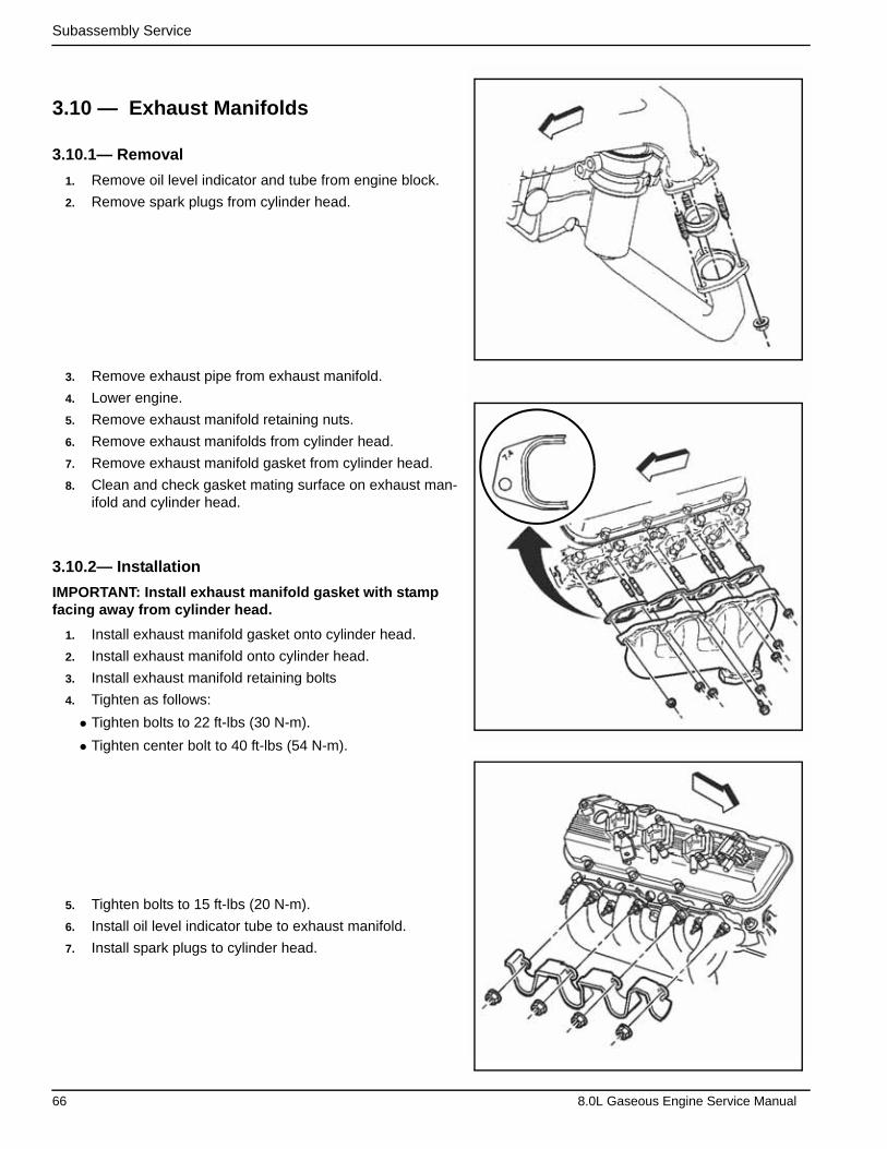
Subassembly Service
3.10 — Exhaust Manifolds
3.10.1— Removal
1. Remove oil level indicator and tube from engine block.
2. Remove spark plugs from cylinder head.
3. Remove exhaust pipe from exhaust manifold.
4. Lower engine.
5. Remove exhaust manifold retaining nuts.
6. Remove exhaust manifolds from cylinder head.
7. Remove exhaust manifold gasket from cylinder head.
8. Clean and check gasket mating surface on exhaust man-ifold and cylinder head.
3.10.2— Installation
IMPORTANT: Install exhaust manifold gasket with stamp facing away from cylinder head.
1. Install exhaust manifold gasket onto cylinder head.
2. Install exhaust manifold onto cylinder head.
3. Install exhaust manifold retaining bolts
4. Tighten as follows:
• Tighten bolts to 22 ft-lbs (30 N-m).
• Tighten center bolt to 40 ft-lbs (54 N-m).
5. Tighten bolts to 15 ft-lbs (20 N-m).
6. Install oil level indicator tube to exhaust manifold.
7. Install spark plugs to cylinder head.
66 8.0L Gaseous Engine Service Manual

Subassembly Service
8. Install exhaust pipes to exhaust manifolds.
3.11 — Cylinder Heads
3.11.1— Removal
1. Drain cooling system.
2. Remove engine electrical wiring harness.
3. Disconnect engine ground straps.
4. Remove generator from mounting bracket.
5. Remove generator mounting bracket from engine block.
6. Remove intake manifold.
7. Remove rocker arm covers from cylinder heads.
8. Remove rocker arm nuts, rocker arm ball pivots, rocker arms, rocker arm studs, and push rod guide plates.
9. Remove push rods from engine block.
10. Remove spark plugs from cylinder heads.
11. Remove exhaust manifolds from cylinder head.
8.0L Gaseous Engine Service Manual 67
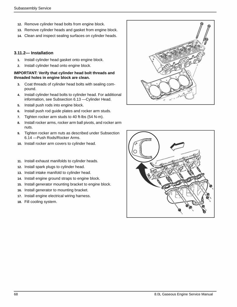
Subassembly Service
12. Remove cylinder head bolts from engine block.
13. Remove cylinder heads and gasket from engine block.
14. Clean and inspect sealing surfaces on cylinder heads.
3.11.2— Installation
1. Install cylinder head gasket onto engine block.
2. Install cylinder head onto engine block.
IMPORTANT: Verify that cylinder head bolt threads and threaded holes in engine block are clean.
3. Coat threads of cylinder head bolts with sealing com-pound.
4. Install cylinder head bolts to cylinder head. For additional information, see Subsection 6.13 —Cylinder Head.
5. Install push rods into engine block.
6. Install push rod guide plates and rocker arm studs.
7. Tighten rocker arm studs to 40 ft-lbs (54 N-m).
8. Install rocker arms, rocker arm ball pivots, and rocker arm nuts.
9. Tighten rocker arm nuts as described under Subsection 6.14 —Push Rods/Rocker Arms.
10. Install rocker arm covers to cylinder head.
11. Install exhaust manifolds to cylinder heads.
12. Install spark plugs to cylinder head.
13. Install intake manifold to cylinder head.
14. Install engine ground straps to engine block.
15. Install generator mounting bracket to engine block.
16. Install generator to mounting bracket.
17. Install engine electrical wiring harness.
18. Fill cooling system.
68 8.0L Gaseous Engine Service Manual
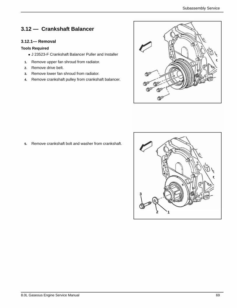
Subassembly Service
3.12 — Crankshaft Balancer
3.12.1— Removal
Tools Required
• J 23523-F Crankshaft Balancer Puller and Installer
1. Remove upper fan shroud from radiator.
2. Remove drive belt.
3. Remove lower fan shroud from radiator.
4. Remove crankshaft pulley from crankshaft balancer.
5. Remove crankshaft bolt and washer from crankshaft.
3
2 1
8.0L Gaseous Engine Service Manual 69
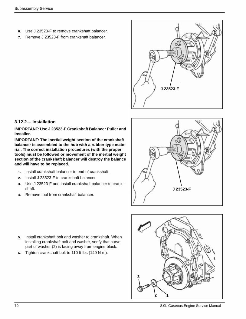
Subassembly Service
6. Use J 23523-F to remove crankshaft balancer.
7. Remove J 23523-F from crankshaft balancer.
3.12.2— Installation
IMPORTANT: Use J 23523-F Crankshaft Balancer Puller and Installer.
IMPORTANT: The inertial weight section of the crankshaft balancer is assembled to the hub with a rubber type mate-rial. The correct installation procedures (with the proper tools) must be followed or movement of the inertial weight section of the crankshaft balancer will destroy the balance and will have to be replaced.
1. Install crankshaft balancer to end of crankshaft.
2. Install J 23523-F to crankshaft balancer.
3. Use J 23523-F and install crankshaft balancer to crank-shaft.
4. Remove tool from crankshaft balancer.
5. Install crankshaft bolt and washer to crankshaft. When installing crankshaft bolt and washer, verify that curve part of washer (2) is facing away from engine block.
6. Tighten crankshaft bolt to 110 ft-lbs (149 N-m).
J 23523-F
J 23523-F
3
2 1
70 8.0L Gaseous Engine Service Manual
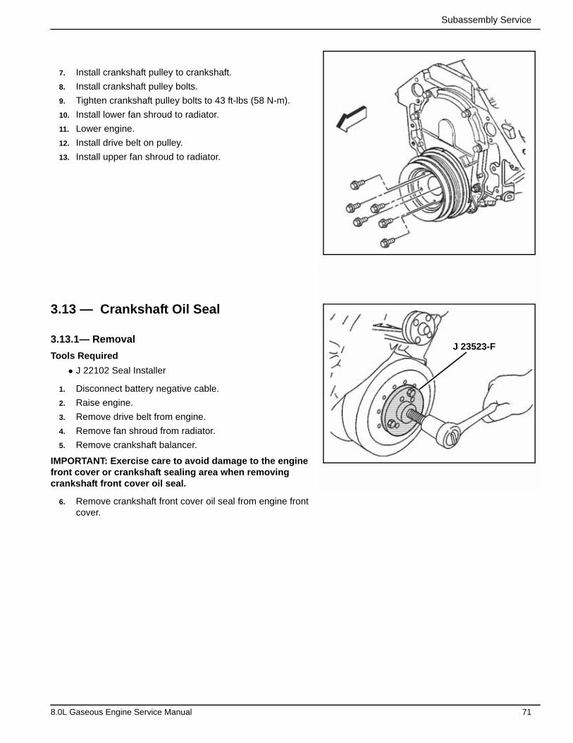
Subassembly Service
7. Install crankshaft pulley to crankshaft.
8. Install crankshaft pulley bolts.
9. Tighten crankshaft pulley bolts to 43 ft-lbs (58 N-m).
10. Install lower fan shroud to radiator.
11. Lower engine.
12. Install drive belt on pulley.
13. Install upper fan shroud to radiator.
3.13 — Crankshaft Oil Seal
3.13.1— Removal
Tools Required
• J 22102 Seal Installer
1. Disconnect battery negative cable.
2. Raise engine.
3. Remove drive belt from engine.
4. Remove fan shroud from radiator.
5. Remove crankshaft balancer.
IMPORTANT: Exercise care to avoid damage to the engine front cover or crankshaft sealing area when removing crankshaft front cover oil seal.
6. Remove crankshaft front cover oil seal from engine front cover.
J 23523-F
8.0L Gaseous Engine Service Manual 71
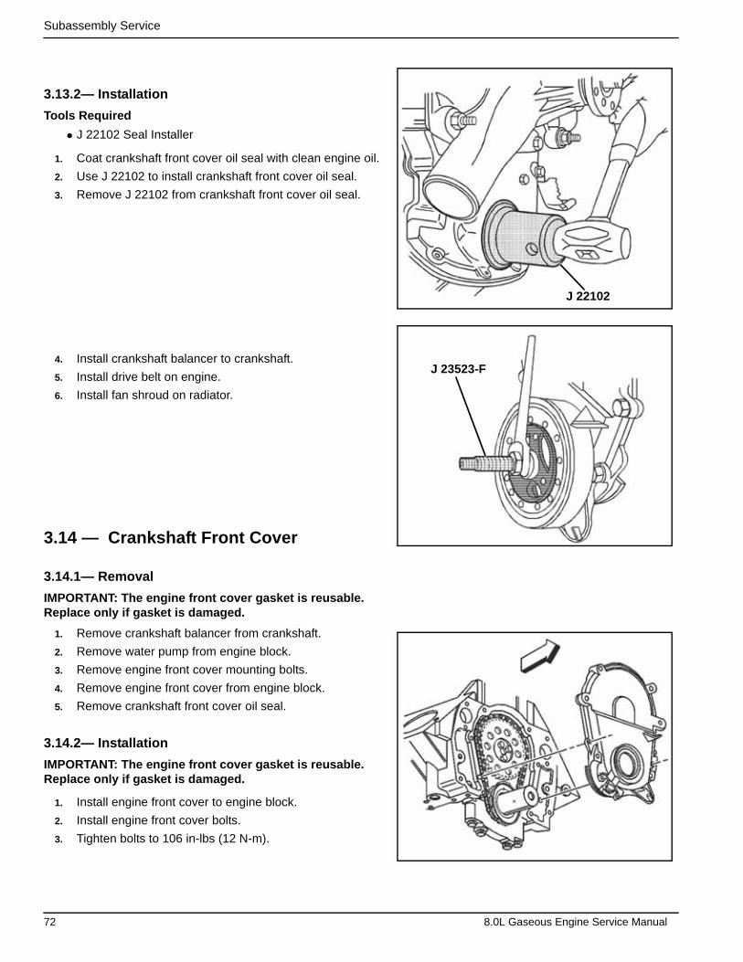
Subassembly Service
3.13.2— Installation
Tools Required
• J 22102 Seal Installer
1. Coat crankshaft front cover oil seal with clean engine oil.
2. Use J 22102 to install crankshaft front cover oil seal.
3. Remove J 22102 from crankshaft front cover oil seal.
4. Install crankshaft balancer to crankshaft.
5. Install drive belt on engine.
6. Install fan shroud on radiator.
3.14 — Crankshaft Front Cover
3.14.1— Removal
IMPORTANT: The engine front cover gasket is reusable. Replace only if gasket is damaged.
1. Remove crankshaft balancer from crankshaft.
2. Remove water pump from engine block.
3. Remove engine front cover mounting bolts.
4. Remove engine front cover from engine block.
5. Remove crankshaft front cover oil seal.
3.14.2— Installation
IMPORTANT: The engine front cover gasket is reusable. Replace only if gasket is damaged.
1. Install engine front cover to engine block.
2. Install engine front cover bolts.
3. Tighten bolts to 106 in-lbs (12 N-m).
J 23523-F
J 22102
72 8.0L Gaseous Engine Service Manual
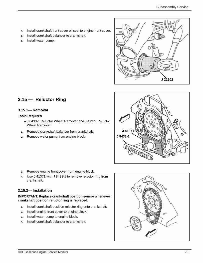
Subassembly Service
4. Install crankshaft front cover oil seal to engine front cover.
5. Install crankshaft balancer to crankshaft.
6. Install water pump.
3.15 — Reluctor Ring
3.15.1— Removal
Tools Required
• J 8433-1 Reluctor Wheel Remover and J 41371 Reluctor Wheel Remover
1. Remove crankshaft balancer from crankshaft.
2. Remove water pump from engine block.
3. Remove engine front cover from engine block.
4. Use J 41371 with J 8433-1 to remove reluctor ring from crankshaft.
3.15.2— Installation
IMPORTANT: Replace crankshaft position sensor whenever crankshaft position reluctor ring is replaced.
1. Install crankshaft position reluctor ring onto crankshaft.
2. Install engine front cover to engine block.
3. Install water pump to engine block.
4. Install crankshaft balancer to crankshaft.
J 22102
J 8433-1
J 41371
8.0L Gaseous Engine Service Manual 73
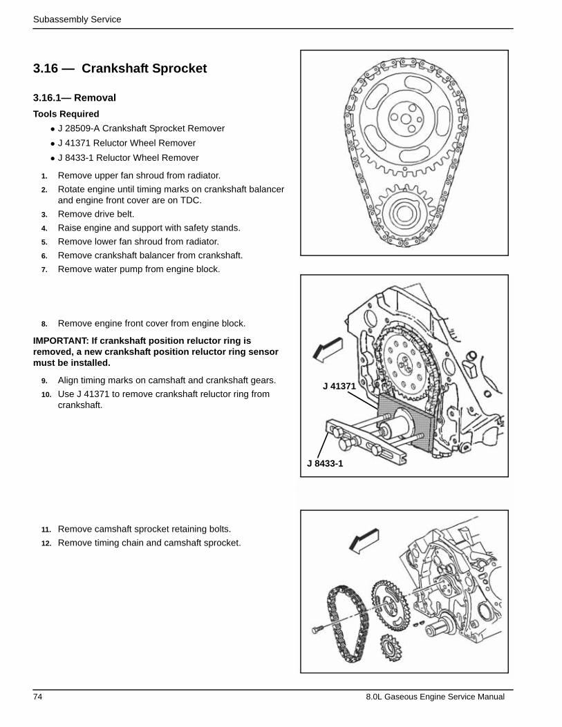
Subassembly Service
3.16 — Crankshaft Sprocket
3.16.1— Removal
Tools Required
• J 28509-A Crankshaft Sprocket Remover
• J 41371 Reluctor Wheel Remover
• J 8433-1 Reluctor Wheel Remover
1. Remove upper fan shroud from radiator.
2. Rotate engine until timing marks on crankshaft balancer and engine front cover are on TDC.
3. Remove drive belt.
4. Raise engine and support with safety stands.
5. Remove lower fan shroud from radiator.
6. Remove crankshaft balancer from crankshaft.
7. Remove water pump from engine block.
8. Remove engine front cover from engine block.
IMPORTANT: If crankshaft position reluctor ring is removed, a new crankshaft position reluctor ring sensor must be installed.
9. Align timing marks on camshaft and crankshaft gears.
10. Use J 41371 to remove crankshaft reluctor ring from crankshaft.
11. Remove camshaft sprocket retaining bolts.
12. Remove timing chain and camshaft sprocket.
J 8433-1
J 41371
74 8.0L Gaseous Engine Service Manual
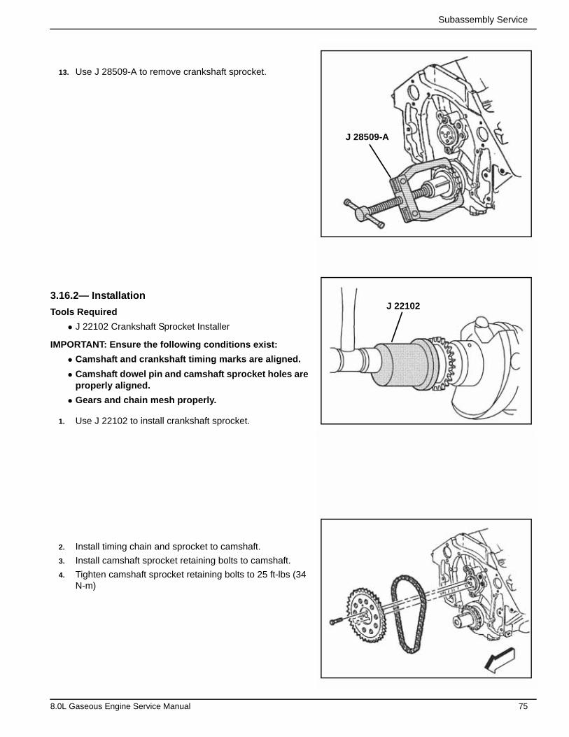
Subassembly Service
13. Use J 28509-A to remove crankshaft sprocket.
3.16.2— Installation
Tools Required
• J 22102 Crankshaft Sprocket Installer
IMPORTANT: Ensure the following conditions exist:
• Camshaft and crankshaft timing marks are aligned.
• Camshaft dowel pin and camshaft sprocket holes are properly aligned.
• Gears and chain mesh properly.
1. Use J 22102 to install crankshaft sprocket.
2. Install timing chain and sprocket to camshaft.
3. Install camshaft sprocket retaining bolts to camshaft.
4. Tighten camshaft sprocket retaining bolts to 25 ft-lbs (34 N-m)
J 22102
J 28509-A
8.0L Gaseous Engine Service Manual 75
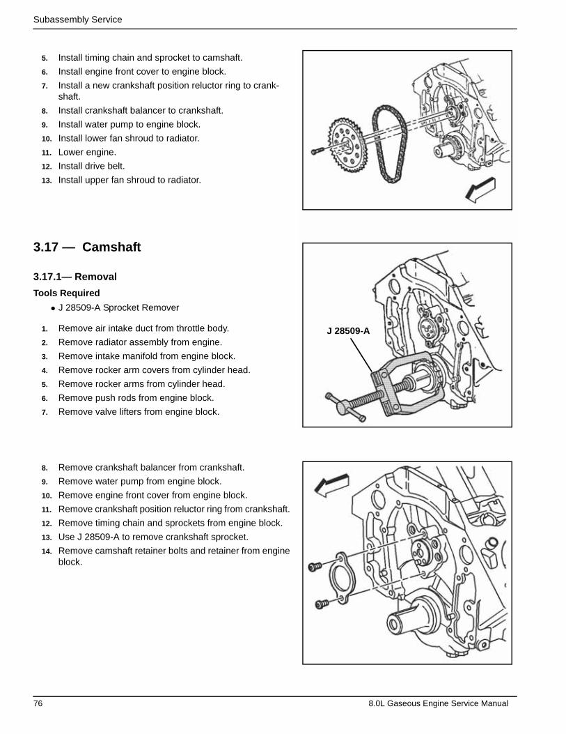
Subassembly Service
5. Install timing chain and sprocket to camshaft.
6. Install engine front cover to engine block.
7. Install a new crankshaft position reluctor ring to crank-shaft.
8. Install crankshaft balancer to crankshaft.
9. Install water pump to engine block.
10. Install lower fan shroud to radiator.
11. Lower engine.
12. Install drive belt.
13. Install upper fan shroud to radiator.
3.17 — Camshaft
3.17.1— Removal
Tools Required
• J 28509-A Sprocket Remover
1. Remove air intake duct from throttle body.
2. Remove radiator assembly from engine.
3. Remove intake manifold from engine block.
4. Remove rocker arm covers from cylinder head.
5. Remove rocker arms from cylinder head.
6. Remove push rods from engine block.
7. Remove valve lifters from engine block.
8. Remove crankshaft balancer from crankshaft.
9. Remove water pump from engine block.
10. Remove engine front cover from engine block.
11. Remove crankshaft position reluctor ring from crankshaft.
12. Remove timing chain and sprockets from engine block.
13. Use J 28509-A to remove crankshaft sprocket.
14. Remove camshaft retainer bolts and retainer from engine block.
J 28509-A
76 8.0L Gaseous Engine Service Manual
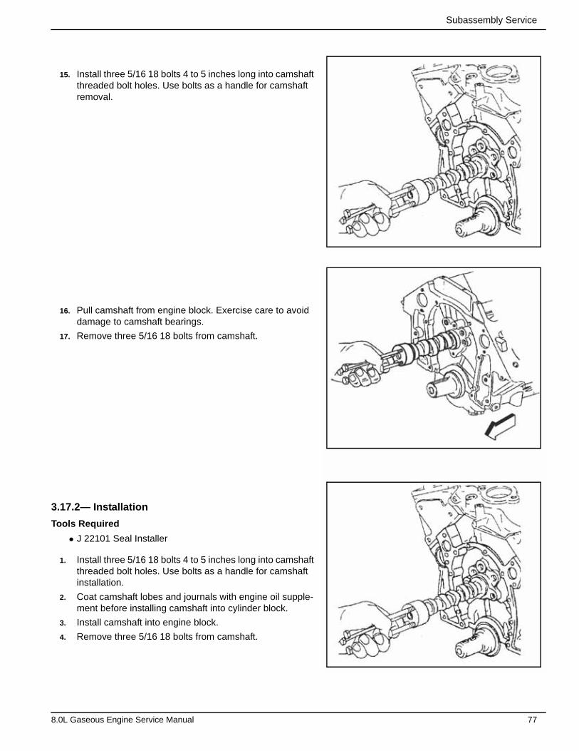
Subassembly Service
15. Install three 5/16 18 bolts 4 to 5 inches long into camshaft threaded bolt holes. Use bolts as a handle for camshaft removal.
16. Pull camshaft from engine block. Exercise care to avoid damage to camshaft bearings.
17. Remove three 5/16 18 bolts from camshaft.
3.17.2— Installation
Tools Required
• J 22101 Seal Installer
1. Install three 5/16 18 bolts 4 to 5 inches long into camshaft threaded bolt holes. Use bolts as a handle for camshaft installation.
2. Coat camshaft lobes and journals with engine oil supple-ment before installing camshaft into cylinder block.
3. Install camshaft into engine block.
4. Remove three 5/16 18 bolts from camshaft.
8.0L Gaseous Engine Service Manual 77

Subassembly Service
5. Install camshaft retainer and bolts in engine block.
6. Tighten bolts to 106 in-lbs (12 N-m).
7. Use J 22102 to install crankshaft sprocket.
8. Install timing chain and camshaft sprocket to camshaft.
9. Install camshaft sprocket bolts to camshaft.
10. Tighten bolts to 22 ft-lbs (30 N-m).
11. Install crankshaft position reluctor ring on crankshaft.
12. Install engine front cover to engine block.
13. Install water pump to engine block.
14. Install crankshaft balancer to crankshaft.
15. Install drive belt.
16. Install valve lifters to engine block.
17. Install push rods into engine block.
18. Install rocker arms to cylinder head.
19. Install intake manifold to engine block.
20. Install rocker arm covers to cylinder head.
21. Install air cleaner duct to throttle body.
22. Install radiator.
J 22102
78 8.0L Gaseous Engine Service Manual
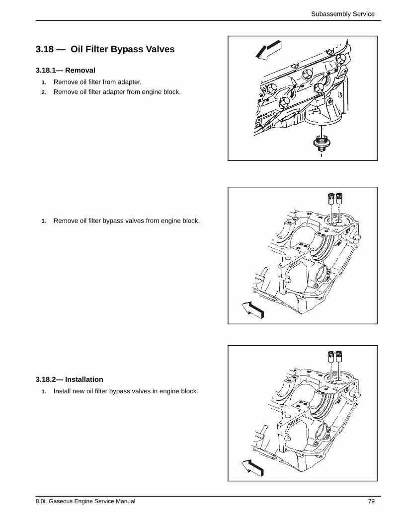
Subassembly Service
3.18 — Oil Filter Bypass Valves
3.18.1— Removal
1. Remove oil filter from adapter.
2. Remove oil filter adapter from engine block.
3. Remove oil filter bypass valves from engine block.
3.18.2— Installation
1. Install new oil filter bypass valves in engine block.
8.0L Gaseous Engine Service Manual 79

Subassembly Service
2. Install oil filter adapter to engine block.
3. Install oil filter to adapter.
3.19 — Oil Pan
3.19.1— Removal
1. Remove oil level indicator and tube from engine.
2. Drain crankcase.
3. Remove starter from engine block.
IMPORTANT: DO NOT lift engine by crankshaft balancer to aide in removing oil pan from engine block. Damage to crankshaft balancer or crankshaft can occur.
4. Remove flywheel from crankshaft.
80 8.0L Gaseous Engine Service Manual
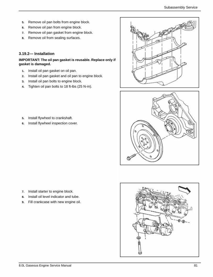
Subassembly Service
5. Remove oil pan bolts from engine block.
6. Remove oil pan from engine block.
7. Remove oil pan gasket from engine block.
8. Remove oil from sealing surfaces.
3.19.2— Installation
IMPORTANT: The oil pan gasket is reusable. Replace only if gasket is damaged.
1. Install oil pan gasket on oil pan.
2. Install oil pan gasket and oil pan to engine block.
3. Install oil pan bolts to engine block.
4. Tighten oil pan bolts to 18 ft-lbs (25 N-m).
5. Install flywheel to crankshaft.
6. Install flywheel inspection cover.
7. Install starter to engine block.
8. Install oil level indicator and tube.
9. Fill crankcase with new engine oil.
8.0L Gaseous Engine Service Manual 81
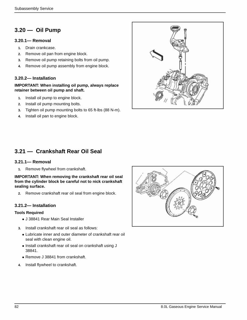
Subassembly Service
3.20 — Oil Pump
3.20.1— Removal
1. Drain crankcase.
2. Remove oil pan from engine block.
3. Remove oil pump retaining bolts from oil pump.
4. Remove oil pump assembly from engine block.
3.20.2— Installation
IMPORTANT: When installing oil pump, always replace retainer between oil pump and shaft.
1. Install oil pump to engine block.
2. Install oil pump mounting bolts.
3. Tighten oil pump mounting bolts to 65 ft-lbs (88 N-m).
4. Install oil pan to engine block.
3.21 — Crankshaft Rear Oil Seal
3.21.1— Removal
1. Remove flywheel from crankshaft.
IMPORTANT: When removing the crankshaft rear oil seal from the cylinder block be careful not to nick crankshaft sealing surface.
2. Remove crankshaft rear oil seal from engine block.
3.21.2— Installation
Tools Required
• J 38841 Rear Main Seal Installer
3. Install crankshaft rear oil seal as follows:
• Lubricate inner and outer diameter of crankshaft rear oil seal with clean engine oil.
• Install crankshaft rear oil seal on crankshaft using J 38841.
• Remove J 38841 from crankshaft.
4. Install flywheel to crankshaft.
82 8.0L Gaseous Engine Service Manual

Subassembly Service
3.22 — Flywheel
3.22.1— Removal
IMPORTANT: If replacing the flywheel, note location of any existing balance weights (if applicable). Install new balance weights into new flywheel (if applicable). Flywheel balance weights must be installed into the new flywheel in the same locations as the old flywheel. A properly installed balance weight will be either flush or below flush with the face of the flywheel.
1. Remove flywheel from crankshaft.
2. Remove any burrs from end of crankshaft.
3.22.2— Installation
1. Install flywheel to crankshaft.
2. Install flywheel mounting bolts.
3. Tighten flywheel mounting bolts to 65 ft-lbs (88 N-m).
4. Install flywheel (manual) to crankshaft.
5. Tighten bolts to 65 ft-lbs (88 N-m).
3.23 — Lift Brackets
3.23.1— Removal
Tools Required
• J 36857 Engine Lift Brackets
1. Remove air cleaner duct from throttle body.
2. Drain cooling system.
3. Disconnect electrical connectors on throttle body.
4. Remove generator from generator mounting bracket.
5. Remove engine electrical harness and tie out of the way.
6. Remove ground wires from engine block.
7. Remove starter motor from engine block.
1
8.0L Gaseous Engine Service Manual 83

Subassembly Service
8. Remove flywheel inspection cover.
9. Remove exhaust pipes.
10. Attach J 36857 to rear of right cylinder head and front of left cylinder head.
NOTE: Damage may result from use of an improper bolt.
11. Install attaching bolt and washer.
12. Tighten lift bracket bolt to 52 ft-lbs (70 N-m).
13. Remove front engine mount bolts.
14. Remove engine with a suitable lifting device.
15. Remove generator mounting bracket from engine block.
16. Remove lift brackets from cylinder head.
3.23.2— Installation
1. Attach J 36857 to rear of right cylinder head.
2. Install attaching bolt and washer.
3. Tighten lift bracket bolts to 52 ft-lbs (70 N-m).
J 36857
84 8.0L Gaseous Engine Service Manual
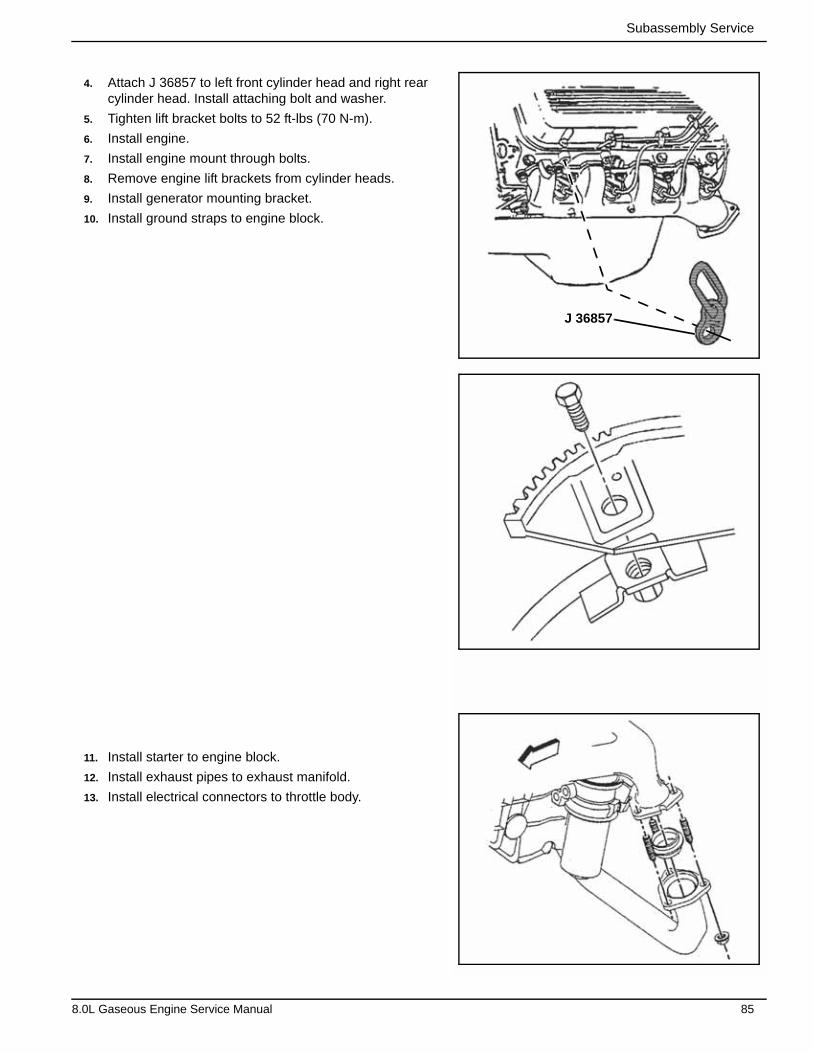
Subassembly Service
4. Attach J 36857 to left front cylinder head and right rear cylinder head. Install attaching bolt and washer.
5. Tighten lift bracket bolts to 52 ft-lbs (70 N-m).
6. Install engine.
7. Install engine mount through bolts.
8. Remove engine lift brackets from cylinder heads.
9. Install generator mounting bracket.
10. Install ground straps to engine block.
11. Install starter to engine block.
12. Install exhaust pipes to exhaust manifold.
13. Install electrical connectors to throttle body.
J 36857
8.0L Gaseous Engine Service Manual 85

Subassembly Service
14. Install generator to generator mounting bracket.
15. Install engine electrical wiring harness to engine.
16. Install air cleaner duct to throttle body.
17. Fill radiator with coolant.
18. Install oil filter and engine oil.
3.24 — Oil Pan Drain Plug
3.24.1— Removal
1. Remove oil filter from engine block. Clean oil filter mount-ing surfaces.
2. Remove oil pan drain plug and drain engine oil. Clean oil drain plug and mounting surface.
86 8.0L Gaseous Engine Service Manual
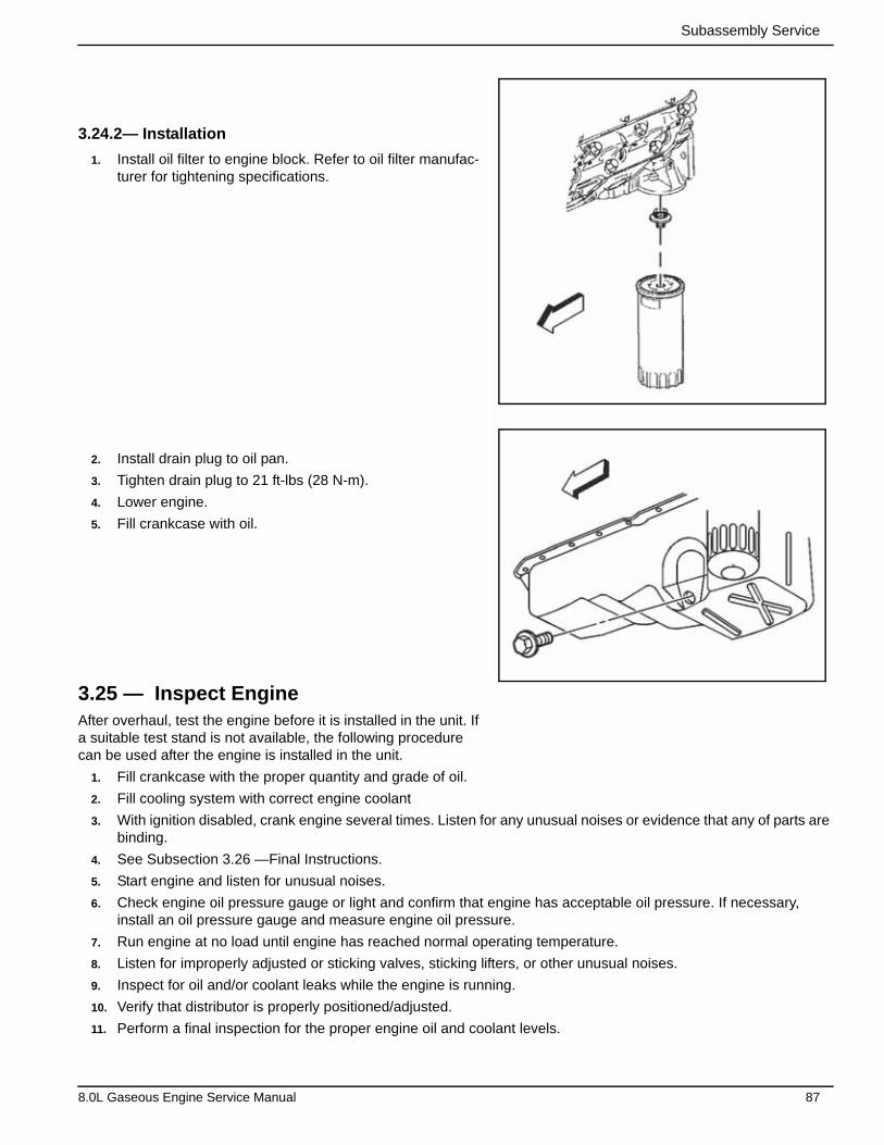
Subassembly Service
3.24.2— Installation
1. Install oil filter to engine block. Refer to oil filter manufac-turer for tightening specifications.
2. Install drain plug to oil pan.
3. Tighten drain plug to 21 ft-lbs (28 N-m).
4. Lower engine.
5. Fill crankcase with oil.
3.25 — Inspect EngineAfter overhaul, test the engine before it is installed in the unit. If a suitable test stand is not available, the following procedure can be used after the engine is installed in the unit.
1. Fill crankcase with the proper quantity and grade of oil.
2. Fill cooling system with correct engine coolant
3. With ignition disabled, crank engine several times. Listen for any unusual noises or evidence that any of parts are binding.
4. See Subsection 3.26 —Final Instructions.
5. Start engine and listen for unusual noises.
6. Check engine oil pressure gauge or light and confirm that engine has acceptable oil pressure. If necessary, install an oil pressure gauge and measure engine oil pressure.
7. Run engine at no load until engine has reached normal operating temperature.
8. Listen for improperly adjusted or sticking valves, sticking lifters, or other unusual noises.
9. Inspect for oil and/or coolant leaks while the engine is running.
10. Verify that distributor is properly positioned/adjusted.
11. Perform a final inspection for the proper engine oil and coolant levels.
8.0L Gaseous Engine Service Manual 87
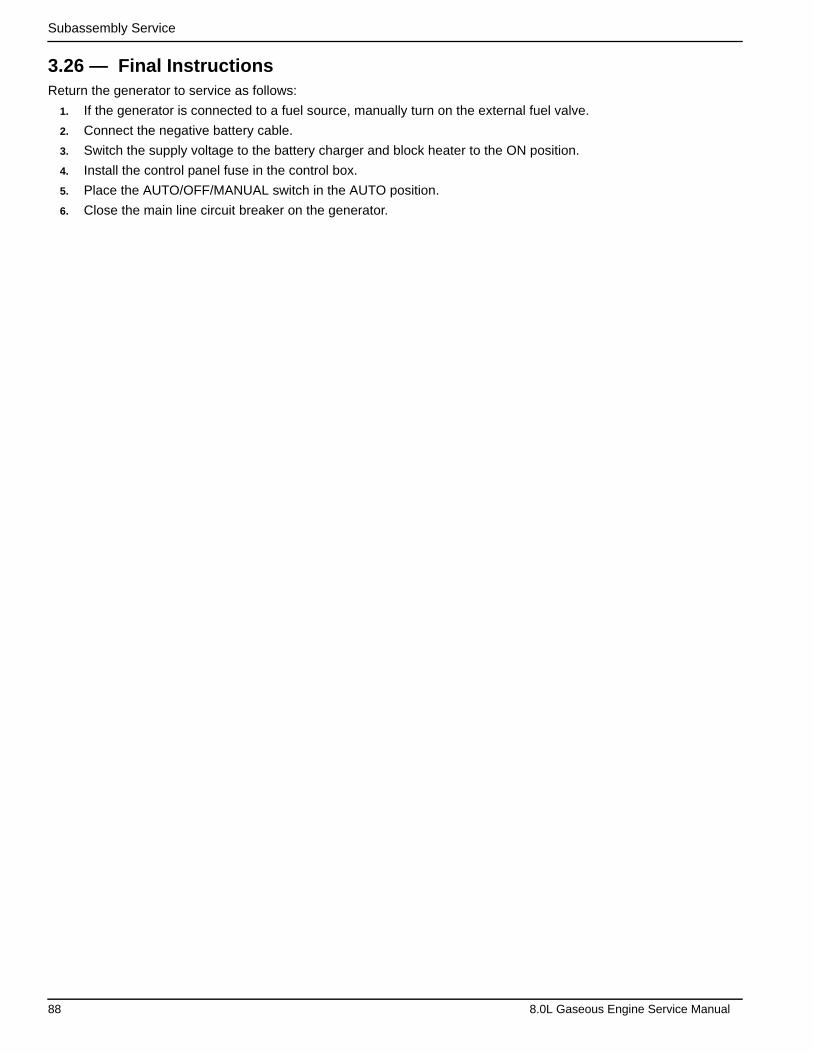
Subassembly Service
3.26 — Final InstructionsReturn the generator to service as follows:
1. If the generator is connected to a fuel source, manually turn on the external fuel valve.
2. Connect the negative battery cable.
3. Switch the supply voltage to the battery charger and block heater to the ON position.
4. Install the control panel fuse in the control box.
5. Place the AUTO/OFF/MANUAL switch in the AUTO position.
6. Close the main line circuit breaker on the generator.
88 8.0L Gaseous Engine Service Manual
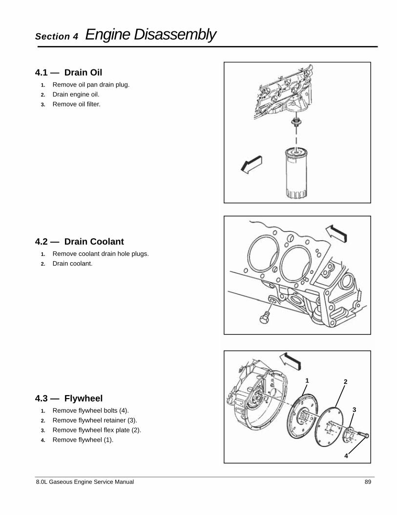
8.0L Gaseous Engine Service Manual 89
Section 4 Engine Disassembly
4.1 — Drain Oil1. Remove oil pan drain plug.
2. Drain engine oil.
3. Remove oil filter.
4.2 — Drain Coolant1. Remove coolant drain hole plugs.
2. Drain coolant.
4.3 — Flywheel1. Remove flywheel bolts (4).
2. Remove flywheel retainer (3).
3. Remove flywheel flex plate (2).
4. Remove flywheel (1).
1 2
3
4
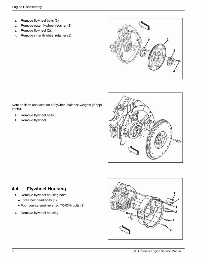
Engine Disassembly
1. Remove flywheel bolts (3).
2. Remove outer flywheel retainer (1).
3. Remove flywheel (2).
4. Remove inner flywheel retainer (1).
Note position and location of flywheel balance weights (if appli-cable).
1. Remove flywheel bolts.
2. Remove flywheel.
4.4 — Flywheel Housing1. Remove flywheel housing bolts.
• Three hex head bolts (1).
• Four countersunk inverted TORX® bolts (2).
2. Remove flywheel housing.
1
1
2
3
2
1
1
2
1
2
90 8.0L Gaseous Engine Service Manual

Engine Disassembly
1. Remove flywheel housing bolts.
2. Remove flywheel housing.
1. Remove flywheel housing adapter bolts.
2. Remove flywheel housing adapter.
4.5 — Oil Level Indicator1. Remove oil level indicator from oil level indicator tube.
2. Remove oil level indicator tube retaining clip.
8.0L Gaseous Engine Service Manual 91
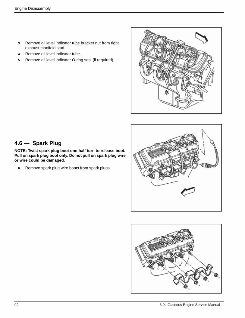
Engine Disassembly
3. Remove oil level indicator tube bracket nut from right exhaust manifold stud.
4. Remove oil level indicator tube.
5. Remove oil level indicator O-ring seal (if required).
4.6 — Spark PlugNOTE: Twist spark plug boot one-half turn to release boot. Pull on spark plug boot only. Do not pull on spark plug wire or wire could be damaged.
6. Remove spark plug wire boots from spark plugs.
92 8.0L Gaseous Engine Service Manual
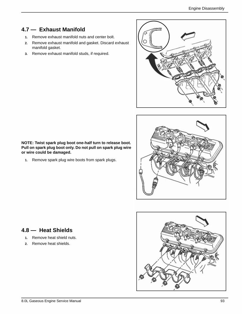
Engine Disassembly
4.7 — Exhaust Manifold1. Remove exhaust manifold nuts and center bolt.
2. Remove exhaust manifold and gasket. Discard exhaust manifold gasket.
3. Remove exhaust manifold studs, if required.
NOTE: Twist spark plug boot one-half turn to release boot. Pull on spark plug boot only. Do not pull on spark plug wire or wire could be damaged.
1. Remove spark plug wire boots from spark plugs.
4.8 — Heat Shields1. Remove heat shield nuts.
2. Remove heat shields.
8.0L Gaseous Engine Service Manual 93
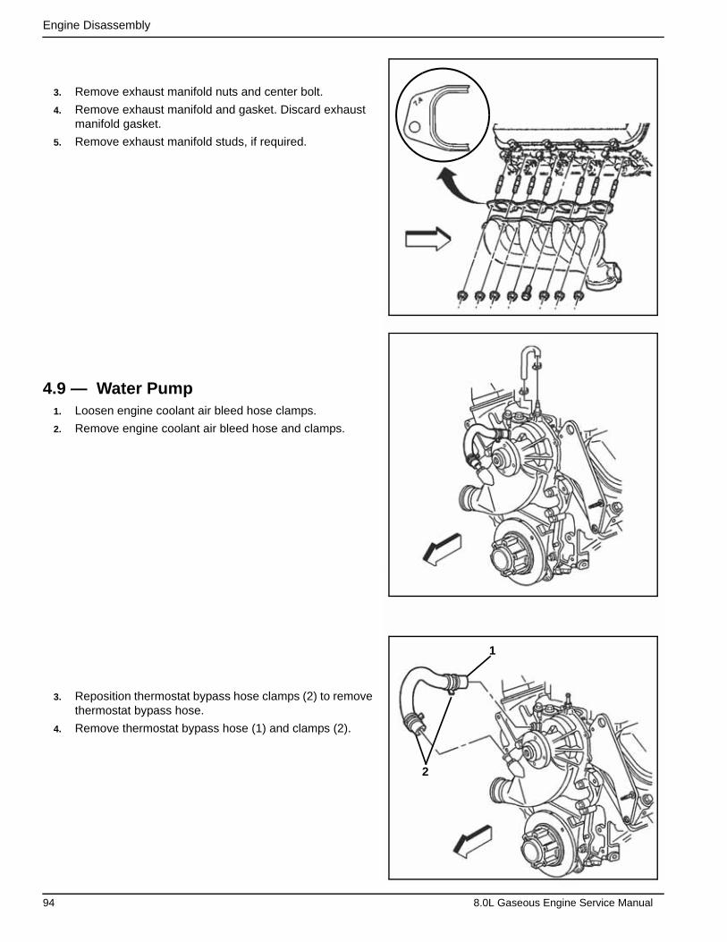
Engine Disassembly
3. Remove exhaust manifold nuts and center bolt.
4. Remove exhaust manifold and gasket. Discard exhaust manifold gasket.
5. Remove exhaust manifold studs, if required.
4.9 — Water Pump1. Loosen engine coolant air bleed hose clamps.
2. Remove engine coolant air bleed hose and clamps.
3. Reposition thermostat bypass hose clamps (2) to remove thermostat bypass hose.
4. Remove thermostat bypass hose (1) and clamps (2).
1
2
94 8.0L Gaseous Engine Service Manual
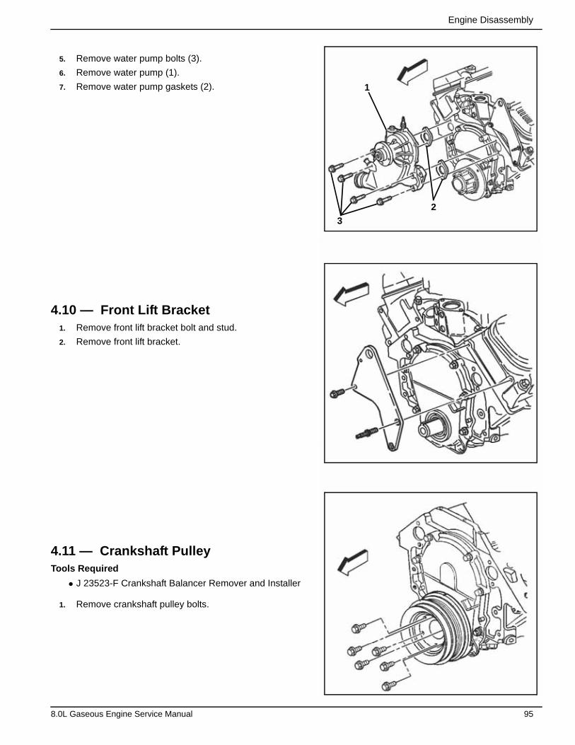
Engine Disassembly
5. Remove water pump bolts (3).
6. Remove water pump (1).
7. Remove water pump gaskets (2).
4.10 — Front Lift Bracket1. Remove front lift bracket bolt and stud.
2. Remove front lift bracket.
4.11 — Crankshaft PulleyTools Required
• J 23523-F Crankshaft Balancer Remover and Installer
1. Remove crankshaft pulley bolts.
1
2
3
8.0L Gaseous Engine Service Manual 95
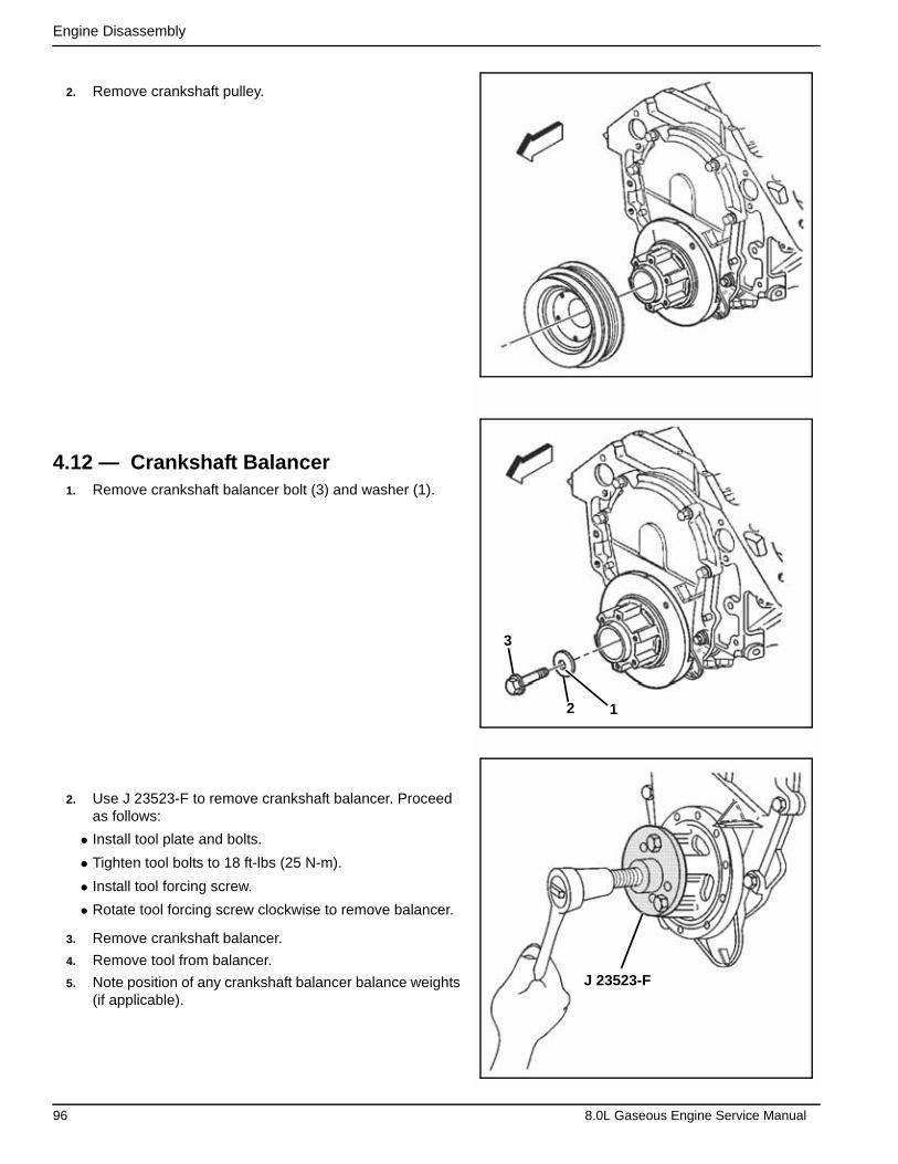
Engine Disassembly
2. Remove crankshaft pulley.
4.12 — Crankshaft Balancer1. Remove crankshaft balancer bolt (3) and washer (1).
2. Use J 23523-F to remove crankshaft balancer. Proceed as follows:
• Install tool plate and bolts.
• Tighten tool bolts to 18 ft-lbs (25 N-m).
• Install tool forcing screw.
• Rotate tool forcing screw clockwise to remove balancer.
3. Remove crankshaft balancer.
4. Remove tool from balancer.
5. Note position of any crankshaft balancer balance weights (if applicable).
J 23523-F
3
2 1
96 8.0L Gaseous Engine Service Manual
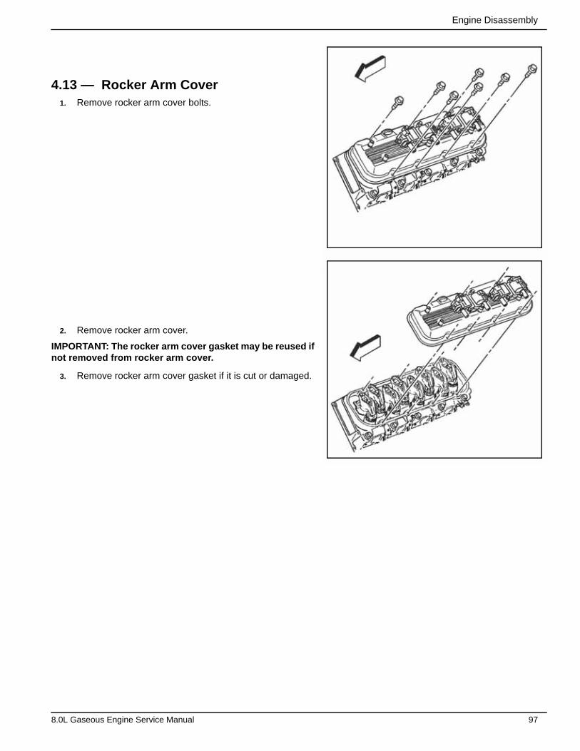
Engine Disassembly
4.13 — Rocker Arm Cover1. Remove rocker arm cover bolts.
2. Remove rocker arm cover.
IMPORTANT: The rocker arm cover gasket may be reused if not removed from rocker arm cover.
3. Remove rocker arm cover gasket if it is cut or damaged.
8.0L Gaseous Engine Service Manual 97
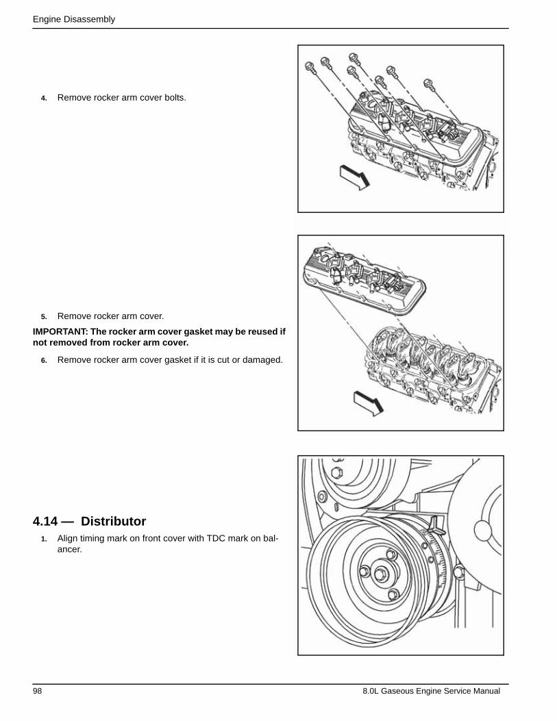
Engine Disassembly
4. Remove rocker arm cover bolts.
5. Remove rocker arm cover.
IMPORTANT: The rocker arm cover gasket may be reused if not removed from rocker arm cover.
6. Remove rocker arm cover gasket if it is cut or damaged.
4.14 — Distributor1. Align timing mark on front cover with TDC mark on bal-
ancer.
98 8.0L Gaseous Engine Service Manual
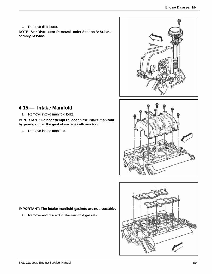
Engine Disassembly
2. Remove distributor.
NOTE: See Distributor Removal under Section 3: Subas-sembly Service.
4.15 — Intake Manifold1. Remove intake manifold bolts.
IMPORTANT: Do not attempt to loosen the intake manifold by prying under the gasket surface with any tool.
2. Remove intake manifold.
IMPORTANT: The intake manifold gaskets are not reusable.
3. Remove and discard intake manifold gaskets.
8.0L Gaseous Engine Service Manual 99

Engine Disassembly
4. Remove and discard intake manifold gaskets.
5. Remove and discard intake manifold seals.
100 8.0L Gaseous Engine Service Manual
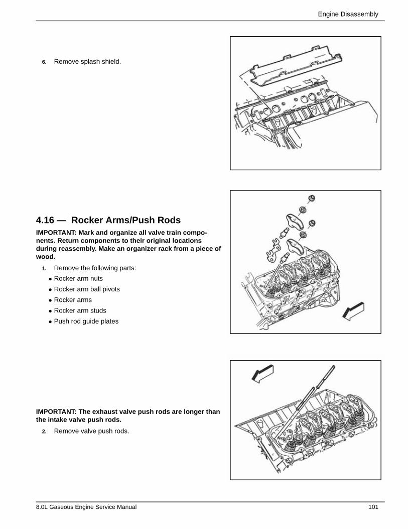
Engine Disassembly
6. Remove splash shield.
4.16 — Rocker Arms/Push RodsIMPORTANT: Mark and organize all valve train compo-nents. Return components to their original locations during reassembly. Make an organizer rack from a piece of wood.
1. Remove the following parts:
• Rocker arm nuts
• Rocker arm ball pivots
• Rocker arms
• Rocker arm studs
• Push rod guide plates
IMPORTANT: The exhaust valve push rods are longer than the intake valve push rods.
2. Remove valve push rods.
8.0L Gaseous Engine Service Manual 101
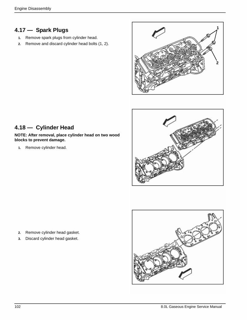
Engine Disassembly
4.17 — Spark Plugs1. Remove spark plugs from cylinder head.
2. Remove and discard cylinder head bolts (1, 2).
4.18 — Cylinder HeadNOTE: After removal, place cylinder head on two wood blocks to prevent damage.
1. Remove cylinder head.
2. Remove cylinder head gasket.
3. Discard cylinder head gasket.
2
1
102 8.0L Gaseous Engine Service Manual

Engine Disassembly
4. Remove cylinder head locating pins, if required.
1. Remove spark plugs from cylinder head.
2. Remove and discard cylinder head bolts (1, 2).
NOTE: After removal, place cylinder head on two wood blocks to prevent damage.
3. Remove cylinder head.
1
2
8.0L Gaseous Engine Service Manual 103
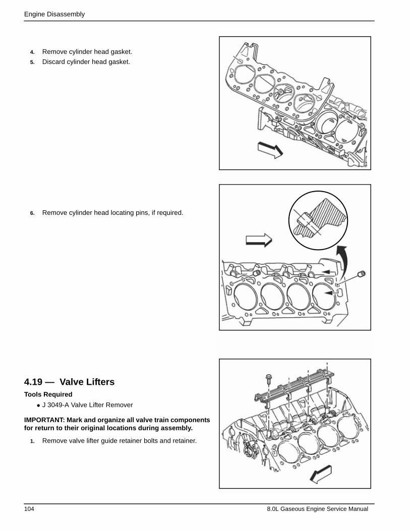
Engine Disassembly
4. Remove cylinder head gasket.
5. Discard cylinder head gasket.
6. Remove cylinder head locating pins, if required.
4.19 — Valve LiftersTools Required
• J 3049-A Valve Lifter Remover
IMPORTANT: Mark and organize all valve train components for return to their original locations during assembly.
1. Remove valve lifter guide retainer bolts and retainer.
104 8.0L Gaseous Engine Service Manual
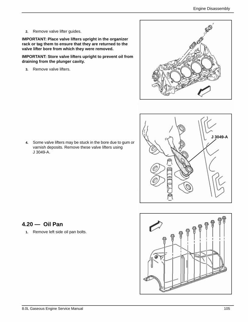
Engine Disassembly
2. Remove valve lifter guides.
IMPORTANT: Place valve lifters upright in the organizer rack or tag them to ensure that they are returned to the valve lifter bore from which they were removed.
IMPORTANT: Store valve lifters upright to prevent oil from draining from the plunger cavity.
3. Remove valve lifters.
4. Some valve lifters may be stuck in the bore due to gum or varnish deposits. Remove these valve lifters using J 3049-A.
4.20 — Oil Pan1. Remove left side oil pan bolts.
J 3049-A
8.0L Gaseous Engine Service Manual 105
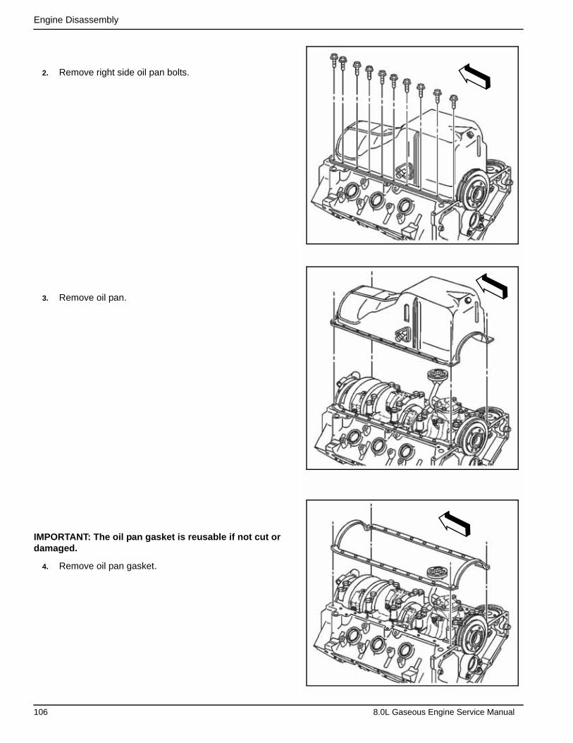
Engine Disassembly
2. Remove right side oil pan bolts.
3. Remove oil pan.
IMPORTANT: The oil pan gasket is reusable if not cut or damaged.
4. Remove oil pan gasket.
106 8.0L Gaseous Engine Service Manual
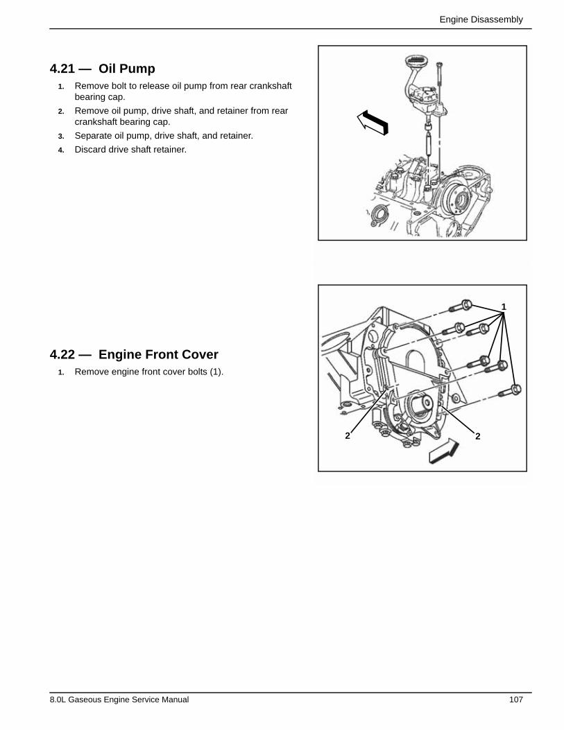
Engine Disassembly
4.21 — Oil Pump1. Remove bolt to release oil pump from rear crankshaft
bearing cap.
2. Remove oil pump, drive shaft, and retainer from rear crankshaft bearing cap.
3. Separate oil pump, drive shaft, and retainer.
4. Discard drive shaft retainer.
4.22 — Engine Front Cover1. Remove engine front cover bolts (1).
2
1
2
8.0L Gaseous Engine Service Manual 107
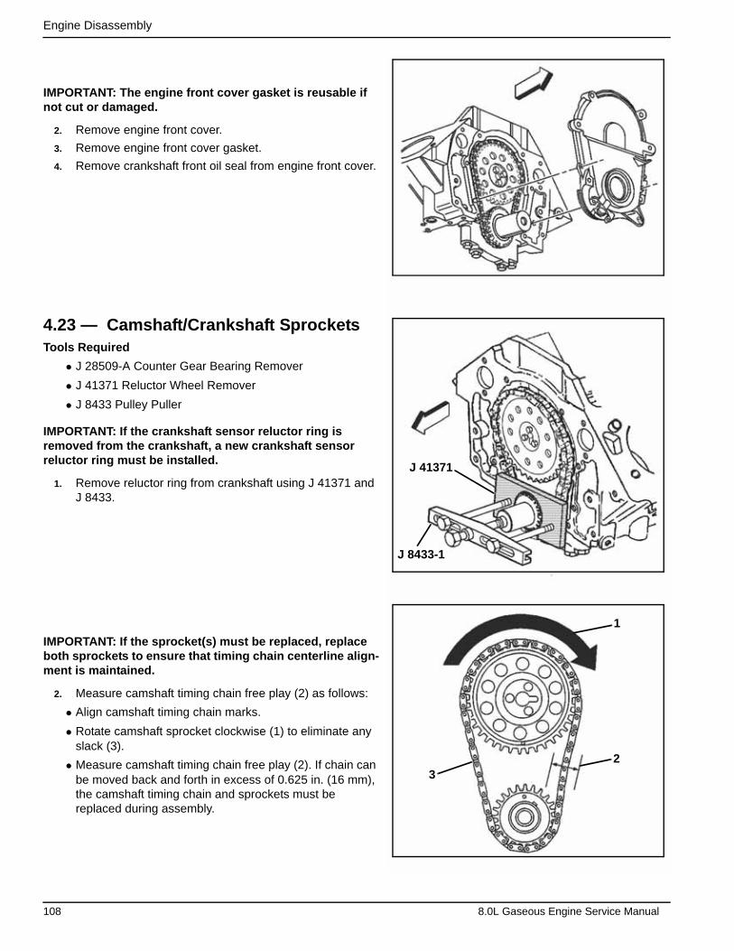
Engine Disassembly
IMPORTANT: The engine front cover gasket is reusable if not cut or damaged.
2. Remove engine front cover.
3. Remove engine front cover gasket.
4. Remove crankshaft front oil seal from engine front cover.
4.23 — Camshaft/Crankshaft SprocketsTools Required
• J 28509-A Counter Gear Bearing Remover
• J 41371 Reluctor Wheel Remover
• J 8433 Pulley Puller
IMPORTANT: If the crankshaft sensor reluctor ring is removed from the crankshaft, a new crankshaft sensor reluctor ring must be installed.
1. Remove reluctor ring from crankshaft using J 41371 and J 8433.
IMPORTANT: If the sprocket(s) must be replaced, replace both sprockets to ensure that timing chain centerline align-ment is maintained.
2. Measure camshaft timing chain free play (2) as follows:
• Align camshaft timing chain marks.
• Rotate camshaft sprocket clockwise (1) to eliminate any slack (3).
• Measure camshaft timing chain free play (2). If chain can be moved back and forth in excess of 0.625 in. (16 mm), the camshaft timing chain and sprockets must be replaced during assembly.
J 8433-1
J 41371
1
23
108 8.0L Gaseous Engine Service Manual
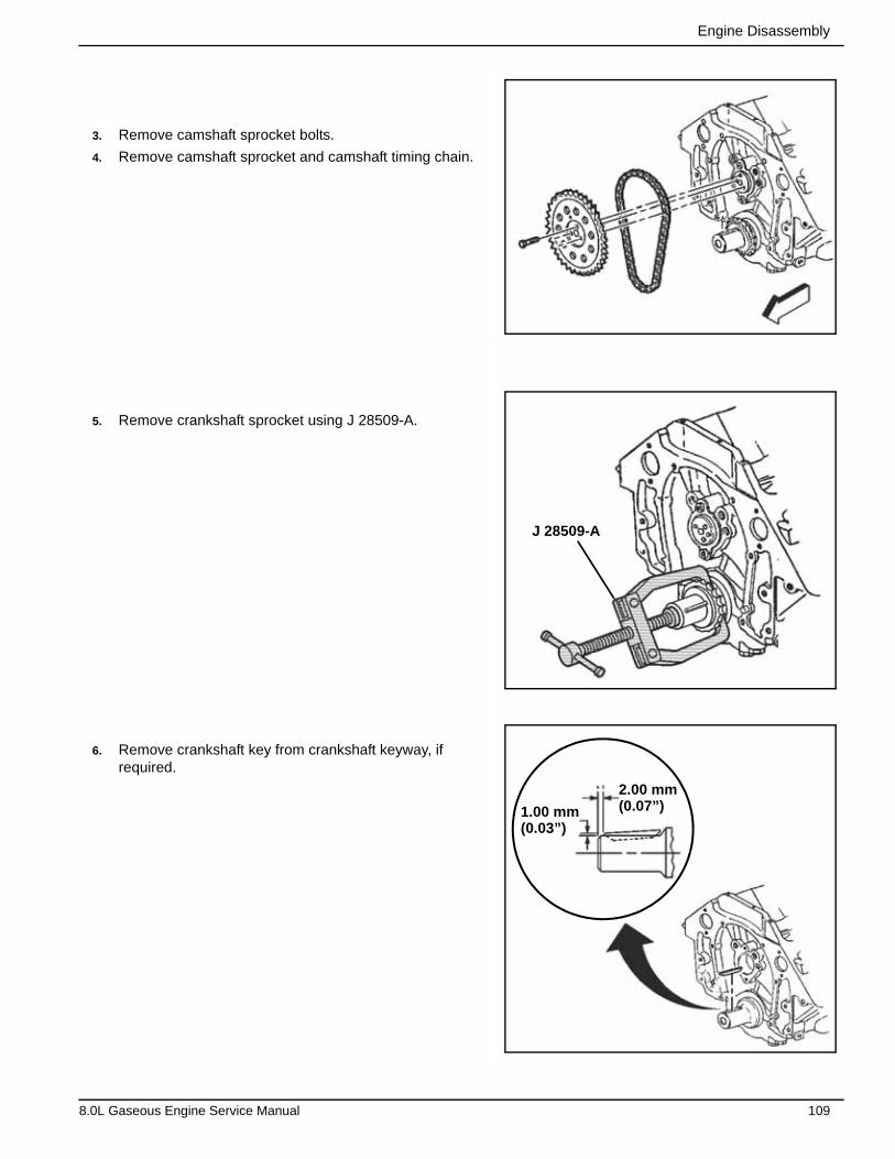
Engine Disassembly
3. Remove camshaft sprocket bolts.
4. Remove camshaft sprocket and camshaft timing chain.
5. Remove crankshaft sprocket using J 28509-A.
6. Remove crankshaft key from crankshaft keyway, if required.
2.00 mm(0.07”)1.00 mm
(0.03”)
J 28509-A
8.0L Gaseous Engine Service Manual 109

Engine Disassembly
4.24 — Camshaft1. Remove camshaft retainer bolts.
2. Remove camshaft retainer.
3. Install three 5/16-18 x 4.0 inch bolts in camshaft front bolt holes.
NOTE: All camshaft journals are the same diameter, so exercise care when removing or installing the camshaft to avoid damage to camshaft bearings.
4. Using bolts as a handle, carefully rotate and pull cam-shaft out of engine block.
5. Remove bolts from front of camshaft.
4.25 — Piston/Connecting RodTools Required
• J 24270 Ridge Reamer
• J 5239 Guide Set
IMPORTANT: Do not remove excessive material from cylin-der bore. Excessive removal of material may require cylin-der boring to the next oversize.
1. Remove cylinder bore ridge as necessary. Proceed as follows:
• Rotate crankshaft until piston is at bottom of stroke (BDC).
• Place a cloth on top of piston.
• Perform cutting operation with a J 24270. Refer to manu-facturer’s instructions before using J24270.
• Remove J 24270.
• Rotate crankshaft until piston is at top dead center (TDC). J 24270
110 8.0L Gaseous Engine Service Manual
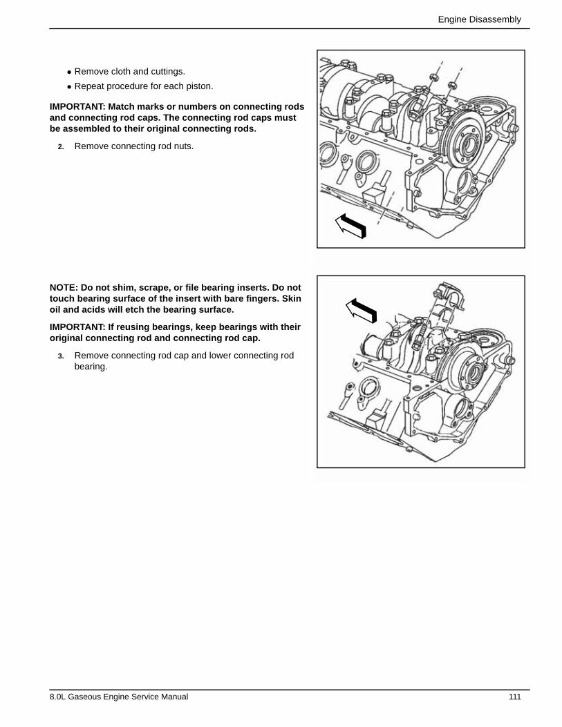
Engine Disassembly
• Remove cloth and cuttings.
• Repeat procedure for each piston.
IMPORTANT: Match marks or numbers on connecting rods and connecting rod caps. The connecting rod caps must be assembled to their original connecting rods.
2. Remove connecting rod nuts.
NOTE: Do not shim, scrape, or file bearing inserts. Do not touch bearing surface of the insert with bare fingers. Skin oil and acids will etch the bearing surface.
IMPORTANT: If reusing bearings, keep bearings with their original connecting rod and connecting rod cap.
3. Remove connecting rod cap and lower connecting rod bearing.
8.0L Gaseous Engine Service Manual 111
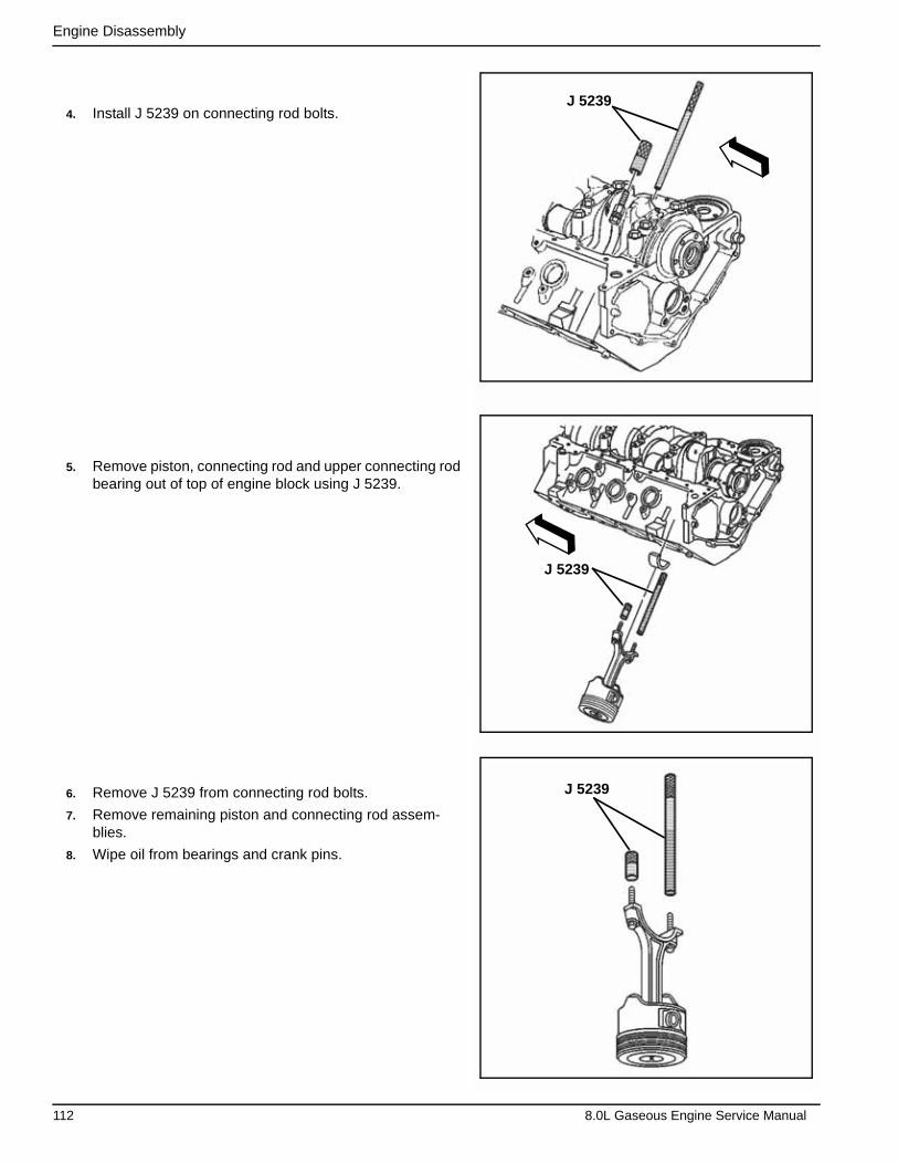
Engine Disassembly
4. Install J 5239 on connecting rod bolts.
5. Remove piston, connecting rod and upper connecting rod bearing out of top of engine block using J 5239.
6. Remove J 5239 from connecting rod bolts.
7. Remove remaining piston and connecting rod assem-blies.
8. Wipe oil from bearings and crank pins.
J 5239
J 5239
J 5239
112 8.0L Gaseous Engine Service Manual
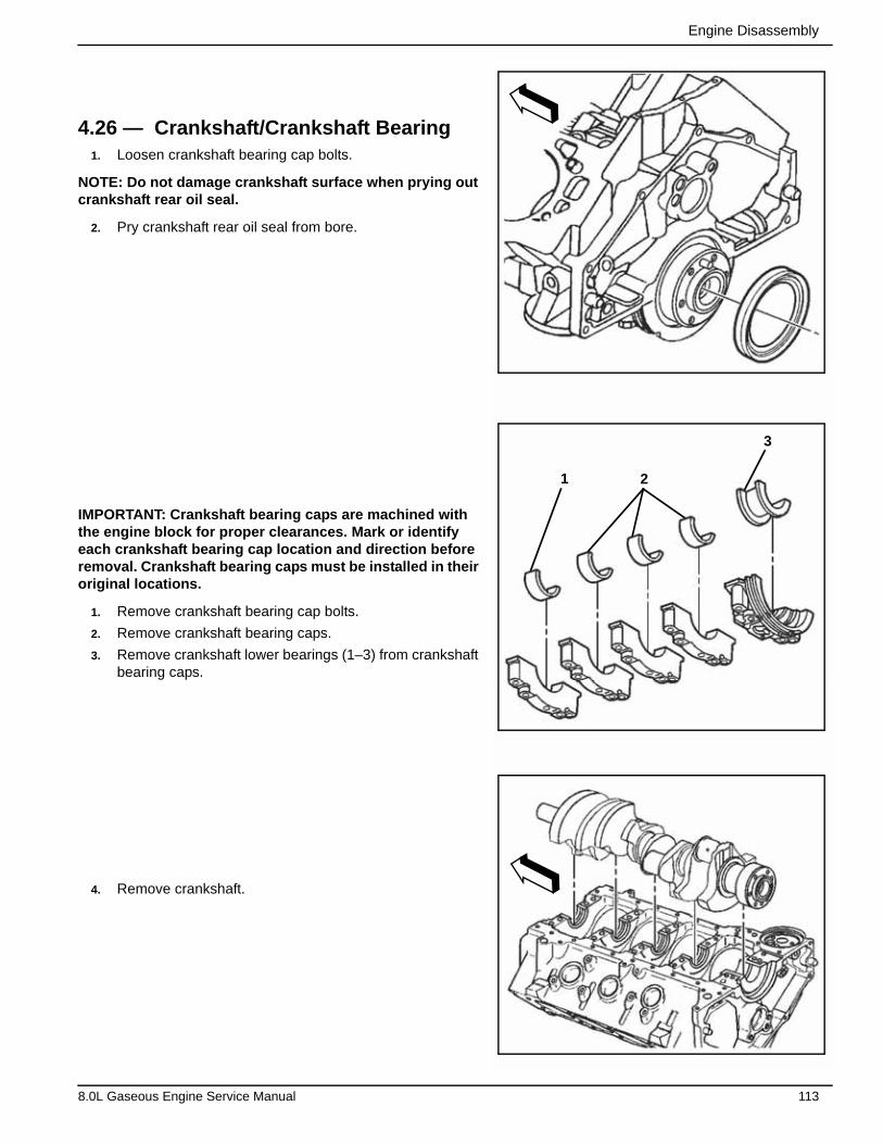
Engine Disassembly
4.26 — Crankshaft/Crankshaft Bearing1. Loosen crankshaft bearing cap bolts.
NOTE: Do not damage crankshaft surface when prying out crankshaft rear oil seal.
2. Pry crankshaft rear oil seal from bore.
IMPORTANT: Crankshaft bearing caps are machined with the engine block for proper clearances. Mark or identify each crankshaft bearing cap location and direction before removal. Crankshaft bearing caps must be installed in their original locations.
1. Remove crankshaft bearing cap bolts.
2. Remove crankshaft bearing caps.
3. Remove crankshaft lower bearings (1–3) from crankshaft bearing caps.
4. Remove crankshaft.
1 2
3
8.0L Gaseous Engine Service Manual 113
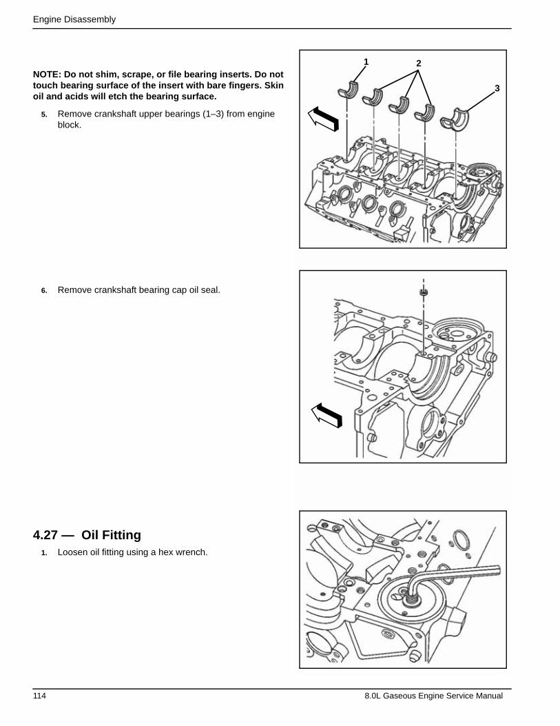
Engine Disassembly
NOTE: Do not shim, scrape, or file bearing inserts. Do not touch bearing surface of the insert with bare fingers. Skin oil and acids will etch the bearing surface.
5. Remove crankshaft upper bearings (1–3) from engine block.
6. Remove crankshaft bearing cap oil seal.
4.27 — Oil Fitting1. Loosen oil fitting using a hex wrench.
21
3
114 8.0L Gaseous Engine Service Manual
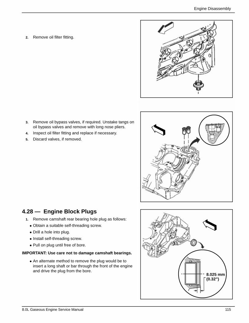
Engine Disassembly
2. Remove oil filter fitting.
3. Remove oil bypass valves, if required. Unstake tangs on oil bypass valves and remove with long nose pliers.
4. Inspect oil filter fitting and replace if necessary.
5. Discard valves, if removed.
4.28 — Engine Block Plugs1. Remove camshaft rear bearing hole plug as follows:
• Obtain a suitable self-threading screw.
• Drill a hole into plug.
• Install self-threading screw.
• Pull on plug until free of bore.
IMPORTANT: Use care not to damage camshaft bearings.
• An alternate method to remove the plug would be to insert a long shaft or bar through the front of the engine and drive the plug from the bore.
8.025 mm(0.32”)
8.0L Gaseous Engine Service Manual 115

Engine Disassembly
2. Remove expansion plugs from both sides of engine block.
• Obtain a suitable self-threading screw.
• Drill a hole into plug.
• Install self-threading screw.
• Pull on plug until free of bore.
3. Remove engine block coolant drain hole plugs.
116 8.0L Gaseous Engine Service Manual
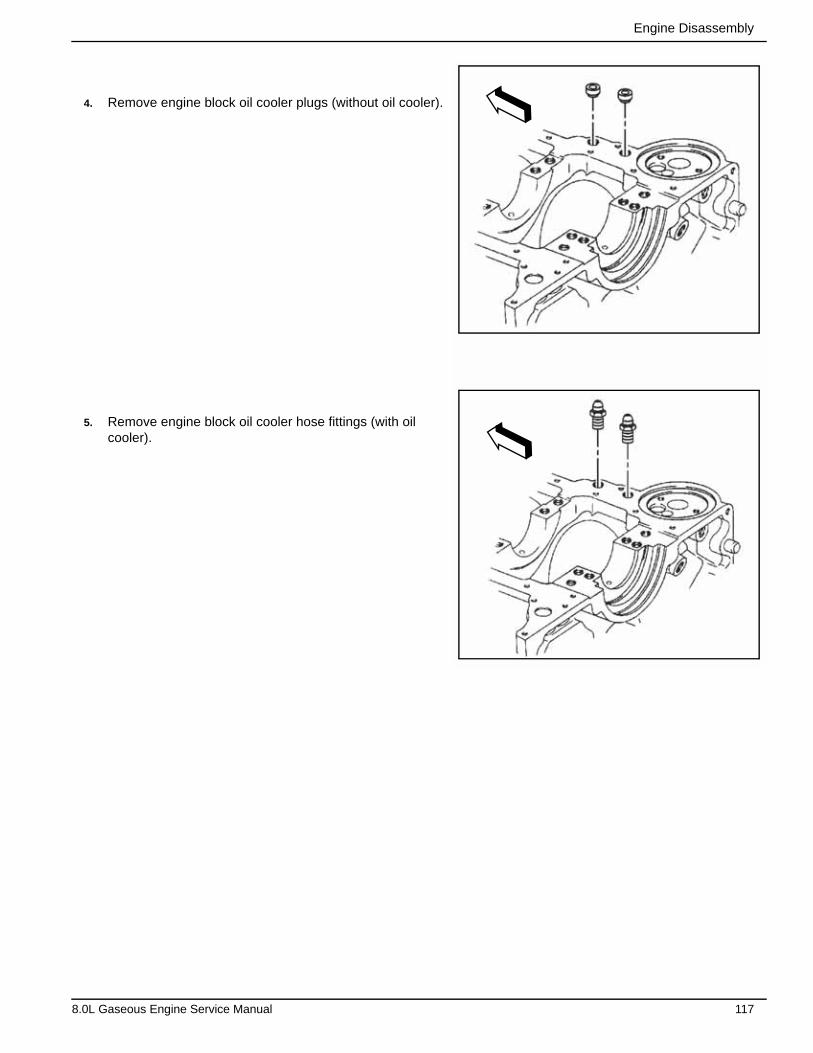
Engine Disassembly
4. Remove engine block oil cooler plugs (without oil cooler).
5. Remove engine block oil cooler hose fittings (with oil cooler).
8.0L Gaseous Engine Service Manual 117
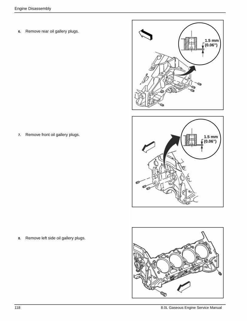
Engine Disassembly
6. Remove rear oil gallery plugs.
7. Remove front oil gallery plugs.
8. Remove left side oil gallery plugs.
1.5 mm(0.06”)
1.5 mm(0.06”)
118 8.0L Gaseous Engine Service Manual

Engine Disassembly
9. Remove top oil gallery plugs.
8.0L Gaseous Engine Service Manual 119
Engine Disassembly
This page intentionally left blank.
120 8.0L Gaseous Engine Service Manual
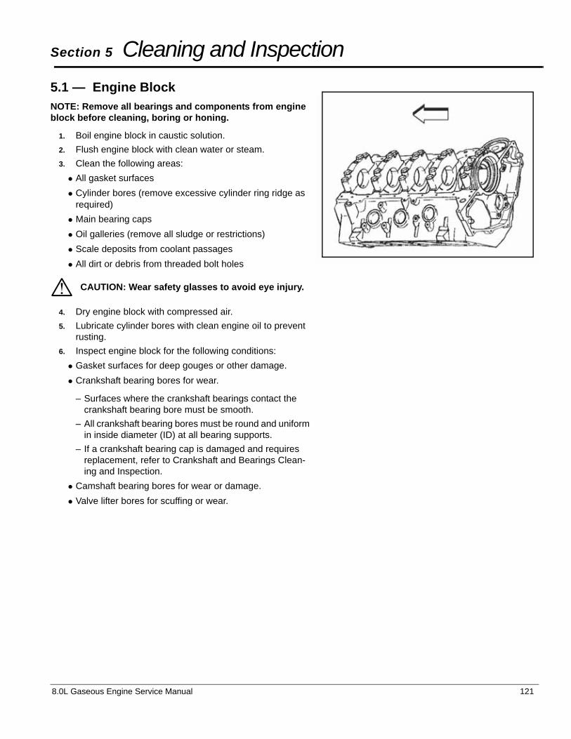
8.0L Gaseous Engine Service Manual 121
Section 5 Cleaning and Inspection
5.1 — Engine BlockNOTE: Remove all bearings and components from engine block before cleaning, boring or honing.
1. Boil engine block in caustic solution.
2. Flush engine block with clean water or steam.
3. Clean the following areas:
• All gasket surfaces
• Cylinder bores (remove excessive cylinder ring ridge as required)
• Main bearing caps
• Oil galleries (remove all sludge or restrictions)
• Scale deposits from coolant passages
• All dirt or debris from threaded bolt holes
4. Dry engine block with compressed air.
5. Lubricate cylinder bores with clean engine oil to prevent rusting.
6. Inspect engine block for the following conditions:
• Gasket surfaces for deep gouges or other damage.
• Crankshaft bearing bores for wear.
– Surfaces where the crankshaft bearings contact the crankshaft bearing bore must be smooth.
– All crankshaft bearing bores must be round and uniform in inside diameter (ID) at all bearing supports.
– If a crankshaft bearing cap is damaged and requires replacement, refer to Crankshaft and Bearings Clean-ing and Inspection.
• Camshaft bearing bores for wear or damage.
• Valve lifter bores for scuffing or wear.
CAUTION: Wear safety glasses to avoid eye injury.*
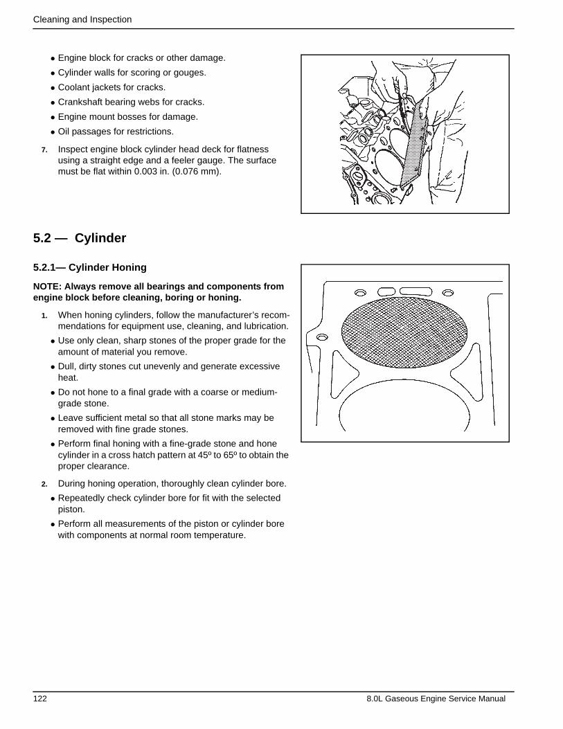
Cleaning and Inspection
• Engine block for cracks or other damage.
• Cylinder walls for scoring or gouges.
• Coolant jackets for cracks.
• Crankshaft bearing webs for cracks.
• Engine mount bosses for damage.
• Oil passages for restrictions.
7. Inspect engine block cylinder head deck for flatness using a straight edge and a feeler gauge. The surface must be flat within 0.003 in. (0.076 mm).
5.2 — Cylinder
5.2.1— Cylinder Honing
NOTE: Always remove all bearings and components from engine block before cleaning, boring or honing.
1. When honing cylinders, follow the manufacturer’s recom-mendations for equipment use, cleaning, and lubrication.
• Use only clean, sharp stones of the proper grade for the amount of material you remove.
• Dull, dirty stones cut unevenly and generate excessive heat.
• Do not hone to a final grade with a coarse or medium-grade stone.
• Leave sufficient metal so that all stone marks may be removed with fine grade stones.
• Perform final honing with a fine-grade stone and hone cylinder in a cross hatch pattern at 45º to 65º to obtain the proper clearance.
2. During honing operation, thoroughly clean cylinder bore.
• Repeatedly check cylinder bore for fit with the selected piston.
• Perform all measurements of the piston or cylinder bore with components at normal room temperature.
122 8.0L Gaseous Engine Service Manual
Cleaning and Inspection
3. When honing to eliminate taper in the cylinder, make full strokes of the hone in the cylinder. Repeatedly check the measurement at the top, middle, and bottom of the bore.
• The finish marks should be clean but not sharp.
• The finish marks should be free from embedded particles and torn or folded metal.
4. By measuring the selected piston at the sizing point and by adding the average of the clearance specification, you can determine the cylinder honing dimension required. See Engine Tolerances and Wear Limits in Section 1.
5. When finished, the reconditioned cylinder bores should have less than or meet the specified out-of-round or taper requirements.
6. After final honing and before the piston is checked for fit, clean bores with hot water and detergent.
• Scrub bores with a stiff bristle brush and rinse thoroughly with hot water. Do not allow any abrasive material to remain in the cylinder bores.
– Abrasive material may cause premature wear of new piston rings and cylinder bores.
– Abrasive material will contaminate engine oil and may cause premature wear of bearings.
• After washing the cylinder bore, dry with a clean shop towel.
7. Perform final measurements of the piston and cylinder bore.
8. Permanently mark the piston for the specific cylinder to which it has been fitted.
9. Apply clean engine oil to each cylinder bore to prevent rusting.
5.2.2— Cylinder Boring
1. Before you start the honing or boring operation, measure all new pistons with the micrometer contacting at points exactly 90º from the piston pin centerline.
IMPORTANT: If you do not check the cylinder block, the boring bar may be tilted, this may result in incorrect rebored cylinder wall to crankshaft angle.
2. Before you use any type of boring bar, file the top of the cylinder block to remove any dirt or burrs.
3. Carefully follow instructions furnished by the manufacturer regarding use of equipment.
4. When you rebore cylinders, make sure all crankshaft bearing caps are in place.
• Tighten bearing caps to the proper torque to avoid distortion of the bores in the final assembly.
• The crankshaft must be clear of the boring cutter when you bore each cylinder.
8.0L Gaseous Engine Service Manual 123
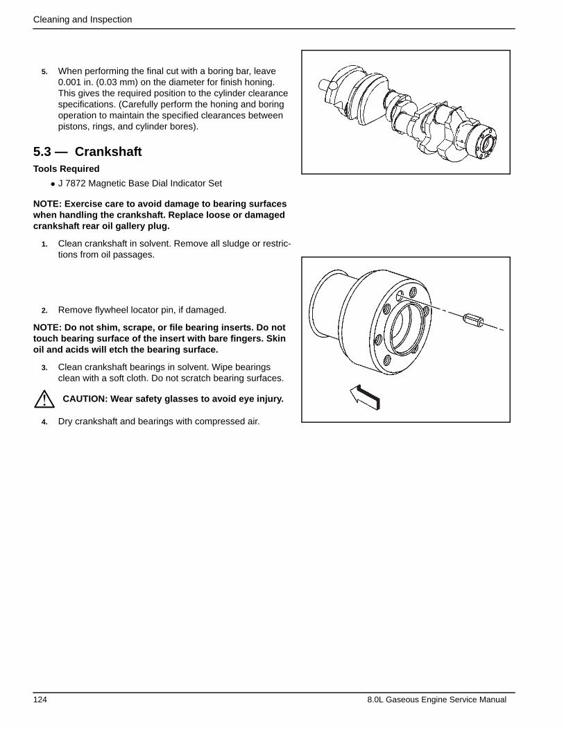
Cleaning and Inspection
5. When performing the final cut with a boring bar, leave 0.001 in. (0.03 mm) on the diameter for finish honing. This gives the required position to the cylinder clearance specifications. (Carefully perform the honing and boring operation to maintain the specified clearances between pistons, rings, and cylinder bores).
5.3 — CrankshaftTools Required
• J 7872 Magnetic Base Dial Indicator Set
NOTE: Exercise care to avoid damage to bearing surfaces when handling the crankshaft. Replace loose or damaged crankshaft rear oil gallery plug.
1. Clean crankshaft in solvent. Remove all sludge or restric-tions from oil passages.
2. Remove flywheel locator pin, if damaged.
NOTE: Do not shim, scrape, or file bearing inserts. Do not touch bearing surface of the insert with bare fingers. Skin oil and acids will etch the bearing surface.
3. Clean crankshaft bearings in solvent. Wipe bearings clean with a soft cloth. Do not scratch bearing surfaces.
4. Dry crankshaft and bearings with compressed air.
CAUTION: Wear safety glasses to avoid eye injury.*
124 8.0L Gaseous Engine Service Manual
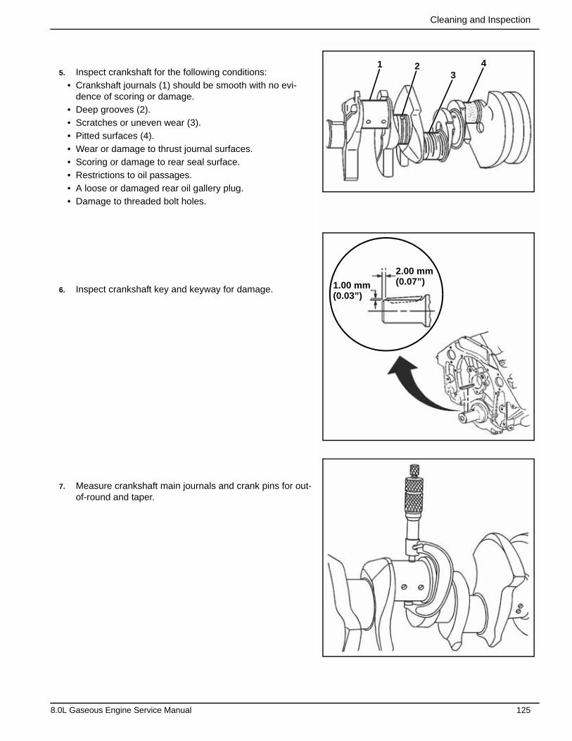
Cleaning and Inspection
5. Inspect crankshaft for the following conditions:
• Crankshaft journals (1) should be smooth with no evi-dence of scoring or damage.
• Deep grooves (2).
• Scratches or uneven wear (3).
• Pitted surfaces (4).
• Wear or damage to thrust journal surfaces.
• Scoring or damage to rear seal surface.
• Restrictions to oil passages.
• A loose or damaged rear oil gallery plug.
• Damage to threaded bolt holes.
6. Inspect crankshaft key and keyway for damage.
7. Measure crankshaft main journals and crank pins for out-of-round and taper.
1 23
4
2.00 mm(0.07”)1.00 mm
(0.03”)
8.0L Gaseous Engine Service Manual 125
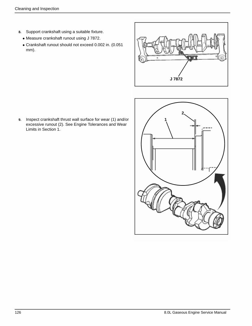
Cleaning and Inspection
8. Support crankshaft using a suitable fixture.
• Measure crankshaft runout using J 7872.
• Crankshaft runout should not exceed 0.002 in. (0.051 mm).
9. Inspect crankshaft thrust wall surface for wear (1) and/or excessive runout (2). See Engine Tolerances and Wear Limits in Section 1.
J 7872
1
2
126 8.0L Gaseous Engine Service Manual
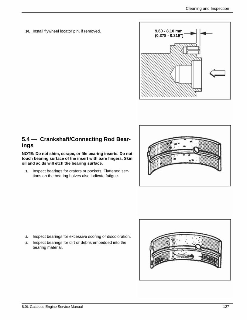
Cleaning and Inspection
10. Install flywheel locator pin, if removed.
5.4 — Crankshaft/Connecting Rod Bear-ingsNOTE: Do not shim, scrape, or file bearing inserts. Do not touch bearing surface of the insert with bare fingers. Skin oil and acids will etch the bearing surface.
1. Inspect bearings for craters or pockets. Flattened sec-tions on the bearing halves also indicate fatigue.
2. Inspect bearings for excessive scoring or discoloration.
3. Inspect bearings for dirt or debris embedded into the bearing material.
9.60 - 8.10 mm(0.378 - 0.319”)
8.0L Gaseous Engine Service Manual 127
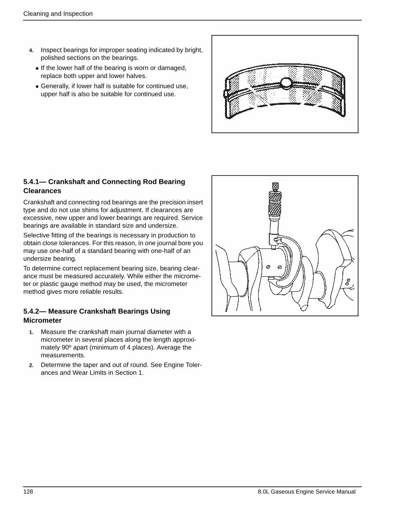
Cleaning and Inspection
4. Inspect bearings for improper seating indicated by bright, polished sections on the bearings.
• If the lower half of the bearing is worn or damaged, replace both upper and lower halves.
• Generally, if lower half is suitable for continued use, upper half is also be suitable for continued use.
5.4.1— Crankshaft and Connecting Rod Bearing Clearances
Crankshaft and connecting rod bearings are the precision insert type and do not use shims for adjustment. If clearances are excessive, new upper and lower bearings are required. Service bearings are available in standard size and undersize.
Selective fitting of the bearings is necessary in production to obtain close tolerances. For this reason, in one journal bore you may use one-half of a standard bearing with one-half of an undersize bearing.
To determine correct replacement bearing size, bearing clear-ance must be measured accurately. While either the microme-ter or plastic gauge method may be used, the micrometer method gives more reliable results.
5.4.2— Measure Crankshaft Bearings Using Micrometer
1. Measure the crankshaft main journal diameter with a micrometer in several places along the length approxi-mately 90º apart (minimum of 4 places). Average the measurements.
2. Determine the taper and out of round. See Engine Toler-ances and Wear Limits in Section 1.
128 8.0L Gaseous Engine Service Manual

Cleaning and Inspection
NOTE: Do not shim, scrape, or file bearing inserts. Do not touch bearing surface of the insert with bare fingers. Skin oil and acids will etch the bearing surface.
3. Install crankshaft bearings into crankshaft bearing caps and engine block.
IMPORTANT: Tighten inner crankshaft bearing cap bolts before tightening outer crankshaft bearing cap bolts.
4. Install crankshaft bearing caps and crankshaft bearing cap bolts as follows:
• Tighten crankshaft bearing cap inner bolts to 102 ft-lbs (138 N-m).
• Tighten crankshaft bearing cap outer bolts to 102 ft-lbs (138 N-m).
5. Measure crankshaft bearing inside diameter (ID) using an inside micrometer. Measure at a minimum of four places and average the measurements.
6. To determine the crankshaft bearing clearance, subtract crankshaft journal diameter from crankshaft bearing ID.
7. Compare crankshaft bearing clearance to specifications. See Engine Tolerances and Wear Limits in Section 1.
8. If crankshaft bearing clearances exceed specifications, install new crankshaft bearings.
9. Measure the new crankshaft bearing inside diameter (ID) using an inside micrometer.
10. Replace or repair crankshaft if proper clearances cannot be obtained.
5.4.3— Measure Connecting Rod Bearings Using Micrometer
1. Measure crank pin diameter with a micrometer in several places along the length, approximately 90º apart (mini-mum of 4 places). Average the measurements.
2. Determine the taper and out-of-round. See Engine Toler-ances and Wear Limits in Section 1.
NOTE: Do not shim, scrape, or file bearing inserts. Do not touch bearing surface of the insert with bare fingers. Skin oil and acids will etch the bearing surface.
3. Install connecting rod bearings into connecting rod cap and connecting rod.
8.0L Gaseous Engine Service Manual 129
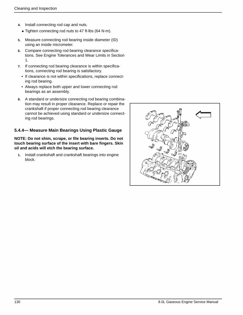
Cleaning and Inspection
4. Install connecting rod cap and nuts.
• Tighten connecting rod nuts to 47 ft-lbs (64 N-m).
5. Measure connecting rod bearing inside diameter (ID) using an inside micrometer.
6. Compare connecting rod bearing clearance specifica-tions. See Engine Tolerances and Wear Limits in Section 1.
7. If connecting rod bearing clearance is within specifica-tions, connecting rod bearing is satisfactory.
• If clearance is not within specifications, replace connect-ing rod bearing.
• Always replace both upper and lower connecting rod bearings as an assembly.
8. A standard or undersize connecting rod bearing combina-tion may result in proper clearance. Replace or repair the crankshaft if proper connecting rod bearing clearance cannot be achieved using standard or undersize connect-ing rod bearings.
5.4.4— Measure Main Bearings Using Plastic Gauge
NOTE: Do not shim, scrape, or file bearing inserts. Do not touch bearing surface of the insert with bare fingers. Skin oil and acids will etch the bearing surface.
1. Install crankshaft and crankshaft bearings into engine block.
130 8.0L Gaseous Engine Service Manual
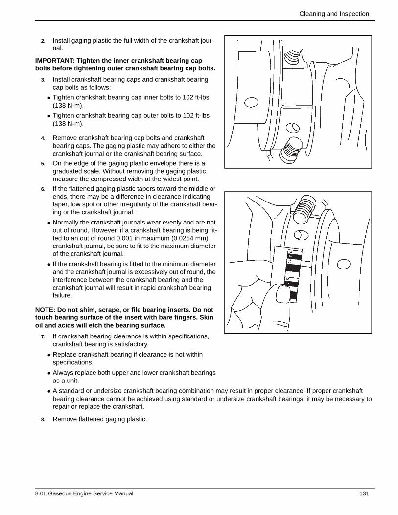
Cleaning and Inspection
2. Install gaging plastic the full width of the crankshaft jour-nal.
IMPORTANT: Tighten the inner crankshaft bearing cap bolts before tightening outer crankshaft bearing cap bolts.
3. Install crankshaft bearing caps and crankshaft bearing cap bolts as follows:
• Tighten crankshaft bearing cap inner bolts to 102 ft-lbs (138 N-m).
• Tighten crankshaft bearing cap outer bolts to 102 ft-lbs (138 N-m).
4. Remove crankshaft bearing cap bolts and crankshaft bearing caps. The gaging plastic may adhere to either the crankshaft journal or the crankshaft bearing surface.
5. On the edge of the gaging plastic envelope there is a graduated scale. Without removing the gaging plastic, measure the compressed width at the widest point.
6. If the flattened gaging plastic tapers toward the middle or ends, there may be a difference in clearance indicating taper, low spot or other irregularity of the crankshaft bear-ing or the crankshaft journal.
• Normally the crankshaft journals wear evenly and are not out of round. However, if a crankshaft bearing is being fit-ted to an out of round 0.001 in maximum (0.0254 mm) crankshaft journal, be sure to fit to the maximum diameter of the crankshaft journal.
• If the crankshaft bearing is fitted to the minimum diameter and the crankshaft journal is excessively out of round, the interference between the crankshaft bearing and the crankshaft journal will result in rapid crankshaft bearing failure.
NOTE: Do not shim, scrape, or file bearing inserts. Do not touch bearing surface of the insert with bare fingers. Skin oil and acids will etch the bearing surface.
7. If crankshaft bearing clearance is within specifications, crankshaft bearing is satisfactory.
• Replace crankshaft bearing if clearance is not within specifications.
• Always replace both upper and lower crankshaft bearings as a unit.
• A standard or undersize crankshaft bearing combination may result in proper clearance. If proper crankshaft bearing clearance cannot be achieved using standard or undersize crankshaft bearings, it may be necessary to repair or replace the crankshaft.
8. Remove flattened gaging plastic.
8.0L Gaseous Engine Service Manual 131

Cleaning and Inspection
9. Measure remaining crankshaft journals.
5.4.5— Measure Connecting Rod Bearings Using Plastic Gauge
NOTE: Do not shim, scrape, or file bearing inserts. Do not touch bearing surface of the insert with bare fingers. Skin oil and acids will etch the bearing surface.
1. Install connecting rod bearings into connecting rod and connecting rod cap.
2. Install piston and connecting rod assembly onto crank pin journal.
3. Install gaging plastic the full width of the crank pin journal.
132 8.0L Gaseous Engine Service Manual
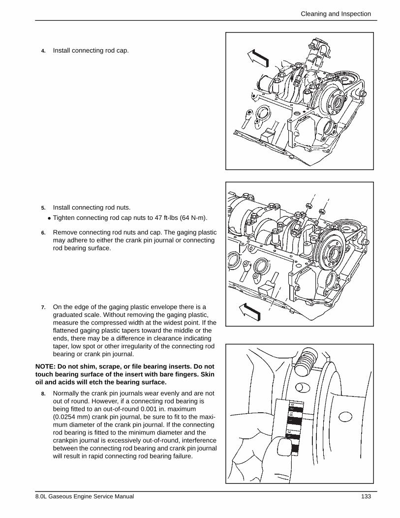
Cleaning and Inspection
4. Install connecting rod cap.
5. Install connecting rod nuts.
• Tighten connecting rod cap nuts to 47 ft-lbs (64 N-m).
6. Remove connecting rod nuts and cap. The gaging plastic may adhere to either the crank pin journal or connecting rod bearing surface.
7. On the edge of the gaging plastic envelope there is a graduated scale. Without removing the gaging plastic, measure the compressed width at the widest point. If the flattened gaging plastic tapers toward the middle or the ends, there may be a difference in clearance indicating taper, low spot or other irregularity of the connecting rod bearing or crank pin journal.
NOTE: Do not shim, scrape, or file bearing inserts. Do not touch bearing surface of the insert with bare fingers. Skin oil and acids will etch the bearing surface.
8. Normally the crank pin journals wear evenly and are not out of round. However, if a connecting rod bearing is being fitted to an out-of-round 0.001 in. maximum (0.0254 mm) crank pin journal, be sure to fit to the maxi-mum diameter of the crank pin journal. If the connecting rod bearing is fitted to the minimum diameter and the crankpin journal is excessively out-of-round, interference between the connecting rod bearing and crank pin journal will result in rapid connecting rod bearing failure.
8.0L Gaseous Engine Service Manual 133
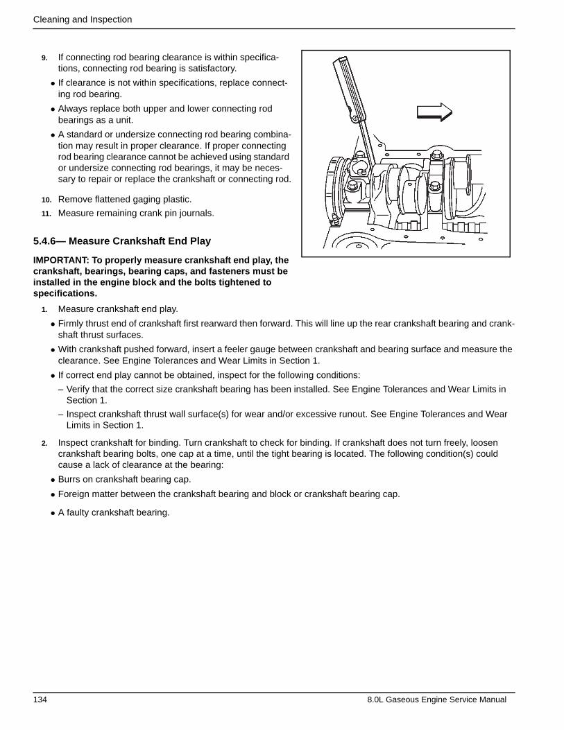
Cleaning and Inspection
9. If connecting rod bearing clearance is within specifica-tions, connecting rod bearing is satisfactory.
• If clearance is not within specifications, replace connect-ing rod bearing.
• Always replace both upper and lower connecting rod bearings as a unit.
• A standard or undersize connecting rod bearing combina-tion may result in proper clearance. If proper connecting rod bearing clearance cannot be achieved using standard or undersize connecting rod bearings, it may be neces-sary to repair or replace the crankshaft or connecting rod.
10. Remove flattened gaging plastic.
11. Measure remaining crank pin journals.
5.4.6— Measure Crankshaft End Play
IMPORTANT: To properly measure crankshaft end play, the crankshaft, bearings, bearing caps, and fasteners must be installed in the engine block and the bolts tightened to specifications.
1. Measure crankshaft end play.
• Firmly thrust end of crankshaft first rearward then forward. This will line up the rear crankshaft bearing and crank-shaft thrust surfaces.
• With crankshaft pushed forward, insert a feeler gauge between crankshaft and bearing surface and measure the clearance. See Engine Tolerances and Wear Limits in Section 1.
• If correct end play cannot be obtained, inspect for the following conditions:
– Verify that the correct size crankshaft bearing has been installed. See Engine Tolerances and Wear Limits in Section 1.
– Inspect crankshaft thrust wall surface(s) for wear and/or excessive runout. See Engine Tolerances and Wear Limits in Section 1.
2. Inspect crankshaft for binding. Turn crankshaft to check for binding. If crankshaft does not turn freely, loosen crankshaft bearing bolts, one cap at a time, until the tight bearing is located. The following condition(s) could cause a lack of clearance at the bearing:
• Burrs on crankshaft bearing cap.
• Foreign matter between the crankshaft bearing and block or crankshaft bearing cap.
• A faulty crankshaft bearing.
134 8.0L Gaseous Engine Service Manual
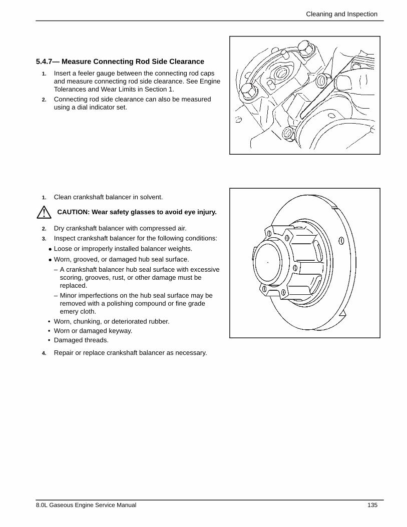
Cleaning and Inspection
5.4.7— Measure Connecting Rod Side Clearance
1. Insert a feeler gauge between the connecting rod caps and measure connecting rod side clearance. See Engine Tolerances and Wear Limits in Section 1.
2. Connecting rod side clearance can also be measured using a dial indicator set.
1. Clean crankshaft balancer in solvent.
2. Dry crankshaft balancer with compressed air.
3. Inspect crankshaft balancer for the following conditions:
• Loose or improperly installed balancer weights.
• Worn, grooved, or damaged hub seal surface.
– A crankshaft balancer hub seal surface with excessive scoring, grooves, rust, or other damage must be replaced.
– Minor imperfections on the hub seal surface may be removed with a polishing compound or fine grade emery cloth.
• Worn, chunking, or deteriorated rubber.
• Worn or damaged keyway.
• Damaged threads.
4. Repair or replace crankshaft balancer as necessary.
CAUTION: Wear safety glasses to avoid eye injury.*
8.0L Gaseous Engine Service Manual 135
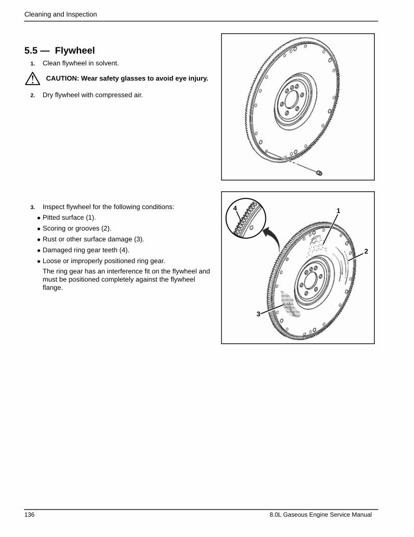
Cleaning and Inspection
5.5 — Flywheel1. Clean flywheel in solvent.
2. Dry flywheel with compressed air.
3. Inspect flywheel for the following conditions:
• Pitted surface (1).
• Scoring or grooves (2).
• Rust or other surface damage (3).
• Damaged ring gear teeth (4).
• Loose or improperly positioned ring gear.
The ring gear has an interference fit on the flywheel and must be positioned completely against the flywheel flange.
CAUTION: Wear safety glasses to avoid eye injury.
4 1
2
3
*
136 8.0L Gaseous Engine Service Manual
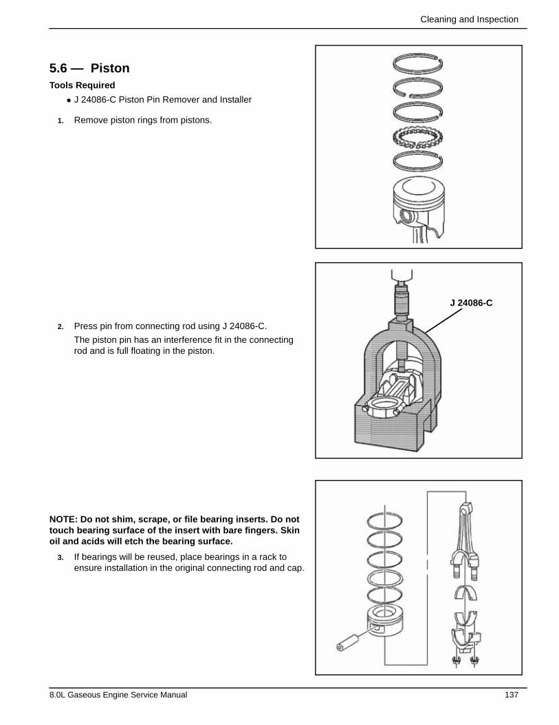
Cleaning and Inspection
5.6 — PistonTools Required
• J 24086-C Piston Pin Remover and Installer
1. Remove piston rings from pistons.
2. Press pin from connecting rod using J 24086-C.
The piston pin has an interference fit in the connecting rod and is full floating in the piston.
NOTE: Do not shim, scrape, or file bearing inserts. Do not touch bearing surface of the insert with bare fingers. Skin oil and acids will etch the bearing surface.
3. If bearings will be reused, place bearings in a rack to ensure installation in the original connecting rod and cap.
J 24086-C
8.0L Gaseous Engine Service Manual 137
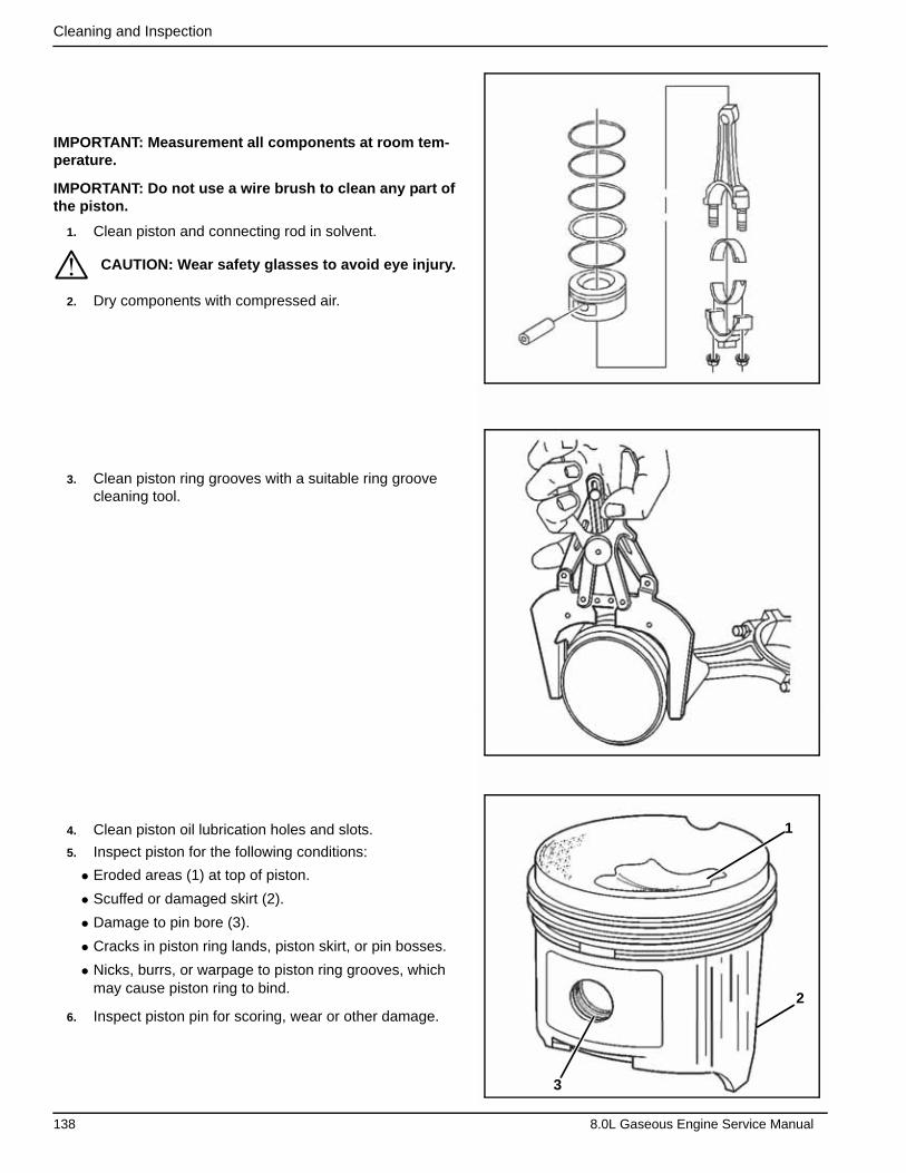
Cleaning and Inspection
IMPORTANT: Measurement all components at room tem-perature.
IMPORTANT: Do not use a wire brush to clean any part of the piston.
1. Clean piston and connecting rod in solvent.
2. Dry components with compressed air.
3. Clean piston ring grooves with a suitable ring groove cleaning tool.
4. Clean piston oil lubrication holes and slots.
5. Inspect piston for the following conditions:
• Eroded areas (1) at top of piston.
• Scuffed or damaged skirt (2).
• Damage to pin bore (3).
• Cracks in piston ring lands, piston skirt, or pin bosses.
• Nicks, burrs, or warpage to piston ring grooves, which may cause piston ring to bind.
6. Inspect piston pin for scoring, wear or other damage.
CAUTION: Wear safety glasses to avoid eye injury.
2
1
3
*
138 8.0L Gaseous Engine Service Manual
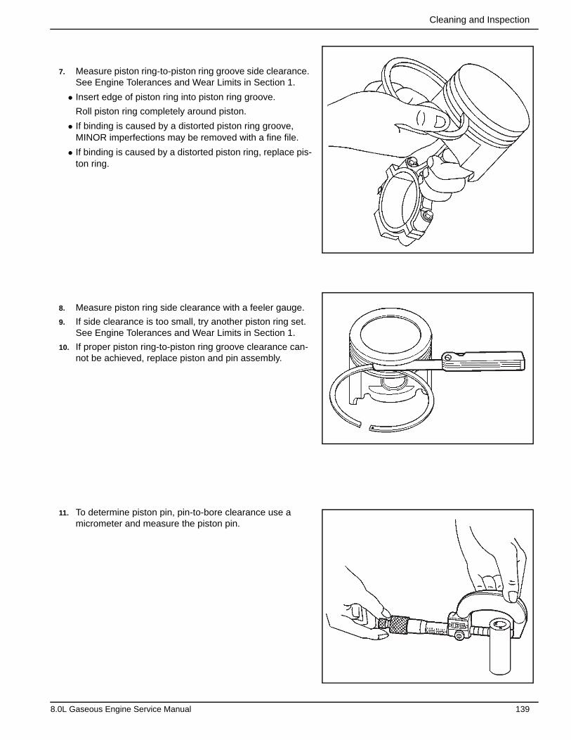
Cleaning and Inspection
7. Measure piston ring-to-piston ring groove side clearance. See Engine Tolerances and Wear Limits in Section 1.
• Insert edge of piston ring into piston ring groove.
Roll piston ring completely around piston.
• If binding is caused by a distorted piston ring groove, MINOR imperfections may be removed with a fine file.
• If binding is caused by a distorted piston ring, replace pis-ton ring.
8. Measure piston ring side clearance with a feeler gauge.
9. If side clearance is too small, try another piston ring set. See Engine Tolerances and Wear Limits in Section 1.
10. If proper piston ring-to-piston ring groove clearance can-not be achieved, replace piston and pin assembly.
11. To determine piston pin, pin-to-bore clearance use a micrometer and measure the piston pin.
8.0L Gaseous Engine Service Manual 139
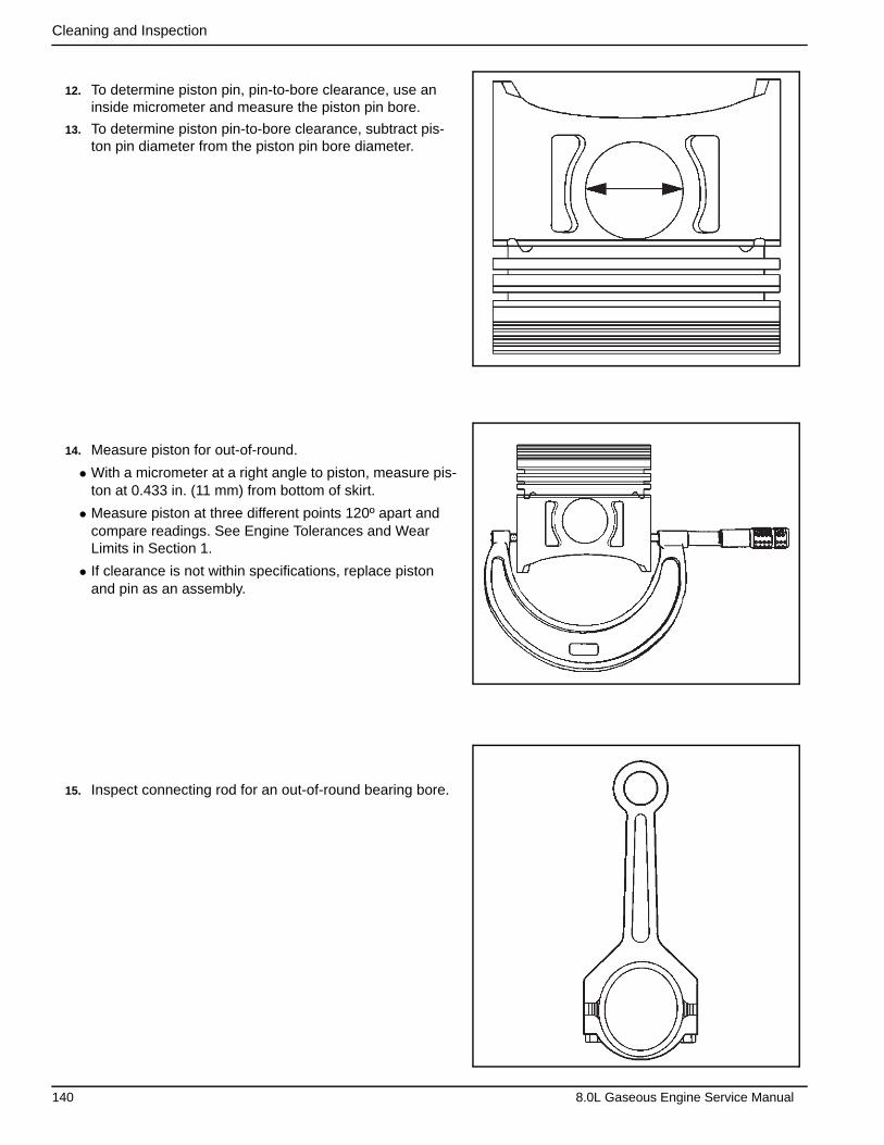
Cleaning and Inspection
12. To determine piston pin, pin-to-bore clearance, use an inside micrometer and measure the piston pin bore.
13. To determine piston pin-to-bore clearance, subtract pis-ton pin diameter from the piston pin bore diameter.
14. Measure piston for out-of-round.
• With a micrometer at a right angle to piston, measure pis-ton at 0.433 in. (11 mm) from bottom of skirt.
• Measure piston at three different points 120º apart and compare readings. See Engine Tolerances and Wear Limits in Section 1.
• If clearance is not within specifications, replace piston and pin as an assembly.
15. Inspect connecting rod for an out-of-round bearing bore.
140 8.0L Gaseous Engine Service Manual
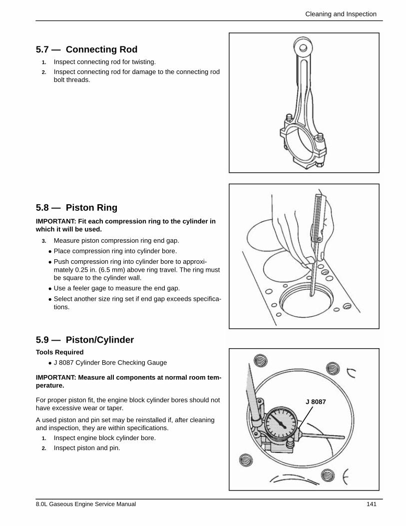
Cleaning and Inspection
5.7 — Connecting Rod1. Inspect connecting rod for twisting.
2. Inspect connecting rod for damage to the connecting rod bolt threads.
5.8 — Piston RingIMPORTANT: Fit each compression ring to the cylinder in which it will be used.
3. Measure piston compression ring end gap.
• Place compression ring into cylinder bore.
• Push compression ring into cylinder bore to approxi-mately 0.25 in. (6.5 mm) above ring travel. The ring must be square to the cylinder wall.
• Use a feeler gage to measure the end gap.
• Select another size ring set if end gap exceeds specifica-tions.
5.9 — Piston/CylinderTools Required
• J 8087 Cylinder Bore Checking Gauge
IMPORTANT: Measure all components at normal room tem-perature.
For proper piston fit, the engine block cylinder bores should not have excessive wear or taper.
A used piston and pin set may be reinstalled if, after cleaning and inspection, they are within specifications.
1. Inspect engine block cylinder bore.
2. Inspect piston and pin.
J 8087
8.0L Gaseous Engine Service Manual 141
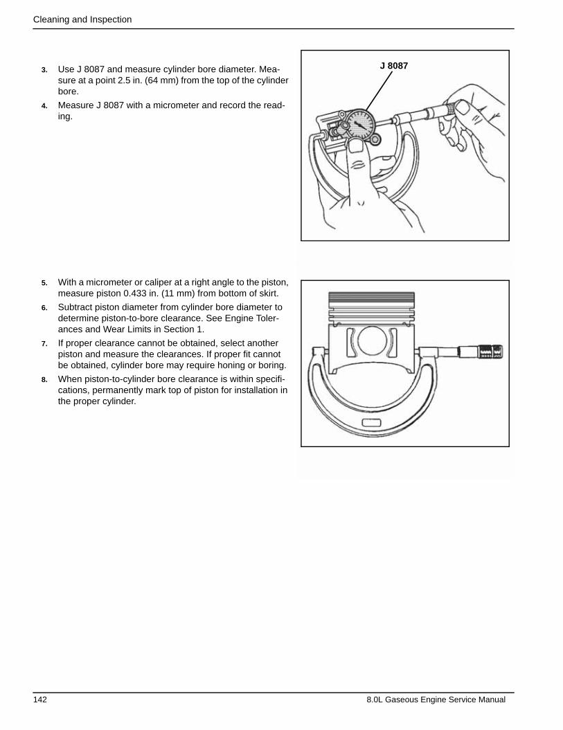
Cleaning and Inspection
3. Use J 8087 and measure cylinder bore diameter. Mea-sure at a point 2.5 in. (64 mm) from the top of the cylinder bore.
4. Measure J 8087 with a micrometer and record the read-ing.
5. With a micrometer or caliper at a right angle to the piston, measure piston 0.433 in. (11 mm) from bottom of skirt.
6. Subtract piston diameter from cylinder bore diameter to determine piston-to-bore clearance. See Engine Toler-ances and Wear Limits in Section 1.
7. If proper clearance cannot be obtained, select another piston and measure the clearances. If proper fit cannot be obtained, cylinder bore may require honing or boring.
8. When piston-to-cylinder bore clearance is within specifi-cations, permanently mark top of piston for installation in the proper cylinder.
J 8087
142 8.0L Gaseous Engine Service Manual
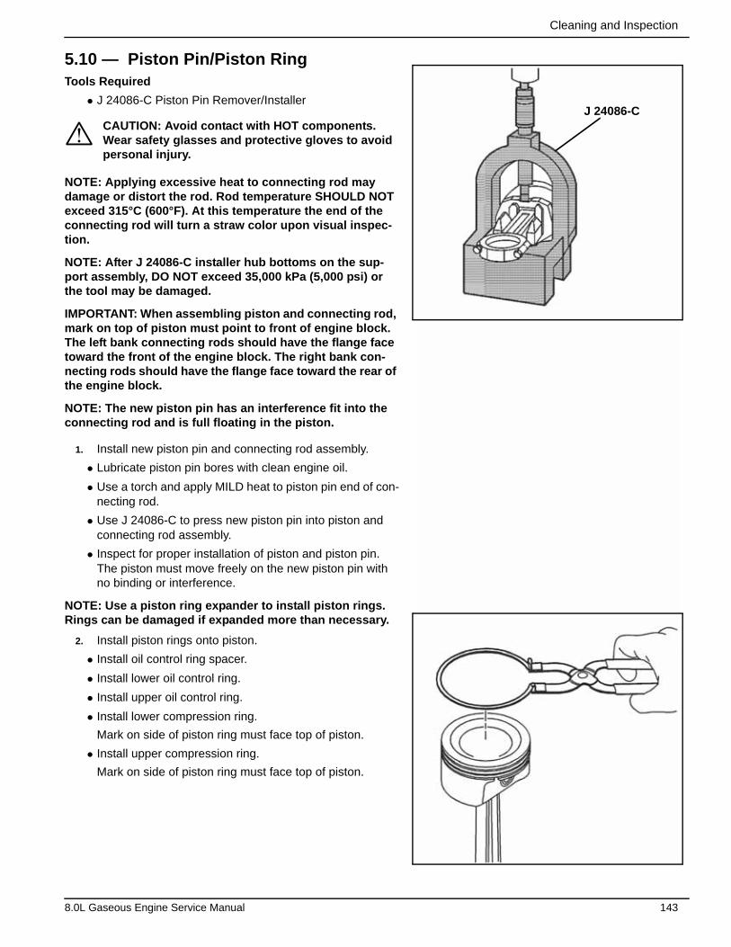
Cleaning and Inspection
5.10 — Piston Pin/Piston Ring Tools Required
• J 24086-C Piston Pin Remover/Installer
NOTE: Applying excessive heat to connecting rod may damage or distort the rod. Rod temperature SHOULD NOT exceed 315°C (600°F). At this temperature the end of the connecting rod will turn a straw color upon visual inspec-tion.
NOTE: After J 24086-C installer hub bottoms on the sup-port assembly, DO NOT exceed 35,000 kPa (5,000 psi) or the tool may be damaged.
IMPORTANT: When assembling piston and connecting rod, mark on top of piston must point to front of engine block. The left bank connecting rods should have the flange face toward the front of the engine block. The right bank con-necting rods should have the flange face toward the rear of the engine block.
NOTE: The new piston pin has an interference fit into the connecting rod and is full floating in the piston.
1. Install new piston pin and connecting rod assembly.
• Lubricate piston pin bores with clean engine oil.
• Use a torch and apply MILD heat to piston pin end of con-necting rod.
• Use J 24086-C to press new piston pin into piston and connecting rod assembly.
• Inspect for proper installation of piston and piston pin. The piston must move freely on the new piston pin with no binding or interference.
NOTE: Use a piston ring expander to install piston rings. Rings can be damaged if expanded more than necessary.
2. Install piston rings onto piston.
• Install oil control ring spacer.
• Install lower oil control ring.
• Install upper oil control ring.
• Install lower compression ring.
Mark on side of piston ring must face top of piston.
• Install upper compression ring.
Mark on side of piston ring must face top of piston.
CAUTION: Avoid contact with HOT components. Wear safety glasses and protective gloves to avoid personal injury.
J 24086-C
*
8.0L Gaseous Engine Service Manual 143

Cleaning and Inspection
3. Space compression ring end gaps 120º apart.
4. Space oil control ring end gaps a minimum of 90º apart.
5.11 — Camshaft Bearing Tools Required
• J 33049 Camshaft Bearing Remover/Installer
1. Remove rear camshaft plug.
Insert a long bar through front of engine and drive plug out of rear bore.
IMPORTANT: A loose camshaft bearing may be caused by an enlarged, out-of-round, or damaged engine block bear-ing bore.
2. Before bearing removal, inspect camshaft bearings for loose fit in engine block bearing bores (positions 1–5).
8.025 mm(0.32”)
5
4
3
2
1
144 8.0L Gaseous Engine Service Manual
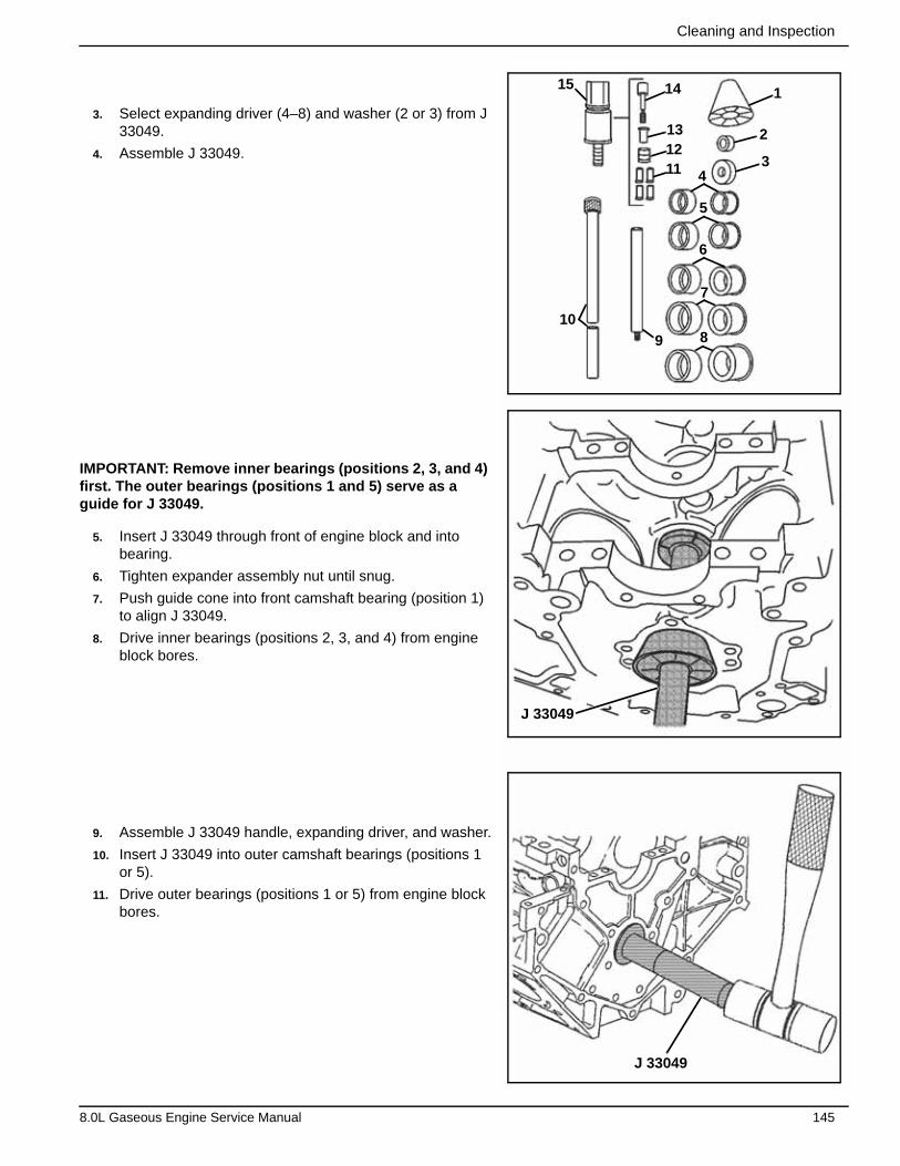
Cleaning and Inspection
3. Select expanding driver (4–8) and washer (2 or 3) from J 33049.
4. Assemble J 33049.
IMPORTANT: Remove inner bearings (positions 2, 3, and 4) first. The outer bearings (positions 1 and 5) serve as a guide for J 33049.
5. Insert J 33049 through front of engine block and into bearing.
6. Tighten expander assembly nut until snug.
7. Push guide cone into front camshaft bearing (position 1) to align J 33049.
8. Drive inner bearings (positions 2, 3, and 4) from engine block bores.
9. Assemble J 33049 handle, expanding driver, and washer.
10. Insert J 33049 into outer camshaft bearings (positions 1 or 5).
11. Drive outer bearings (positions 1 or 5) from engine block bores.
J 33049
J 33049
151
2
34
5
6
7
89
10
111213
14
8.0L Gaseous Engine Service Manual 145
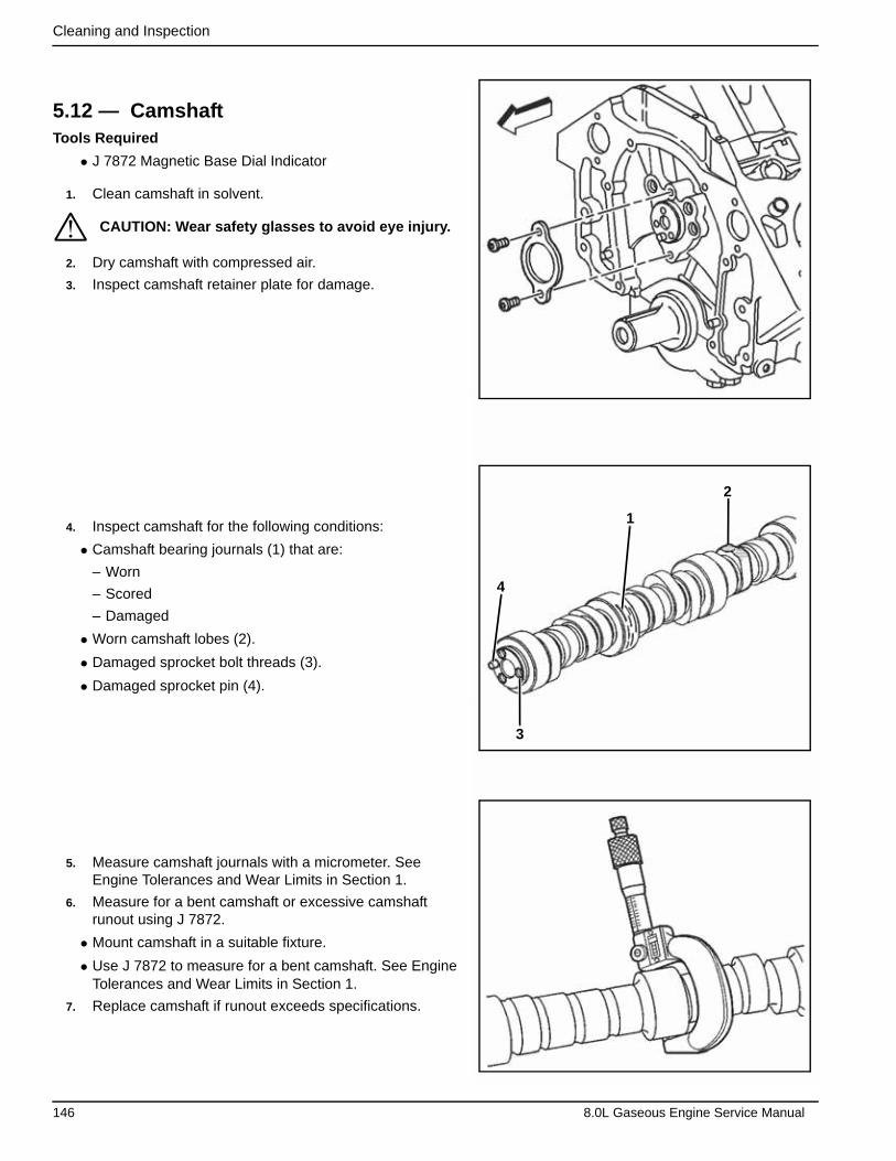
Cleaning and Inspection
5.12 — CamshaftTools Required
• J 7872 Magnetic Base Dial Indicator
1. Clean camshaft in solvent.
2. Dry camshaft with compressed air.
3. Inspect camshaft retainer plate for damage.
4. Inspect camshaft for the following conditions:
• Camshaft bearing journals (1) that are:
– Worn
– Scored
– Damaged
• Worn camshaft lobes (2).
• Damaged sprocket bolt threads (3).
• Damaged sprocket pin (4).
5. Measure camshaft journals with a micrometer. See Engine Tolerances and Wear Limits in Section 1.
6. Measure for a bent camshaft or excessive camshaft runout using J 7872.
• Mount camshaft in a suitable fixture.
• Use J 7872 to measure for a bent camshaft. See Engine Tolerances and Wear Limits in Section 1.
7. Replace camshaft if runout exceeds specifications.
CAUTION: Wear safety glasses to avoid eye injury.
4
1
2
3
*
146 8.0L Gaseous Engine Service Manual
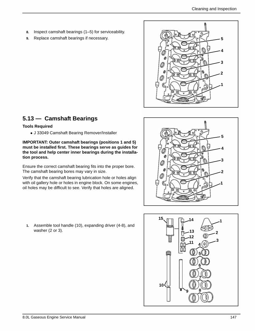
Cleaning and Inspection
8. Inspect camshaft bearings (1–5) for serviceability.
9. Replace camshaft bearings if necessary.
5.13 — Camshaft BearingsTools Required
• J 33049 Camshaft Bearing Remover/Installer
IMPORTANT: Outer camshaft bearings (positions 1 and 5) must be installed first. These bearings serve as guides for the tool and help center inner bearings during the installa-tion process.
Ensure the correct camshaft bearing fits into the proper bore. The camshaft bearing bores may vary in size.
Verify that the camshaft bearing lubrication hole or holes align with oil gallery hole or holes in engine block. On some engines, oil holes may be difficult to see. Verify that holes are aligned.
1. Assemble tool handle (10), expanding driver (4-8), and washer (2 or 3).
5
4
3
2
1
5
4
3
2
1
151
2
34
5
6
7
89
10
111213
14
8.0L Gaseous Engine Service Manual 147
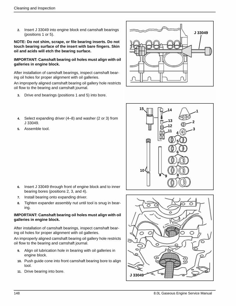
Cleaning and Inspection
2. Insert J 33049 into engine block end camshaft bearings (positions 1 or 5).
NOTE: Do not shim, scrape, or file bearing inserts. Do not touch bearing surface of the insert with bare fingers. Skin oil and acids will etch the bearing surface.
IMPORTANT: Camshaft bearing oil holes must align with oil galleries in engine block.
After installation of camshaft bearings, inspect camshaft bear-ing oil holes for proper alignment with oil galleries.
An improperly aligned camshaft bearing oil gallery hole restricts oil flow to the bearing and camshaft journal.
3. Drive end bearings (positions 1 and 5) into bore.
4. Select expanding driver (4–8) and washer (2 or 3) from J 33049.
5. Assemble tool.
6. Insert J 33049 through front of engine block and to inner bearing bores (positions 2, 3, and 4).
7. Install bearing onto expanding driver.
8. Tighten expander assembly nut until tool is snug in bear-ing.
IMPORTANT: Camshaft bearing oil holes must align with oil galleries in engine block.
After installation of camshaft bearings, inspect camshaft bear-ing oil holes for proper alignment with oil galleries.
An improperly aligned camshaft bearing oil gallery hole restricts oil flow to the bearing and camshaft journal.
9. Align oil lubrication hole in bearing with oil galleries in engine block.
10. Push guide cone into front camshaft bearing bore to align tool.
11. Drive bearing into bore.
J 33049
J 33049
151
2
34
5
6
7
89
10
111213
14
148 8.0L Gaseous Engine Service Manual
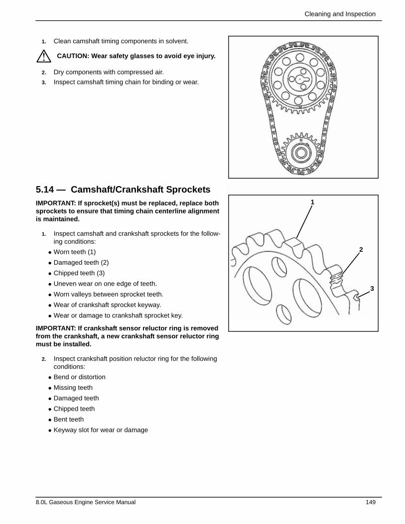
Cleaning and Inspection
1. Clean camshaft timing components in solvent.
2. Dry components with compressed air.
3. Inspect camshaft timing chain for binding or wear.
5.14 — Camshaft/Crankshaft SprocketsIMPORTANT: If sprocket(s) must be replaced, replace both sprockets to ensure that timing chain centerline alignment is maintained.
1. Inspect camshaft and crankshaft sprockets for the follow-ing conditions:
• Worn teeth (1)
• Damaged teeth (2)
• Chipped teeth (3)
• Uneven wear on one edge of teeth.
• Worn valleys between sprocket teeth.
• Wear of crankshaft sprocket keyway.
• Wear or damage to crankshaft sprocket key.
IMPORTANT: If crankshaft sensor reluctor ring is removed from the crankshaft, a new crankshaft sensor reluctor ring must be installed.
2. Inspect crankshaft position reluctor ring for the following conditions:
• Bend or distortion
• Missing teeth
• Damaged teeth
• Chipped teeth
• Bent teeth
• Keyway slot for wear or damage
CAUTION: Wear safety glasses to avoid eye injury.
1
2
3
*
8.0L Gaseous Engine Service Manual 149
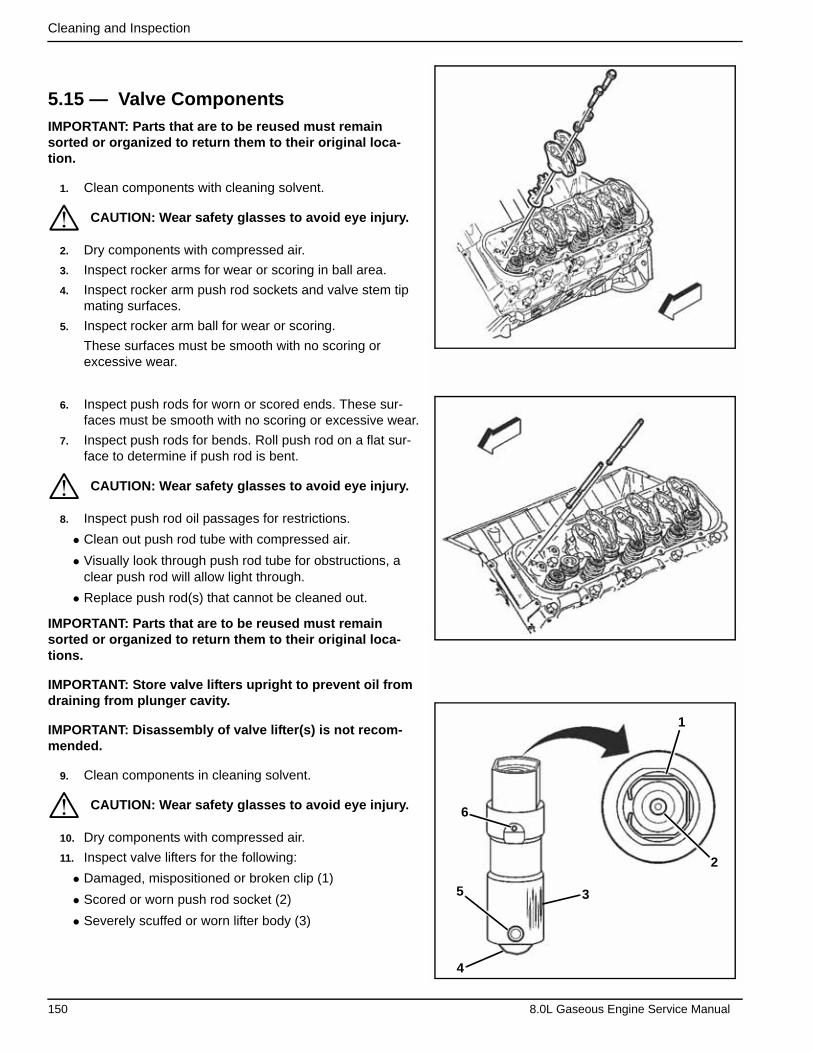
Cleaning and Inspection
5.15 — Valve Components IMPORTANT: Parts that are to be reused must remain sorted or organized to return them to their original loca-tion.
1. Clean components with cleaning solvent.
2. Dry components with compressed air.
3. Inspect rocker arms for wear or scoring in ball area.
4. Inspect rocker arm push rod sockets and valve stem tip mating surfaces.
5. Inspect rocker arm ball for wear or scoring.
These surfaces must be smooth with no scoring or excessive wear.
6. Inspect push rods for worn or scored ends. These sur-faces must be smooth with no scoring or excessive wear.
7. Inspect push rods for bends. Roll push rod on a flat sur-face to determine if push rod is bent.
8. Inspect push rod oil passages for restrictions.
• Clean out push rod tube with compressed air.
• Visually look through push rod tube for obstructions, a clear push rod will allow light through.
• Replace push rod(s) that cannot be cleaned out.
IMPORTANT: Parts that are to be reused must remain sorted or organized to return them to their original loca-tions.
IMPORTANT: Store valve lifters upright to prevent oil from draining from plunger cavity.
IMPORTANT: Disassembly of valve lifter(s) is not recom-mended.
9. Clean components in cleaning solvent.
10. Dry components with compressed air.
11. Inspect valve lifters for the following:
• Damaged, mispositioned or broken clip (1)
• Scored or worn push rod socket (2)
• Severely scuffed or worn lifter body (3)
CAUTION: Wear safety glasses to avoid eye injury.
CAUTION: Wear safety glasses to avoid eye injury.
CAUTION: Wear safety glasses to avoid eye injury. 6
1
2
35
4
*
*
*
150 8.0L Gaseous Engine Service Manual
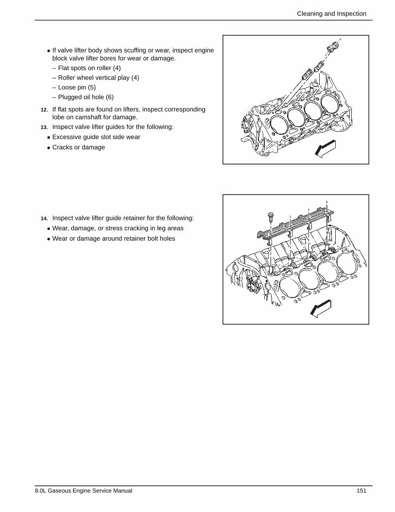
Cleaning and Inspection
• If valve lifter body shows scuffing or wear, inspect engine block valve lifter bores for wear or damage.
– Flat spots on roller (4)
– Roller wheel vertical play (4)
– Loose pin (5)
– Plugged oil hole (6)
12. If flat spots are found on lifters, inspect corresponding lobe on camshaft for damage.
13. Inspect valve lifter guides for the following:
• Excessive guide slot side wear
• Cracks or damage
14. Inspect valve lifter guide retainer for the following:
• Wear, damage, or stress cracking in leg areas
• Wear or damage around retainer bolt holes
8.0L Gaseous Engine Service Manual 151

Cleaning and Inspection
Tools Required
• J 8062 Valve Spring Compressor
IMPORTANT: Mark, sort, or organize components for return to their original locations.
1. Use J 8062 to compress valve springs.
2. Remove valve stem keys (1).
3. Release and remove J 8062.
4. Remove cap (2).
5. Remove valve spring (3).
6. Remove valve stem oil seal (4).
7. Remove valve rotator (5).
NOTE: Do not damage valve guide. Remove any burrs that have formed at the key groove by chamfering the valve stem with an oil stone or a file.
8. Remove valve.
9. Remove ECT sensor hole plug, if required.
CAUTION: Wear safety glasses to avoid eye injury.
CAUTION: Compressed valve springs have high tension against the valve spring compressor. Valve springs that are not properly compressed by or released from the valve spring compressor can be ejected from the valve spring compressor with intense force. Use care when compressing or releasing the valve spring with the valve spring compressor and when removing or installing the valve stem keys. Failing to use care may cause per-sonal injury.
J 8062
4 5
3 2
1
*
*
152 8.0L Gaseous Engine Service Manual
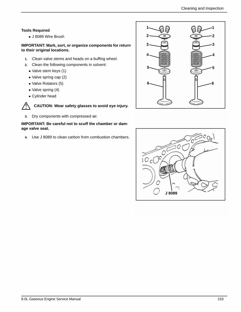
Cleaning and Inspection
Tools Required
• J 8089 Wire Brush
IMPORTANT: Mark, sort, or organize components for return to their original locations.
1. Clean valve stems and heads on a buffing wheel.
2. Clean the following components in solvent:
• Valve stem keys (1)
• Valve spring cap (2)
• Valve Rotators (5)
• Valve spring (4)
• Cylinder head
3. Dry components with compressed air.
IMPORTANT: Be careful not to scuff the chamber or dam-age valve seat.
4. Use J 8089 to clean carbon from combustion chambers.
CAUTION: Wear safety glasses to avoid eye injury.
1 1
2
3
4
5
6
2
3
4
5
6
J 8089
*
8.0L Gaseous Engine Service Manual 153
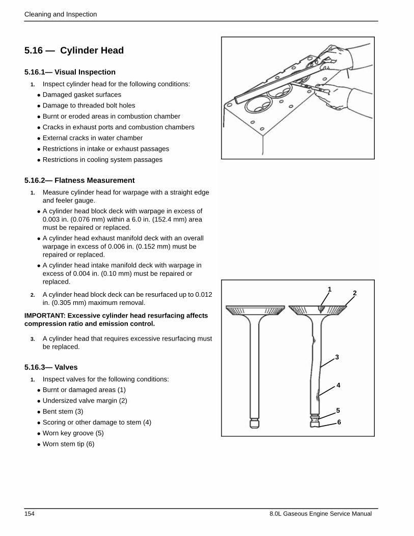
Cleaning and Inspection
5.16 — Cylinder Head
5.16.1— Visual Inspection
1. Inspect cylinder head for the following conditions:
• Damaged gasket surfaces
• Damage to threaded bolt holes
• Burnt or eroded areas in combustion chamber
• Cracks in exhaust ports and combustion chambers
• External cracks in water chamber
• Restrictions in intake or exhaust passages
• Restrictions in cooling system passages
5.16.2— Flatness Measurement
1. Measure cylinder head for warpage with a straight edge and feeler gauge.
• A cylinder head block deck with warpage in excess of 0.003 in. (0.076 mm) within a 6.0 in. (152.4 mm) area must be repaired or replaced.
• A cylinder head exhaust manifold deck with an overall warpage in excess of 0.006 in. (0.152 mm) must be repaired or replaced.
• A cylinder head intake manifold deck with warpage in excess of 0.004 in. (0.10 mm) must be repaired or replaced.
2. A cylinder head block deck can be resurfaced up to 0.012 in. (0.305 mm) maximum removal.
IMPORTANT: Excessive cylinder head resurfacing affects compression ratio and emission control.
3. A cylinder head that requires excessive resurfacing must be replaced.
5.16.3— Valves
1. Inspect valves for the following conditions:
• Burnt or damaged areas (1)
• Undersized valve margin (2)
• Bent stem (3)
• Scoring or other damage to stem (4)
• Worn key groove (5)
• Worn stem tip (6)
4
3
2 1
5
6
154 8.0L Gaseous Engine Service Manual

Cleaning and Inspection
2. Inspect valve contact surface for the following conditions:
• Undersized margin (1)
• Severely pitted surface (2)
• Burnt or eroded areas (3)
• Acceptable edge (margin) (4)
IMPORTANT: Light pitting of valve face is normal after use and is not detrimental to valve function.
IMPORTANT: Minor imperfections of the valve may be cor-rected during reconditioning.
3. Valves with excessive damage must be replaced.
5.16.4— Measurement Valve Springs
Tools Required
• J 9666 Valve Spring Tester
1. Inspect valve springs for broken coils or coil ends.
2. Use J 9666 to measure valve spring force. See Engine Tolerances and Wear Limits in Section 1.
IMPORTANT: Add a maximum of one shim up to 0.030 in. (0.726 mm) thick to increase tension.
3. If valve spring tension is low, use a shim to increase ten-sion.
4. Recheck valve spring tension. A valve spring that does not meet specification must be replaced.
5.16.5— Measure Valve Guides
Tools Required
• J 8001 Dial Indicator Set
IMPORTANT: Excessive valve stem-to-guide clearance may cause an excessive oil consumption and may also cause a valve to break. Insufficient clearance will result in noisy and sticky functioning of the valve and will disturb the engine assembly smoothness.
1. Measure valve stem-to-guide clearance.
• Clamp J 8001 on exhaust port side of cylinder head.
IMPORTANT: Indicator stem must contact side of valve stem just above valve guide.
• Locate indicator so that movement of the valve stem from side to side (crosswise to the cylinder head) will cause a direct movement of the indicator stem.
J 9666
J 8001
2
1
3
4
8.0L Gaseous Engine Service Manual 155
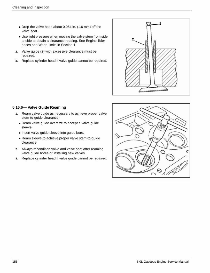
Cleaning and Inspection
• Drop the valve head about 0.064 in. (1.6 mm) off the valve seat.
• Use light pressure when moving the valve stem from side to side to obtain a clearance reading. See Engine Toler-ances and Wear Limits in Section 1.
2. Valve guide (2) with excessive clearance must be repaired.
3. Replace cylinder head if valve guide cannot be repaired.
5.16.6— Valve Guide Reaming
1. Ream valve guide as necessary to achieve proper valve stem-to-guide clearance.
• Ream valve guide oversize to accept a valve guide sleeve.
• Insert valve guide sleeve into guide bore.
• Ream sleeve to achieve proper valve stem-to-guide clearance.
2. Always recondition valve and valve seat after reaming valve guide bores or installing new valves.
3. Replace cylinder head if valve guide cannot be repaired.
1
2
156 8.0L Gaseous Engine Service Manual
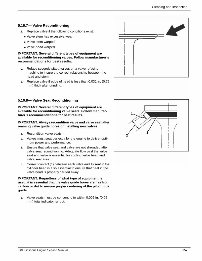
Cleaning and Inspection
5.16.7— Valve Reconditioning
1. Replace valve if the following conditions exist:
• Valve stem has excessive wear
• Valve stem warped
• Valve head warped
IMPORTANT: Several different types of equipment are available for reconditioning valves. Follow manufacturer’s recommendations for best results.
2. Reface severely pitted valves on a valve refacing machine to insure the correct relationship between the head and stem.
3. Replace valve if edge of head is less than 0.031 in. (0.79 mm) thick after grinding.
5.16.8— Valve Seat Reconditioning
IMPORTANT: Several different types of equipment are available for reconditioning valve seats. Follow manufac-turer’s recommendations for best results.
IMPORTANT: Always recondition valve and valve seat after reaming valve guide bores or installing new valves.
1. Recondition valve seats.
2. Valves must seat perfectly for the engine to deliver opti-mum power and performance.
3. Ensure that valve seat and valve are not shrouded after valve seat reconditioning. Adequate flow past the valve seat and valve is essential for cooling valve head and valve seat area.
4. Correct contact (1) between each valve and its seat in the cylinder head is also essential to ensure that heat in the valve head is properly carried away.
IMPORTANT: Regardless of what type of equipment is used, it is essential that the valve guide bores are free from carbon or dirt to ensure proper centering of the pilot in the guide.
5. Valve seats must be concentric to within 0.002 in. (0.05 mm) total indicator runout.
32
1
8.0L Gaseous Engine Service Manual 157

Cleaning and Inspection
5.16.9— Valve Installation
Tools Required
• J 8062 Valve Spring Compressor
1. Lubricate valve stems with clean engine oil.
2. Insert valves into their proper locations.
3. Lubricate rotators with clean engine oil (5).
4. Install rotators over the guide and onto the cylinder head.
IMPORTANT: When installing valve stem oil seals onto valve guides be careful not to tear or dislocate seal lip.
5. Install oil seal (3) onto valve guide.
6. Install valve spring (4).
7. Install cap (2).
8. Use J 8062 to compress valve spring.
Compress spring enough to clearly see valve stem key grooves.
9. Install valve stem keys (1).
• Use grease to hold keys in place.
• Verify that keys seat properly in groove of valve stem.
• Release J 8062.
• Remove J 8062.
• Tap end of stem with a soft hammer to verify that keys will not come free.
5.16.10— Check Valve Spring Installed Height
1. Measure valve spring for properly installed height. Refer to Engine Mechanical Specifications for proper valve spring installed height specifications.
Use a thin scale and measure from cylinder head spring seat to top of spring cap.
IMPORTANT: Never shim spring to obtain an installed height under the specified amount.
IMPORTANT: Install valve spring seat shims under the rota-tor (between rotator and cylinder head spring seat).
IMPORTANT: Add a maximum of one valve spring seat shim, up to 0.030 in. (0.726 mm) thick to achieve the valve spring installed height specification.
1 1
2
3
4
5
6
2
3
4
5
6
J 8062
158 8.0L Gaseous Engine Service Manual
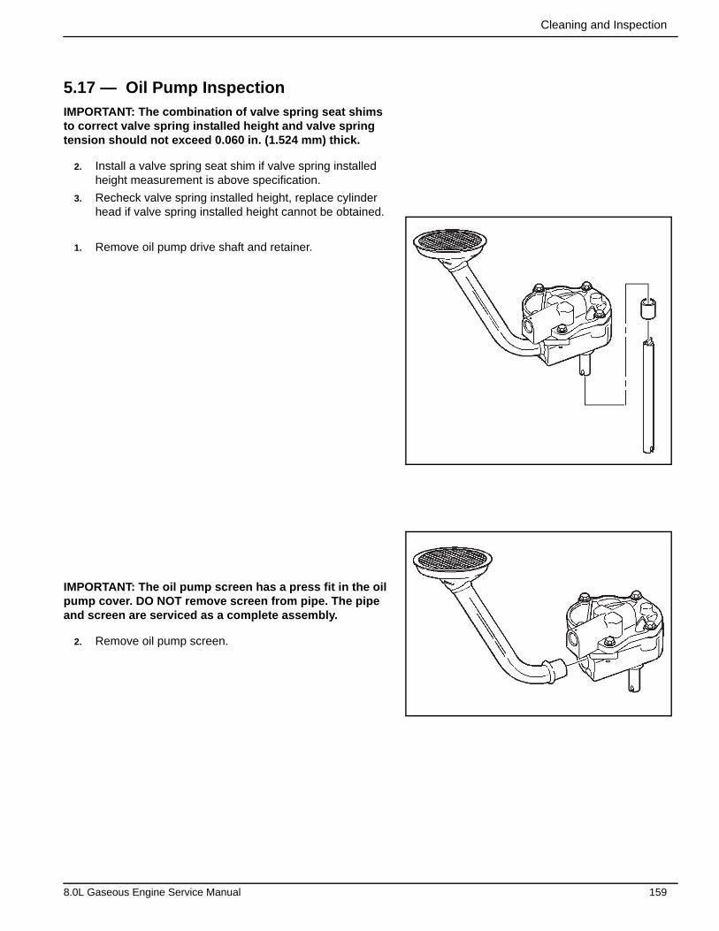
Cleaning and Inspection
5.17 — Oil Pump InspectionIMPORTANT: The combination of valve spring seat shims to correct valve spring installed height and valve spring tension should not exceed 0.060 in. (1.524 mm) thick.
2. Install a valve spring seat shim if valve spring installed height measurement is above specification.
3. Recheck valve spring installed height, replace cylinder head if valve spring installed height cannot be obtained.
1. Remove oil pump drive shaft and retainer.
IMPORTANT: The oil pump screen has a press fit in the oil pump cover. DO NOT remove screen from pipe. The pipe and screen are serviced as a complete assembly.
2. Remove oil pump screen.
8.0L Gaseous Engine Service Manual 159

Cleaning and Inspection
3. Remove oil pump cover bolts.
4. Remove oil pump cover and cover-to-body gasket.
5. Match mark driven gear (1) and drive gear (2).
1 2
160 8.0L Gaseous Engine Service Manual

Cleaning and Inspection
6. Remove drive gear and driven gear. Matchmark gear teeth for assembly.
7. Remove the following items:
• Retaining pin
• Pressure relief spring
• Pressure relief valve
1. Clean oil pump components in cleaning solvent.
2. Dry components with compressed air.
3. Inspect oil pump for the following:
• Scoring on top of gears (1)
• Damaged gears (2) for the following:
– Chipping
– Galling
– Wear
• Scoring, damage or casting imperfections to the body (3)
• Damaged or scored gear shaft (4)
• Damaged or scored gear shaft (5)
CAUTION: Wear safety glasses to avoid eye injury.
1
2
5
3
4
*
8.0L Gaseous Engine Service Manual 161
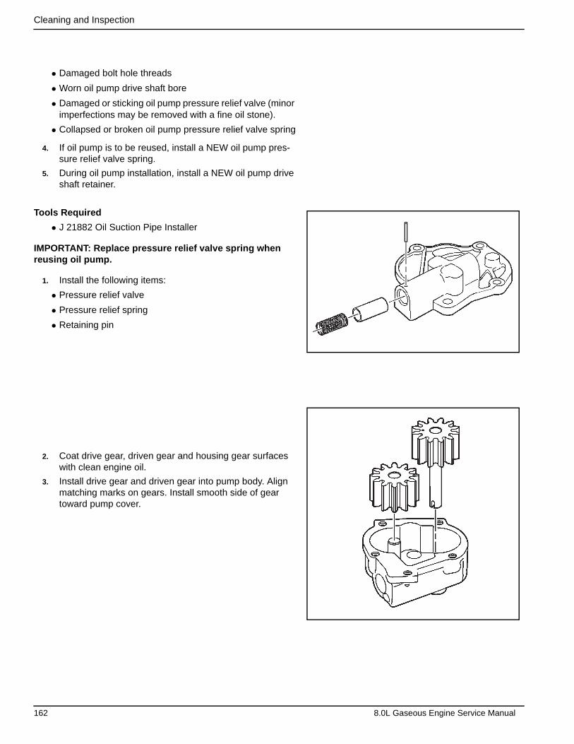
Cleaning and Inspection
• Damaged bolt hole threads
• Worn oil pump drive shaft bore
• Damaged or sticking oil pump pressure relief valve (minor imperfections may be removed with a fine oil stone).
• Collapsed or broken oil pump pressure relief valve spring
4. If oil pump is to be reused, install a NEW oil pump pres-sure relief valve spring.
5. During oil pump installation, install a NEW oil pump drive shaft retainer.
Tools Required
• J 21882 Oil Suction Pipe Installer
IMPORTANT: Replace pressure relief valve spring when reusing oil pump.
1. Install the following items:
• Pressure relief valve
• Pressure relief spring
• Retaining pin
2. Coat drive gear, driven gear and housing gear surfaces with clean engine oil.
3. Install drive gear and driven gear into pump body. Align matching marks on gears. Install smooth side of gear toward pump cover.
162 8.0L Gaseous Engine Service Manual
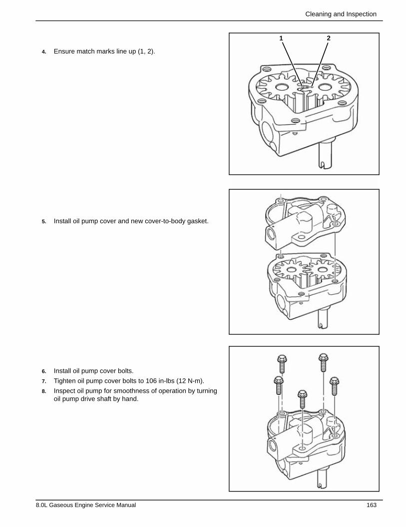
Cleaning and Inspection
4. Ensure match marks line up (1, 2).
5. Install oil pump cover and new cover-to-body gasket.
6. Install oil pump cover bolts.
7. Tighten oil pump cover bolts to 106 in-lbs (12 N-m).
8. Inspect oil pump for smoothness of operation by turning oil pump drive shaft by hand.
1 2
8.0L Gaseous Engine Service Manual 163
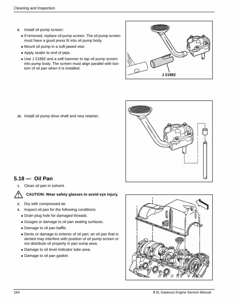
Cleaning and Inspection
9. Install oil pump screen:
• If removed, replace oil pump screen. The oil pump screen must have a good press fit into oil pump body.
• Mount oil pump in a soft-jawed vise.
• Apply sealer to end of pipe.
• Use J 21882 and a soft hammer to tap oil pump screen into pump body. The screen must align parallel with bot-tom of oil pan when it is installed.
10. Install oil pump drive shaft and new retainer.
5.18 — Oil Pan1. Clean oil pan in solvent.
2. Dry with compressed air.
3. Inspect oil pan for the following conditions:
• Drain plug hole for damaged threads.
• Gouges or damage to oil pan sealing surfaces.
• Damage to oil pan baffle.
• Dents or damage to exterior of oil pan; an oil pan that is dented may interfere with position of oil pump screen or not distribute oil properly in pan sump area.
• Damage to oil level indicator tube area.
• Damage to oil pan gasket.
CAUTION: Wear safety glasses to avoid eye injury.
J 21882
*
164 8.0L Gaseous Engine Service Manual
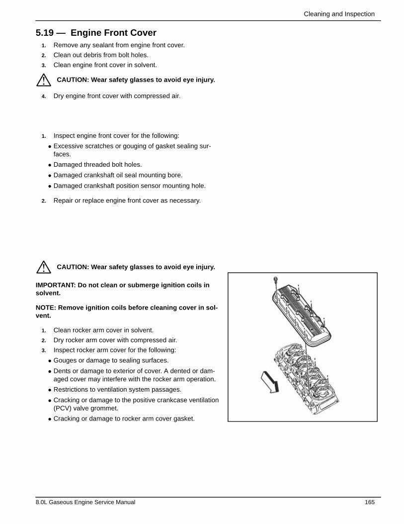
Cleaning and Inspection
5.19 — Engine Front Cover1. Remove any sealant from engine front cover.
2. Clean out debris from bolt holes.
3. Clean engine front cover in solvent.
4. Dry engine front cover with compressed air.
1. Inspect engine front cover for the following:
• Excessive scratches or gouging of gasket sealing sur-faces.
• Damaged threaded bolt holes.
• Damaged crankshaft oil seal mounting bore.
• Damaged crankshaft position sensor mounting hole.
2. Repair or replace engine front cover as necessary.
IMPORTANT: Do not clean or submerge ignition coils in solvent.
NOTE: Remove ignition coils before cleaning cover in sol-vent.
1. Clean rocker arm cover in solvent.
2. Dry rocker arm cover with compressed air.
3. Inspect rocker arm cover for the following:
• Gouges or damage to sealing surfaces.
• Dents or damage to exterior of cover. A dented or dam-aged cover may interfere with the rocker arm operation.
• Restrictions to ventilation system passages.
• Cracking or damage to the positive crankcase ventilation (PCV) valve grommet.
• Cracking or damage to rocker arm cover gasket.
CAUTION: Wear safety glasses to avoid eye injury.
CAUTION: Wear safety glasses to avoid eye injury.
*
*
8.0L Gaseous Engine Service Manual 165
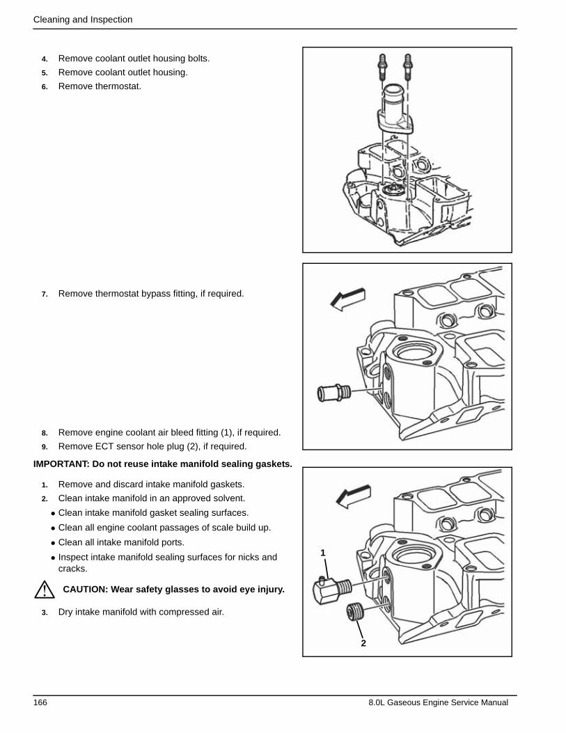
Cleaning and Inspection
4. Remove coolant outlet housing bolts.
5. Remove coolant outlet housing.
6. Remove thermostat.
7. Remove thermostat bypass fitting, if required.
8. Remove engine coolant air bleed fitting (1), if required.
9. Remove ECT sensor hole plug (2), if required.
IMPORTANT: Do not reuse intake manifold sealing gaskets.
1. Remove and discard intake manifold gaskets.
2. Clean intake manifold in an approved solvent.
• Clean intake manifold gasket sealing surfaces.
• Clean all engine coolant passages of scale build up.
• Clean all intake manifold ports.
• Inspect intake manifold sealing surfaces for nicks and cracks.
3. Dry intake manifold with compressed air.
CAUTION: Wear safety glasses to avoid eye injury.
1
2
*
166 8.0L Gaseous Engine Service Manual
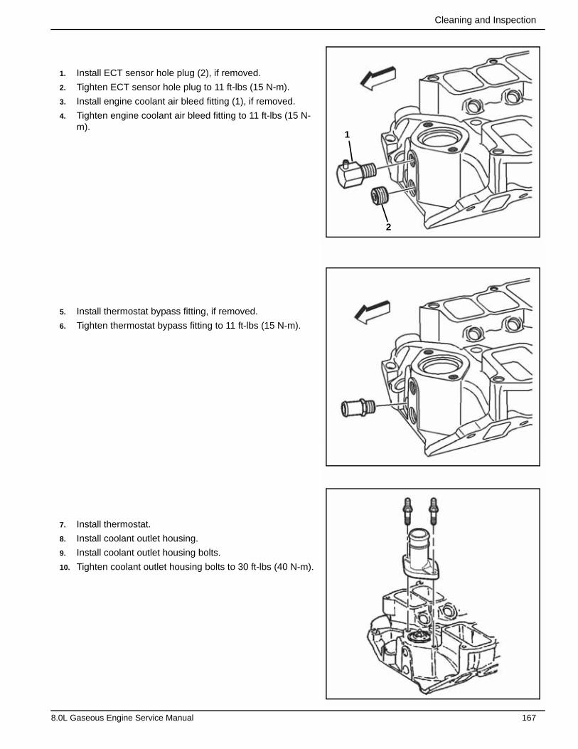
Cleaning and Inspection
1. Install ECT sensor hole plug (2), if removed.
2. Tighten ECT sensor hole plug to 11 ft-lbs (15 N-m).
3. Install engine coolant air bleed fitting (1), if removed.
4. Tighten engine coolant air bleed fitting to 11 ft-lbs (15 N-m).
5. Install thermostat bypass fitting, if removed.
6. Tighten thermostat bypass fitting to 11 ft-lbs (15 N-m).
7. Install thermostat.
8. Install coolant outlet housing.
9. Install coolant outlet housing bolts.
10. Tighten coolant outlet housing bolts to 30 ft-lbs (40 N-m).
1
2
8.0L Gaseous Engine Service Manual 167
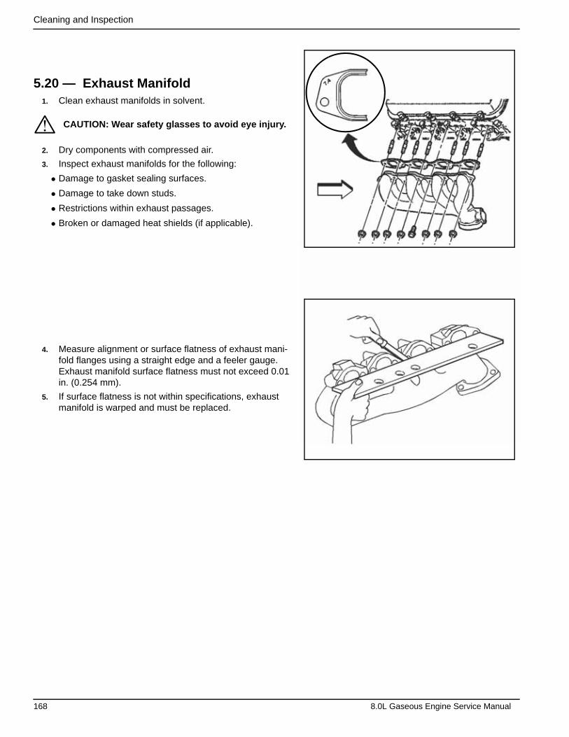
Cleaning and Inspection
5.20 — Exhaust Manifold1. Clean exhaust manifolds in solvent.
2. Dry components with compressed air.
3. Inspect exhaust manifolds for the following:
• Damage to gasket sealing surfaces.
• Damage to take down studs.
• Restrictions within exhaust passages.
• Broken or damaged heat shields (if applicable).
4. Measure alignment or surface flatness of exhaust mani-fold flanges using a straight edge and a feeler gauge. Exhaust manifold surface flatness must not exceed 0.01 in. (0.254 mm).
5. If surface flatness is not within specifications, exhaust manifold is warped and must be replaced.
CAUTION: Wear safety glasses to avoid eye injury.*
168 8.0L Gaseous Engine Service Manual
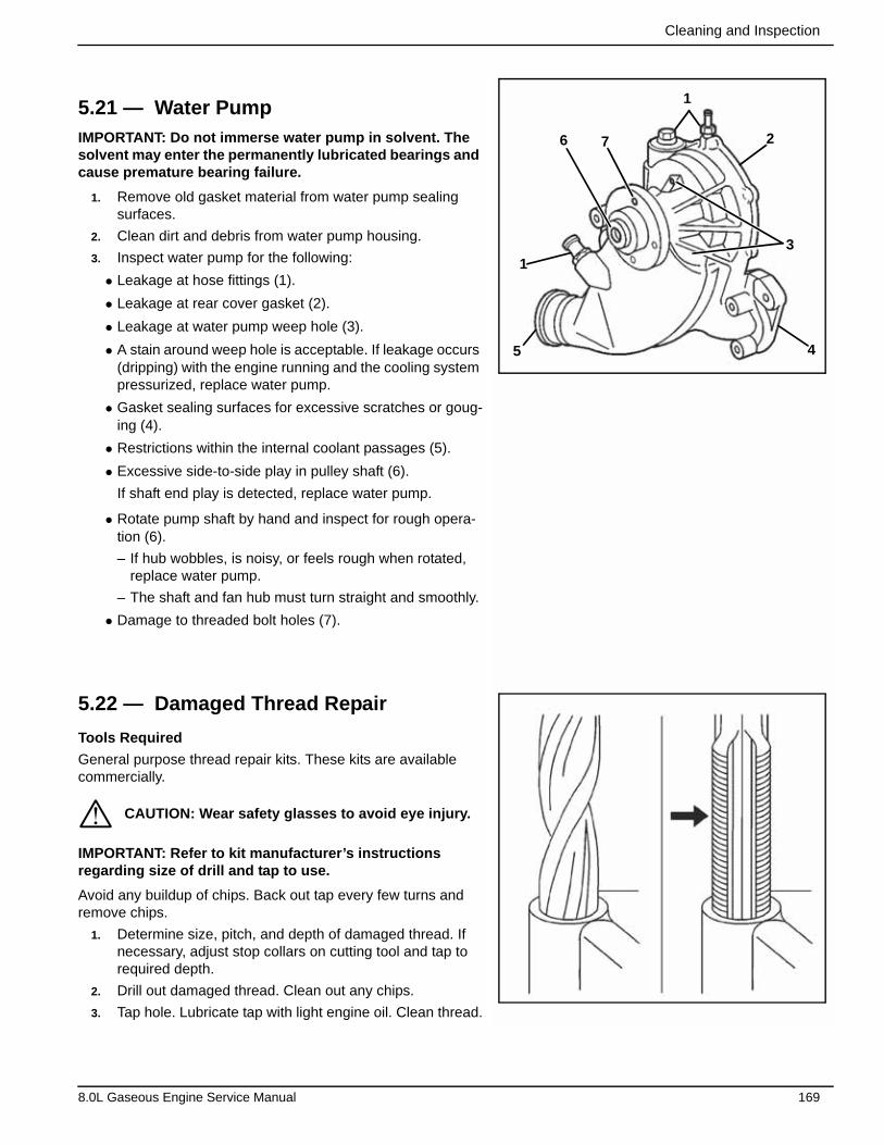
Cleaning and Inspection
5.21 — Water PumpIMPORTANT: Do not immerse water pump in solvent. The solvent may enter the permanently lubricated bearings and cause premature bearing failure.
1. Remove old gasket material from water pump sealing surfaces.
2. Clean dirt and debris from water pump housing.
3. Inspect water pump for the following:
• Leakage at hose fittings (1).
• Leakage at rear cover gasket (2).
• Leakage at water pump weep hole (3).
• A stain around weep hole is acceptable. If leakage occurs (dripping) with the engine running and the cooling system pressurized, replace water pump.
• Gasket sealing surfaces for excessive scratches or goug-ing (4).
• Restrictions within the internal coolant passages (5).
• Excessive side-to-side play in pulley shaft (6).
If shaft end play is detected, replace water pump.
• Rotate pump shaft by hand and inspect for rough opera-tion (6).
– If hub wobbles, is noisy, or feels rough when rotated, replace water pump.
– The shaft and fan hub must turn straight and smoothly.
• Damage to threaded bolt holes (7).
5.22 — Damaged Thread Repair
Tools Required
General purpose thread repair kits. These kits are available commercially.
IMPORTANT: Refer to kit manufacturer’s instructions regarding size of drill and tap to use.
Avoid any buildup of chips. Back out tap every few turns and remove chips.
1. Determine size, pitch, and depth of damaged thread. If necessary, adjust stop collars on cutting tool and tap to required depth.
2. Drill out damaged thread. Clean out any chips.
3. Tap hole. Lubricate tap with light engine oil. Clean thread.
CAUTION: Wear safety glasses to avoid eye injury.
3
276
1
5 4
1
*
8.0L Gaseous Engine Service Manual 169
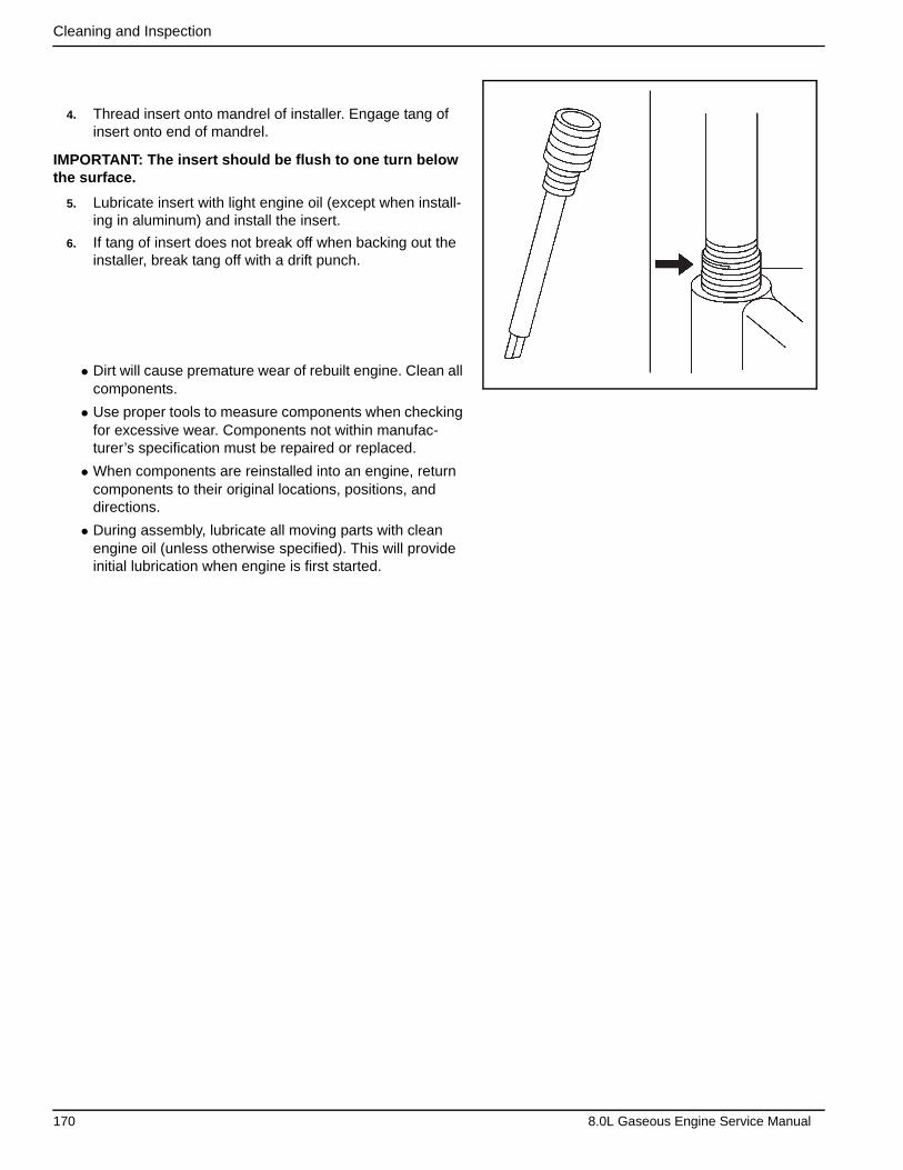
Cleaning and Inspection
4. Thread insert onto mandrel of installer. Engage tang of insert onto end of mandrel.
IMPORTANT: The insert should be flush to one turn below the surface.
5. Lubricate insert with light engine oil (except when install-ing in aluminum) and install the insert.
6. If tang of insert does not break off when backing out the installer, break tang off with a drift punch.
• Dirt will cause premature wear of rebuilt engine. Clean all components.
• Use proper tools to measure components when checking for excessive wear. Components not within manufac-turer’s specification must be repaired or replaced.
• When components are reinstalled into an engine, return components to their original locations, positions, and directions.
• During assembly, lubricate all moving parts with clean engine oil (unless otherwise specified). This will provide initial lubrication when engine is first started.
170 8.0L Gaseous Engine Service Manual
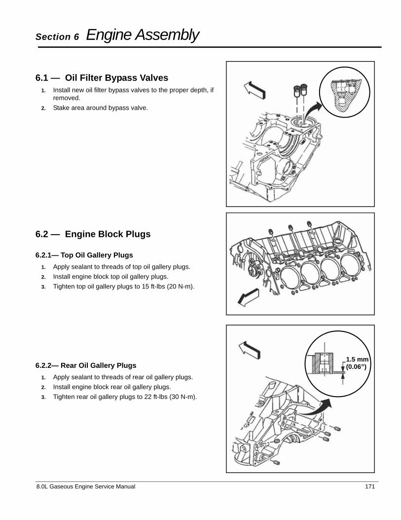
Section 6 Engine Assembly
6.1 — Oil Filter Bypass Valves1. Install new oil filter bypass valves to the proper depth, if
removed.
2. Stake area around bypass valve.
6.2 — Engine Block Plugs
6.2.1— Top Oil Gallery Plugs
1. Apply sealant to threads of top oil gallery plugs.
2. Install engine block top oil gallery plugs.
3. Tighten top oil gallery plugs to 15 ft-lbs (20 N-m).
6.2.2— Rear Oil Gallery Plugs
1. Apply sealant to threads of rear oil gallery plugs.
2. Install engine block rear oil gallery plugs.
3. Tighten rear oil gallery plugs to 22 ft-lbs (30 N-m).
1.5 mm(0.06”)
8.0L Gaseous Engine Service Manual 171
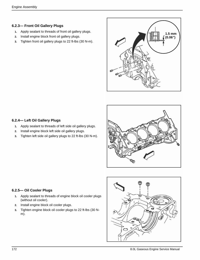
Engine Assembly
6.2.3— Front Oil Gallery Plugs
1. Apply sealant to threads of front oil gallery plugs.
2. Install engine block front oil gallery plugs.
3. Tighten front oil gallery plugs to 22 ft-lbs (30 N-m).
6.2.4— Left Oil Gallery Plugs
1. Apply sealant to threads of left side oil gallery plugs.
2. Install engine block left side oil gallery plugs.
3. Tighten left side oil gallery plugs to 22 ft-lbs (30 N-m).
6.2.5— Oil Cooler Plugs
1. Apply sealant to threads of engine block oil cooler plugs (without oil cooler).
2. Install engine block oil cooler plugs.
3. Tighten engine block oil cooler plugs to 22 ft-lbs (30 N-m).
1.5 mm(0.06”)
172 8.0L Gaseous Engine Service Manual

Engine Assembly
6.2.6— Oil Cooler Hose Fittings
1. Apply sealant to threads of engine block oil cooler hose fittings (with oil cooler).
2. Install engine block oil cooler hose fittings.
3. Tighten engine block oil cooler hose fittings to 17 ft-lbs (23 N-m).
6.2.7— Coolant Drain Plug
1. Apply sealant to threads of engine block coolant drain hole plug.
2. Install engine block coolant drain hole plug.
3. Tighten engine block coolant drain hole plug to 15 ft-lbs (20 N-m).
6.2.8— Knock Sensors/Knock Sensor Shields
1. Apply sealant to threads of knock sensors.
2. Install left knock sensor (1) to engine block.
3. Tighten left knock sensor to 14 ft-lbs (19 N-m).
4. Install right knock sensor (2) to engine block.
5. Tighten right knock sensor to 14 ft-lbs (19 N-m).
1
2
8.0L Gaseous Engine Service Manual 173
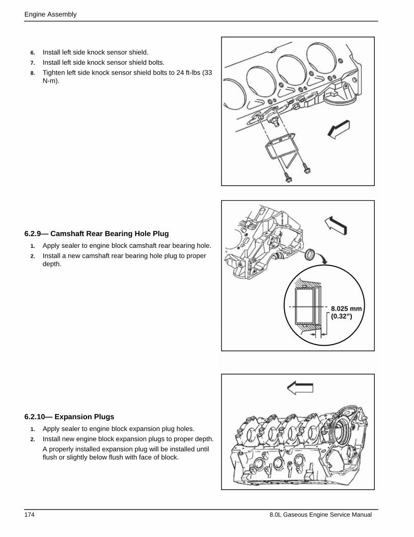
Engine Assembly
6. Install left side knock sensor shield.
7. Install left side knock sensor shield bolts.
8. Tighten left side knock sensor shield bolts to 24 ft-lbs (33 N-m).
6.2.9— Camshaft Rear Bearing Hole Plug
1. Apply sealer to engine block camshaft rear bearing hole.
2. Install a new camshaft rear bearing hole plug to proper depth.
6.2.10— Expansion Plugs
1. Apply sealer to engine block expansion plug holes.
2. Install new engine block expansion plugs to proper depth.
A properly installed expansion plug will be installed until flush or slightly below flush with face of block.
8.025 mm(0.32”)
174 8.0L Gaseous Engine Service Manual

Engine Assembly
6.3 — Oil Bypass Valves1. Install new oil bypass valves, if removed. Stake tangs on
oil bypass valves.
6.4 — Oil Filter Fitting1. Install oil filter fitting.
2. Tighten oil filter fitting to 49 ft-lbs (66 N-m).
6.5 — Crankshaft/Crankshaft BearingsNOTE: Do not shim, scrape, or file bearing inserts. Do not touch bearing surface of the insert with bare fingers. Skin oil and acids will etch the bearing surface.
IMPORTANT: If undersized bearings are used, ensure that bearings are fitted to the proper journals. Lubricate crank-shaft bearings and crankshaft with clean engine oil.
1. Install crankshaft upper bearings (1–3) into engine block.
21
3
8.0L Gaseous Engine Service Manual 175

Engine Assembly
2. Install crankshaft lower bearings (1–3) into crankshaft bearing caps.
3. Install crankshaft.
NOTE: To prevent the possibility of cylinder block or crank-shaft bearing cap damage, the crankshaft bearing caps are tapped into the cylinder block cavity using a brass, lead, or a leather mallet before the attaching bolts are installed. Do not use attaching bolts to pull crankshaft bearing caps into the seats. Failure to use this process may damage a cylin-der block or a bearing cap.
IMPORTANT: Ensure that the triangle symbol on the crank-shaft bearings caps are facing the front of the engine. DO NOT install the crankshaft rear bearing cap at this time.
4. Install crankshaft bearing caps.
1 2
3
176 8.0L Gaseous Engine Service Manual
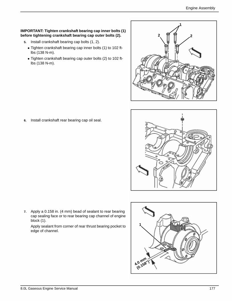
Engine Assembly
IMPORTANT: Tighten crankshaft bearing cap inner bolts (1) before tightening crankshaft bearing cap outer bolts (2).
5. Install crankshaft bearing cap bolts (1, 2).
• Tighten crankshaft bearing cap inner bolts (1) to 102 ft-lbs (138 N-m).
• Tighten crankshaft bearing cap outer bolts (2) to 102 ft-lbs (138 N-m).
6. Install crankshaft rear bearing cap oil seal.
7. Apply a 0.158 in. (4 mm) bead of sealant to rear bearing cap sealing face or to rear bearing cap channel of engine block (1).
Apply sealant from corner of rear thrust bearing pocket to edge of channel.
4.0 mm
(0.158”)
2
1
1
2
8.0L Gaseous Engine Service Manual 177
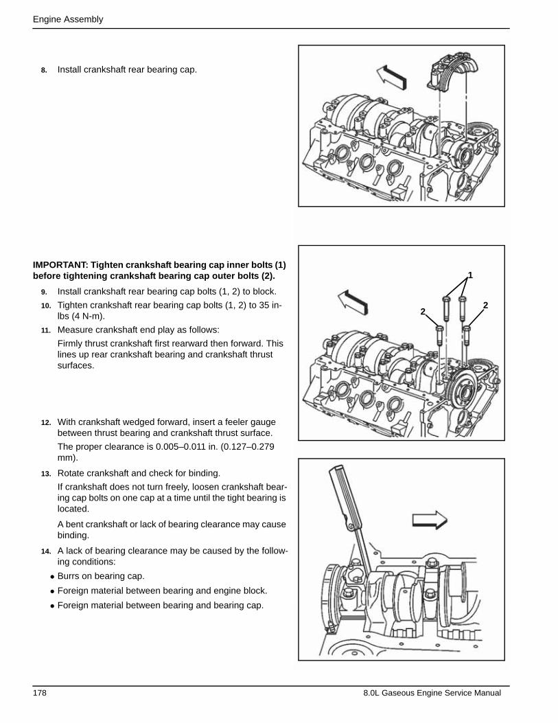
Engine Assembly
8. Install crankshaft rear bearing cap.
IMPORTANT: Tighten crankshaft bearing cap inner bolts (1) before tightening crankshaft bearing cap outer bolts (2).
9. Install crankshaft rear bearing cap bolts (1, 2) to block.
10. Tighten crankshaft rear bearing cap bolts (1, 2) to 35 in-lbs (4 N-m).
11. Measure crankshaft end play as follows:
Firmly thrust crankshaft first rearward then forward. This lines up rear crankshaft bearing and crankshaft thrust surfaces.
12. With crankshaft wedged forward, insert a feeler gauge between thrust bearing and crankshaft thrust surface.
The proper clearance is 0.005–0.011 in. (0.127–0.279 mm).
13. Rotate crankshaft and check for binding.
If crankshaft does not turn freely, loosen crankshaft bear-ing cap bolts on one cap at a time until the tight bearing is located.
A bent crankshaft or lack of bearing clearance may cause binding.
14. A lack of bearing clearance may be caused by the follow-ing conditions:
• Burrs on bearing cap.
• Foreign material between bearing and engine block.
• Foreign material between bearing and bearing cap.
2
1
2
178 8.0L Gaseous Engine Service Manual
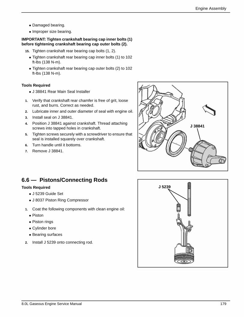
Engine Assembly
• Damaged bearing.
• Improper size bearing.
IMPORTANT: Tighten crankshaft bearing cap inner bolts (1) before tightening crankshaft bearing cap outer bolts (2).
15. Tighten crankshaft rear bearing cap bolts (1, 2).
• Tighten crankshaft rear bearing cap inner bolts (1) to 102 ft-lbs (138 N-m).
• Tighten crankshaft rear bearing cap outer bolts (2) to 102 ft-lbs (138 N-m).
Tools Required
• J 38841 Rear Main Seal Installer
1. Verify that crankshaft rear chamfer is free of grit, loose rust, and burrs. Correct as needed.
2. Lubricate inner and outer diameter of seal with engine oil.
3. Install seal on J 38841.
4. Position J 38841 against crankshaft. Thread attaching screws into tapped holes in crankshaft.
5. Tighten screws securely with a screwdriver to ensure that seal is installed squarely over crankshaft.
6. Turn handle until it bottoms.
7. Remove J 38841.
6.6 — Pistons/Connecting RodsTools Required
• J 5239 Guide Set
• J 8037 Piston Ring Compressor
1. Coat the following components with clean engine oil:
• Piston
• Piston rings
• Cylinder bore
• Bearing surfaces
2. Install J 5239 onto connecting rod.
J 38841
J 5239
8.0L Gaseous Engine Service Manual 179

Engine Assembly
NOTE: Do not shim, scrape, or file bearing inserts. Do not touch bearing surface of the insert with bare fingers. Skin oil and acids will etch the bearing surface.
IMPORTANT: The mark on the top of the piston must face the front of the engine block. When assembled, the flanges on the connecting rod and cap should face to the front of block on the left bank and to the rear of block on the right bank.
3. Install piston, connecting rod and upper connecting rod bearing through top of engine block using J 5239.
4. Install J 8037 onto piston and compress piston rings.
5. Use J 8037 and J 5239 and lightly tap top of piston with a wooden hammer handle.
6. Hold J 8037 firmly against engine block until all piston rings have entered cylinder bore.
7. Use J 5239 to guide connecting rod onto crankshaft jour-nal.
8. Remove J 5239.
J 5239
J 8037
J 5239
180 8.0L Gaseous Engine Service Manual
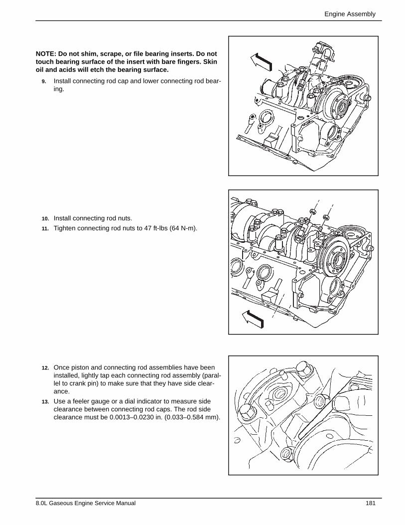
Engine Assembly
NOTE: Do not shim, scrape, or file bearing inserts. Do not touch bearing surface of the insert with bare fingers. Skin oil and acids will etch the bearing surface.
9. Install connecting rod cap and lower connecting rod bear-ing.
10. Install connecting rod nuts.
11. Tighten connecting rod nuts to 47 ft-lbs (64 N-m).
12. Once piston and connecting rod assemblies have been installed, lightly tap each connecting rod assembly (paral-lel to crank pin) to make sure that they have side clear-ance.
13. Use a feeler gauge or a dial indicator to measure side clearance between connecting rod caps. The rod side clearance must be 0.0013–0.0230 in. (0.033–0.584 mm).
8.0L Gaseous Engine Service Manual 181

Engine Assembly
6.7 — Camshaft1. Lubricate the following components with clean engine oil,
or engine oil supplement:
• Camshaft lobes
• Camshaft bearing journals
• Camshaft bearings
NOTE: All camshaft journals are the same diameter, so care must be used in removing or installing the camshaft to avoid damage to the camshaft bearings.
2. Install three 5/16–18 x 4.0 inch bolts in camshaft front bolt holes.
3. Using bolts as a handle, install camshaft.
4. Remove three bolts from front of camshaft.
5. Install camshaft retainer.
6. Install camshaft retainer bolts.
7. Tighten camshaft retainer bolts to 106 in-lbs (12 N-m).
6.8 — Crankshaft/Camshaft SprocketsTools Required
• J 22102 Front Cover Oil Seal Installer
• J 7872 Magnetic Base Dial Indicator Set
1. Properly install crankshaft key into crankshaft keyway.
2.00 mm(0.07”)1.00 mm
(0.03”)
182 8.0L Gaseous Engine Service Manual
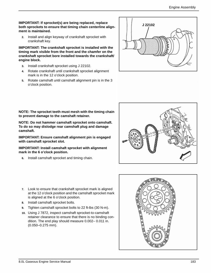
Engine Assembly
IMPORTANT: If sprocket(s) are being replaced, replace both sprockets to ensure that timing chain centerline align-ment is maintained.
2. Install and align keyway of crankshaft sprocket with crankshaft key.
IMPORTANT: The crankshaft sprocket is installed with the timing mark visible from the front and the chamfer on the crankshaft sprocket bore installed towards the crankshaft/engine block.
3. Install crankshaft sprocket using J 22102.
4. Rotate crankshaft until crankshaft sprocket alignment mark is in the 12 o’clock position.
5. Rotate camshaft until camshaft alignment pin is in the 3 o’clock position.
NOTE: The sprocket teeth must mesh with the timing chain to prevent damage to the camshaft retainer.
NOTE: Do not hammer camshaft sprocket onto camshaft. To do so may dislodge rear camshaft plug and damage camshaft.
IMPORTANT: Ensure camshaft alignment pin is engaged with camshaft sprocket slot.
IMPORTANT: Install camshaft sprocket with alignment mark in the 6 o’clock position.
6. Install camshaft sprocket and timing chain.
7. Look to ensure that crankshaft sprocket mark is aligned at the 12 o’clock position and the camshaft sprocket mark is aligned at the 6 o’clock position.
8. Install camshaft sprocket bolts.
9. Tighten camshaft sprocket bolts to 22 ft-lbs (30 N-m).
10. Using J 7872, inspect camshaft sprocket-to-camshaft retainer clearance to ensure that there is no binding con-dition. The end play should measure 0.002– 0.011 in. (0.050–0.275 mm).
J 22102
8.0L Gaseous Engine Service Manual 183
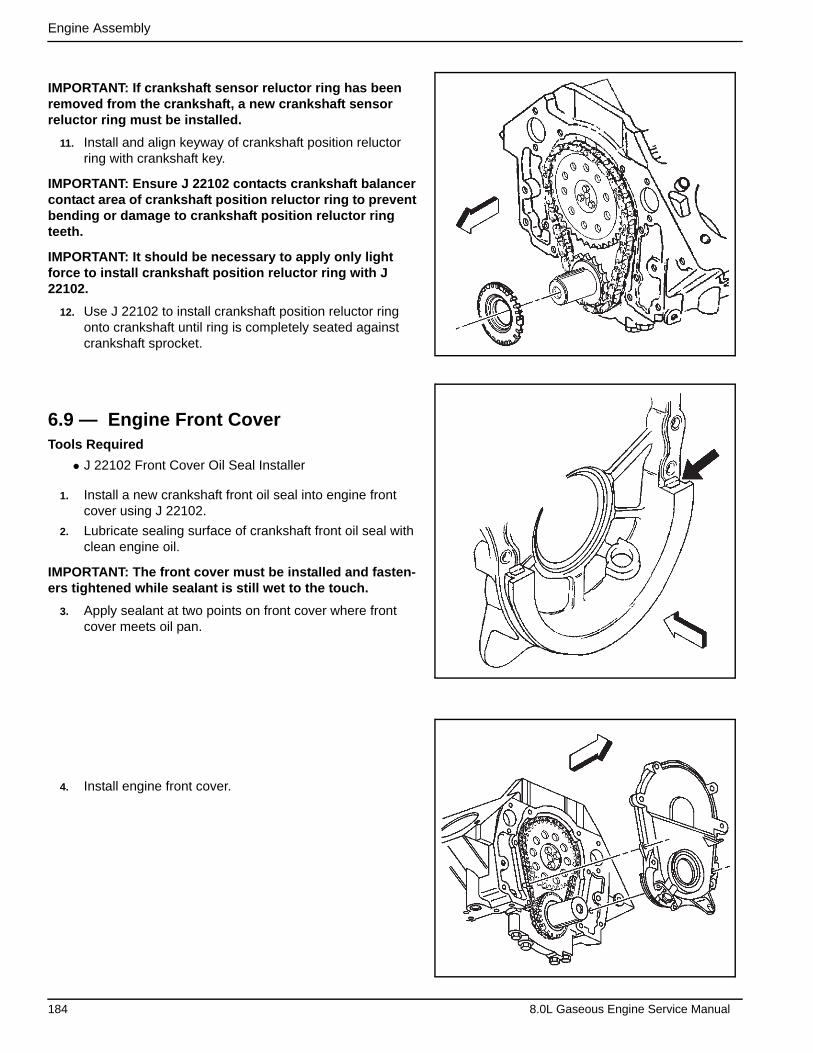
Engine Assembly
IMPORTANT: If crankshaft sensor reluctor ring has been removed from the crankshaft, a new crankshaft sensor reluctor ring must be installed.
11. Install and align keyway of crankshaft position reluctor ring with crankshaft key.
IMPORTANT: Ensure J 22102 contacts crankshaft balancer contact area of crankshaft position reluctor ring to prevent bending or damage to crankshaft position reluctor ring teeth.
IMPORTANT: It should be necessary to apply only light force to install crankshaft position reluctor ring with J 22102.
12. Use J 22102 to install crankshaft position reluctor ring onto crankshaft until ring is completely seated against crankshaft sprocket.
6.9 — Engine Front CoverTools Required
• J 22102 Front Cover Oil Seal Installer
1. Install a new crankshaft front oil seal into engine front cover using J 22102.
2. Lubricate sealing surface of crankshaft front oil seal with clean engine oil.
IMPORTANT: The front cover must be installed and fasten-ers tightened while sealant is still wet to the touch.
3. Apply sealant at two points on front cover where front cover meets oil pan.
4. Install engine front cover.
184 8.0L Gaseous Engine Service Manual

Engine Assembly
5. Install engine front cover bolts (1).
6. Tighten engine front cover bolts (1) to 106 in-lbs (12 N-m).
6.10 — Oil Pump1. Inspect for properly installed oil pump locating pins. 6.4 mm
(0.25”)
2
1
2
8.0L Gaseous Engine Service Manual 185
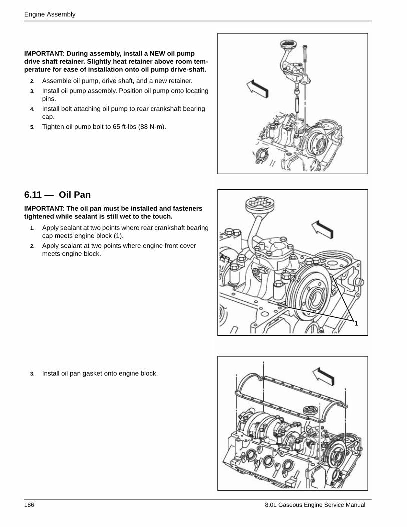
Engine Assembly
IMPORTANT: During assembly, install a NEW oil pump drive shaft retainer. Slightly heat retainer above room tem-perature for ease of installation onto oil pump drive-shaft.
2. Assemble oil pump, drive shaft, and a new retainer.
3. Install oil pump assembly. Position oil pump onto locating pins.
4. Install bolt attaching oil pump to rear crankshaft bearing cap.
5. Tighten oil pump bolt to 65 ft-lbs (88 N-m).
6.11 — Oil PanIMPORTANT: The oil pan must be installed and fasteners tightened while sealant is still wet to the touch.
1. Apply sealant at two points where rear crankshaft bearing cap meets engine block (1).
2. Apply sealant at two points where engine front cover meets engine block.
3. Install oil pan gasket onto engine block.
1
186 8.0L Gaseous Engine Service Manual
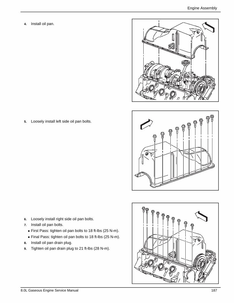
Engine Assembly
4. Install oil pan.
5. Loosely install left side oil pan bolts.
6. Loosely install right side oil pan bolts.
7. Install oil pan bolts.
• First Pass: tighten oil pan bolts to 18 ft-lbs (25 N-m).
• Final Pass: tighten oil pan bolts to 18 ft-lbs (25 N-m).
8. Install oil pan drain plug.
9. Tighten oil pan drain plug to 21 ft-lbs (28 N-m).
8.0L Gaseous Engine Service Manual 187
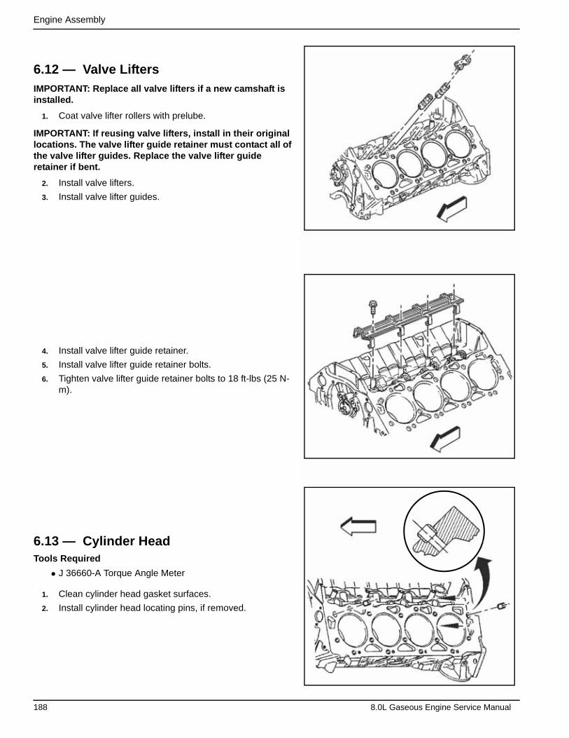
Engine Assembly
6.12 — Valve LiftersIMPORTANT: Replace all valve lifters if a new camshaft is installed.
1. Coat valve lifter rollers with prelube.
IMPORTANT: If reusing valve lifters, install in their original locations. The valve lifter guide retainer must contact all of the valve lifter guides. Replace the valve lifter guide retainer if bent.
2. Install valve lifters.
3. Install valve lifter guides.
4. Install valve lifter guide retainer.
5. Install valve lifter guide retainer bolts.
6. Tighten valve lifter guide retainer bolts to 18 ft-lbs (25 N-m).
6.13 — Cylinder HeadTools Required
• J 36660-A Torque Angle Meter
1. Clean cylinder head gasket surfaces.
2. Install cylinder head locating pins, if removed.
188 8.0L Gaseous Engine Service Manual
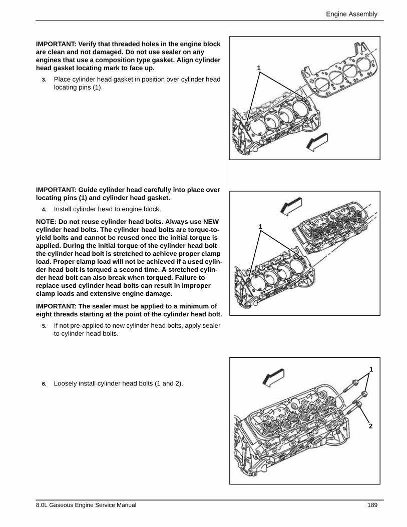
Engine Assembly
IMPORTANT: Verify that threaded holes in the engine block are clean and not damaged. Do not use sealer on any engines that use a composition type gasket. Align cylinder head gasket locating mark to face up.
3. Place cylinder head gasket in position over cylinder head locating pins (1).
IMPORTANT: Guide cylinder head carefully into place over locating pins (1) and cylinder head gasket.
4. Install cylinder head to engine block.
NOTE: Do not reuse cylinder head bolts. Always use NEW cylinder head bolts. The cylinder head bolts are torque-to-yield bolts and cannot be reused once the initial torque is applied. During the initial torque of the cylinder head bolt the cylinder head bolt is stretched to achieve proper clamp load. Proper clamp load will not be achieved if a used cylin-der head bolt is torqued a second time. A stretched cylin-der head bolt can also break when torqued. Failure to replace used cylinder head bolts can result in improper clamp loads and extensive engine damage.
IMPORTANT: The sealer must be applied to a minimum of eight threads starting at the point of the cylinder head bolt.
5. If not pre-applied to new cylinder head bolts, apply sealer to cylinder head bolts.
6. Loosely install cylinder head bolts (1 and 2).
1
1
1
2
8.0L Gaseous Engine Service Manual 189
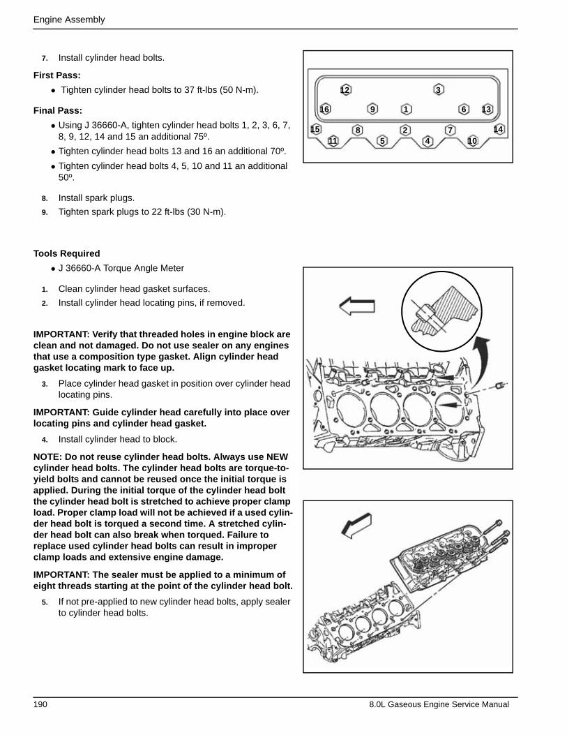
Engine Assembly
7. Install cylinder head bolts.
First Pass:
• Tighten cylinder head bolts to 37 ft-lbs (50 N-m).
Final Pass:
• Using J 36660-A, tighten cylinder head bolts 1, 2, 3, 6, 7, 8, 9, 12, 14 and 15 an additional 75º.
• Tighten cylinder head bolts 13 and 16 an additional 70º.
• Tighten cylinder head bolts 4, 5, 10 and 11 an additional 50º.
8. Install spark plugs.
9. Tighten spark plugs to 22 ft-lbs (30 N-m).
Tools Required
• J 36660-A Torque Angle Meter
1. Clean cylinder head gasket surfaces.
2. Install cylinder head locating pins, if removed.
IMPORTANT: Verify that threaded holes in engine block are clean and not damaged. Do not use sealer on any engines that use a composition type gasket. Align cylinder head gasket locating mark to face up.
3. Place cylinder head gasket in position over cylinder head locating pins.
IMPORTANT: Guide cylinder head carefully into place over locating pins and cylinder head gasket.
4. Install cylinder head to block.
NOTE: Do not reuse cylinder head bolts. Always use NEW cylinder head bolts. The cylinder head bolts are torque-to-yield bolts and cannot be reused once the initial torque is applied. During the initial torque of the cylinder head bolt the cylinder head bolt is stretched to achieve proper clamp load. Proper clamp load will not be achieved if a used cylin-der head bolt is torqued a second time. A stretched cylin-der head bolt can also break when torqued. Failure to replace used cylinder head bolts can result in improper clamp loads and extensive engine damage.
IMPORTANT: The sealer must be applied to a minimum of eight threads starting at the point of the cylinder head bolt.
5. If not pre-applied to new cylinder head bolts, apply sealer to cylinder head bolts.
1
2
3
45
6
78
9
1011
12
13
1415
16
190 8.0L Gaseous Engine Service Manual
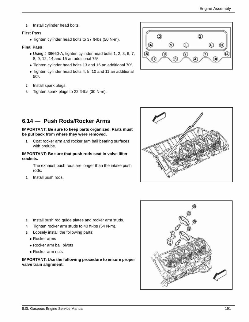
Engine Assembly
6. Install cylinder head bolts.
First Pass
• Tighten cylinder head bolts to 37 ft-lbs (50 N-m).
Final Pass
• Using J 36660-A, tighten cylinder head bolts 1, 2, 3, 6, 7, 8, 9, 12, 14 and 15 an additional 75º.
• Tighten cylinder head bolts 13 and 16 an additional 70º.
• Tighten cylinder head bolts 4, 5, 10 and 11 an additional 50º.
7. Install spark plugs.
8. Tighten spark plugs to 22 ft-lbs (30 N-m).
6.14 — Push Rods/Rocker ArmsIMPORTANT: Be sure to keep parts organized. Parts must be put back from where they were removed.
1. Coat rocker arm and rocker arm ball bearing surfaces with prelube.
IMPORTANT: Be sure that push rods seat in valve lifter sockets.
The exhaust push rods are longer than the intake push rods.
2. Install push rods.
3. Install push rod guide plates and rocker arm studs.
4. Tighten rocker arm studs to 40 ft-lbs (54 N-m).
5. Loosely install the following parts:
• Rocker arms
• Rocker arm ball pivots
• Rocker arm nuts
IMPORTANT: Use the following procedure to ensure proper valve train alignment.
1
2
3
45
6
78
9
1011
12
13
1415
16
8.0L Gaseous Engine Service Manual 191
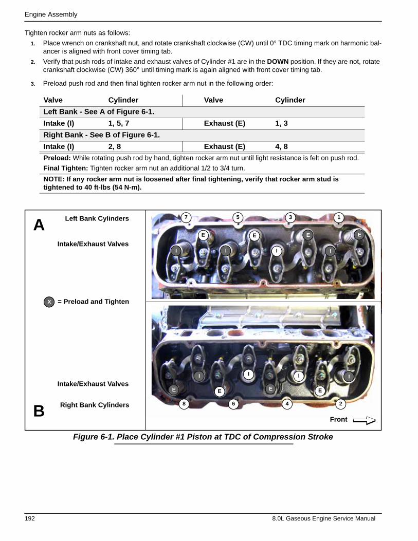
Engine Assembly
Tighten rocker arm nuts as follows:
1. Place wrench on crankshaft nut, and rotate crankshaft clockwise (CW) until 0° TDC timing mark on harmonic bal-ancer is aligned with front cover timing tab.
2. Verify that push rods of intake and exhaust valves of Cylinder #1 are in the DOWN position. If they are not, rotate crankshaft clockwise (CW) 360° until timing mark is again aligned with front cover timing tab.
3. Preload push rod and then final tighten rocker arm nut in the following order:
Figure 6-1. Place Cylinder #1 Piston at TDC of Compression Stroke
Valve Cylinder Valve Cylinder
Left Bank - See A of Figure 6-1.
Intake (I) 1, 5, 7 Exhaust (E) 1, 3
Right Bank - See B of Figure 6-1.
Intake (I) 2, 8 Exhaust (E) 4, 8
Preload: While rotating push rod by hand, tighten rocker arm nut until light resistance is felt on push rod.
Final Tighten: Tighten rocker arm nut an additional 1/2 to 3/4 turn.
NOTE: If any rocker arm nut is loosened after final tightening, verify that rocker arm stud is tightened to 40 ft-lbs (54 N-m).
ALeft Bank Cylinders
Intake/Exhaust Valves
Intake/Exhaust Valves
7 5 3 1
Right Bank Cylinders 8 6 4 2
E E
I
II
E
= Preload and Tighten
FrontB
I
E
I
E
I I
E E
X
I
E
192 8.0L Gaseous Engine Service Manual
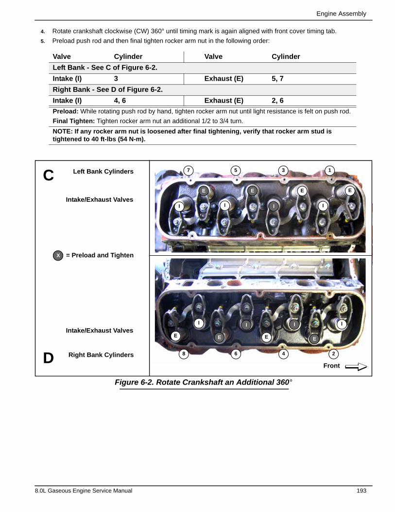
Engine Assembly
4. Rotate crankshaft clockwise (CW) 360° until timing mark is again aligned with front cover timing tab.
5. Preload push rod and then final tighten rocker arm nut in the following order:
Figure 6-2. Rotate Crankshaft an Additional 360°
Valve Cylinder Valve Cylinder
Left Bank - See C of Figure 6-2.
Intake (I) 3 Exhaust (E) 5, 7
Right Bank - See D of Figure 6-2.
Intake (I) 4, 6 Exhaust (E) 2, 6
Preload: While rotating push rod by hand, tighten rocker arm nut until light resistance is felt on push rod.
Final Tighten: Tighten rocker arm nut an additional 1/2 to 3/4 turn.
NOTE: If any rocker arm nut is loosened after final tightening, verify that rocker arm stud is tightened to 40 ft-lbs (54 N-m).
Front
7 5 3 1
8 6 4 2
Left Bank Cylinders
Intake/Exhaust Valves
Intake/Exhaust Valves
Right Bank Cylinders
E
II
E
E
I I
E
C
x = Preload and Tighten
D
E E
I
I I
E
X
I
E
8.0L Gaseous Engine Service Manual 193

Engine Assembly
6.3 — Splash Shield1. Install splash shield.
2. Ensure splash shield (2) snap fits between cylinder heads (1).
6.4 — Intake Manifold1. Install new intake manifold seals.
2. Install new intake manifold gaskets onto cylinder heads.
2
1
194 8.0L Gaseous Engine Service Manual

Engine Assembly
3. Verify that intake manifold gasket tabs (4) align with hole in head gasket (3).
4. Verify that intake manifold gasket tabs (1) align with slot in intake manifold seals (2).
5. Install intake manifold onto engine block.
6. Apply sealer to a minimum of eight threads of intake man-ifold bolts.
7. Install intake manifold bolts.
• First pass: tighten intake manifold bolts (1–8) in sequence to 22 ft-lbs (30 N-m).
• Final pass: tighten intake manifold bolts (1–8) in sequence to 30 ft-lbs (40 N-m).
15 11
16 12
5 1
8 2 4 6
13
14
97
3
10
4
1
2
3
8.0L Gaseous Engine Service Manual 195

Engine Assembly
6.5 — Distributor1. Install distributor.
NOTE: See Subsection 3.7 —Distributor.
6.6 — Rocker Arm CoverNOTE: This bolt is a self-tapping bolt. If installing this bolt into a new component, installation of the bolt may be diffi-cult. Ensure that bolt is not over-torqued during initial installation (thread cutting). Failure to limit torque can lead to bolt failure.
1. If rocker arm cover gasket was removed from rocker arm cover, install a new rocker arm cover gasket.
2. Install rocker arm cover with gasket.
196 8.0L Gaseous Engine Service Manual
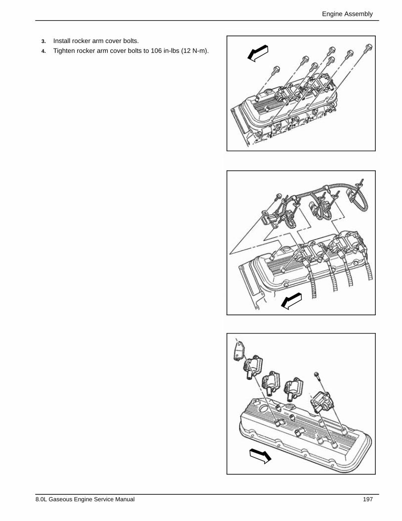
Engine Assembly
3. Install rocker arm cover bolts.
4. Tighten rocker arm cover bolts to 106 in-lbs (12 N-m).
8.0L Gaseous Engine Service Manual 197
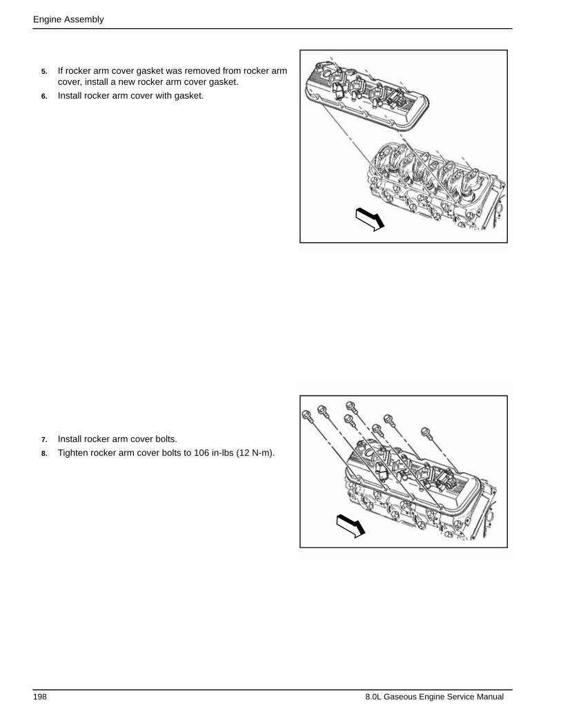
Engine Assembly
5. If rocker arm cover gasket was removed from rocker arm cover, install a new rocker arm cover gasket.
6. Install rocker arm cover with gasket.
7. Install rocker arm cover bolts.
8. Tighten rocker arm cover bolts to 106 in-lbs (12 N-m).
198 8.0L Gaseous Engine Service Manual

Engine Assembly
6.7 — Crankshaft BalancerTools Required
• J 23523-F Crankshaft Balancer Remover and Installer
NOTE: The inertial weight section of the crankshaft bal-ancer is assembled to the hub with a rubber type material. The correct installation procedures (with the proper tool) must be followed or movement of the inertial weight sec-tion of the hub will destroy the tuning of the crankshaft bal-ancer.
1. Apply a small amount of sealant onto crankshaft key and keyway to seal the balancer keyway and crankshaft joint.
2. Install key into crankshaft keyway.
3. Apply a small amount of sealant onto crankshaft balancer keyway (2) to seal the balancer keyway and crankshaft joint.
2.00 mm(0.07”)1.00 mm
(0.03”)
1
2
8.0L Gaseous Engine Service Manual 199
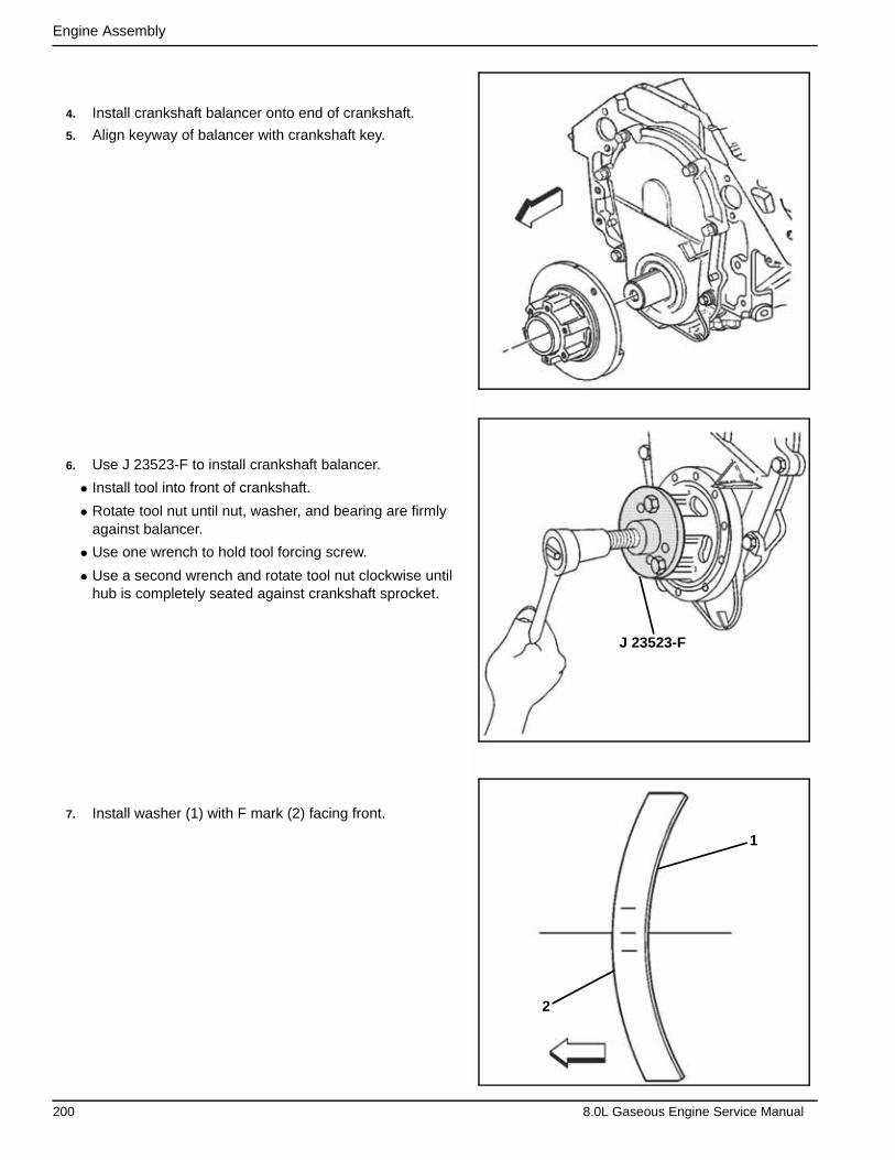
Engine Assembly
4. Install crankshaft balancer onto end of crankshaft.
5. Align keyway of balancer with crankshaft key.
6. Use J 23523-F to install crankshaft balancer.
• Install tool into front of crankshaft.
• Rotate tool nut until nut, washer, and bearing are firmly against balancer.
• Use one wrench to hold tool forcing screw.
• Use a second wrench and rotate tool nut clockwise until hub is completely seated against crankshaft sprocket.
7. Install washer (1) with F mark (2) facing front.
J 23523-F
1
2
200 8.0L Gaseous Engine Service Manual
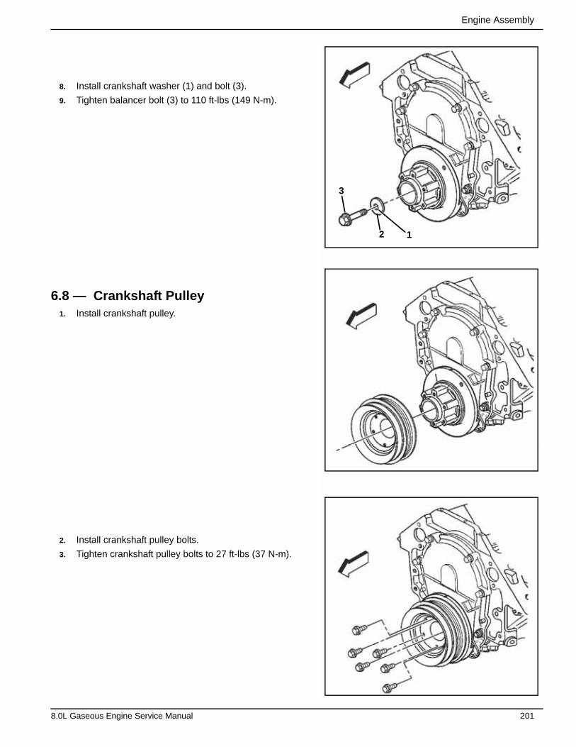
Engine Assembly
8. Install crankshaft washer (1) and bolt (3).
9. Tighten balancer bolt (3) to 110 ft-lbs (149 N-m).
6.8 — Crankshaft Pulley1. Install crankshaft pulley.
2. Install crankshaft pulley bolts.
3. Tighten crankshaft pulley bolts to 27 ft-lbs (37 N-m).
3
2 1
8.0L Gaseous Engine Service Manual 201
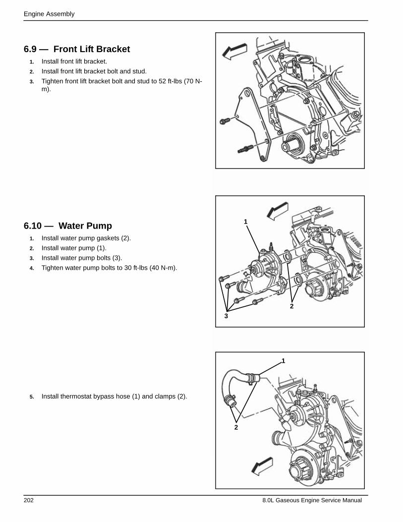
Engine Assembly
6.9 — Front Lift Bracket1. Install front lift bracket.
2. Install front lift bracket bolt and stud.
3. Tighten front lift bracket bolt and stud to 52 ft-lbs (70 N-m).
6.10 — Water Pump1. Install water pump gaskets (2).
2. Install water pump (1).
3. Install water pump bolts (3).
4. Tighten water pump bolts to 30 ft-lbs (40 N-m).
5. Install thermostat bypass hose (1) and clamps (2).
2
3
1
1
2
202 8.0L Gaseous Engine Service Manual
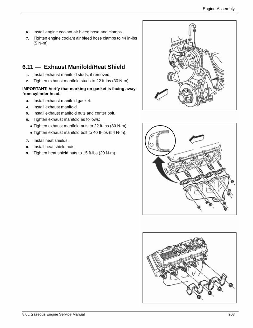
Engine Assembly
6. Install engine coolant air bleed hose and clamps.
7. Tighten engine coolant air bleed hose clamps to 44 in-lbs (5 N-m).
6.11 — Exhaust Manifold/Heat Shield1. Install exhaust manifold studs, if removed.
2. Tighten exhaust manifold studs to 22 ft-lbs (30 N-m).
IMPORTANT: Verify that marking on gasket is facing away from cylinder head.
3. Install exhaust manifold gasket.
4. Install exhaust manifold.
5. Install exhaust manifold nuts and center bolt.
6. Tighten exhaust manifold as follows:
• Tighten exhaust manifold nuts to 22 ft-lbs (30 N-m).
• Tighten exhaust manifold bolt to 40 ft-lbs (54 N-m).
7. Install heat shields.
8. Install heat shield nuts.
9. Tighten heat shield nuts to 15 ft-lbs (20 N-m).
8.0L Gaseous Engine Service Manual 203
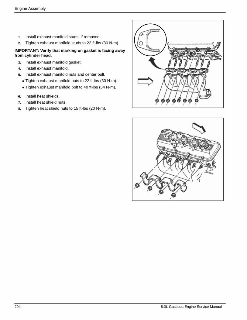
Engine Assembly
1. Install exhaust manifold studs, if removed.
2. Tighten exhaust manifold studs to 22 ft-lbs (30 N-m).
IMPORTANT: Verify that marking on gasket is facing away from cylinder head.
3. Install exhaust manifold gasket.
4. Install exhaust manifold.
5. Install exhaust manifold nuts and center bolt.
• Tighten exhaust manifold nuts to 22 ft-lbs (30 N-m).
• Tighten exhaust manifold bolt to 40 ft-lbs (54 N-m).
6. Install heat shields.
7. Install heat shield nuts.
8. Tighten heat shield nuts to 15 ft-lbs (20 N-m).
204 8.0L Gaseous Engine Service Manual

Engine Assembly
1. Install oil level indicator tube and new O-ring into oil pan.
2. Properly position oil level indicator tube and install bracket nut to right exhaust manifold stud.
3. Tighten oil level indicator tube nut to 40 ft-lbs (54 N-m).
4. Install oil level indicator tube retaining clip.
5. Install oil level indicator into oil level indicator tube.
6. To prevent rubbing, verify correct orientation of the follow-ing:
• Spark plug wires
• Coolant hoses
IMPORTANT: Install bearing from crankshaft side of fly-wheel.
1. Install new clutch pilot bearing (1) flush with surface of crankshaft flange bore (2).
2. Verify proper installation.
CAUTION: Wear safety glasses to avoid eye injury.
1
2
*
8.0L Gaseous Engine Service Manual 205
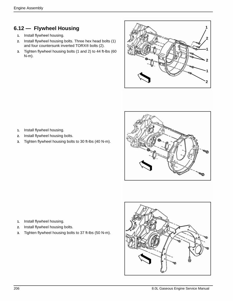
Engine Assembly
6.12 — Flywheel Housing1. Install flywheel housing.
2. Install flywheel housing bolts. Three hex head bolts (1) and four countersunk inverted TORX® bolts (2).
3. Tighten flywheel housing bolts (1 and 2) to 44 ft-lbs (60 N-m).
1. Install flywheel housing.
2. Install flywheel housing bolts.
3. Tighten flywheel housing bolts to 30 ft-lbs (40 N-m).
1. Install flywheel housing.
2. Install flywheel housing bolts.
3. Tighten flywheel housing bolts to 37 ft-lbs (50 N-m).
2
2
2
1
1
1
206 8.0L Gaseous Engine Service Manual
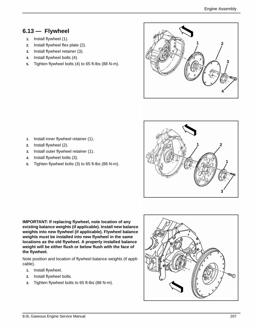
Engine Assembly
6.13 — Flywheel1. Install flywheel (1).
2. Install flywheel flex plate (2).
3. Install flywheel retainer (3).
4. Install flywheel bolts (4).
5. Tighten flywheel bolts (4) to 65 ft-lbs (88 N-m).
1. Install inner flywheel retainer (1).
2. Install flywheel (2).
3. Install outer flywheel retainer (1).
4. Install flywheel bolts (3).
5. Tighten flywheel bolts (3) to 65 ft-lbs (88 N-m).
IMPORTANT: If replacing flywheel, note location of any existing balance weights (if applicable). Install new balance weights into new flywheel (if applicable). Flywheel balance weights must be installed into new flywheel in the same locations as the old flywheel. A properly installed balance weight will be either flush or below flush with the face of the flywheel.
Note position and location of flywheel balance weights (if appli-cable).
1. Install flywheel.
2. Install flywheel bolts.
3. Tighten flywheel bolts to 65 ft-lbs (88 N-m).
1 2
3
4
1
1
2
3
8.0L Gaseous Engine Service Manual 207
Engine Assembly
This page intentionally left blank.
208 8.0L Gaseous Engine Service Manual

Section 7 Tools, Methods and Materials
7.1 — Parts Description
7.1.1— Cylinder Block
The engine block is made of cast iron and it has eight cylinders arranged in a V shape with four cylinders in each bank. The engine block is a one piece casting with the cylinders encircled by coolant jackets.
7.1.2— Cylinder Head
The cylinder heads are made of cast iron and have parent metal intake valve guides and intake valve seats. The cast iron exhaust valve guides and powdered metal valve seats are pressed into the exhaust ports. A spark plug is located between the valves in the side of the cylinder head.
8.0L Gaseous Engine Service Manual 209
Tools, Methods and Materials
7.1.3— Camshaft
A steel camshaft is supported by five bearings pressed into the engine block. The camshaft sprocket is mounted to the front of the camshaft and is driven by the crankshaft sprocket through a camshaft timing chain.
Motion from the camshaft is transmitted to the valves by hydraulic roller valve lifters, valve pushrods, and ball-pivot type rocker arms. A spiral gear machined into the camshaft near the rear journal drives a shaft assembly which operates the oil pump driveshaft assembly.
7.1.4— Crankshaft
The crankshaft is made of cast nodular iron. The crankshaft is supported by five crankshaft bearings. The crankshaft bearings are retained by the crankshaft bearing caps. The crankshaft bearing caps are machined with the engine block for proper alignment and clearance. The engine crankshaft bearing caps are retained by four bolts each. The number five crankshaft bearing at the rear of the engine block is the end thrust bearing. The four connecting rod journals (two rods per journal) are spaced 90º apart.
The crankshaft position sensor reluctor ring is pushed onto the front of the crankshaft.
7.1.5— Pistons and Connecting Rods
The pistons are cast aluminum alloy that use two compression rings and one oil control ring assembly. The piston pins are a floating fit in the pistons and the piston pins are retained by a press fit in the connecting rod assembly. The con-necting rods are forged steel and have precision insert type crankpin bearings.
7.1.6— Valve Train
The valve train is a ball pivot type. Motion is transmitted from the camshaft through the hydraulic roller valve lifters and tubular valve pushrods to the valve rocker arms. The valve rocker arm pivots on a ball to open the valve. The hydraulic roller valve lifters keep all parts of the valve train in constant contact. Each valve lifter act as an automatic adjuster and maintains zero lash in the valve train. This eliminates the need for periodic valve adjustment. The valve rocker arm bolt retains the valve rocker arm and ball seat. The valve rocker arm bolt is threaded into the cylinder head.
7.1.7— Intake Manifold
The intake manifold is a one-piece design. The throttle body is attached to the intake manifold.
7.1.8— Exhaust Manifold
The two exhaust manifolds are constructed of cast iron. The exhaust manifolds direct exhaust gases from the combus-tion chambers to the exhaust system.
7.1.9— Drive Belt
The drive belt system consists of the following components:
• The drive belt
• The drive belt tensioner
• The drive belt idler pulley
• The crankshaft balancer pulley
• The accessory drive component mounting brackets
• The accessory drive components
– The generator
– The engine cooling fan, if belt driven
– The water pump, if belt driven
210 8.0L Gaseous Engine Service Manual
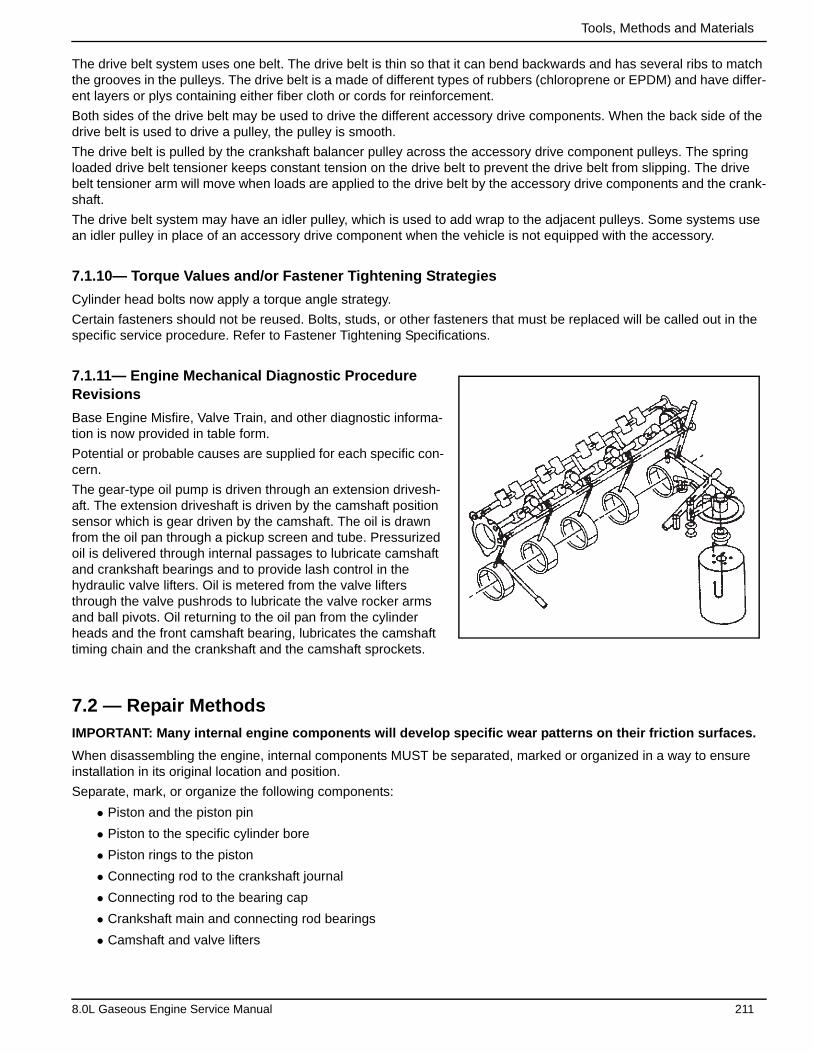
Tools, Methods and Materials
The drive belt system uses one belt. The drive belt is thin so that it can bend backwards and has several ribs to match the grooves in the pulleys. The drive belt is a made of different types of rubbers (chloroprene or EPDM) and have differ-ent layers or plys containing either fiber cloth or cords for reinforcement.
Both sides of the drive belt may be used to drive the different accessory drive components. When the back side of the drive belt is used to drive a pulley, the pulley is smooth.
The drive belt is pulled by the crankshaft balancer pulley across the accessory drive component pulleys. The spring loaded drive belt tensioner keeps constant tension on the drive belt to prevent the drive belt from slipping. The drive belt tensioner arm will move when loads are applied to the drive belt by the accessory drive components and the crank-shaft.
The drive belt system may have an idler pulley, which is used to add wrap to the adjacent pulleys. Some systems use an idler pulley in place of an accessory drive component when the vehicle is not equipped with the accessory.
7.1.10— Torque Values and/or Fastener Tightening Strategies
Cylinder head bolts now apply a torque angle strategy.
Certain fasteners should not be reused. Bolts, studs, or other fasteners that must be replaced will be called out in the specific service procedure. Refer to Fastener Tightening Specifications.
7.1.11— Engine Mechanical Diagnostic Procedure Revisions
Base Engine Misfire, Valve Train, and other diagnostic informa-tion is now provided in table form.
Potential or probable causes are supplied for each specific con-cern.
The gear-type oil pump is driven through an extension drivesh-aft. The extension driveshaft is driven by the camshaft position sensor which is gear driven by the camshaft. The oil is drawn from the oil pan through a pickup screen and tube. Pressurized oil is delivered through internal passages to lubricate camshaft and crankshaft bearings and to provide lash control in the hydraulic valve lifters. Oil is metered from the valve lifters through the valve pushrods to lubricate the valve rocker arms and ball pivots. Oil returning to the oil pan from the cylinder heads and the front camshaft bearing, lubricates the camshaft timing chain and the crankshaft and the camshaft sprockets.
7.2 — Repair MethodsIMPORTANT: Many internal engine components will develop specific wear patterns on their friction surfaces.
When disassembling the engine, internal components MUST be separated, marked or organized in a way to ensure installation in its original location and position.
Separate, mark, or organize the following components:
• Piston and the piston pin
• Piston to the specific cylinder bore
• Piston rings to the piston
• Connecting rod to the crankshaft journal
• Connecting rod to the bearing cap
• Crankshaft main and connecting rod bearings
• Camshaft and valve lifters
8.0L Gaseous Engine Service Manual 211
Tools, Methods and Materials
• Valve lifters, guides, pushrods, pivot supports and rocker arms
• Valve to the valve guide
• Valve spring and shim to the cylinder head location
• Engine block main bearing cap location and direction
• Oil pump drive and driven gears
Throughout this section, it should be understood that proper cleaning and protection of machined surfaces and friction areas is part of the repair procedure. This is considered standard shop practice even if not specifically stated.
When any internal engine parts are serviced, care and cleanliness is important.
When components are removed for service, they should be marked, organized or retained in a specific order for reas-sembly.
At the time of installation, components should be installed in the same location and with the same mating surface as when removed.
An engine is a combination of many machined, honed, polished and lapped surfaces with tolerances that are measured in millimeters or thousandths of an inch. These surfaces should be covered or protected to avoid component damage.
A liberal coating of clean engine oil should be applied to friction areas during assembly.
Proper lubrication will protect and lubricate friction surfaces during initial operation.
7.2.1— Gasket Reuse and Applying Sealant
• Do not reuse any gasket unless specified.
• Gaskets that can be reused will be identified in the service procedure.
• Do not apply sealant to any gasket or sealing surface unless specified in the service procedure.
7.2.2— Separating Components
• Use a rubber mallet to separate the components.
• Bump the part sideways to loosen the components.
• Bumping of the component should be done at bends or reinforced areas of the component to prevent distortion of the components.
7.2.3— Cleaning Gasket Surfaces
• Use care to avoid gouging or scraping the sealing surfaces.
• Use a plastic or wood scraper to remove all the sealant from the components.
• Do not use any other method or technique to remove the sealant or the gasket material from a part.
• Do not use abrasive pads, sand paper, or power tools to clean the gasket surfaces.
– These methods of cleaning can cause damage to the component sealing surfaces.
– Abrasive pads also produce a fine grit that the oil filter cannot remove from the engine oil. This fine grit is an abrasive and can cause internal engine damage.
7.2.4— Assembling Components
• Assemble components using only the sealant (or equivalent) that is specified in the service procedure.
• Sealing surfaces must be clean and free of debris or oil.
• Specific components such as crankshaft oil seals or valve stem oil seals may require lubrication during assembly.
• Components requiring lubrication will be identified in the service procedure.
• Apply only the amount of sealant specified in the service procedure to a component.
212 8.0L Gaseous Engine Service Manual
Tools, Methods and Materials
• Do not allow the sealant to enter into any blind threaded holes, as the sealant may prevent the fastener from clamping properly or cause component damage when tightened.
IMPORTANT: Do not overtighten the fasteners.
• Tighten the fasteners to the proper specifications.
7.3 — Tools and Materials
7.3.1— Sealant Types
IMPORTANT: The correct sealant and amount of sealant must be used in the proper location to prevent oil leaks, coolant leaks, or the loosening of the fasteners.
DO NOT interchange the sealants. Use only the sealant, or equivalent, as specified in the service procedure.
The following 2 major types of sealant are commonly used in engines:
• Aerobic sealant Room Temperature Vulcanizing (RTV)
• Anaerobic sealant, which include the following:
– Gasket eliminator
– Pipe
– Threadlock
7.3.2— Aerobic Type Room Temperature Vulcanizing (RTV) Sealant
Aerobic type Room Temperature Vulcanizing (RTV) sealant cures when exposed to air. This type of sealant is used where 2 components, such as the intake manifold and the engine block, are assembled together.
Use the following information when using RTV sealant:
• Do not use RTV sealant in areas where extreme temperatures are expected. These areas include:
– The exhaust manifold
– The head gasket
– Any other surfaces where a different type of sealant is specified in the service procedure
• Always follow all the safety recommendations and the directions that are on the RTV sealant container.
• Use a plastic or wood scraper to remove all the RTV sealant from the components.
NOTE: Do not allow the RTV sealant to enter any blind threaded hole. RTV sealant that is allowed to enter a blind threaded hole can cause hydraulic lock of the fastener when the fastener is tightened. Hydraulic lock of a fastener can lead to damage to the fastener and/or the components. Hydraulic lock of a fastener can also pre-vent the proper clamping loads to be obtained when the fastener is tightened. Improper clamping loads can prevent proper sealing of the components allowing leakage to occur. Preventing proper fastener tightening can allow the components to loosen or separate leading to extensive engine damage.
• The surfaces to be sealed must be clean and dry.
• Use a RTV sealant bead size as specified in the service procedure.
• Apply the RTV sealant bead to the inside of any bolt holes areas.
IMPORTANT: Do not wait for the RTV sealant to skin over.
• Assemble the components while the RTV sealant is still wet to the touch, within 3 minutes.
IMPORTANT: Do not overtighten the fasteners.
• Tighten the fasteners in sequence, if specified, and to the proper torque specifications.
8.0L Gaseous Engine Service Manual 213
Tools, Methods and Materials
7.3.3— Anaerobic Type Gasket Eliminator Sealant
Anaerobic type gasket eliminator sealant cures in the absence of air. This type of sealant is used where 2 rigid parts, such as castings, are assembled together. When 2 rigid parts are disassembled and no sealant or gasket is readily noticeable, then the 2 parts were probably assembled using an anaerobic type gasket eliminator sealant.
Use the following information when using gasket eliminator sealant:
• Always follow all the safety recommendations and directions that are on the gasket eliminator sealant container.
• Apply a continuous bead of gasket eliminator sealant to one flange.
• The surfaces to be sealed must be clean and dry.
IMPORTANT:
• Do not allow the gasket eliminator sealant to enter any blind threaded holes, as the gasket eliminator sealant may prevent the fasteners from clamping properly, seating properly, or cause damage when the fastener tight-ened.
• Gasket eliminator sealed joint fasteners that are partially torqued and the gasket eliminator sealant allowed to cure more than five minutes, may result in incorrect shimming and sealing of the joint.
• Do not overtighten the fasteners.
– Apply the gasket eliminator sealant evenly to get a uniform thickness of the gasket eliminator sealant on the sealing surface.
– Tighten the fasteners in sequence, if specified, and to the proper torque specifications.
– After properly tightening the fasteners, remove the excess gasket eliminator sealant from the outside of the joint.
7.3.4— Anaerobic Type Threadlock Sealant
Anaerobic type threadlock sealant cures in the absence of air. This type of sealant is used for threadlocking and sealing of bolts, fittings, nuts, and studs. This type of sealant cures only when confined between 2 close fitting metal surfaces.
Use the following information when using threadlock sealant:
• Always follow all safety recommendations and directions that are on the threadlock sealant container.
• The threaded surfaces to be sealed must be clean and dry.
• Apply the threadlock sealant as specified on the threadlock sealant container.
IMPORTANT:
• Fasteners that are partially torqued and then the threadlock sealant allowed to cure more than five minutes, may result in incorrect clamp load of assembled components.
• Do not overtighten the fasteners.
• Tighten the fasteners in sequence, if specified, and to the proper torque specifications.
7.3.5— Anaerobic Type Pipe Sealant
Anaerobic type pipe sealant cures in the absence of air and remains pliable when cured. This type of sealant is used where 2 parts are assembled together and require a leak proof joint.
Use the following information when using pipe sealant:
• Do not use pipe sealant in areas where extreme temperatures are expected. These areas include:
– The exhaust manifold
– The head gasket
– Surfaces where a different sealant is specified
• Always follow all the safety recommendations and the directions that are on the pipe sealant container.
• The surfaces to be sealed must be clean and dry.
• Use a pipe sealant bead of the size or quantity as specified in the service procedure.
214 8.0L Gaseous Engine Service Manual
Tools, Methods and Materials
NOTE: Do not allow the pipe sealant to enter a blind hole. The pipe sealant may prevent the fastener from achieving proper clamp load, cause component damage when the fastener is tightened, or lead to component failure.
• Apply the pipe sealant bead to the inside of any bolt hole areas.
• Apply a continuous bead of pipe sealant to 1 sealing surface.
IMPORTANT: Do not overtighten the fasteners.
• Tighten the fasteners in sequence, if specified, and to the proper torque specifications.
• Special tools are listed and illustrated throughout this section with a complete listing at the end of the section. These tools (or their equivalents) are specially designed to quickly and safely accomplish the operations for which they are intended. The use of these special tools will also minimize possible damage to engine compo-nents. Some precision measuring tools are required for inspection of certain critical components. Torque wrenches and a torque angle meter are necessary for the proper tightening of various fasteners.
• To properly service the engine assembly, the following items should be readily available:
– Approved eye protection and safety gloves
– A clean, well-lit, work area
– A suitable parts cleaning tank
– A compressed air supply
– Trays or storage containers to keep parts and fasteners organized
– An adequate set of hand tools
– Approved engine repair stand
– An approved engine lifting device that will adequately support the weight of the components
7.3.6— Tools and Equipment
Use of special tools are described and illustrated throughout this manual with a complete listing at the end of this sec-tion. These tools (or their equivalents) are specially designed to quickly and safely accomplish the operations for which they are intended. The use of these special tools will also minimize possible damage to engine components. Some precision measuring tools are required for inspection of certain critical components. Torque wrenches and a torque angle meter are necessary for the proper tightening of certain fasteners.
To properly service the engine assembly, the following items should be readily available:
• Approved eye protection and safety gloves
• A clean, well-lit, work area
• A suitable parts cleaning tank
• A compressed air supply
• Trays or storage containers to keep parts and fasteners organized
• An adequate set of hand tools
• Approved engine repair stand
• An approved engine lifting device that will adequately support the weight of the components
8.0L Gaseous Engine Service Manual 215
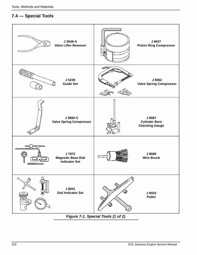
Tools, Methods and Materials
7.4 — Special Tools
Figure 7-1. Special Tools (1 of 2)
J 3049-AValve Lifter Remover
J 5239Guide Set
J 5892-CValve Spring Compressor
J 7872Magnetic Base Dial
Indicator Set
J 8001Dial Indicator Set
J 8037Piston Ring Compressor
J 8062Valve Spring Compressor
J 8087Cylinder Bore
Checking Gauge
J 8089Wire Brush
J 8433Puller
216 8.0L Gaseous Engine Service Manual

Tools, Methods and Materials
Figure 7-2. Special Tools (2 of 2)
J 9666Valve Spring Tester
J 21882Oil Suction Pipe
Installer
J 22102Front Cover Oil Seal
Installer
J 22794Spark Plug Port
Adapter
J 24086-CPiston Pin
Remover and Installer Set
J 24270Ridge Reamer
J 25254-10Oil Pressure Sending
Unit Socket
J 33049Camshaft BearingRemover/Installer
J 36857Engine Lift Bracket
J 38841Rear Main Seal
Installer
8.0L Gaseous Engine Service Manual 217

Part No. 0K7681ASMNLY09 Rev. A 12/02/2014 Printed in USA