periodic verification guide for traffic signals, road .../media/busind/techstdpubs/traffic...
TRANSCRIPT

Manual Traffic and Road Use Management Volume 4 – Intelligent Transport Systems and Electrical Technology Part 6: Periodic Verification Guide for Traffic Signals, Road Lights and ITS Equipment Installations November 2017

Traffic and Road Use Management, Transport and Main Roads, November 2017
Copyright
http://creativecommons.org/licenses/by/3.0/au/
© State of Queensland (Department of Transport and Main Roads) 2017
Feedback: Please send your feedback regarding this document to: [email protected]

Traffic and Road Use Management, Transport and Main Roads, November 2017 i
Contents
1 Introduction ....................................................................................................................................1
2 References ......................................................................................................................................1
3 Legislation and Standards ............................................................................................................2
4 Methodology ...................................................................................................................................2
5 Terminology ...................................................................................................................................3
5.1 MEN (Multiple Earthed Neutral) system ......................................................................................... 3
5.2 Protective and Functional Earthing ................................................................................................. 3
6 Traffic signals and road lighting ..................................................................................................3
6.1 Electrical components ..................................................................................................................... 3
6.2 Equipment configuration ................................................................................................................. 3 6.2.1 Traffic signals .................................................................................................................3 6.2.2 Road lights (park, pathway and pedestrian tunnels) ......................................................4
7 Testing requirements ....................................................................................................................5
7.1 Pre start tests .................................................................................................................................. 5
7.2 Risk assessment procedure ........................................................................................................... 5
7.3 Electrical risk in departmental infrastructure ................................................................................... 5
7.4 Test equipment ............................................................................................................................... 6
7.5 Test sequence ................................................................................................................................ 6
8 Electrical tests ................................................................................................................................7
8.1 Test equipment (typical) ................................................................................................................. 8
8.2 Test requirements ......................................................................................................................... 10 8.2.1 Visual ........................................................................................................................... 10 8.2.2 Earth continuity ............................................................................................................ 10 8.2.3 Neutral integrity ........................................................................................................... 10 8.2.4 Main earth conductor resistance ................................................................................. 10 8.2.5 Insulation resistance .................................................................................................... 10 8.2.6 Polarity ......................................................................................................................... 10 8.2.7 Correct circuit connections .......................................................................................... 10 8.2.8 Earth Fault Loop Impedance ....................................................................................... 11 8.2.9 Verification of Residual Current Device ...................................................................... 12 8.2.10 Infrared thermal imaging ............................................................................................. 12 8.2.11 Touch voltage testing .................................................................................................. 13
Appendix A: Test procedure – traffic signals (energised) .............................................................. 14
Appendix B: Test procedure – road lighting (de-energised where possible) ............................... 18
Appendix C: Test procedure – road lighting (circuits energised) .................................................. 22
Appendix D: Result Sheet – traffic signals (energised) .................................................................. 25
Appendix E: Result Sheet – road lighting ......................................................................................... 26
Appendix F: Result sheet – road lighting ......................................................................................... 27

Volume 4: Part 6 – Periodic Verification Guide for Traffic Signals, Road Lights and ITS Equipment Installations
Traffic and Road Use Management, Transport and Main Roads, November 2017 1
1 Introduction
It is a Queensland legislative requirement, under the Electrical Safety Act 2002 and AS/NZS 3000:2007 (known as Wiring Rules) (as amended), that electrical installations are installed and maintained to be electrically safe and fit for purpose.
To achieve this, periodic electrical verification of installations is required to be completed on traffic signals, road lights and Intelligent Transport Systems (ITS) equipment.
Traffic signals and road lighting compliance to the Wiring Rules is via specific design and installation, therefore the generic testing regime specified for periodic verification cannot be directly implemented. To minimise effects on the asset and to provide an economical solution, only visual inspection and limited testing is recommended. This document details the recommended applicable tests. The procedures detailed within Appendices A – C are a guide only and alternative procedures can be specified by the region with consideration to local conditions and requirements.
Due to the vast array of ITS equipment types, models, variations, etc., it is not possible to define a ‘standard’ testing regime to cover all ITS equipment. All testing on ITS equipment shall be in accordance with the manufacturer’s recommendations (if not available, confirm testing will not affect any sensitive equipment) and in accordance with associated legislation and standards.
2 References
Below is a list of Standard Drawings and documents for reference.
Vendor data shall be referred to where applicable.
Reference Title
Figure A Traffic signal (energised)
Figure B and Figure C Road lighting (de-energised)
Figure D and Figure E Road lighting (energised)
RMPC Road Maintenance Performance Contract
SD1329 Road lighting – Typical physical arrangement
SD1399 Road lighting – Base plate mounted pole wiring details
SD1407 Traffic signals – Traffic signal terminal panel for joint use poles
SD1420 Traffic signals – General arrangements
SD1423 Traffic signals – Traffic signal controller base installation details
SD1430 Road lighting – Switchboard pillar mounted
SD1623 Road lighting – Switchboard typical layout and circuit diagram MEN system
SD1624 Road lighting — junction box single phase wiring details
SD1625 Road lighting — junction box three phase wiring details
SD1626 Road lighting — junction box active, neutral and earth bolting arrangements
SD1628 Road lighting — Post — Top-mounted switchboard
SD1670 Traffic signals – Traffic signal wiring connections
SD1676 Road lighting — Switchboard typical pillar layout

Volume 4: Part 6 – Periodic Verification Guide for Traffic Signals, Road Lights and ITS Equipment Installations
Traffic and Road Use Management, Transport and Main Roads, November 2017 2
Reference Title
SD1679 ITS – Telecommunications field cabinet base installation details
SD1699 Traffic signals/Road lighting/ITS – Parts list
TRUM Traffic and Road Use Management (TRUM) manual, Volume 4 – Intelligent Transport Systems and Electrical Technology, Part 3: Electrical Design for Roadside Devices
3 Legislation and Standards
The following Australian Standards and Regulatory Acts shall be referenced.
Reference Title
- Electrical Safety Regulation 2013 (Queensland)
- Electrical Safety Act 2002 (Queensland)
- Managing Electrical Risk in the Workplace – Code of Practice – Safe Work Australia
AS 2578:2009 Traffic signal controllers
AS/NZS 3000:2007 Electrical installations (known as Wiring Rules)
AS/NZS 3017:2007 Electrical installations – Verification guidelines
AS/NZS 3019:2007 Electrical installations – Periodic verification
AS/NZS 3947.3:2001 Low-voltage switchgear and controlgear – Switches, disconnectors, switch-disconnectors and fuse-combination units
AS/NZS 4836:2011 Safe working on or near low-voltage electrical installations and equipment
AS/NZS 5000.1:2005 Electric cables – Polymeric insulated – For working voltages up to and including 0.6/1 (1.2) kV
AS/NZS 5000.2:2006 Electric cables – Polymeric insulated – For working voltages up to and including 450/750 V
AS/NZS ISO 31000:2009 Risk management – Principles and guidelines
AS 61010 Safety requirements for electrical equipment for measurement, control and laboratory use.
AS 60269:2005 Low voltage fuses
AS/NZS 60529:2004 Degrees of protection provided by enclosures (IP code)
AS 60947.4.1–2004 Low-voltage switchgear and controlgear – Contactors and motor-starters – Electromechanical contactors and motor-starters
4 Methodology
A risk assessment will determine what traffic management plan will be implemented.
All testing shall be conducted in a de-energised state unless working live is permitted in the Electrical Safety Regulation 2013 (Queensland).
All work shall be completed by a competent person who is suitably qualified (whether by experience, training or both) to carry out the work or function.

Volume 4: Part 6 – Periodic Verification Guide for Traffic Signals, Road Lights and ITS Equipment Installations
Traffic and Road Use Management, Transport and Main Roads, November 2017 3
Prior to commencement of any work on an energised installation, a safe work method statement must be prepared as per the Electrical Safety Regulation 2013 (Queensland).
Periodic verification test procedures include:
• traffic signals
• road lighting.
5 Terminology
5.1 MEN (Multiple Earthed Neutral) system
The MEN system has the neutral of the distribution system earthed at the source of supply, at regular intervals throughout the system and at each electrical installation connected to the system.
If the MEN link was not in place during normal operation, the return fault current would be via ground. The impedance of the ground is generally much higher than the MEN/Protective Earth Neutral (PEN) conductor path. This would limit the magnitude of the fault current to a value which may be insufficient to cause the protective device to operate. If the protective device were not to operate, a life threatening voltage may remain on the metallic enclosure of the appliance or equipment.
5.2 Protective and Functional Earthing
The Protective Earthing (PE) conductor includes all earthing conductors (excluding the main earthing conductor and the functional earth) and is required to have sufficiently low resistance to permit adequate fault current to flow to earth and cause the protection device to operate.
A Functional Earth (FE) is provided for the purpose of correct operation, rather than safety. Such functional earthing conductors are not required to be selected and installed to withstand fault currents or to be identified in the same manner as a protective earthing conductor.
Note that a protective earth is always installed in addition to the functional earth.
6 Traffic signals and road lighting
6.1 Electrical components
Refer to the department’s SD1699 Traffic signals/Road lighting/ITS – Parts list, which provides details of standard electrical equipment items.
6.2 Equipment configuration
Details follow of equipment configurations for traffic signals and road lighting equipment.
6.2.1 Traffic signals
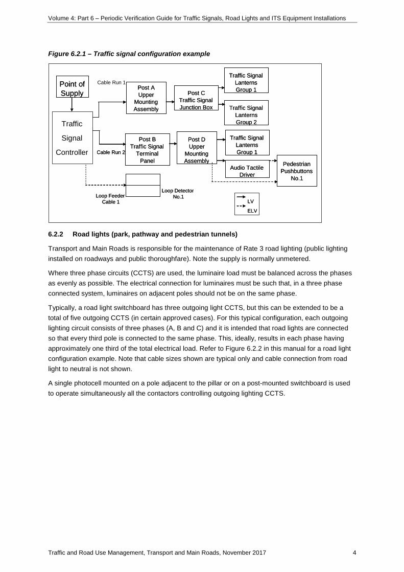
Transport and Main Roads traffic signals consist of a number of major components as shown in Figure 6.2.1 in this manual. Note the supply is typically unmetered.
Currently, there are three types of field terminals, which are: upper-mounting assembly terminal (for traffic signal post), traffic signal terminal panel (for joint-use pole) and traffic signal junction box (for mast arm).
Testing on Traffic Signal Controllers (TSC) shall be as per manufacturer’s requirements.
Volume 4: Part 6 – Periodic Verification Guide for Traffic Signals, Road Lights and ITS Equipment Installations
Traffic and Road Use Management, Transport and Main Roads, November 2017 4
Figure 6.2.1 – Traffic signal configuration example
6.2.2 Road lights (park, pathway and pedestrian tunnels)
Transport and Main Roads is responsible for the maintenance of Rate 3 road lighting (public lighting installed on roadways and public thoroughfare). Note the supply is normally unmetered.
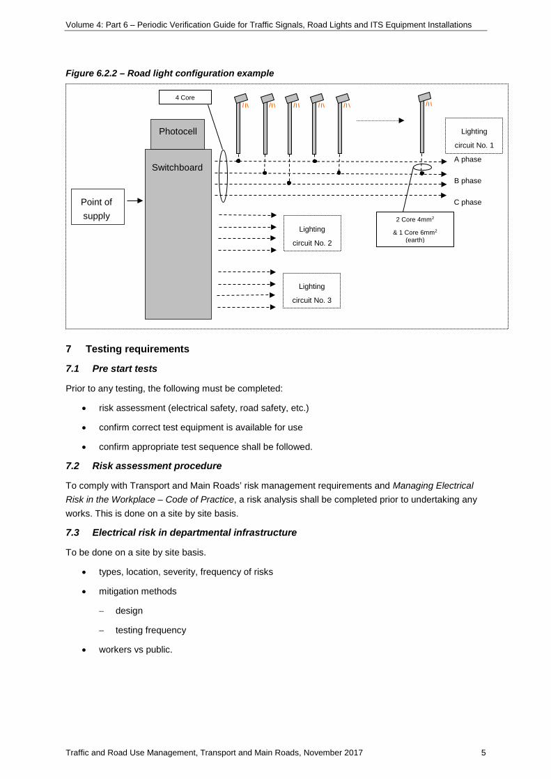
Where three phase circuits (CCTS) are used, the luminaire load must be balanced across the phases as evenly as possible. The electrical connection for luminaires must be such that, in a three phase connected system, luminaires on adjacent poles should not be on the same phase.
Typically, a road light switchboard has three outgoing light CCTS, but this can be extended to be a total of five outgoing CCTS (in certain approved cases). For this typical configuration, each outgoing lighting circuit consists of three phases (A, B and C) and it is intended that road lights are connected so that every third pole is connected to the same phase. This, ideally, results in each phase having approximately one third of the total electrical load. Refer to Figure 6.2.2 in this manual for a road light configuration example. Note that cable sizes shown are typical only and cable connection from road light to neutral is not shown.
A single photocell mounted on a pole adjacent to the pillar or on a post-mounted switchboard is used to operate simultaneously all the contactors controlling outgoing lighting CCTS.
Point of Supply
Post A Upper
Mounting Assembly
Post C Traffic Signal Junction Box
Post D Upper
Mounting Assembly
Traffic Signal Lanterns Group 1
Traffic Signal Lanterns Group 1
Traffic Signal Lanterns Group 2
Audio Tactile Driver
Pedestrian Pushbuttons
No.1
Loop Feeder Cable 1
Loop Detector No.1
Cable Run 2
Post B Traffic Signal
Terminal Panel
LV ELV
Point of Supply
Traffic
Signal
Controller
Post A Upper
Mounting Assembly
Post C Traffic Signal Junction Box
Post D Upper
Mounting Assembly
Traffic Signal Lanterns Group 1
Traffic Signal Lanterns Group 1
Traffic Signal Lanterns Group 2
Audio Tactile Driver
Pedestrian Pushbuttons
No.1
Cable Run 1
Loop Feeder Cable 1
Loop Detector No.1
Cable Run 2
Post B Traffic Signal
Terminal Panel
LV ELV
Volume 4: Part 6 – Periodic Verification Guide for Traffic Signals, Road Lights and ITS Equipment Installations
Traffic and Road Use Management, Transport and Main Roads, November 2017 5
Figure 6.2.2 – Road light configuration example
7 Testing requirements
7.1 Pre start tests
Prior to any testing, the following must be completed:
• risk assessment (electrical safety, road safety, etc.)
• confirm correct test equipment is available for use
• confirm appropriate test sequence shall be followed.
7.2 Risk assessment procedure
To comply with Transport and Main Roads’ risk management requirements and Managing Electrical Risk in the Workplace – Code of Practice, a risk analysis shall be completed prior to undertaking any works. This is done on a site by site basis.
7.3 Electrical risk in departmental infrastructure
To be done on a site by site basis.
• types, location, severity, frequency of risks
• mitigation methods
− design
− testing frequency
• workers vs public.
Point of supply
Switchboard A phase
B phase
C phase
Lighting
circuit No. 2
Lighting
circuit No. 3
Photocell Lighting
circuit No. 1
4 Core
2 Core 4mm2
& 1 Core 6mm2 (earth)

Volume 4: Part 6 – Periodic Verification Guide for Traffic Signals, Road Lights and ITS Equipment Installations
Traffic and Road Use Management, Transport and Main Roads, November 2017 6
7.4 Test equipment
Table 7.4 lists test equipment and associated category requirements. Category voltage requirements will depend on measurements being taken, either phase to neutral or phase to phase. Probes need to be selected accordingly.
Before commencing any electrical work, make sure all tools and electrical equipment are selected, serviced and calibrated properly.
Table 7.4 – Test equipment to be used
Test Description Comments Category (minimum)
Insulation resistance Insulation resistance tester
Meter to be rated to test voltage 1000 V. Unit to have accuracy of +/- 5%
III
Earth Fault Loop Impedance (EFLI)
Loop tester Capable of measuring under load. High current ‘trip’ type meter (draws greater than 4 A in EFLI test)
III
Current Leakage current clamp meter
Meter to have minimum resolution of 0.1 mA
II
Voltage Voltmeter Capable of taking true root mean square (RMS) voltage readings (can be a multimeter)
III
Direct current (DC) resistance
Ohmmeter Capable of measuring DC resistance to minimum resolution 0.01 Ohms (can be a multimeter)
III
Thermal imaging Infrared thermal image camera
Minimum resolution 0.1 C Minimum Scale 25 – 110 C
—
7.5 Test sequence
The following tests shall be completed as a minimum and in accordance with Wiring Rules Clause 8.3.4.
Where indicated items are mandatory as per Wiring Rules Clause 8.3.3, these are:
1. visual inspection (mandatory)
2. earth continuity (mandatory)
3. neutral integrity
4. earth electrode resistance test
5. insulation resistance test (mandatory)
6. polarity (mandatory)
7. correct circuit connections (mandatory)
8. Earth Fault Loop Impedance (mandatory)
9. verification of Residual Current Devices (mandatory).

Volume 4: Part 6 – Periodic Verification Guide for Traffic Signals, Road Lights and ITS Equipment Installations
Traffic and Road Use Management, Transport and Main Roads, November 2017 7
8 Electrical tests
This section defines the testing requirements for periodic verification of traffic signals and road lights equipment installations.
Tests shall be completed as per Appendices A – C and results shall be recorded.
Table 8 – Test definition and purpose
Test Equipment Purpose
1 Visual inspection — Visual inspection is to be completed to ensure that there are no local hazards prior to completing remainder of the tests.
2 Earth continuity Ohmmeter (multimeter)
Earth continuity tests is to be completed to ensure that earthing system has been installed in an appropriate manner.
3 Neutral integrity Voltmeter (multimeter)
Test for integrity of the neutral is to ensure that touch voltages are minimised.
4 Earth resistance Ohmmeter (multimeter)
The resistance from any point of the electrical installation required to be earthed, to the point where the main earthing conductor (MEC) is connected to the neutral conductor (MEN connection) of the supply system, shall be low enough to permit the passage of current necessary to operate the circuit protective devices. Note that resistance of the MEC is to be less than 0.5 Ω.
5 Insulation resistance Insulation resistance tester (if energised use current clamp)
Insulation resistance tests are necessary to ensure that the insulation resistance between all live conductors and earth, or all live parts and earth is adequate to ensure the integrity of the insulation.
6 Polarity Ohmmeter (multimeter)
Polarity tests are carried out to ensure the correct connection of active, neutral and earth conductors to electrical equipment.
7 Correct circuit connections
— Tests are necessary to ensure that protective earthing conductors do not normally carry current, and/or no short circuit exists due to risk of fire damage or personal injury.
8 Earth Fault Loop Impedance
Loop tester An Earth Fault Loop Impedance (EFLI) test is to confirm the fault loop impedance value of each circuit between active conductor and a protective earthing conductor will be low enough to ensure the operation of the protective device during a fault.
9 Verification of RCD RCD tester Testing of an RCD is carried out to ensure that the RCD operates and disconnects the designated circuit as required.
10 Infrared thermal imaging
Thermal imager Thermal images can indicate hot spots which can be caused by, for example, loose connections or faulty equipment.
Touch voltage can be carried out where risk assessment dictates, usually when an item of electrical equipment is suspected of causing an electric shock.

Volume 4: Part 6 – Periodic Verification Guide for Traffic Signals, Road Lights and ITS Equipment Installations
Traffic and Road Use Management, Transport and Main Roads, November 2017 8
8.1 Test equipment (typical)
Figure 8.1(a) – Multimeter – use for testing earth continuity, neutral integrity, earth resistance, polarity
A dual impedance digital multimeter is recommended to confirm if any inducted voltages are present in high impedance CCTS that are de energised.
Source: Fluke
Figure 8.1(b) – Insulation resistance test unit – use for testing insulation resistance
Source: Megger
Volume 4: Part 6 – Periodic Verification Guide for Traffic Signals, Road Lights and ITS Equipment Installations
Traffic and Road Use Management, Transport and Main Roads, November 2017 9
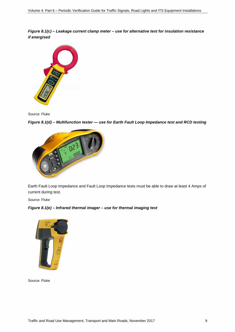
Figure 8.1(c) – Leakage current clamp meter – use for alternative test for insulation resistance if energised
Source: Fluke
Figure 8.1(d) – Multifunction tester — use for Earth Fault Loop Impedance test and RCD testing
Earth Fault Loop Impedance and Fault Loop Impedance tests must be able to draw at least 4 Amps of current during test.
Source: Fluke
Figure 8.1(e) – Infrared thermal imager – use for thermal imaging test
Source: Fluke

Volume 4: Part 6 – Periodic Verification Guide for Traffic Signals, Road Lights and ITS Equipment Installations
Traffic and Road Use Management, Transport and Main Roads, November 2017 10
8.2 Test requirements
8.2.1 Visual
A visual inspection shall be carried out prior to testing to confirm there are no immediate hazards and that the electrical installation is of suitable condition to proceed.
8.2.2 Earth continuity
The purpose of the test is to ensure that all exposed metal is maintained at earth potential, and to permit the circuit protection to operate under fault conditions.
Note that traffic signals and Rate 3 lighting do not require a Functional Earth (FE).
8.2.3 Neutral integrity
A neutral integrity test is to confirm that touch voltages are minimised. Possible causes are loose or poor neutral connections. Balanced phase to phase voltages and phase to neutral voltages which are significantly out of balance indicate that the neutral may be floating due to a poor or open circuit neutral connection; for example, A ph – 265 volts, B ph – 240 volts, C ph – 215 volts (3 phase circuit).
8.2.4 Main earth conductor resistance
An earth resistance test will confirm whether the connection of the equipment to earth is no greater than 0.5 Ω.
8.2.5 Insulation resistance
An insulation resistance test requires the supply to be disconnected. The integrity of the insulation is stressed by applying a direct current at 500 V (excluding exemptions, refer to Wiring Rules Clause 8.3.6.1).
As per AS 3019 Clause 4.7.4, leakage current testing is accepted (as an alternative to insulation resistance test in limited testing) when it is desirable to minimise effects on the installation and avoid the need to disconnect the supply. This test requires measurement of the current in the active and neutral conductors. Note the accepted limit of leakage current permitted is to be less than or equal to 10 mA.
8.2.6 Polarity
A polarity test is conducted to ensure the active and neutral wires are connected to the correct terminals.
8.2.7 Correct circuit connections
This test is to ensure that there are no short circuit between conductors, transposition of conductors that could result in the earthing system and any exposed conductive parts of the electrical installation becoming live, or interconnection of conductors between different CCTS.

Volume 4: Part 6 – Periodic Verification Guide for Traffic Signals, Road Lights and ITS Equipment Installations
Traffic and Road Use Management, Transport and Main Roads, November 2017 11
8.2.8 Earth Fault Loop Impedance
Note that conductor temperature can be assumed to be 20°C (due to low amount of current flowing) rather than 75°C (assumed operating at maximum current); therefore, the maximum values of Earth Fault Loop Impedance as shown in AS/NZS 3017 Clause 3.6.3.1 Table 3.1, or Wiring Rules Clause 8.3.9.3 Table 8.1 (based on conductor temperature being 75°C) should be reduced to 80% to give Earth Fault Loop Impedance values for conductor temperature of 20°C. If available, thermal imaging can be used to provide information on cable temperature.
Earth Fault Loop Impedance to be conducted on C.Mains, and final CCTS of:
• switchboards (SWBS)
• poles (lighting and signals)
• cabinets and controllers
• mastarms
• ITS cabinets
• ITS poles.
Refer to Table 8.2.8 for maximum values of Earth Fault Loop Impedance (Zs) at 230 Vac and 20°C.
Table 8.2.8 Maximum values of Earth Fault Loop Impedance (Zs) at 230 Vac (at 20°C)
Protective device rating
A
Circuit breakers Fuses
Type B Type C Type D
Disconnection times
0.4 s 0.4 s 5 s
Maximum Earth Fault Loop Impedance Zs Ω [The 20°C calculated value is 80% of the 75°C value]
75°C 20°C 75°C 20°C 75°C 20°C 75°C 20°C 75°C 20°C
6 9.583 7.880 5.111 4.203 3.067 2.522 11.500 9.456 15.330 12.605
10 5.750 4.728 3.067 2.522 1.840 1.513 6.390 5.254 9.200 7.565
16 3.594 2.955 1.917 1.576 1.150 0.946 3.070 2.524 5.000 4.111
20 2.875 2.364 1.533 1.261 0.920 0.756 2.090 1.719 3.590 2.952
25 2.300 1.891 1.227 1.009 0.736 0.605 1.640 1.349 2.710 2.228
32 1.797 1.478 0.958 0.788 0.575 0.473 1.280 1.053 2.190 1.801
40 1.438 1.182 0.767 0.630 0.460 0.378 0.960 0.789 1.640 1.349
50 1.150 0.946 0.613 0.504 0.368 0.303 0.720 0.592 1.280 1.053
63 0.913 0.750 0.487 0.400 0.292 0.240 0.550 0.452 0.940 0.773
80 0.719 0.591 0.383 0.315 0.230 0.189 0.380 0.312 0.680 0.559
100 0.575 0.473 0.307 0.252 0.184 0.151 0.270 0.222 0.480 0.395

Volume 4: Part 6 – Periodic Verification Guide for Traffic Signals, Road Lights and ITS Equipment Installations
Traffic and Road Use Management, Transport and Main Roads, November 2017 12
Protective device rating
A
Circuit breakers Fuses
Type B Type C Type D
Disconnection times
0.4 s 0.4 s 5 s
Maximum Earth Fault Loop Impedance Zs Ω [The 20°C calculated value is 80% of the 75°C value]
75°C 20°C 75°C 20°C 75°C 20°C 75°C 20°C 75°C 20°C
125 0.460 0.378 0.245 0.202 0.147 0.121 0.210 0.173 0.430 0.354
160 0.359 0.296 0.192 0.158 0.115 0.095 0.160 0.132 0.300 0.247
200 0.288 0.236 0.153 0.126 0.092 0.076 0.130 0.107 0.230 0.189
Where some installations may not be able to meet this standard due to the high ambient temperature, a Registered Professional Engineer Queensland (RPEQ) Electrical shall determine suitable alternative EFLI value, taking into account the specific site geometry.
Prior to any works, refer to site specific design data to confirm equipment type/rating installed.
8.2.9 Verification of Residual Current Device
A number of traffic controllers are equipped with a Residual Current Device (RCD) protected socket outlet, which is designed for ancillary electrical equipment.
Refer to AS 2578 Clause 1.4.10 and Wiring Rules Clause 2.6.3.2 Exception 5, note that an RCD shall not be installed in any of the CCTS used to drive the traffic signals.
A visual inspection is required to make sure these RCD protected socket outlets are not subject to any operation of traffic signals. A tripping time test of the integrated RCD is required, using an RCD tester in accordance with AS/NZS 3017 Clause 3.7.2.2, to confirm tripping time does not exceed 300 ms. The use of the integral test button is not acceptable.
8.2.10 Infrared thermal imaging
As per AS/NZS 3019 Clause 5.8, the integrity of switchboard connections should be tested out with a thermal imaging device. Both the ambient temperature and maximum temperature measured should be recorded and any items whose temperature is significantly above the ambient noted.
The possible faults which can be indicated through use of infrared thermal imaging include:
• high impedance connection
• overloads
• imbalanced CCTS
• faulty equipment
• damaged switches
• faulty fuses.

Volume 4: Part 6 – Periodic Verification Guide for Traffic Signals, Road Lights and ITS Equipment Installations
Traffic and Road Use Management, Transport and Main Roads, November 2017 13
8.2.11 Touch voltage testing
This is to ensure that the installation is fit for purpose in the environment in which it is installed and does not contribute to a dangerous electrical incident.

Volume 4: Part 6 – Periodic Verification Guide for Traffic Signals, Road Lights and ITS Equipment Installations
Traffic and Road Use Management, Transport and Main Roads, November 2017 14
Appendix A: Test procedure – traffic signals (energised)
This procedure details the required tests to be conducted for traffic signals when main circuit is live.
Reference drawings
Fig A Traffic Signals Sheet 1 of 1 Procedure (in order of sequence)
a) Visual inspection
i. Check for any dangerous vermin/biohazards in the switchboard.
ii. Make sure the switchboard door and cabinet are correctly earthed.
iii. Make sure the MEN link is available (if applicable).
iv. Check that all exposed conductors cannot be inadvertently accessed (IP2X).
v. Look for mechanically-damaged equipment, unsupported parts, and cables in tension.
vi. Visually check all earthing conductors are connected to the earth bar.
vii. Visually check that neutral conductors are connected to the neutral bar.
b) Earth continuity [no voltage test, but working in vicinity of live parts]
i. Isolate supply and confirm no voltage present on load side of main switch and neutral.
ii. Complete the following noting any possible risk. Disconnect the main earth and MEN from the neutral link. Disconnection point is the earth bar.
iii. Place Ohmmeter between the Earth bar of the controller and the post of each pedestal using suitable trailing lead.
iv. Record results (measure the resistance of the trailing lead also). Deduct value of trailing lead from the results to obtain test result.
v. Reconnect the main earth and the MEN.
This test can be replaced by completing Earth Fault Loop Impedance test if traffic conditions do not permit use of a trailing lead.
c) Neutral integrity [main circuit de-energised, but working in vicinity of live parts]
i. Turn off main switch.
ii. Confirm integrity of main earthing connection as per test sequence b) Earth continuity.
iii. Remove main earth and main neutral from main switchboard.
iv. Check operation of voltage indicator.
v. Test supply side of the main switch and main earth. Result should indicate approximately 230 – 240 Vac.
vi. Complete the following noting possible risk. Disconnect MEN link. Test between supply side of the main switch and neutral bar. A result of approximately 230 – 240 Vac indicates other neutral to earth connections within the installation. Remove neutral connection of any such circuit.

Volume 4: Part 6 – Periodic Verification Guide for Traffic Signals, Road Lights and ITS Equipment Installations
Traffic and Road Use Management, Transport and Main Roads, November 2017 15
vii. Isolate CCTS other than the test circuit. Reconnect main neutral to the neutral bar and close the main switch. Apply a substantial load. Test between main switch and neutral bar. Record the reading.
viii. Turn off main switch. Remove main neutral and connect main earth. Reconnect MEN link.
ix. Turn on main switch and test between main switch and neutral bar. Reading should be substantially the same as for step vii in this test sequence c) Neutral integrity i.e. within 5 volts.
d) Insulation resistance test (via leakage current testing)
Insulation resistance testing requires the supply to be disconnected; therefore, as per AS/NZS 3019 Clause 4.7.4, leakage current test is to be conducted using a leakage current clamp meter.
i. Simultaneously measure the current in the active and the neutral conductors under test.
ii. If leakage current is greater than 10 mA per cable run from the controller then the test should be considered to have failed and further testing is required to determine source.
e) Earth electrode, main earth, supply polarity (combined)
i. For earth electrode, perform visual inspection to look for evidence of corrosion, damage or poor connection.
ii. For main earthing conductor, perform visual inspection and confirm that:
• Main earthing conductor is correct size.
• Main earthing conductor is connected to the earth electrode by a suitable corrosion resistant connection.
• Main earthing conductor terminations are accessible.
• Connections are mechanically sounds and fixed to a secure system.
• Connections are protected against mechanical damage, corrosion or vibration.
• Connections do not impose any appreciable mechanical stress on components.
• Main earthing conductor is correctly connected at the switchboard (where applicable).
• Labelling of the main earth connection is correct.
iii. Identify the incoming mains cables, and visually check the active conductor is connected to the current limiting device (main fuse) and the neutral conductor is connected to the neutral bar.
iv. Disconnect the main earthing conductor at once established alternative earth exists, using
• Earth Continuity test (refer to test sequence b) Earth continuity)
v. Place Ohmmeter between (end of main earthing conductor) and (body of earthing electrode). The resistance of the main earth conductor shall be less than 0.5 Ω according to Wiring Rules Clause 8.3.5.2.
1
1 2

Volume 4: Part 6 – Periodic Verification Guide for Traffic Signals, Road Lights and ITS Equipment Installations
Traffic and Road Use Management, Transport and Main Roads, November 2017 16
vi. Test voltage between and Note this must be 230 – 240 Vac.
vii. Test voltage between and Note this must be 0 V.
viii. Test voltage between and Note this must be 230 – 240 Vac.
ix. If test voltage for steps vi. and viii. in this test sequence e) are as follows, then polarity is reversed and this needs to be corrected immediately:
• Step vii. = 230 – 240 Vac
• Step viii. = 0 Vac
x. Reconnect main earthing conductor to earth bar.
f) Correct circuit connections
i. Prove that the active, neutral and protective earthing conductors of each circuit are correctly connected so that there is no:
• short circuit between conductors
• transposition of conductors that could result in the earthing system and any exposed conductive parts of the electrical installation becoming live
• interconnection of conductors between different CCTS.
g) Earth Fault Loop Impedance
i. Connect Loop Tester at the last pedestal on each run.
ii. Measure EFLI, two measurements taken approximately 30 seconds apart.
iii. Confirm results are same (within 5%) – otherwise test again.
iv. Record the type and size of the Field Active protective device and Flasher Circuit protective device.
v. Record all test results (both):
The use of an active core with no other loads (or relatively low loads) will provide more accurate results.
Readings can be affected by external factors on the supply side. Further testing may be required if readings are high and do not meet the requirements of Wiring Rules.
h) Earth leakage — each run
i. Connect clamp meter around used actives and neutral only.
ii. Measure current differential for each run.
iii. Where leakage is noted to be greater than 10 mA, trace leakage back to faulty equipment and rectify.
iv. Record all results.
1 3
1 4
3 4
Volume 4: Part 6 – Periodic Verification Guide for Traffic Signals, Road Lights and ITS Equipment Installations
Traffic and Road Use Management, Transport and Main Roads, November 2017 17
i) Controller voltage and peak current
i. Connect clamp meter around incoming supply active and record peak current result during one cycle of the traffic signals.
ii. Test voltage between and record results. Note this must be 230 – 240 Vac.
j) Test RCD
i. Perform a visual inspection to make sure the socket outlets are not connected to any circuit used to drive traffic signals.
ii. Turn the RCD tester to RCD testing position.
iii. Select 30 mA current rating, full sine wave, and 0° current phase.
iv. Press and release ‘test’ (or ‘GO’) button, wait for the test to complete. Record the reading to the test report.
v. Record trip time and trip current, as well as any other factors of concern.
vi. Select 180° current phase, repeat step iv of this test sequence j) Test RCD.
vii. RCD that does not operate on test, or takes longer than 300 ms to interrupt the supply, should be replaced immediately.
k) Infrared thermal imaging
i. In accordance with AS/NZS 3019 Clause 5.8, equipment is to operate under normal operating loads for at least 30 minutes.
ii. Measure the temperature of the equipment components using the infrared thermal imaging equipment.
iii. Determine if any equipment is affected by excessive rise in temperature. If high temperature values are measured, rectify installation. Retest equipment components including use of infrared thermal imaging equipment.
l) Touch voltage testing
i. Confirm no potential exists between the department’s assets and also between assets of other entities and departmental assets.
3
3 4

Volume 4: Part 6 – Periodic Verification Guide for Traffic Signals, Road Lights and ITS Equipment Installations
Traffic and Road Use Management, Transport and Main Roads, November 2017 18
Appendix B: Test procedure – road lighting (de-energised where possible)
This procedure details the required tests to be conducted for road lighting where main circuit is de energised.
Reference drawings
Fig B Road Lighting (De-energised) Sheet 1 of 2
Fig C Road Lighting (De-energised) Sheet 2 of 2 Procedure (in order of test sequence)
a) Visual inspection
i. Check for any dangerous vermin/biohazards in the switchboard.
ii. Make sure the switchboard door and cabinet are correctly earthed.
iii. Make sure the MEN link is available (if applicable).
iv. Check all exposed conductors cannot be inadvertently accessed (IP2X).
v. Look for mechanically-damaged equipment, unsupported parts, and cables in tension.
vi. Visually check all earthing conductors are connected to the earth bar.
vii. Visually check that neutral conductors are connected to the neutral bar.
b) Earth continuity [no voltage test, but working in vicinity of live parts]
i. Isolate supply and confirm no voltage present on load side of main switch and neutral.
ii. Complete the following noting possible risk. Disconnect the main earth and MEN from the neutral link. Disconnection point is the earth bar.
iii. Place Ohmmeter between the Earth bar of the switchboard and the post of each road light using suitable trailing lead.
iv. If photo cell is located on a separate metal structure i.e. traffic signal post, then test Earth Continuity up to the photo cell.
v. Record results (measure the resistance of the trailing lead also). Deduct value of trailing lead from the results to obtain test result.
vi. Reconnect the main earth and the MEN.
This test can be replaced by completing Earth Fault Loop Impedance test if traffic conditions do not permit use of a trailing lead.
c) Neutral integrity [main circuit de-energised, but working in vicinity of live parts]
i. Turn off main switch.
ii. Confirm integrity of main earthing connection as per test sequence b) Earth continuity.
iii. Remove main earth and main neutral from main switchboard.
iv. Check operation of voltage indicator.
1

Volume 4: Part 6 – Periodic Verification Guide for Traffic Signals, Road Lights and ITS Equipment Installations
Traffic and Road Use Management, Transport and Main Roads, November 2017 19
v. Test supply side of the main switch and main earth. Result should indicate approximately 230 – 240 Vac. The consumer mains is still energised.
vi. Complete the following noting possible risk. Disconnect MEN link. Test between supply side of the main switch and neutral bar. A result of approximately 230 – 240 Vac indicates other neutral to earth connections within the installation. Remove neutral connection of any such circuit.
vii. Isolate CCTS other than the circuit being tested. Reconnect main neutral to the neutral bar and close the main switch. Apply a substantial load. Test between main switch and neutral bar. Record the reading.
viii. Turn off main switch. Remove main neutral and connect main earth. Reconnect MEN link.
ix. Turn on main switch and test between main switch and neutral bar. Reading should be substantially the same as for step vii. of this test sequence c) Neutral integrity; that is, within 5 volts.
d) Insulation resistance test
i. Ensure main switch at the main switchboard is turned off.
ii. Ensure that all protective devices are in circuit and that all switches are on.
iii. Connect one lead of the insulation tester to the main earthing bar (MEN link disconnected) and the other lead to the actives and neutrals connected together.
Do not test between actives and neutrals.
iv. Measure the insulation resistance of the total installation.
v. Results:
• If the insulation resistance is 1 M Ω or greater then reconnect the MEN link and return the installation to normal.
• If the insulation resistance is less than 1 M Ω then test all CCTS individually.
vi. Ensure that all CCTS and the MEN connection are reconnected when the testing is complete.
e) Earth electrode, main earth, polarity (combined)
i. For earth electrode, perform visual inspection to look for evidence of corrosion, damage or poor connection.
ii. For main earthing conductor, perform visual inspection and confirm that:
• main earthing conductor is correct size
• main earthing conductor is connected to the earth electrode by a suitable corrosion resistant connection
• main earthing conductor terminations are accessible
• connections are mechanically sounds and fixed to a secure system
• connections are protected against mechanical damage, corrosion or vibration

Volume 4: Part 6 – Periodic Verification Guide for Traffic Signals, Road Lights and ITS Equipment Installations
Traffic and Road Use Management, Transport and Main Roads, November 2017 20
• connections do not impose any appreciable mechanical stress on components
• main earthing conductor is correctly connected at the switchboard (where applicable)
• labelling of the main earth connection is correct.
iii. Identify the incoming mains cables, and visually check the active is connected to the current limiting device (main fuse) and the neutral is connected to the neutral bar.
iv. Disconnect the main earthing conductor at once established alternative earth exists, using:
• Earth Continuity test (refer to test sequence b))
v. Place Ohmmeter between (end of main earthing conductor) and (body of earthing electrode). The resistance of the main earth conductor shall be 0.5 Ω or less according to Wiring Rules Clause 8.3.5.2.
vi. Test voltage between and Note this must be 230 – 240 Vac.
vii. Test voltage between and Note this must be 0 V.
viii. Test voltage between and Note this must be 230 – 240 Vac.
ix. If test voltage for steps vii. and viii. of this test sequence e) are as follows, then polarity is reversed and this needs to be corrected immediately:
• Step vii. = 230 – 240 Vac
• Step viii = 0 Vac
x. Reconnect main earthing conductor to earth bar.
f) Correct circuit connections
i. Prove that the active, neutral and protective earthing conductors of each circuit are correctly connected so that there is no:
• short circuit between conductors
• transposition of conductors that could result in the earthing system and any exposed conductive parts of the electrical installation becoming live
• interconnection of conductors between different CCTS.
g) Earth Fault Loop Impedance (each light to be tested individually requires circuit to be energised)
i. Confirm light switch is ON and the light is energised.
ii. Connect Loop Tester at the road light on each run. Measure EFLI at load side of the
switch (if there is no isolation switch, test on the load side of the terminals).
iii. Take a reading.
iv. Record the type and amp rating of the protective device.
1
1 2
1 3
1 4
3 4
5
Volume 4: Part 6 – Periodic Verification Guide for Traffic Signals, Road Lights and ITS Equipment Installations
Traffic and Road Use Management, Transport and Main Roads, November 2017 21
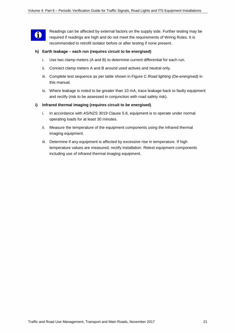
Readings can be affected by external factors on the supply side. Further testing may be required if readings are high and do not meet the requirements of Wiring Rules. It is recommended to retrofit isolator before or after testing if none present.
h) Earth leakage – each run (requires circuit to be energised)
i. Use two clamp meters (A and B) to determine current differential for each run.
ii. Connect clamp meters A and B around used actives and neutral only.
iii. Complete test sequence as per table shown in Figure C Road lighting (De-energised) in this manual.
iv. Where leakage is noted to be greater than 10 mA, trace leakage back to faulty equipment and rectify (risk to be assessed in conjunction with road safety risk).
i) Infrared thermal imaging (requires circuit to be energised)
i. In accordance with AS/NZS 3019 Clause 5.8, equipment is to operate under normal operating loads for at least 30 minutes.
ii. Measure the temperature of the equipment components using the infrared thermal imaging equipment.
iii. Determine if any equipment is affected by excessive rise in temperature. If high temperature values are measured, rectify installation. Retest equipment components including use of infrared thermal imaging equipment.

Volume 4: Part 6 – Periodic Verification Guide for Traffic Signals, Road Lights and ITS Equipment Installations
Traffic and Road Use Management, Transport and Main Roads, November 2017 22
Appendix C: Test procedure – road lighting (circuits energised)
This procedure details the required tests to be conducted for road lighting when main circuit is live.
Warning: Polarity test only indicates likelihood of reverse polarity.
Reference drawings
Fig D Road Lighting (Energised) Sheet 1 of 2
Fig E Road Lighting (Energised) Sheet 2 of 2
Refer to AS/NZS 3017 Fig 3.14 for full test sequence, where testing requiring no voltage to be applied has been substituted by obtaining current readings (test sequence d), part 2 following).
Procedure (in order of sequence)
a) Visual inspection
i. Check for any dangerous vermin/biohazards in the switchboard.
ii. Make sure the switchboard door and cabinet are correctly earthed.
iii. Make sure the MEN link is available (if applicable).
iv. Check all exposed conductors cannot be inadvertently accessed (IP2X).
v. Look for mechanically damaged equipment, unsupported parts, and cables in tension.
vi. Visually check all earthing conductors are connected to the earth bar.
vii. Visually check that neutral conductors are connected to the neutral bar.
b) Earth continuity [no voltage test, but working in vicinity of live parts](for poles can be omitted using alternative refer test sequence f))
i. Isolate supply and confirm no voltage present on load side of main switch and neutral.
ii. Complete the following noting possible risk. Disconnect the main earth and MEN from the neutral link. Disconnection point is the earth bar.
iii. Place Ohmmeter between the earth bar of the switchboard and the post of each road light using suitable trailing lead (of suitable length recommended).
iv. If photo cell is located on a separate metal structure i.e. traffic signal post, then test earth continuity up to the photo cell.
v. Record results (measure the resistance of the trailing lead also).
vi. Reconnect the main earth and the MEN.
This test can be replaced by completing Earth Fault Loop Impedance test if traffic conditions do not permit use of a trailing lead
1

Volume 4: Part 6 – Periodic Verification Guide for Traffic Signals, Road Lights and ITS Equipment Installations
Traffic and Road Use Management, Transport and Main Roads, November 2017 23
c) Insulation resistance test (via leakage current testing)
Insulation resistance testing requires the supply to be disconnected; therefore, as per AS/NZS 3019 clause 4.7.4, leakage current test is to be conducted using a leakage current clamp meter.
i. Simultaneously measure the current in the active and the neutral conductors under test.
ii. If leakage current is greater than 10 mA then further testing is required to determine source.
d) Polarity test
Test sequence part 1 – Voltage readings
The following test sequence shall be completed with the supply on.
i. Check operation of voltage indicator test unit.
ii. Confirm main switch closed.
iii. Connect one test lead to known earth.
iv. Connect other test lead to terminals (one at a time) of switch.
v. With switch ON, measure voltage. Voltage should be 230 – 240 Vac at both terminals.
vi. Using the test lead referenced in step iv. make contact with other test lead to active and
neutral terminal (one at a time).
vii. With switch ON measure voltage. Voltage should be 230 – 240 Vac at active terminal, 0
Vac at neutral terminal.
viii. Disconnect test lead from earth.
e) Correct circuit connections
i. Prove that the active, neutral and protective earthing conductors of each circuit are correctly connected so that there is no:
• short circuit between conductors
• transposition of conductors that could result in the earthing system and any exposed conductive parts of the electrical installation becoming live
• interconnection of conductors between different CCTS.
f) Earth Fault Loop Impedance (each light to be tested individually)
i. Confirm light switch is ON.
ii. Connect Loop Tester at the road light on each run. Measure EFLI at load side of the
switch.
1
2
3
4
1
5
1
3
6

Volume 4: Part 6 – Periodic Verification Guide for Traffic Signals, Road Lights and ITS Equipment Installations
Traffic and Road Use Management, Transport and Main Roads, November 2017 24
iii. Take two sets of readings, about 30 seconds apart.
iv. Confirm results are same – otherwise test again.
v. Record the type and size of the protective device.
g) Infrared thermal imaging
i. In accordance with AS/NZS 3019 Clause 5.8, equipment is to operate under normal operating loads for at least 30 minutes.
ii. Measure the temperature of the equipment components using the infrared thermal imaging equipment.
iii. Determine if any equipment is affected by excessive rise in temperature. If high temperature values are measured, rectify installation. Retest equipment components including use of infrared thermal imaging equipment.

Volume 4: Part 6 – Periodic Verification Guide for Traffic Signals, Road Lights and ITS Equipment Installations
Traffic and Road Use Management, Transport and Main Roads, November 2017 25
Appendix D: Result Sheet – traffic signals (energised)
Note: This is an example only. Use latest approved version only.

Volume 4: Part 6 – Periodic Verification Guide for Traffic Signals, Road Lights and ITS Equipment Installations
Traffic and Road Use Management, Transport and Main Roads, November 2017 26
Appendix E: Result Sheet – road lighting
Note: This is an example only. Use latest approved version only.
Volume 4: Part 6 – Periodic Verification Guide for Traffic Signals, Road Lights and ITS Equipment Installations
Traffic and Road Use Management, Transport and Main Roads, November 2017 27
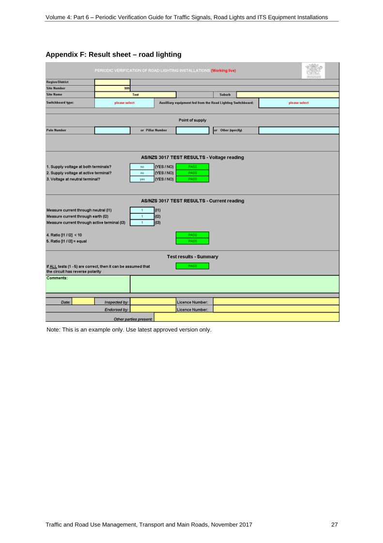
Appendix F: Result sheet – road lighting
Note: This is an example only. Use latest approved version only.

Volume 4: Part 6 – Periodic Verification Guide for Traffic Signals, Road Lights and ITS Equipment Installations
Traffic and Road Use Management, Transport and Main Roads, November 2017 28
Associated Drawings

Volume 4: Part 6 – Periodic Verification Guide for Traffic Signals, Road Lights and ITS Equipment Installations
Traffic and Road Use Management, Transport and Main Roads, November 2017 29

Volume 4: Part 6 – Periodic Verification Guide for Traffic Signals, Road Lights and ITS Equipment Installations
Traffic and Road Use Management, Transport and Main Roads, November 2017 30

Volume 4: Part 6 – Periodic Verification Guide for Traffic Signals, Road Lights and ITS Equipment Installations
Traffic and Road Use Management, Transport and Main Roads, November 2017 31

Volume 4: Part 6 – Periodic Verification Guide for Traffic Signals, Road Lights and ITS Equipment Installations
Traffic and Road Use Management, Transport and Main Roads, November 2017 32
