performing rin and rin oma measurements on the dsa8300...
TRANSCRIPT

Performing RIN and RIN OMA Measurements on the DSA8300 Sampling OscilloscopeApplication Note
Application Note
www.tektronix.com/dsa83002
A general consideration on measurements of RIN with an optical, equivalent time sampling oscilloscope is given here. Detailed information on the measurement of the RIN OMA for the purpose of 10 Gb/s Ethernet, IEEE 802.3ae and similar specifications is presented.
Table of Contents1. Definition of RIN and RINxOMA .................................3
2. Procedure, Example Calculation ...............................7
3. Oscilloscope Noise Contribution ...............................9
4. Conclusion ..................................................................9
5. Bibliography ................................................................9
www.tektronix.com/dsa8300 3
Performing RIN and RIN OMA Measurements on the DSA8300 Sampling Oscilloscope
1. Definition of RIN and RINxOMAIn the most basic definition RIN (Relative Intensity Noise) is a ratio of the laser's intensity noise to power. This is then typically expressed over the bandwidth of interest:
Where:
RIN = Relative Intensity Noise referred to optical high amplitude,
PN = Noise power in watts (no modulation)
PC = power of continuous wave (no modulation),
BW = Low-pass bandwidth of an optical-electrical receiver system, or of the measuring system in [Hz].
This measurement can be performed with a spectrum analyzer (for the value of noise power; the spectrum analyzer is AC-coupled) and a power meter (for the value of power of the laser with continuous high level).
In actual optical transmitter the behavior of the laser alone is of less interest than a measure of the noise on the modulated signal relative to optical signal amplitude of the modulated light.
Several measures of optical signal amplitude can be considered, for example AOP (average optical power) or OMA1.
1OMA, optical modulation amplitude, is the difference between the high level and the low level, each level measured in a particular part of the waveform.
2The IEEE 802.3ae uses the symbol PN resp. PM; in this paper we’ve added the subscript extension _e to emphasize the fact that this parameter is electrical, not optical.
There are some advantages to considering OMA as the measure of the optical signal’s power, and since this is used in a very common standard (802.3ae Ethernet - since 2002, and several follow-on standards) such measurement became the common way to evaluate the relative intensity noise in data communication transmitters. This measurement is then referred to as RIN OMA measurement and is performed as defined below.
Another consideration is that since the laser’s relative intensity noise is a function of the optical return loss of the system the laser is connected to, the RIN should be measured with particular reflection magnitude in mind. The reflection coefficient is in this case by convention labeled x.
RINxOMA therefore is the Relative Intensity Noise with OMA as the measure of signal power and while the laser experiences x dB of return loss from the fiber.
The IEEE 802.3ae, e.g. 10GBASE-LR gives the method in electrical domain (after a photo-diode optical detector).
Where:
RINxOMA = Relative Intensity Noise referred to optical modulation amplitude measured with x dB reflection,
PN_e = electrical noise power in watts with modulation off2,
PM_e = electrical power in watts of the modulated signal2,
BW = (Low-pass bandwidth of filter) – (high-pass bandwidth of DC blocking capacitor) [noise bandwidth of the measuring system (Hz)].
Figure 1 (see next page) contains the diagram of the measurement setup from the IEEE 802.3 clause 52.
Equation 1
Equation 2
Application Note
www.tektronix.com/dsa83004
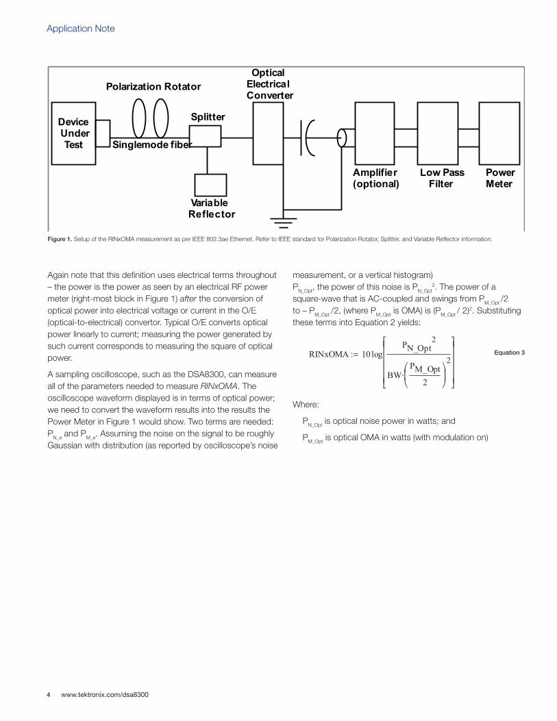
Again note that this definition uses electrical terms throughout – the power is the power as seen by an electrical RF power meter (right-most block in Figure 1) after the conversion of optical power into electrical voltage or current in the O/E (optical-to-electrical) convertor. Typical O/E converts optical power linearly to current; measuring the power generated by such current corresponds to measuring the square of optical power.
A sampling oscilloscope, such as the DSA8300, can measure all of the parameters needed to measure RINxOMA. The oscilloscope waveform displayed is in terms of optical power; we need to convert the waveform results into the results the Power Meter in Figure 1 would show. Two terms are needed: PN_e and PM_e. Assuming the noise on the signal to be roughly Gaussian with distribution (as reported by oscilloscope’s noise
measurement, or a vertical histogram) PN_Opt, the power of this noise is PN_Opt
2. The power of a square-wave that is AC-coupled and swings from PM_Opt /2 to – PM_Opt /2, (where PM_Opt is OMA) is (PM_Opt / 2)2. Substituting these terms into Equation 2 yields:
Where:
PN_Opt is optical noise power in watts; and
PM_Opt is optical OMA in watts (with modulation on)
Figure 1. Setup of the RINxOMA measurement as per IEEE 802.3ae Ethernet. Refer to IEEE standard for Polarization Rotator, Splitter, and Variable Reflector information.
Device UnderTest
Polarization Rotator
Singlemode fiber
Splitter
VariableReflector
OpticalElectricalConverter
Amplifier(optional)
Low PassFilter
PowerMeter
Figure 52–7—RINxOMA measurement setup
Equation 3

www.tektronix.com/dsa8300 5
Performing RIN and RIN OMA Measurements on the DSA8300 Sampling Oscilloscope
Figure 2 shows a setup for the RINxOMA measurement following the IEEE 802.3ae Ethernet when using a DSA8300 oscilloscope.
Refer to IEEE standard for Polarization Rotator, Splitter, and Variable Reflector information, noting that only a subset is used in the test of a multi-mode device. The loss <x> dB of reflection loss in “optical path and detector combination” must be configured for a single dominant reflection with an optical return loss specified by the standard; RIN21OMA for example is specified for 10GBASE-E.
The IEEE document also mentions that Optical return loss may be determined by the method of FOTP-107; and the length of the test cable is not critical but should be in excess of 2 m. Clock Recover is optional (depends on DUT Clock availability) and for some speeds can even be built into the optical module.
Figure 2. Setup of the RINxOMA when using an optical oscilloscope.
Application Note
www.tektronix.com/dsa83006
It is common for optical transmitters to present lower noise power in the optical low state than in optical high state. It is then pessimistic to simply use the noise power at high level as in Equation 2; accounting for that yields:
Which simplifies to:
Where:
RINxOMA1 = Relative Intensity Noise referred to optical modulation amplitude measured with x dB reflection,
PN_Opt_H_meas = Optical noise power in watts at high level, as measured (with oscilloscope’s own noise included)
PN_Opt_L_meas = Optical noise power in watts at low level, as measured (with oscilloscope’s own noise included)
PM_Opt_OMA = Optical OMA in watts with modulation on,
BW = Bandwidth of the low-pass filter in case of an optical reference receiver (ORR) mandated by optical standard,
BW:= BWORR *1.05; where BWORR is the Optical Reference Receiver bandwidth, typically BWORR := 0.75*bit_rate_frequency [Hz; Hz], so
BW:= 1.05*0.75*bit_rate_frequency3 [Hz; Hz]
Also see "Section 3: Oscilloscope Noise Contribution" for even more accurate calculation that includes accounting for the oscilloscope’s own noise, a step that is important if the oscilloscope optical plug-in noise is close in size to the noise of the optical signal.
Equation 4
3bit_rate_frequency = 1/UI [Hz; s] e.g. 10 GHz for 10 GBd, i.e. 10 Gb/s PAM2.

www.tektronix.com/dsa8300 7
Performing RIN and RIN OMA Measurements on the DSA8300 Sampling Oscilloscope
2. Procedure, Example CalculationMeasurement procedure: we recommend that the instrument should be compensated (the thermometer gauge in the bottom right of the oscilloscope screen should be green). Please follow the instruction manual if this is not the case.
2.1. Setup the optical test system as per the Figure 2. In case of an multi-mode system remove the polarization rotator. Optical return loss should match the requirement of particular standard. Lower optical return loss will give pessimistic results.
2.2. Set the optical channel that will be used for the measurement (e.g. ch1) for the correct wavelength. See Figure 3.
2.3. Set the optical ORR (optical reference receiver), i.e. set the Vert Signal Conditioning Filter for the appropriate bit-rate. For example if testing a 10 Gb/s system, the Filter should be set to an 10Gb/s ORR (optical Reference Receiver), such as 10GBASE-R4.
2.4. With the Transmitter (DUT) disconnected, measure the noise of the oscilloscope alone, PN_scope. Use RMSN5 measurement.
This is equivalent to the IEEE 802.3 clause 52.9.6.3 (a), although with a small change (the oscilloscope doesn’t need to 'zero' the result as it’s using the RMSN measurement).
Store the residual noise power, PN_scope (e.g.: around 1.8 µW in a 10Gb/s system with 80C08C sampling module in the DSA8300 oscilloscope).
Figure 3. Setting/verifying the Optical Channel’s wavelength and Filter selection.
4Note that the 10 Gb/s standard requires an ORR (opt. ref. receiver) with about 10 GHz bandwidth. Such ORR is specified for historical reasons at a ¼ optical power bandwidth at 0.75 * bit_rate_frequency , which is the -3 dB of the electrical power (after O/E) at 0.75 * bit_rate_frequency.
5Alternatively it is also fine to use the DSA8300’s histogram measurement, in which case read the StdDev readout.

Application Note
www.tektronix.com/dsa83008
2.5. With the DUT transmitting a pattern6, connect the transmitter DUT; enable the DSA8300 pattern trigger, lock the pattern on the screen. Find a sequence of several consecutive high level UIs.
Setup measurements as documented by Figure 4:
2.6. Find a flat area in the sequence of several consecutive high UIs; use Setup Meas to setup a measurement on RMSNoise. Setup two such measurements, measurement 1 and measurement 2.
2.7. Setup Meas Region to gate the measurement 1 the logic high level and Setup Meas Region to gate the measurement 2 the logic zero level.
2.8. Setup measurement 3 by selecting the OMA measurement and gating with left gate just slightly before the fall of the last pulse before the flat logic zero area.
OMA should be measured on a long sequence of low and high bits.
2.9. Manipulate the optical polarization rotator to maximize the signal noise.
2.10. Calculate RINxOMA from Equation 4, E.g.:
Figure 4. Measuring OMA and noise on a sequence of several zeroes and several ones.
6We recommend a PRBS9 pattern.

www.tektronix.com/dsa8300 9
Performing RIN and RIN OMA Measurements on the DSA8300 Sampling Oscilloscope
3. Oscilloscope Noise ContributionFinal improvement discussed is the removal of the oscilloscope’s own noise (measured as PN_scope in 2.4):
The Equation 5 is approximately valid if: PN_Opt_L > PN_scope and PN_Opt_H > PN_scope, i.e. the DUT’s own noise level is larger than the oscilloscope’s own noise level. If this is not the case the equation theoretically still holds but practically becomes problematic – e.g. unstable – the more the inequalities above are violated, the more unstable the result will be. In the future a more precise measure for validity of the instrument noise de-embedding (Equation 5) might be developed.
4. ConclusionA brief discussion of measurement of RIN (Equation 1) and RINxOMA (Equation 5; or less accurate but simpler Equation 4) is given. Also given in "Section 2: Procedure" is an example procedure to measurement of RINxOMA with a DSA8300 Sampling oscilloscope.
5. Bibliography[1] IEEE Std 802.3™; in particular the work in the IEEE 802.3ae™, section 52.9.6.*; and equation (52–1);
[2]"RIN Comment on FC-PI", http://www.t11.org/ftp/t11/pub/fc/pi/01-456v0.pdf
Equation 5
For Further InformationTektronix maintains a comprehensive, constantly expanding collection of application notes, technical briefs and other resources to help engineers working on the cutting edge of technology. Please visit www.tektronix.com
Contact Tektronix:ASEAN / Australia (65) 6356 3900
Austria* 00800 2255 4835Balkans, Israel, South Africa and other ISE Countries +41 52 675 3777
Belgium* 00800 2255 4835Brazil +55 (11) 3759 7627Canada 1 (800) 833-9200
Central East Europe and the Baltics +41 52 675 3777Central Europe & Greece +41 52 675 3777
Denmark +45 80 88 1401Finland +41 52 675 3777
France* 00800 2255 4835Germany* 00800 2255 4835
Hong Kong 400-820-5835Ireland* 00800 2255 4835
India +91-80-30792600Italy* 00800 2255 4835
Japan 0120-441-046Luxembourg +41 52 675 3777
Macau 400-820-5835Mongolia 400-820-5835
Mexico, Central/South America & Caribbean 52 (55) 56 04 50 90Middle East, Asia and North Africa +41 52 675 3777
The Netherlands* 00800 2255 4835Norway 800 16098
People’s Republic of China 400-820-5835Poland +41 52 675 3777
Portugal 80 08 12370Puerto Rico 1 (800) 833-9200
Republic of Korea +822-6917-5000Russia +7 495 664 75 64
Singapore +65 6356-3900South Africa +27 11 206 8360
Spain* 00800 2255 4835Sweden* 00800 2255 4835
Switzerland* 00800 2255 4835Taiwan 886-2-2656-6688
United Kingdom* 00800 2255 4835USA 1 (800) 833-9200
* If the European phone number above is not accessible, please call +41 52 675 3777
Contact List Updated June 2013
Copyright © 2014, Tektronix. All rights reserved. Tektronix products are covered by U.S. and foreign patents, issued and pending. Information in this publication supersedes that in all previously published material. Specification and price change privileges reserved. TEKTRONIX and TEK are registered trademarks of Tektronix, Inc. All other trade names referenced are the service marks, trademarks or registered trademarks of their respective companies.
07/14 EA/WWW 85W-30657-0