performanceofnongrouted thin bonded …publications.iowa.gov/22112/1/iadot_hr_291_nongrouted...i...
TRANSCRIPT
I
' ~·
' !
, I
l~ '),rtl
I'
.,
PERFORMANCEOFNONGROUTED THIN BONDED PCC OVERLAYS
TE 220.3 .H37 1986
17-T68HR 9 :P417 . 1986
Construction Report
Iowa Highway Research Board Project HR-291
•
August 1986

~-------------~- ------------------
CONSTRUCTION REPORT IOWA HIGHWAY RESEARCH BOARD
PROJECT HR-291
PERFORMANCE OF NONGROUTED . THIN BONDED P.C.C. OVERLAYS
AUGUST, 1986
BY
MARK K. KALER CONSTRUCTION ENGINEER
IOWA CONCRETE PAVING ASSOCIATION (515) 278-0606
AND
JOHN LANE P.C. CONCRETE ENGINEER
IOWA DEPARTMENT OF TRANSPORTATION (515) 239-1226
AND
MILTON L. JOHNSON, P~E. COUNTY ENGINEER
WAPELLO "COUNTY (515) 684-5425

I NTRODU CTI ON
OBJECTIVE
EVALUATION
PRELIMINARY INVESTIGATION
TABLE OF CONTENTS
CONSTRUCTION CRITERIA & PROCEDURES
PERFORMANCE
CONCLUSION
REFERENCES Test Method No. Iowa.406-B
TABLES Shear Strength Results-June 18, 1985 Shear Strength Results-July 30, 1985 Shear Strength Results-June 3, 1986 Shear Strength Results-May 5, 1986 Road Rater Results-May 20, 1986
Page.
1
2
2.
2
3
3
5
6-7
8 9
10 11 12
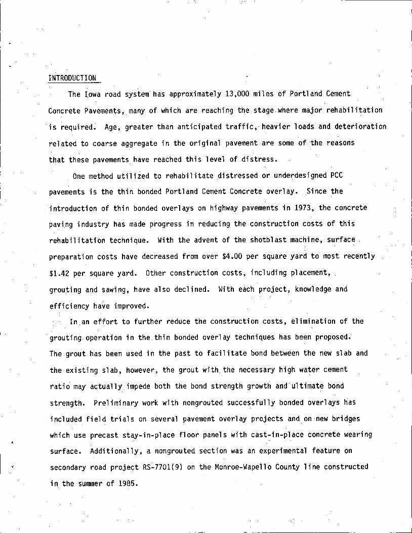
INTRODUCTION
The I.owa road system· has approximately 13,000 miles of Portland Cement
Concrete Pavements, many of which are reaching the stage where major rehabilitation
is required. Age, greater than anticipated traffic,· heavier loads and deterioration
related to coarse aggregate in the original pavement are some of the reasons
that these pavements have reached this level of distress.
One method utilized to rehabilitate distressed or underdesigned PCC
pavements is the thin bonded Portland Cement Concrete overlay. _Since the
introduction of thin bonded overlays on highway pavements in 1973, the concrete
paving industry has made progress in reducing the construction costs of this
rehabilitation technique. With the advent of the shotblast machine, surface.
preparation costs have decreased from over $4.00 per square yard to most recently
$1.42 per square yard. Other construction costs, including placement,
grou:ting and sawing, have also declined. With each project, knowledge and
efficiency have improved.
In an effort to further reduce the construction costs, elimination of the
·grouting. operation in the.thin bonded overlay techniques has been proposed.
The grout has been used in the past to facilitate bond between the new slab and
the existing slab, however, the grout with. the necessary high water cement
ratio· may actually impede both the bond strength growth and ultimate bond
strength. Preliminary work with nongrouted successfully bonded overlays has
included field trials on several pavement overlay projects and_on new bridges
which use precast stay-in-place floor panels with cast-in-place concrete wearing
surface. Additionally, a nongrouted section wa~ an experimental feature on
secondary road project RS:..7701(9) on the Monroe-Wapello County line constructed
in the summer of 1985.
·,,
- 2 -
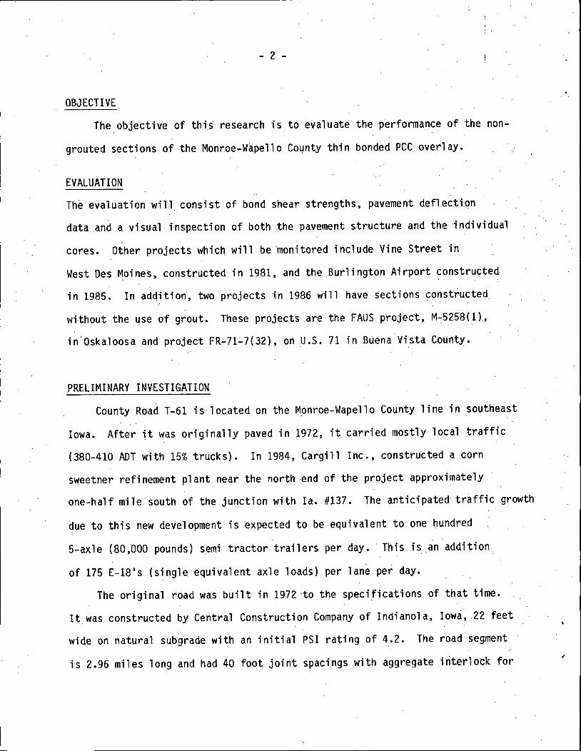
OBJECTIVE
The objective of thi.s research is to evaluate the performance of the non
grouted sections of the Monroe-Wapello County thin bonqed PCC overlay.
EVALUATION
The evaluation will consist of bond shear strengths, pavement deflection
data and a visual inspection of both the pavement structur~ and the individual
cores. Other projects which will be ~onitored include Vine Street in
West Des Moines, constructed in 1981, and the Burlington Airport ~onstructed
in 1985. In addition, two projects in 1986 will have sections constructed
wi-thout the use of grout. These projects are the FAUS project, M-:5258( 1),
in.Oskaloosa .and project FR-71.:..7(32), on U.S. 71 in BuenaVista County.
PRELIMINARY INVESTIGATION
County Road T-61 is·located on the Monroe-Wapello County line in southeast
Iowa. After it was originally paved in 1972, it carried mostly local traffic
(380-410 ADT with 15% trucks). In 1984, Cargill Inc., constructed a corn
sweetner refinement plant near the north end of the project approximately
one-half mile south of the junction with Ia. #137. The anticipated traffic growth
due to this new development is expected to be equivalent to one hundred
5-axle (80,000 pounds) semi tractor trailers per day.· This is.an addition
of 175 E-18 1 s (single equivalent axle loads) per lane per day.
The original toad was built in 1972 ·to the specifications of that time.
It was constructed by Central Construction Company of Indianola, Iowa, .22 feet
wide on natural subgrade with an initial PSI rating of 4.2. The ioad segment
is 2.96 miles long and had 40 foot joint spacings with aggregate interlock for
- 3 -
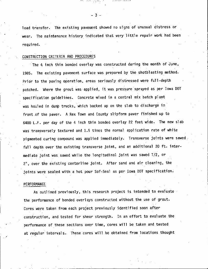
load transfer. The existing pavement showed no signs of unusual distress or
wear. The maintenance history indicated that very little repair work had been
required.
CONSTRUCTION CRITERIA AND PROCEDURES
·The 4 inch thin bonded overlay was constructed during the month of June,
1985. The existing pavement surface was prepared by the shotblasting method.
Prior· to the paving operation, areas seriously disfressed were full-depth
patched. Where the grout was·applied, it was pressure sprayed as per Iowa DOT
specification guideli~es. Concrete mixed in a central mix batch plant
was hauled in dump trucks, which backed up on the slab to discharge in
front .of the paver. A Rex Town and County slipform paver finished up to
6400 L.F. per day of the 4 inch thin bonded overlay 22 feet wide. The new slab
was transversely textured and 1.5 times the normal application rate of white
pigmented curing compound was applied immediately. Transverse joints were sawed.
full depth. over the existing transverse joint, and an additi anal 20 ft. inter
mediate joint was.sawed while the longitudinal joint was sawed T/2, or
2"i over t~e ~xisting centerline joint. After sand and air cleaning, the
joints ·were sealed with a hot pour Sof-Seal as per Iowa DOT specification~
PERFORMANCE
As outlined previously, this research project is intended to eval.uate
the performance of bonded overlays constructed without the use of grout.
Cores were taken from each project previously identified soon after
construction, and tested for shear strength. In an effort to evaluate the
performance of these sections over time, cores will be taken and tested
at regular intervals. These cores will be obtained from locations thought

- 4 -
to be most critical in terms of bond, such as at the header, wheel paths
and near the ceriterline joint. Also cores will be taken at less·critical
areas in order to distinguish variations between different sections.-· In
addition, .several cores will be stored in the DOT Materials laboratorY
out of the natural ·environment, and will be tested periodically in an effort
to determine the effects of weather and temperature on bond performance.
During the paving sequence of the Monroe-Wapello project, two 250-foot
sections were constructed without the grout application. These test sections
are 1 ocated between Stations 419+75 - 422+25 arid Stations 443+25 .- 445+25.
Within twenty four hours of paving, three. cores were taken in the first test
section and tested· for bond shear strength. The cores were .tested in accordance
with !DOT I.M. 4068 •.. Figure A. The results ranged between 278 psi and
· 596 psi with an ave~~ge of 408 psi. Fdr design purposes a bond strerigth
of 200 psi is specified. However, the higher the bond strengths achieved,
the higher the fatigue and durability inherent to the rehabilitated pavement •. ·
Since the first test section yielded positive results, a second test section
was built the next day coming directly off of the header. This section was
selected as. a greater. challenge in terms of achieving bond. Cores were taken
at the midpanel, wheel path, and near the longitudional joint in both test
sections as well as in the adjacent control sections. These cores were tested
at 14 days. The grouted sections had an_ average bond strength of 388 psi
while the non-grouted sections had an average bond strength of 640 psi.
The grouted sections ranged from 199 psi.to 577 psi while the non.:.grouted
sections ranged from 378 psi to 947 psi •. See Table 1-1 and Table 1-2 for
complete results. It appears that there _was a siqnificant bond strength
advantage when constructing the bonded overlay without the use of grout.
- 5 -
In June, 1986 the second stage of this research. evaluation began. The
same t~st sections were cored and tested for sh~ar strength. For the nongrouted
sections the results of the six cores ranged between 398 psi and 955 psi with
an average sheer strength of 638 psi. The grouted control section test results
ranged from 282 p~i to 1,527 psi with an average shear strength of 685. (Table 1-3)
There was a significant increase in bond strength over. the past year for the
grouted sections while the nongrouted remained rather constant. The reason for
the appearance of a substantial bond strength gain in the grouted sections
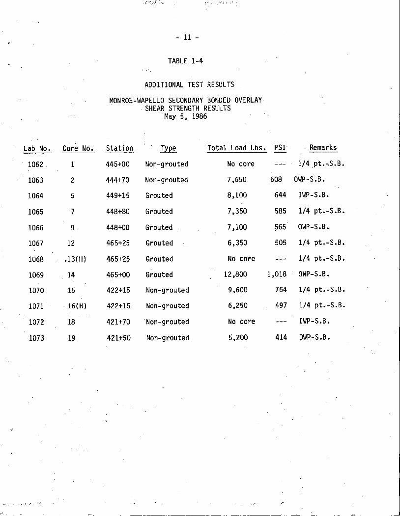
is not fullY understood. Additional cores were taken and tested and results
are shown in Table 1-4, however, the locations of the cores were not according
to the coring scheme previously established. Road rater data taken shows no
indication of any abnormal results. (Table 1-5) The data shows that significant
bond strengths were obtai ned without the use of grout, and that this procedure
could be justified in future bonded overlays.
CONCLUSION
Even though there appears to be some advantage provided by the non
grouted method, it is too early to conclusively make any statements with
regards to the overall performance of nongrouted thin bonded overlays.

-
....
.,....
Page 1 of 2
- 6 -FIGURE A
Test Method No. Iowa 406-B September 1984
IOWA DEPARTMENT OF TRANSPORTATION HIGHWAY DIVISION
Office of Materials
METHOD OF TEST FOR DETERMINING THE SHEARING STRENGTH OF BONDED CONCRETE
This method covers the procedure used in determining the shearing strength at the bonded interface between new and old concrete. The test is normally conducted on cores drilled from completed structures or pavements.
Procedure
A. Apparatus
1. Testing J1g to accommodate a 4" diameter specimen. The jig is designed to provide a direct shearing force at the bonded interface.
2. Hydraulic testing machine capable of applying a smooth and uniform tensile load. The accuracy of the reading shall be with ± 1.0% of the indicated load.
B. Test Specimens
1. Four-inch-diameter cores are the normal test specimen. Unless otherwise specified the cores are tested in an "as received" condition.
c. Test Procedure
l. Placing the specimen
(a) Place the specimen in the testing jig in such a manner that the bonded interface is placed in the space between the main halves of the jig.
(b) In the event that the interface is irregular and cannot entirely be placed within the specified space, the interface will be placed as close as practical and a special notation made.
(c) Carefully align the testing jig in the testing machine with the central axis of the jig in the center of the testing machine.
2. Rate of Loading
(a) Apply the tensile load continuously and without shock. Apply the load at a constant rate within the range of 400 to 500 psi per minute.
(b) Continue the loading until the specimen fails, and record the maximum load carried by the specimen during the test.
D. Calculations
1. Calculate the shear oond strength of the specimen by dividing the maximum load carried by the specimen during the test by the cross-sectional area and express the result to the nearest psi.

Test Method No. Iowa 406
• t , . ·~ -
- 7 -
Figure 1. Testing jig
Figure 2. Hydraulic Testing Machine , Testing jig and specimen
Page 2 of 2
-
-

Lab No.
ACE5-1083
ACE5-1084
ACE5-1085 .
- 8 -
TABLE 1-1
MONROE-WAPELLO SECONDARY BONDED OVERLAY SHEAR STRENGTH RESULTS
Core No.
1
2
3
June 28, 1985
Shear Strength, PSI
350
596
278
Avg. = 408
Location
South end of nongrouted section 25 ft. from grouted area. 18 Inches from centerline.
Middle of nongrouted section. 18 Inches from west edge.
25 Ft. from north edge of test section. 18 Inches from centerlinel. Nongrouted.

ACES-
1267 1268 1269 1270 1271 1272 1273 1274 1275 1276 1277 1278 1279 1280
- 9 -
TABLE 1-2
MONROE-WAPELLO SECONDARY BONDED OVERLAY SHEAR STRENGTH RESULTS
July 30, 1985
TOTAL· SHEAR CORE NO. · LOAD, LBS STR., PSI. . STATION
.· 1 5500 438 418+80 2 2500 199 419+50 3 10900 867 420+30 4 5600 446 420+00 5 7400 589 421+90 6 2650 211 422+80 7 4400 350 423+80 8 4400 350 441+40 9 7000 557 442+50
10 8350 664 443+40 11 11900 947 444+50 12 4750 378 445+00 13 7250 577 446+00 14 5250 418 446+90
LOCATION REMARKS
51 Rt. CL Grouted 21 Rt. CL Grouted 91 Rt. CL Non grouted 41 Lt. CL Nongrouted 61 Rt. CL Non grouted 71 Lt. CL Grouted 41 Rt. CL Grouted 6 1 Rt. CL Grouted 31Lt. CL Grouted 8 1 Rt. CL Nongrouted 91 Rt. CL Non grouted 21 Rt. CL Nongrouted 31 Lt. CL Grouted s•Rt. CL Grouted

~----------.,-------------------·-----
14 - Day 19a5 ·
STATION
41a+33 419+ao 420+47
- 10 _ ..
TABLE 1-3 .
'MONROE-WAPELLO SECONDARY BONDED OVERLAY SHEAR STRENGTH RESULTS
June 3, 19a6
SHEAR TYPE LOCATION STR. PSI
Grouted 5• Rt. . 43a Grouted .· 21 Lt. 199 Non grouted 91 Rt. .a67
421+00 . Nongrouted 41 Lt. 446 421+90 .· Non grouted 61 Rt. 5a9 422+70 Grouted 71 Lt • 211 423+74 Grouted . 41 Rt. 350 441+45 Grouted 61 Rt. 350 442+37 Grouted 31 Lt. 557 443+40 Nongrouted a• Rt. 664 444+50 Nongrouted 91 Lt. 947. 445+03 Nongrouted '21 Rt. 37a 446+00 Grouted . 31 Lt. 577 446+90 Grouted 5. Rt. 41a
19a5 Ave. · Grouted 3aa psi Non grouted .,. 64a psi
ONE YEAR RESULTS - 19a6 SHEAR
STATION TYPE LOCATION STR. PSI
41a+33 Grouted 5• Rt. +: 306 419+ao Grouted 41 Lt. 2a2 420+47 Non grouted a• Rt. 955 421+00 Non grouted 5·· Lt. 41a 422+15 Non grouted 5. Lt. 497 422+70 Grouted a· Lt. 664 423+74 Grouted 41. Rt. + 545·. 441+45 Grouted 71 Rt • 1527 442+37 Grouted . 41 Lt. 732 443+40 Non grouted a· Rt. + 39a 444+70 Non grouted a· Lt. 60a 445+03' Non grouted 31 Rt. 955 446+00 Grouted · 31 Lt. + 74a 446+90 Grouted 61 Rt. 676
19a6 Ave. ~ 6a5 psi Grouted Nongrouted 63a psi
AVE. SH. STR. PSI
31a
634
367
663
. ... 497
AVE. SH. STR. PSI
294'
623
a67
6~3
712.
'
i . - 11 -
Lab No. Core No.
1062. 1
1063 2
1064 5
1065 ·7
1066 9.
1067 12
1068 .13(H)
1069 14
1070 15
1071 · 16 (H)
1072 18
1073 19
"' • ~ •' •,\ '.\r ,• • ...... :;:
TABLE 1-4 ,·,,·.
ADDITIONAL TEST RESULTS
MONROE-WAPELLO SECONDARY BONDED OVERLAY . SHEAR STRENGTH RESULTS
May 5, 1986
Station Type Total Load Lbs.
445+00 Non-grouted No core
444+70 Non-grouted 7,650
449+15 Grouted 8,100
448+80 Grouted 7,350
448+00 Grouted 7,100
465+25 Grouted 6,350
465+25 Grouted No core
465+00 Grouted 12,800
422+15 .Non-grouted 9,600
422+15 Non.:.grouted 6,250
421+70 'Non-grouted No core
.421+50 Non-grouted 5,200
- ... _ .... -
PSI· Remarks
1/4.pt • ...,S.B.
608 OWP-S.B.
644 IWP-S.B.
585 1/4 pt.-S.B.
?65 OWP-S.B.
505 1/4 pt.-S.B.
1/4 pt.-S.B.
1,018 OWP-S.B.
764 1/4 pt.-S.B.
497 1/4 pt.-S~B.
IwP:..s.B.
414 OWP-S.B.

Sta.
390 392 394 396 398 400 402 404 406 408 410 412 414 416 418 420 422 424 426 428 430 432 434 436 438 440 442 444 446 448
AVE. STD. D SR = K =
- 12 -
TABLE 1-5
MAY 20, 1986 ROAD RATER HR-291 WAPELLO CO.
Sen 1 Sen: 2
0.72 0.70 ·0.93 0.-88 1.10. 1.00 0.76 o.n o.n 0.68 0.80. 0.75 0.74 o.7o 0.99 0.95 i.10 1.00 0.88 0.81 0.76 0.76 1.30 1.20 0.56 0.55 1.20 1.10 0.79 0.77 0.77 0.76 o~8o 0.76 0~90 0.88 0.66 o.64 0.77 0.74 0.58 0.57 0.95 0 •. 93
. 0.67 0~66 0.77 0 • .74 0.66 o:63 0.93 0.:90 0.92 0 •. 90 0.93 0.88 0.65 0.63 0.74 0.72
0.835 0·797 0.;177 0".154
6.1 150
/
SR K.
6.9 145 5.6 150 4.9 165 .. 6.6 165 7.0 155 6.4 165 6.8 160 5.4 . 130 4.9 165 5.9 175 6.6 110 4.3 140 8.5 150 4.6 150 6.4 140 6.6 120 6.4 155 5.9 120 7.4 . 155 6.6 155 8.3 150 5.6 . 110 7.3 135 6.6 155 7.3 170 5.6 130 5. 7 . 115 5.6 145 7-.5 155 6.8 145
'·'