performance testing of an inline electrocoalescer device ... · pdf fileperformance testing of...
TRANSCRIPT

56 Oil and Gas Facilities • October 2015PB Oil and Gas Facilities • October 2015 October 2015 • Oil and Gas Facilities 1
Performance Testing of an Inline Electrocoalescer Device With
Medium and Heavy CrudesE.J. Grave and M.D. Olson, ExxonMobil Upstream Research Company; and
A.E. Menchaca, R.W. Westra, and M.R. Akdim, FMC Technologies
IntroductionDehydration plays a fundamental role in the production and pro-cessing of crude oil. The removal of water from heavy crude is a challenge for many oil-processing facilities, even when only top-side applications are considered (Moraes et al. 2013). It can also pose a big challenge for processing medium crudes, and in general for any highly emulsified hydrocarbon liquids, such as those ob-tained from high-pressure applications and enhanced-oil-recovery (EOR) processes.
Besides using mechanical means to separate water from oil, other common methods of enhanced dehydration include heating, use of chemical demulsifiers, and electrostatic treatment (Silset 2008). Other possible techniques are pH adjustment, filtration, and membrane separation (Eow et al. 2001). Heat treatment can effec-tively destabilize water-in-oil (WIO) emulsions; however, it is also energy intensive and typically results in a larger system footprint. Capital and operational expenditure can be considerable in conven-tional applications (Pruneda et al. 2005), and the use of heat treat-ment is either economically unattractive or impractical in subsea, Arctic, remote, or marginal field applications. Further, the solu-bility of water in oil increases with temperature. As the oil cools during transportation, free water drops out in the pipeline, which could cause flow-assurance issues. Besides this, heat treatment causes volatile hydrocarbons to flash out of the liquid phase, which can result in appreciable volume shrinkage and API-gravity reduc-tion in the heated crude oil (Manning and Thompson 1995). This means that there is a practical and economical limit in the amount of water that can be removed from crude oil through the use of heat treatment alone. For this reason, a combination of heat treatment and demulsifiers is by far the most-common method of enhanced dehydration because many crude-oil emulsions become unstable when treated with the right type and concentration of demulsifier (Arnold and Stewart 1998; Caird 2008; Kelland 2009) at high tem-perature. While chemical treatment requires a relatively lower cap-ital investment and less energy than heat treatment, it can bear a considerable operating cost, and ensuring an uninterrupted supply of chemicals to the production site can be challenging. While the supply of chemicals to any production facility can be expensive and sensitive to changes in weather conditions, market availability, or political factors, the supply of chemicals to subsea, Arctic, remote, or marginal field applications is a far greater logistical and eco-nomical challenge.
Electrostatic treatment can be effective at breaking WIO emul-sions. It is also one of the most energy-efficient methods used for destabilization of WIO emulsions (Eow et al. 2001), and is consid-ered an enabling technology for the subsea separation of produced water from heavy oil in deepwater developments (Euphemio et al. 2007). When it is used in combination with chemical and/or heat treatment, it can improve the economics of the production facility by reducing the overall energy consumption, by reducing the use of chemical demulsifier, or both. The electrical field produced by an electrostatic coalescer affects the morphology of WIO emulsions because of the polarization of dispersed water droplets in the oil
Copyright © 2015 Society of Petroleum Engineers
This paper (SPE 174090) was revised for publication from paper OTC 25373, first presented at the Offshore Technology Conference, Houston, 5–8 May 2014. Original manuscript received for review 22 July 2014. Revised manuscript received for review 13 November 2014. Paper peer approved 22 January 2015.
SummaryExxonMobil Upstream Research Company (EMURC) recently completed a subsea technology development and qualification program that included performance testing of an inline electroco-alescer device supplied by FMC Technologies (FMC). This paper will summarize the results from these performance tests.
Although heavy oil has been processed onshore successfully for many decades, processing heavy oil in deepwater, subsea, or Arctic fields is extremely challenging. One key challenge is oil/water separation, in which physical separation is constrained by the high viscosity of the crude and the narrow density difference be-tween oil and water. Installing conventional electrostatic coalescers or dehydrators is often not economical or is impractical at remote locations. As part of ExxonMobil’s subsea program, several dif-ferent separation technologies have been investigated and tested that could enable development of these fields. One example of such a technology is an inline electrocoalescer device.
An inline electrocoalescer device enhances the coalescence of water droplets dispersed in emulsified oils. This technology has the potential to improve the performance of the downstream oil/water separator considerably. By applying an electrical field to an oil/water mixture, the dispersed water droplets become polarized and reorient themselves in the electrical field. As these water drop-lets approach one another, attractive forces between the individual water droplets lead to coalescence. Larger water droplets that can be separated faster and more easily in the downstream separation equipment are formed. Such a device can be used to increase the throughput, performance, and reliability of existing oil-processing systems, while reducing the energy consumption and/or use of chemical demulsifiers. In new processing systems, either subsea or topside, deployment of such a device has the potential to sig-nificantly reduce the size and weight of the downstream separation equipment, thereby lowering the overall capital expenditure.
The results presented in this paper are from performance tests that have been carried out on an inline electrocoalescer device at FMC’s testing facilities in the Netherlands, with EMURC’s involve-ment. Extensive testing was executed with both medium and heavy crude oils. The operating temperatures were varied in a range rep-resentative for subsea processing applications, where heating of the process fluids is difficult. Thus, the performance of the inline elec-trocoalescer device was evaluated over a range of oil viscosities. Water-in-oil concentration, flow velocity, upstream shear, and elec-trical-field strength were also varied to investigate their effects on the performance of the inline electrocoalescer device. The results demonstrate that the unit is able to deliver high preconditioning per-formance to medium- and heavy-crude-oil emulsions, provided that the appropriate process conditions and electrical settings are used.
October 2015 • Oil and Gas Facilities 572 Oil and Gas Facilities • October 2015 October 2015 • Oil and Gas Facilities 3
of oil viscosities. The performance trends are presented as a func-tion of flow velocity, upstream shear, oil viscosity, and electrical-field strength.
Materials and MethodsTested Equipment. The inline electrocoalescer device that was tested is a compact, pipe-based electrocoalescer technology that uses an electrical field to polarize and rapidly coalesce dispersed water droplets in a continuous oil stream, effectively shifting the droplet-size distribution. This is reflected in a substantial increase in the size of the water droplets in the emulsion leaving the device and, consequently, a substantial reduction in the total amount of water droplets per unit volume. As a result, the oil quality (i.e., de-gree of oil dehydration) leaving the separator downstream of such a device is improved and/or the residence time required to achieve that quality is reduced.
The compact nature of such a design may further reduce the weight by a factor of two to four, as compared with commer-cially available compact electrostatic coalescers. This will enable applications in operating environments with space and weight constraints, as well as in deepwater subsea processing systems, al-lowing hydrate-free export of crude oil through long-distance pipe-lines to a host facility.
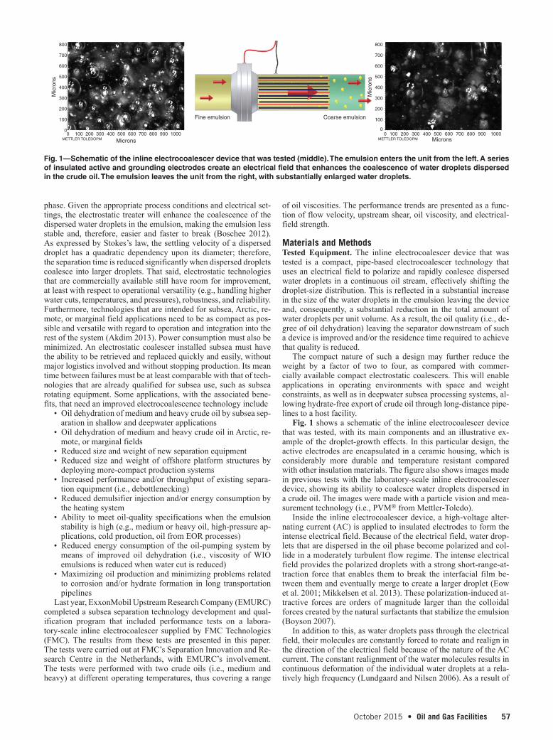
Fig. 1 shows a schematic of the inline electrocoalescer device that was tested, with its main components and an illustrative ex-ample of the droplet-growth effects. In this particular design, the active electrodes are encapsulated in a ceramic housing, which is considerably more durable and temperature resistant compared with other insulation materials. The figure also shows images made in previous tests with the laboratory-scale inline electrocoalescer device, showing its ability to coalesce water droplets dispersed in a crude oil. The images were made with a particle vision and mea-surement technology (i.e., PVM® from Mettler-Toledo).
Inside the inline electrocoalescer device, a high-voltage alter-nating current (AC) is applied to insulated electrodes to form the intense electrical field. Because of the electrical field, water drop-lets that are dispersed in the oil phase become polarized and col-lide in a moderately turbulent flow regime. The intense electrical field provides the polarized droplets with a strong short-range-at-traction force that enables them to break the interfacial film be-tween them and eventually merge to create a larger droplet (Eow et al. 2001; Mikkelsen et al. 2013). These polarization-induced at-tractive forces are orders of magnitude larger than the colloidal forces created by the natural surfactants that stabilize the emulsion (Boyson 2007).
In addition to this, as water droplets pass through the electrical field, their molecules are constantly forced to rotate and realign in the direction of the electrical field because of the nature of the AC current. The constant realignment of the water molecules results in continuous deformation of the individual water droplets at a rela-tively high frequency (Lundgaard and Nilsen 2006). As a result of
phase. Given the appropriate process conditions and electrical set-tings, the electrostatic treater will enhance the coalescence of the dispersed water droplets in the emulsion, making the emulsion less stable and, therefore, easier and faster to break (Boschee 2012). As expressed by Stokes’s law, the settling velocity of a dispersed droplet has a quadratic dependency upon its diameter; therefore, the separation time is reduced significantly when dispersed droplets coalesce into larger droplets. That said, electrostatic technologies that are commercially available still have room for improvement, at least with respect to operational versatility (e.g., handling higher water cuts, temperatures, and pressures), robustness, and reliability. Furthermore, technologies that are intended for subsea, Arctic, re-mote, or marginal field applications need to be as compact as pos-sible and versatile with regard to operation and integration into the rest of the system (Akdim 2013). Power consumption must also be minimized. An electrostatic coalescer installed subsea must have the ability to be retrieved and replaced quickly and easily, without major logistics involved and without stopping production. Its mean time between failures must be at least comparable with that of tech-nologies that are already qualified for subsea use, such as subsea rotating equipment. Some applications, with the associated bene-fits, that need an improved electrocoalescence technology include
• Oil dehydration of medium and heavy crude oil by subsea sep-aration in shallow and deepwater applications
• Oil dehydration of medium and heavy crude oil in Arctic, re-mote, or marginal fields
• Reduced size and weight of new separation equipment• Reduced size and weight of offshore platform structures by
deploying more-compact production systems• Increased performance and/or throughput of existing separa-
tion equipment (i.e., debottlenecking)• Reduced demulsifier injection and/or energy consumption by
the heating system• Ability to meet oil-quality specifications when the emulsion
stability is high (e.g., medium or heavy oil, high-pressure ap-plications, cold production, oil from EOR processes)
• Reduced energy consumption of the oil-pumping system by means of improved oil dehydration (i.e., viscosity of WIO emulsions is reduced when water cut is reduced)
• Maximizing oil production and minimizing problems related to corrosion and/or hydrate formation in long transportation pipelines
Last year, ExxonMobil Upstream Research Company (EMURC) completed a subsea separation technology development and qual-ification program that included performance tests on a labora-tory-scale inline electrocoalescer supplied by FMC Technologies (FMC). The results from these tests are presented in this paper. The tests were carried out at FMC’s Separation Innovation and Re-search Centre in the Netherlands, with EMURC’s involvement. The tests were performed with two crude oils (i.e., medium and heavy) at different operating temperatures, thus covering a range
800
700
600
500
400
300
200
100
00 100
METTLER TOLEDOPM200 300 400 500 600 700 800 900 1000
Mic
rons
Microns
Fine emulsion Coarse emulsion
800
700
600
500
400
300
200
100
00 100
METTLER TOLEDOPM200 300 400 500 600 700 800 900 1000
Mic
rons
Microns
Fig. 1—Schematic of the inline electrocoalescer device that was tested (middle). The emulsion enters the unit from the left. A series of insulated active and grounding electrodes create an electrical field that enhances the coalescence of water droplets dispersed in the crude oil. The emulsion leaves the unit from the right, with substantially enlarged water droplets.

58 Oil and Gas Facilities • October 20152 Oil and Gas Facilities • October 2015 October 2015 • Oil and Gas Facilities 3
that vibration, the mobility of water droplets dispersed in the oil phase is enhanced, which increases the probability that these water droplets will collide as they pass through the unit. Furthermore, during the collision of any two droplets, these high-frequency vi-brations increase the magnitude of the dynamic forces acting at the interface between them, increasing the likelihood that the droplets will be able to break the interfacial film that keeps them apart and coalesce. The effectiveness and speed at which the interfacial film between these water droplets breaks are related to the amplitude and frequency of the electrical field (Eow and Ghadiri 2002). Fur-thermore, the collision rate between droplets depends on the level of turbulence of the fluid as it passes through the electrical field. Flowing conditions that induce a moderate amount of turbulence are required to maximize coalescence efficiency (Less and Vilag-ines 2012). However, these parameters must be adjusted and opti-mized for a given emulsion to maximize the coalescence efficiency for that particular application.
During normal operation, the inline electrocoalescer must be fed with an oil-continuous emulsion, preferably containing more than 10% water cut and less than 20% gas volume fraction. Higher water cuts will typically result in improved performance of the unit, and the unit will operate normally as long as oil is the continuous phase. In the event that water suddenly becomes the continuous phase (e.g., following a water slug), the inline electrocoalescer will sense a change in the electrical current and automatically switch into a standby mode. The unit’s normal operation will be automati-cally re-established when the system’s phase split is stable, with oil as the continuous phase.
Test Loop. The test system consists of a small, semi-automated closed loop for studying electrocoalescence of water droplets dispersed in crude oil under flowing conditions. As depicted in Fig. 2, the main components of the loop are (A) a buffer vessel, (B) a pumping system, (C) a shear valve, (D) a water-cut meter, (E) a Coriolis flowmeter, (F) an inline electrocoalescer device, (G) a Mettler-Toledo focused-beam reflectance measurement (FBRM®) probe, and (H) a batch separator. Depending on the test scenario, the volume required to operate the loop varies between 100 and 300 L of water-in-oil (WIO) emulsion. The pumping system is able to move the emulsion at a flow rate of up to 10 m3/h. The dual heating system connected to the buffer vessel ensures that the emulsion is
heated to the desired temperature and that a constant temperature is maintained during the tests. The loop is insulated thermally and can be operated at temperatures up to 75°C and pressures up to 8 barg. Fig. 3 shows an overview of the test loop and the control-system interface.
Performance Measurements. The Mettler-Toledo FBRM® probe (an advanced, in-situ droplet-size monitoring device), which was installed in the main process line immediately downstream of the inline electrocoalescer device, provides an indication of the unit’s effect on the water-droplet-size distribution by measuring the chord length of water droplets flowing in the pipe. A change in the mea-sured chord lengths gives a good indication of the rate at which the droplets coalesce as they pass through the inline electrocoalescer device. During a test, the emulsion is constantly being sheared, meaning the number of water droplets counted by the FBRM probe is considerably high. This fact makes it reasonable to assume, with minimal statistical error, that the droplet-chord-length-growth ra-tio measured by the FBRM probe is directly proportional to the water-droplet-diameter-growth ratio. By use of this rationale, the FBRM probe can provide an online measurement of the rate and degree of change in the droplet-size distribution downstream of the inline electrocoalescer device at various operating conditions. This provides a direct measurement of the coalescence efficiency of the unit, which in turn directly reflects the droplet-settling time and oil-dehydration efficiency in the downstream separator. An example of the water-droplet-chord-length measurements for a WIO emulsion during an experiment before treatment (inline electrocoalescer off) and after treatment (inline electrocoalescer on) is shown in Fig. 4, left image. Through comparison, the two curves provide a means to approximate the water-droplet-diameter-growth ratio (i.e., ratio of water-droplet diameter before and after treatment). In this ex-periment, the mean chord length was approximately 30 µm before treatment (i.e., inline electrocoalescer off) and approximately 300 µm after treatment (i.e., inline electrocoalescer on); therefore, the water-droplet-diameter growth-factor ratio was approximately 10.
To directly compare the increased water-droplet-size distribu-tion to real separation-performance improvement, the test loop includes a bypass line downstream of the inline electrocoalescer device, which is used to isolate and drain a sample volume into a batch separator made of a pipe spool (Fig. 4, middle image). The
HeatFG
H
A
EB
C
D
Buffer vessel(A)
Batchseparator
(H)
FBRM(G)
Pumping system(B)
Shear valve(C)
IlineElectrocoalescer
(F)
Water-cut meter(D)
Coriolisflowmeter
(E)
Log file
Fig. 2—Detailed picture of the test loop, with the main components indicated (left) and a simplified process-flow diagram of the same loop (right).

October 2015 • Oil and Gas Facilities 594 Oil and Gas Facilities • October 2015 October 2015 • Oil and Gas Facilities 5
batch separator is oriented vertically and is sized to accommodate a liquid column of approximately 1.5 m in height. To minimize the probability of modifying the morphology of the emulsion (i.e., co-alescence or breakup of water droplets) while transferring it from the device through the spool piece with the FBRM probe and into the batch separator, all of the intermediate piping and components are made of similar pipe diameters.
During sampling, a representative volume of the emulsion is taken from a point downstream of the inline electrocoalescer device, isolated, and drained into the batch separator. A capacitance probe installed in the upper section of the batch separator provides an indi-cation of the change in water concentration in the oil layer vs. time. The sample liquid volume in the separator remains stationary, while the capacitance in the oil layer is being monitored. Sampling can be performed with the device on or off. During a test with sampling, the capacitance in the oil layer of the batch separator is monitored and logged for a certain amount of time. Fig. 4 (right image) shows an example of the way in which this method can be used to deter-mine the degree of separation of water from a crude-oil emulsion as a function of time for a case in which the device was switched on
before the emulsion entered the column, whereas in the other case, the device was switched off. The separation rate is substantially in-creased when the device is switched on, demonstrating the positive effect that the increased droplet size leaving the inline electroco-alescer device has on the downstream separation.
The separation-efficiency measurements in the separator down-stream of the inline electrocoalescer device and the droplet-size in-crease measured by the FBRM probe are related; therefore, the trends provided by these two methods should be consistent with one another. This validates the use of the FBRM probe for monitoring the coales-cence of water droplets dispersed in crude oil. For this reason, sam-pling was not performed for all tests points, but only for a selection. This allowed more test points to be recorded in a shorter time frame.
Test Conditions. During a test, the emulsion is constantly being formed by passing the crude oil and water through a shear valve. By controlling the pressure drop over the shear valve, the drop-let-size distribution of the dispersed water in the emulsion can be adjusted and is continuously measured downstream of the inline electrocoalescer device by use of the FBRM probe. Before the start
Fig. 3—Overview picture of the test loop in operation (left) and the control-system interface (right).
1.00.90.80.70.60.50.40.30.20.10.0
1 10
Droplet Chord Length (µm)
Dro
p C
umul
ativ
e V
olum
e Fr
actio
n
Wat
er R
emov
al (
%)IEC off IEC on
IEC off
IEC on
100
mea
n
mea
n
1000
1009080706050403020100
0 1 2 3 4 5 6 7 8 9 10 1211 13 14 15
Time (minutes)
Oil Quality in Batch Separator With IEC On/Off
Fig. 4—Example of a cumulative, volumetric droplet-size distribution measured by the FBRM probe with the inline electrocoalescer device (designated as IEC in the image) switched off and switched on (left image). In this example, the inline electrocoalescer device increased the mean droplet size of the emulsion by a factor of 10. Photograph of the batch settling column located downstream of the inline electrocoalescer device (middle image). An example of the rate of water removal from crude oil in the batch settling column is shown, with the device switched off and switched on (right image).

60 Oil and Gas Facilities • October 20154 Oil and Gas Facilities • October 2015 October 2015 • Oil and Gas Facilities 5
of a test, emulsion is circulated through the loop, while the unit is switched off, until the droplet-size distribution is stable. This provides a baseline for the emulsion at a given set of operating parameters and fluid properties. Later, experiments are conducted with the unit switched on at the same operating parameters and fluid properties. When the device is switched on, the intensity of the electric field can be varied by the operator by adjusting the input voltage to the electrocoalescer cell; thus, the performance of the inline electrocoalescer device can also be determined for vari-ous electrical-field strengths. For all conditions, the droplet-size distributions are recorded, and as explained earlier, for some condi-tions, the separation of a sample is recorded with the settling col-umn to validate the data from the FBRM probe. A comparison of the results provides valuable information about the performance of the inline electrocoalescer device and its effect on the downstream separation equipment. During these experiments, the following pa-rameters were studied: flow velocity, upstream shear, oil viscosity, and electrical-field strength.
Fluid Properties. Two different crude-oil blends were supplied for the performance tests: a medium-crude-oil blend and a heavy-crude-oil blend. Both crude-oil blends had been stabilized and were stored in barrels for transportation to the test facility. In this paper, the medium-crude-oil blend will be referred to as MO1, and the heavy-crude-oil blend will be referred to as HO1. Fig. 5 shows the densi-ties and viscosities of these different crude-oil blends at atmospheric pressure in the range of temperatures used during the tests. Certain WIO emulsions were created by adding an amount of brine to the oil that corresponds to the target water cut, as indicated in the predefined
test matrix. The brine was synthesized with tap water and sodium chloride to obtain the desired salinity. The entire test campaign was performed without adding any chemical enhancers, such as chemical demulsifier, corrosion inhibitor, or biocide, to the emulsion.
Test ResultsWith the exception of the oil-viscosity sensitivity trials, the tests were carried out at constant temperature. In the case of MO1, the temperature setting was 35°C, corresponding to an oil viscosity of 13 cp. In the case of HO1, the temperature setting was 60°C, cor-responding to an oil viscosity of 38 cp. The electrical-field strength was varied by changing the voltage applied to the electrodes. During the tests, the supplied voltage was in the range of 0 to 4 kV. The voltage is clearly indicated Figs. 6 through 10. Although the perfor-mance of the inline electrocoalescer device was studied for a range of water cuts, only results corresponding to 30% water cut are pre-sented in this paper. In general, the benefit of the inline electroco-alescer device was less pronounced at lower water cuts.
Influence of Flow Velocity and Electrical-Field Strength. The flow velocity was changed to study the influence of flow condi-tions and residence time on the performance of the inline electro-coalescer device. Generally, the pressure drop over the shear valve upstream of the unit was fixed at 0.25 bar. No tests were carried out for the flow-velocity sensitivity tests with the batch separa-tor; therefore, only the data from the focused-beam reflectance measurement (FBRM) probe are available. The results of these tests are presented in Fig. 6. As expected, increasing the applied voltage (i.e., electrical-field strength) resulted in an increase in
840
860
880
900
920
940
Den
sity
(kg
/m3 )
Temperature (°C)
Crude-Oil Density
MO1
HO1
0
50
100
150
200
250
300
350
20 30 40 50 60 70 20 30 40 50 60 70
Vis
cosi
ty (
cp)
Temperature (°C)
Crude-Oil Viscosity
MO1
HO1
Fig. 5—Density (left) and viscosity (right) of the crude-oil blends used in this test program, as a function of temperature.
0
Y1
0
Y1
01 2
Voltage (kV)
MO1–Influence of Flow Velocity and Voltage HO1–Influence of Flow Velocity and Voltage
Mea
n D
ropl
et S
ize
(µm
)
Mea
n D
ropl
et S
ize
(µm
)
3
0.3 m/s0.5 m/s
0.9 m/s
0.3 m/s0.5 m/s
0.9 m/s
4 0 1 2
Voltage (kV)3 4
Fig. 6—Influence of flow velocity and electrical-field strength on the volumetric mean droplet chord length for MO1 (left) and for HO1 (right). Inlet water cut is 30% v/v in all cases.

October 2015 • Oil and Gas Facilities 616 Oil and Gas Facilities • October 2015 October 2015 • Oil and Gas Facilities 7
coalescence until a maximum was reached, as shown by the as-ymptotic shape of the performance curves. In the case of MO1, such a maximum was reached at relatively low voltage. Operating at higher flow velocity required relatively higher voltage to reach the maximum achievable performance at the same process condi-tions. In the case of HO1, water droplets continued to coalesce more as the voltage was increased (in the voltage range used) without reaching saturation. However, when operating at lower
flow rates, the effect of the voltage on the rate of coalescence re-duced slightly at a voltage greater than 3 kV. This suggests that the maximum coalescence performance for the emulsion formed at those process conditions should not be far beyond the maximum voltage used in the tests. During the tests, it was observed that continuing to increase the voltage after the maximum achievable coalescence performance had been reached resulted in a substan-tial increase in power consumption.
0
Y1
0
Y1
01 2
Voltage (kV)
MO1–Influence of Upstream Shear and Voltage
HO1–Influence of Upstream Shear and Voltage
Mea
n D
ropl
et S
ize
(µm
)
Mea
n D
ropl
et S
ize
(µm
)
3
0.25 bar
0.50 bar
1.00 bar
0.25 bar
0.50 bar
1.00 bar
4 0 1 2
Voltage (kV)3 4
Fig. 7—Influence of upstream shear (i.e., pressure drop over shear valve) and electrical-field strength on the volumetric mean droplet chord length for MO1 (left) and for HO1 (right). Inlet water cut is 30% v/v in all cases.
1.00 bar
0 X1 0 X1
0 X1 0 X1
0.25 bar
1.00 bar
0.25 bar
1.00 bar
0.25 bar
1.00 bar
0.25 bar
Time (minutes)
Wat
er R
emov
al (
%)
Time (minutes)
Time (minutes) Time (minutes)
100
80
60
40
20
0
Wat
er R
emov
al (
%)
100
80
60
40
20
0
Wat
er R
emov
al (
%)
100
80
60
40
20
0
Wat
er R
emov
al (
%)
100
80
60
40
20
0
MO1–Influence of Upstream Shear, IEC Off
HO1–Influence of Upstream Shear, IEC Off
MO1–Influence of Upstream Shear, IEC On (2 kV)
HO1–Influence of Upstream Shear, IEC On (2 kV)
Fig. 8—Influence of upstream shear on water removal from oil in the batch separator downstream of the inline electrocoalescer device (designated as IEC in the image) for MO1, with the unit switched off (top left) and switched on (bottom left), and for HO1, with the unit switched off (top right) and switched on (bottom right). Inlet water cut is 30% v/v in all cases.

62 Oil and Gas Facilities • October 20156 Oil and Gas Facilities • October 2015 October 2015 • Oil and Gas Facilities 7
with HO1 showed a somewhat unexpected trend because the max-imum coalescence performance was achieved at an intermediate flow velocity of 0.5 m/s. In the range tested, the performance was reduced slightly when operating either above or below this setting. This indicates that the optimum flow velocity depends on the emul-sion characteristics and the process conditions used.
As indicated in Fig. 6, the droplet-growth factor obtained by sub-jecting the emulsion to the electrical field inside the inline electroco-alescer device was moderate for HO1 compared with the results for MO1 at the same flow conditions and electrical settings. It is impor-tant to mention that the viscosity of HO1 is considerably higher than
Flow regime, shear rate, and level of turbulence have a large in-fluence on the formation and breaking of water-droplet chains, and on overall coalescence performance. Thus, these operating param-eters have a significant impact on the power consumption of the inline electrocoalescer device. As indicated in Fig. 6, the results from the tests with MO1 show that the coalescence performance of the unit improved (i.e., larger droplets are generated) as flow ve-locity decreased and residence time increased. For that particular oil blend, the difference in coalescence performance at flow veloci-ties between 0.3 and 0.5 m/s was small; however, at 0.9 m/s, the difference in coalescence performance was relatively large. Tests
0
Y1
0
Y1
01 2
Voltage (kV)
MO1–Influence of Oil Viscosity and Voltage
HO1–Influence of Oil Viscosity and Voltage
Mea
n D
ropl
et S
ize
(µm
)
Mea
n D
ropl
et S
ize
(µm
)
3
28 cp HO1
38 cp HO1
55 cp HO1
09 cp MO1
13 cp MO123 cp MO1
4 0 1 2
Voltage (kV)3 4
Fig. 9—Influence of oil viscosity and electrical-field strength on the volumetric mean droplet chord length for MO1 (left) and for HO1 (right). Inlet water cut is 30% v/v in all cases.
13 cp
0 X1
09 cp
Time (minutes)
Wat
er R
emov
al (
%)
100
80
60
40
20
00 X1
Time (minutes)
Wat
er R
emov
al (
%)
100
80
60
40
20
0
MO1–Influence of Oil Viscosity, IEC Off MO1–Influence of Oil Viscosity, IEC Off
0 X1Time (minutes)
Wat
er R
emov
al (
%)
100
80
60
40
20
00 X1
Time (minutes)
Wat
er R
emov
al (
%)
100
80
60
40
20
0
MO1–Influence of Oil Viscosity, IEC On (2 kV)
MO1–Influence of Oil Viscosity, IEC On (2 kV)
23 cp
13 cp
09 cp
23 cp
28 cp
38 cp
28 cp
38 cp
Fig. 10—Influence of oil viscosity on water removal from oil in the batch separator downstream of the inline electrocoalescer device (designated as IEC in the image) for MO1, with the unit switched off (top left) and switched on (bottom left), and for HO1, with the unit switched off (top right) and switched on (bottom right). Inlet water cut is 30% v/v in all cases.
October 2015 • Oil and Gas Facilities 638 Oil and Gas Facilities • October 2015 October 2015 • Oil and Gas Facilities 9
the viscosity of MO1 at the test conditions, which means that the drag force experienced by the water droplets present in HO1 is also considerably higher. It is expected that increasing the electrical-field strength beyond the range applied during the tests would at least par-tially compensate for the higher drag force; however, the test results show that reducing the oil viscosity by increasing the operating tem-perature could be a more-effective option, as indicated by the consid-erable improvement in the performance of the inline electrocoalescer device during the viscosity sensitivity tests. These viscosity sensi-tivity tests will be discussed in more detail in later subsections.
Influence of Upstream Shear and Electrical-Field Strength. The pressure drop over the upstream shear valve was changed to study the influence of a different inlet water-droplet size distribution. In these sensitivity tests, the flow velocity was constant. The data from the FBRM probe for these tests are presented in Fig. 7. In the absence of an electrical field, the mean droplet size with both MO1 and HO1 was considerably small, regardless of the shear rate applied. For the range of shear rates tested, combined with the instrumentation and the scale used to visualize the test results, the difference in the water-droplet-size mean values can be neglected in the cases in which the unit was switched off. When the unit was switched on, increasing the shear rate upstream of the inline electrocoalescer device resulted in a shift of the mean water-droplet size, which confirms that the wa-ter droplets dispersed in the oil phase break up into smaller droplets when the shear rate applied to the emulsion is increased.
In the case of MO1, the size of the water droplets increased signifi-cantly when the unit was switched on, and a relatively low electrical-field intensity inside the inline electrocoalescer device was sufficient to increase the water-droplet-size mean value. However, such an ef-fect was at least reduced slightly when the shear rate increased. Sim-ilar to the test results from the flow-velocity sensitivity tests, the figure shows that increasing the electrical-field strength resulted in an increased droplet-growth factor until a maximum value was reached.
The water-removal efficiency in the separator downstream of the inline electrocoalescer device is shown in Fig. 8. These graphs correspond to the 0- and 2-kV cases shown in Fig. 7. The relation-ship between droplet size and separation efficiency is confirmed both in the case of MO1 and in the case of HO1. Increasing the amount of shear applied to the emulsion results in a decrease in the size of water droplets dispersed in the oil phase; this in turn is reflected in a reduced oil-dehydration performance in the down-stream separator. That said, the difference in separation efficiency in the downstream separator was considerably more dependent on the presence or absence of the electrical field than on the shear ap-plied to the fluid. The figure shows that the inline electrocoalescer device enables an overall higher level of oil dehydration in the downstream separator at the given set of test conditions.
Influence of Oil Viscosity and Electrical-Field Strength. The oil viscosity was changed to study its influence on the performance of the inline electrocoalescer device. In these tests, the flow veloc-ity in the unit and the shear valve upstream of the inline electro-coalescer device were constant. The oil viscosity was adjusted by changing the temperature of the fluid in the loop. The tests with MO1 were carried out at 9, 13, and 23 cp. The tests with HO1 were carried out at 28, 38, and 55 cp. The data from the FBRM probe are shown in Fig. 9.
From this figure and the water-removal-efficiency results in Fig. 10, it is shown that reducing the oil viscosity by increasing temperature can result in a considerable increase in the measured mean droplet size, the coalescence efficiency of the device, and the water-removal efficiency of the downstream separator. Similar to the velocity and the upstream shear sensitivity tests, the difference in the water-droplet-size mean values can be neglected in the case in which no electrical field is applied. This indicates that a small in-crease in the droplet size of the nontreated emulsion can result in a relatively large increase in the droplet-growth factor, as achieved
by the inline electrocoalescer device. In the case of HO1, the in-crease in the growth factor can be substantial when a high elec-trical-field intensity is combined with a relatively low oil viscosity.
Fig. 10 shows the water-removal efficiency achieved by the downstream separator when the unit is switched off and when the unit is switched on. These graphs correspond to the 0- and 2-kV cases, as shown in Fig. 9. Similar to the upstream shear-sensitivity tests, the relationship between the droplet size and the separation efficiency was also confirmed in the oil-viscosity sensitivity tests for MO1 and HO1. Decreasing the oil viscosity by increasing the temperature results in decreased viscous forces acting on the water droplets, with a higher rate of droplet coalescence and a corresponding increase in their size; this in turn is reflected in an improved oil-dehydration performance in the downstream sepa-rator. The figure shows that the electrical field created by the in-line electrocoalescer device led to coalescence of dispersed water droplets and made it possible for the downstream separator to achieve an overall higher degree of oil dehydration. When the unit was switched off, the amount of water removed from the water-in-oil (WIO) emulsion in the downstream separator was considerably lower.
From Figs. 9 and 10, one can see that the results for MO1 at 23 cp and HO1 at 28 cp are significantly different. This suggests that viscosity and density are only a small part of a very complex co-alescence-settling phenomenon. This phenomenon is not yet fully understood; however, it is known that apart from viscosity and den-sity, there are other key parameters that play an important role in this process, such as interfacial tension between the oil and water phases, crude-oil composition, oil electrical properties, interfacial chemistry, and the presence of surface-active components. These parameters may have had an effect on the results for MO1 and HO1 because they can vary greatly from oil to oil and/or from WIO emulsion to WIO emulsion. This subject is discussed briefly in the conclusions of this paper.
ConclusionsThe test results presented in this paper demonstrate that the inline electrocoalescer device that was used in this test program is able to process medium- and heavy-oil blends with high fluid veloci-ties, while achieving high coalescence performance provided that the appropriate process conditions and electrical settings are used. Because of its compact design, this technology has the potential to enable production from subsea, Arctic, remote, or marginal oil-field applications and to improve oil dehydration of medium and heavy crude oils considerably in facilities with space and weight constraints, as compared with conventional electrostatic coalescers or dehydrators.
The tests also show the significant impact that oil viscosity has on the overall dehydration efficiency in heavy-oil-processing sys-tems. When the oil viscosity was high, the amount of water re-moved from the oil was considerably lower without the unit, and even an increase in residence time did not improve the perfor-mance much. On the other hand, the dehydration efficiency of the downstream separator improved significantly when the unit was switched on.
It is important to consider that the coalescence of water droplets dispersed in a crude oil is influenced not only by oil viscosity and/or other physical properties, such as interfacial tension and density difference between water and oil, but also by the oil chemistry. For instance, only a small amount of surface-active molecules can sig-nificantly influence the surface chemistry of water droplets in the emulsion, which affects the probability that water droplets will ei-ther coalesce or bounce back when they approach each other. The composition of the oil will also influence its electrical permittivity and conductivity, which in turn will have an effect on the electrical field and on the overall performance of any electrocoalescence technology. Every crude oil has a chemical composition that makes it unique. That said, the chemistry of the produced water associated
64 Oil and Gas Facilities • October 20158 Oil and Gas Facilities • October 2015 October 2015 • Oil and Gas Facilities 9
with different crude oils is also unique. As a consequence of this, every process fluid [i.e., water-in-oil (WIO) emulsion] is dif-ferent—in its chemical composition, the way it is made (formation history), the amount and type of chemicals added in its production process, the operating conditions at which it is processed, and its emulsion morphology.
The probability and rate of coalescence between water drop-lets dispersed in a crude oil are largely dependent on the nature of the emulsion being processed. For this reason, the coalescence performance of any electrostatic technology, including the inline electrocoalescer device that was used in this test program, strongly depends on the type of emulsion and the operating conditions that are present in a given application. When comparing different crude oils and emulsions, the performance trends presented in this paper provide an indication of the type of reaction that can be expected from the system; however, in practice, representative performance trends can only be obtained by testing directly with the crude oils in question at realistic operating conditions.
The results shown in this paper are for a prototype of the inline electrocoalescer device, which was a laboratory-scale, monocell design. A scaled-up, multicell design is currently being developed. The plan is to develop a multicell design on the basis of a single, standard cell with fixed dimensions. This way, the main differ-ence between different applications will be the number of cells. Obviously, because each piece of equipment will be custom-made, factors such as the material of construction, pressure rating, and overall dimensions of the pressure-containing parts will change from application to application. The number of cells required for a particular application will be chosen on the basis of the range of flow rates expected over the life of the installation. The scaled-up, multicell design is also being designed such that the velocity and phase split of the fluids passing through each cell are similar across the different cells. Regardless of the size or type of design, the in-stallation of the inline electrocoalescer must be such that the unit remains liquid-filled during operation. It is also important that the piping downstream of the inline electrocoalescer be designed to minimize the breakup of coalesced water droplets between the unit and the settling region of the downstream separator.
To obtain similar performance between the scaled-up, multicell design and the laboratory-scale, monocell design that was used in this test program, factors such as the working frequency, achiev-able electrical-field intensity, and electrical-field distribution must be comparable between these two designs. The cells of the inline electrocoalescer technology being discussed are powered by a smart, alternating-current resonance circuit that enables this unit to achieve high coalescence performance, while consuming only a fraction of the power consumed by conventional electrostatic co-alescers with similar flow capacity.
In general, it can be concluded that an improved electrocoales-cence technology, such as the inline electrocoalescer device that was used in this test program, would benefit the oil and gas in-dustry in that it would enhance oil dehydration of medium and heavy crude oil in subsea separation (shallow and deepwater appli-cations) or in Arctic, remote, or marginal fields while reducing the size and weight of new separation equipment and/or offshore plat-form structures by enabling the use of more-compact production systems. In older facilities, an advanced inline electrocoalescer de-vice could be used to increase the performance and/or throughput of existing separation equipment (i.e., debottlenecking), reduce demulsifier injection, and/or decrease the energy consumption of the heating system. Such a device would also help meet oil-quality specifications when the emulsion stability is high (e.g., medium or heavy oil, high-pressure applications, cold production, oil from enhanced-oil-recovery processes), such that the amount of energy consumed by the oil-pumping system because of the more-viscous, higher-water-cut WIO emulsions decreases and/or the problems re-lated to corrosion and/or hydrate formation in long transportation pipelines are mitigated. Such an improvement in the performance
of the oil- dehydration system would ultimately allow for higher total liquid-handling capacities for a given separation system de-sign and, therefore, help maximize oil production.
AcknowledgmentsThe authors would like to thank ExxonMobil and FMC Technolo-gies for the opportunity and encouragement in the execution of this research work. Also, we would like to recognize all of those who contributed, directly or indirectly, to this work.
ReferencesAkdim, M.R. 2013. Subsea Separation Challenges. Presented at the Global
Forum on Subsea Exploration and Production Technologies for the Oil & Gas Industry, Amsterdam, 2013.
Arnold, K.E. and Stewart, M. 1998. Surface Production Operations: Vol. 1-Design of Oil-Handling Systems and Facilities, second edition. Houston: Butterworth-Heinemann.
Boschee, P. 2012. Advances in Electrostatic Treating Technology for Crude Oil. Oil and Gas Facilities 1 (5): 17–21.
Boyson, T. K. and Pashley, R. M. 2007. A Study of Oil Droplet Coalescence. J. Colloid Interface Sci. 316 (1): 59–65. http://dx.doi.org/10.1016/j.jcis.2007.08.039.
Caird, S. 2008. Heavy Oil Production – Separation Challenges. Presented at the Tekna Heavy Oil Conference, Stavanger, 25 September.
Eow, J.S. and Ghadiri, M. 2002. Electrostatic Enhancement of Coalescence of Water Droplets in Oil: A Review of the Technology. Chem Eng J (Lausanne) 85 (2–3): 357–368. http://dx.doi.org/10.1016/S1385-8947(01)00250-9.
Eow, J.S., Ghadiri, M., Sharif, A.O. et al. 2001. Electrostatic Enhancement of Coalescence of Water Droplets in Oil: A Review of the Current Un-derstanding. Chem Eng J (Lausanne) 84 (3): 173–192. http://dx.doi.org/10.1016/S1385-8947(00)00386-7.
Euphemio, M., Oliveira, R., Nunes, G. et al. 2007. Subsea Oil/Water Sepa-ration of Heavy Oil: Overview of the Main Challenges for the Marlim Field-Campos Basin. Presented at the Offshore Technology Con-ference, Houston, 30 April–3 May. OTC-18914-MS. http://dx.doi.org/10.4043/18914-MS.
Kelland, M.A. 2009. Production Chemicals for the Oil and Gas Industry, first edition. Boca Raton, Florida: CRC Press.
Less, S. and Vilagines, R. 2012. The Electrocoalescers’ Technology: Ad-vances, Strengths and Limitations for Crude Oil Separation. J Pet Sci Eng 81 (January 2012): 57–63. http://dx.doi.org/10.1016/j.petrol.2011.12.003.
Lundgaard, L. and Nilsen, P.J. 2006. Electrocoalescence Project-Exper-iments and Models. Presented at the Tekna Separation Technology Conference, Stavanger, 19 September.
Manning, F.S. and Thompson, R.E. 1995. Oilfield Processing-Volume Two: Crude Oil, first edition. Tulsa: Pennwell Publishing Company.
Mikkelsen, R., Verbeek, P., and Akdim, M.R. 2013. Development of a Com-pact Topside Processing Plant. Presented at the SPE Annual Technical Conference and Exhibition, New Orleans, 30 September–2 October. SPE-166363-MS. http://dx.doi.org/10.2118/166363-MS.
Moraes, C., da Silva, F.S., Monteiro, A.S. et al. 2013. Subsea Versus Top-side Processing - Conventional and New Technologies. Presented at the Offshore Technology Conference Brasil, Rio de Janeiro, 29–31 October. OTC-24519-MS. http://dx.doi.org/10.4043/24519-MS.
Pruneda, E.F., Escobedo, E.R.B., and Vázquez, F.J.G. 2005. Optimum Tem-perature in the Electrostatic Desalting of Maya Crude Oil. J. Mex. Chem. Soc. 49 (1): 14–19.
Silset. 2008. Emulsions (W/O and O/W) of Heavy Crude Oils: Character-ization, Stabilization, Destabilization and Produced Water Quality. PhD thesis, Norwegian University of Science and Technology, Trond-heim, Norway (November 2008).
Edward Jesus Grave is the fractionation and separation advisor at ExxonMobil Upstream Research Company. He joined ExxonMobil in 1990 as a mass-transfer specialist. Grave is the subject matter expert for fractionation and separation in ExxonMobil’s upstream organization.

October 2015 • Oil and Gas Facilities 6510 Oil and Gas Facilities • October 2015 October 2015 • Oil and Gas Facilities PB
His team is responsible for research, equipment design, and trouble-shooting for all of the fractionation and separation systems in the entire upstream organization. Grave holds a BS degree and an MS degree in chemical engineering from the New Jersey Institute of Technology.
Michael David Olson is a senior research engineer at ExxonMobil Up-stream Research Company. He has been with ExxonMobil for more than 6 years in various roles ranging from refining to oil and gas processing. Olson has vast experience with fractionation/separation technologies. His current role has been focused on research in the technology area of subsea separation, both shallow-water and deepwater concepts. Olson holds a BS degree in chemical engineering from the University of Kansas.
Arturo Ernesto Menchaca is the lead technologist at FMC Technologies (Separation Innovation and Research Centre). He has been with FMC for more than 12 years in different areas, including mechanical engineering, process engineering, and project acquisition. Menchaca has also been the product champion of FMC’s InLine technology. His current research interests include oil/water separation, electrocoalescence, and crude oil dehydration. Menchaca holds a BS degree in mechanical engineering
from Universidad Nacional Autónoma de México and an MS degree in engineering design from Loughborough University, England.
Remko Westra is the product manager at FMC Technologies (Separation Systems). He has also worked as the research and development tech-nologist in the technology department of Separation Systems. Westra’s research interests include fluid dynamics and process/petrochemical engineering. He has authored or coauthored more than 10 technical pa-pers. Westra holds a PhD degree in fluid dynamics from the University of Twente in the Netherlands.
Mohamed Reda Akdim is the technology director of the Separation In-novation and Research Centre at FMC Technologies, where he is re-sponsible for research, development, and qualification of separation technologies. Akdim has more than 15 years of work experience. Be-fore his employment with FMC, he was a scientist at FOM Institute for Plasma Physics and a guest professor at the Polytechnic University of Puerto Rico. Akdim’s research interests are in hydrodynamics and separation technologies—solid/liquid, liquid/liquid, and gas/liquid. He holds a PhD degree in physics from FOM Institute for Plasma Physics.