performance overlay masonry strengthening diagonal tensile test
DESCRIPTION
Tensión diagonalTRANSCRIPT

9th International Masonry Conference 2014 in Guimarães
9th International Masonry Conference, Guimarães 2014 1
Performance assessment of overlay strengthened masonry under cyclic loading using the diagonal tensile test
ALMEIDA, JOÃO1; PEREIRA, EDUARDO2; BARROS, JOAQUIM3
ABSTRACT: Masonry elements with structural purposes can be found not only in historical heritage constructions, but also in residential buildings constructed during the last decades. With the aim of making these structures less vulnerable to seismic events, several strengthening techniques have been developed. One technique, recently considered of great potential, is based on the application of mortar and a FRP mesh embedded in that layer. The simple procedure of application and the use of relatively affordable materials seem to lead to economically competitive retrofitting solutions with great performance.
In this paper the in-plane monotonic and cyclic characterization by means of diagonal tensile test of a high ductility strengthening system is presented. The discussion of results is mostly focussed on the analysis of the vulnerabilities of the masonry strengthening system, particularly regarding the behaviour of the interface between the overlay and the retrofitted substrate.
Keywords: masonry, rehabilitation, high ductility, bonding properties, experimental characterization
1 INTRODUCTION
Masonry buildings are composed of brittle or quasi-brittle materials, and generally have reduced resistance to seismic events. The negative effects of aging in the long-term behaviour of the materials cause changes in the functionality of the elements and reduce their load carrying capacity. Therefore it is important to understand and improve their behaviour, particularly against seismic events, [1].
The experimental characterization of masonry structural behaviour can be based on different types of tests, including: static, quasi-static, pseudo-dynamic and real-time dynamic tests. In general laboratory tests try to approximate the real conditions with sufficient accuracy, but these are often too complex, especially those related to the materials and conditions found in-situ, to which the elements are exposed (e.g. boundary conditions, loads, environmental variables, etc.).
The monotonic shear behaviour characterization of masonry by means of diagonal tensile tests was carried by several authors, using unreinforced masonry models mounted in laboratory, [2-3], and also in-situ studies, [4-5]. Different types of strengthening systems were also evaluated using this type of test, [5-9]. The use of the diagonal tensile test can be useful to achieve a simple and expeditious in-plane characterization as an alternative to more complex procedures as the one used by Pinho et al, [10], or Vasconcelos et al, [11]. Nevertheless none of the previous authors studied the cyclic
1 PhD student, University of Minho, ISISE, [email protected] 2 Assistant Professor, University of Minho, ISISE, [email protected] 3 Professor, University of Minho, ISISE, [email protected]
ALMEIDA, JOÃO; PEREIRA, EDUARDO; BARROS, JOAQUIM
9th International Masonry Conference, Guimarães 2014 2
behaviour of masonry through this type of test. This work pretend to assess the effectiveness of the application of the diagonal tensile test in the evaluation with cyclic loads, in the proposed procedure no inversion of the imposed actions is produced.
The pure shear stress state can be intruduced in the masonry model by means of the diagonal tensile test described in ASTM-E519-02, [12]. The values of the shear stress, shear strain and modulus of stiffness can be obtained according the indicated procedures. The shear stress is considered as:
nA
PS s
707.0
(1)
Where P is the applied load and nA is the net area of the specimen’s cross-section calculated as
follows:
nthw
An
2
(2)
Where w is the width of specimen; h is the height of specimen; t is the total thickness of specimen; and n is the percent of the gross area of the unit that is solid, expressed as a decimal. The shear strain is computed as:
g
HV (3)
Where is the shearing strain; V is the vertical shortening, H is the horizontal extension and g is
the vertical gage length.
Finally, the modulus of stiffness in shear is calculated as follows:
sS
G (4)
This work presents part of the experimental campaign developed with the aim of characterizing and quantifying the increase of load carrying capacity and deformation of reinforced masonry by applying a high ductility commercially available strengthening system. Different types of tests complement the in-plane characterization: shear tests with pre-compression and uniaxial compressive tests. The out-of-plane characterization is made through flexural tests perpendicular to the layer joints and parallel to the layer joints.
2 MATERIALS AND METHODS
The materials used in the preparation of the masonry elements and in the strengthening system were selected with the intention to represent real cases. Specimens of ceramic bricks and cement mortar were assembled and a layer of roughcast was applied at both faces of the masonry elements. Afterwards a layer of a cementitious mortar with a thickness of 1.5 cm was applied on both faces. The commercially available strengthening system chosen was the "ARMO-system", from S&P Clever Reinforcement.
The ARMO-system solution consists of a carbon fiber mesh, ARMO-mesh, and a cementitious mortar matrix reinforced with polypropylene fibers to prevent shrinkage, ARMO-crete. In Table 1 the properties from the ARMO-mesh provided by the supplier are presented. The properties of the ARMO-crete were assessed by the authors by means of compressive and flexural tests according the EN 1015-11, [13], and the adhesion strength by means of pull-off tests according the EN 1015-12, [14].
Performance assessment of overlay strengthened masonry under cyclic loading using the diagonal tensile test
9th International Masonry Conference Guimarães 2014 3
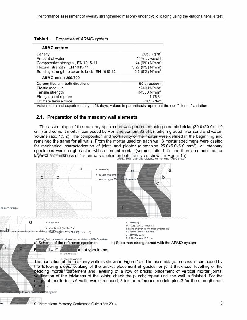
Table 1. Properties of ARMO-system.
ARMO-crete w
Density 2050 kg/m3 Amount of water 14% by weight Compressive strength1, EN 1015-11 44 (6%) N/mm2 Flexural strength1, EN 1015-11 3.27 (6%) N/mm2 Bonding strength to ceramic brick1 EN 1015-12 0.6 (6%) N/mm2
ARMO-mesh 200/200
Carbon fibers in both directions 50 threads/m Elastic modulus ≥240 kN/mm2 Tensile strength ≥4300 N/mm2 Elongation at rupture 1.75 % Ultimate tensile force 185 kN/m
1 Values obtained experimentally at 28 days, values in parenthesis represent the coefficient of variation
2.1. Preparation of the masonry wall elements
The assemblage of the masonry specimens was performed using ceramic bricks (30.0x20.0x11.0 cm3) and cement mortar (composed by Portland cement 32.5N, medium graded river sand and water, volume ratio 1:5:2). The composition and workability of the mortar were defined in the beginning and remained the same for all walls. From the mortar used on each wall 3 mortar specimens were casted for mechanical characterization of joints and plaster (dimension 25.0x5.0x5.0 mm3). All masonry specimens were rough casted with a cement mortar (volume ratio 1:4), and then a cement mortar layer with a thickness of 1.5 cm was applied on both faces, as shown in Figure 1a).
b
e : ARMO-mesh
a
f
abc
de
a : masonryb : rough cast (mortar 1:4)
d : ARMO-crete 12.5 mm
a : alvenaria
b : argamassa
c : rede de carbono
d : argamassa
e : conector
ARMO_Reb : alvenaria reforçada com sistema ARMO-system
_ARMO+C : alvenaria reforçada com sistema ARMO-system e conectores
de
c
c : render layer 15 mn thick (mortar 1:5)
f : ARMO-crete 12.5 mm
a) Scheme of the reference specimen b) Specimen strengthened with the ARMO-system
Figure 1. General layout of specimens.
The execution of the masonry walls is shown in Figure 1a). The assemblage process is composed by the following steps: soaking of the bricks; placement of guides for joint thickness; levelling of the bedding mortar; placement and levelling of a row of bricks; placement of vertical mortar joints; verification of the thickness of the joints; check the plumb; repeat until the wall is finished. For the diagonal tensile tests 6 walls were produced, 3 for the reference models plus 3 for the strengthened models.
a
Ref : alvenaria sem reforço
ARMO_Reb : alvenaria reforçada com sistema ARMO-system
a : masonry
b : rough cast (mortar 1:4)
c : render layer 15 mm thick (mortar1:5)bc
a
venaria sem reforço
Reb : alvenaria reforçada com sistema ARMO-system
a : masonry
b : rough cast (mortar 1:4)
c : render layer 15 mm thick (mortar1:5)bc

ALMEIDA, JOÃO; PEREIRA, EDUARDO; BARROS, JOAQUIM
9th International Masonry Conference, Guimarães 2014 4
2.2. Application of the strengthening systems
The wall models were strengthened using the ARMO-system, which consisted of the following phases: spraying the wall with water; application of the first layer of mortar with an approximate thickness of 1.25 cm; placement of the mesh on top of the mortar layer; application of the second layer of mortar with an approximate thickness of 1.25 cm; use of a ruler and a trowel to level and smoothen the mortar layer surfaces; spraying of the wall surfaces with water 15 min after finished, to avoid shrinkage, see Figure 1b). The strengthening was performed 14 days after application of the plaster.
3 TEST SET UP AND PROCEDURES
Diagonal tensile tests were performed to assess the contribution of the strengthening system to the increasing of the load carrying capacity, corresponding deformation and energy absorption capability of the masonry elements when subjected to a loading scheme which resembles the in-plane shear loading conditions. The specimens presented a square geometry with approximately 106.0 cm side and 14.0 cm or 19.0 cm thickness, reference or strengthened specimens respectively.
The set-up included a testing frame, an actuator with a 500kN load cell, and a Servo-hydraulic closed loop controlled system, a data acquisition system and a monitoring system composed by 5 LVDT’s. The vertical and horizontal displacements at both specimen surfaces were measured in the central area, at ¼ and ¾ of the diagonal length, by using 2 LVDT’s in each direction, see 0a).
The test was performed using displacement control of the actuator cross-head, by measuring the displacement of the cross-head with an external LVDT. The applied displacement rate was kept constant at 0.01 mm/s, for both monotonic and cyclic tests. In the case of the cyclic tests the displacement amplitude was gradually increased until the last cycle was reached. A maximum number of 7 cycles were imposed, plus one last cycle which consisted of applying a monotonically increasing displacement until failure was reached. For the strengthened specimens the 7th cycle was stopped after the loss of contact between the actuator and the loading shoe actuator and the 8th cycle started after, see 0.
The set-up followed strictly the recommendations of ASTM E-519-2, [12]. However, after finalizing the first test the local crushing and splitting of the external strengthening layer was observed at both loading edges of the specimen. To avoid this premature local failure mechanism in the remaining specimens two steel plates were adopted (150x150x30 mm3), which were transversely connected with 16 mm diameter steel rods crossing the specimen between the opposite faces in each support, as shown in 0b).

Performance assessment of overlay strengthened masonry under cyclic loading using the diagonal tensile test
9th International Masonry Conference Guimarães 2014 5
1400
a) Geometry of specimens and position of LVDTs
b) Detail of the test set-up
4 EXPERIMENTAL RESULTS
The results from monotonic diagonal tensile tests, mainly the peak load and corresponding horizontal and vertical average displacements are presented in Table 2. The results from the cyclic tests are presented in Table 3, for each cycle the peak load and corresponding displacement. For specimen ref_03 and armo_03 only the results of 6 and 7 cycles respectively are presented due to the premature failure occurrence at the referred cycles.
Table 2. Monotonic diagonal tensile test results.
0
1
2
3
4
5
6
7
8
9
10
11
12
0 600 1200 1800 2400 3000 3600 4200 4800 5400 6000
Dis
pla
cem
ent (
mm
)
Time (s)
ref_cic_
armo_cic_
Figure 2. Displacement laws imposed during cyclic tests.
Figure 3. Test set-up for the direct tensile test.

ALMEIDA, JOÃO; PEREIRA, EDUARDO; BARROS, JOAQUIM
9th International Masonry Conference, Guimarães 2014 6
ref_02 armo_01
Load (kN)
H. displ (mm)
V. displ (mm)
Load (kN)
H. disp (mm)
V. displ (mm)
97.34 0.12 -0.26 409.54 1.47 -0.68
Table 3. Cyclic diagonal tensile test results.
Cycle
ref_01 ref_03 armo_02 armo_03
Load H. displ.
V. displ.
Load H. displ.
V. displ.
Load H. displ.
V. displ.
Load H. displ.
V. displ.
(kN) (mm) (mm) (kN) (mm) (mm) (kN) (mm) (mm) (kN) (mm) (mm)
1st 15 0.00 -0.02 26 0.02 -0.04 116 0.02 -0.07 83 0.01 -0.05
2nd 43 0.01 -0.06 55 0.03 -0.09 220 0.06 -0.15 198 0.03 -0.12
3th 73 0.03 -0.11 85 0.05 -0.14 340 0.22 -0.29 310 0.11 -0.23
4th 101 0.04 -0.16 110 0.07 -0.18 401 0.78 -0.53 386 0.76 -0.44
5th 116 0.06 -0.19 137 0.10 -0.24 418 1.41 -0.66 431 1.37 -0.71
6th 98 0.13 -0.28 146 0.24 -0.32 383 1.90 -0.79 394 1.63 -0.74
7th 80 0.38 -0.32 -- -- -- 312 2.59 -0.75 315 2.48 -0.46
8th 51 1.33 -0.42 -- -- -- 298 3.07 -1.02 -- -- --
The load vs displacement response of the averaged vertical and horizontal LVDT’s are shown in Figure 4, corresponding to reference and strengthened specimens respectively. These figures show that a sudden failure was obtained at a higher peak load for specimen ref_03. The responses registered for the strengthened specimens are in general similar. Nevertheless, in the case of the monotonic test the displacement corresponding to the ultimate load was found to be lower than in the case of cyclic tests.
Figure 4. Load vs displacement responses of strengthened specimens.

Performance assessment of overlay strengthened masonry under cyclic loading using the diagonal tensile test
9th International Masonry Conference Guimarães 2014 7
The crack patterns observed at the surface of the specimens after testing are presented in 0, where a reference and a strengthened specimen are shown. The reference specimen presents a vertical crack that developed in a straight way from the lower to the upper support. Some additional secondary cracks developed when higher load levels were achieved. The strengthened specimens presented, in a first phase, the same type of cracking as the reference specimens. However, at higher load levels the failure was reached when the strengthening overlay started to detach from the masonry substrate. This detachment occurred at the interface between the traditional mortar and the ceramic masonry brick surface.
a) Crack pattern at the surface of specimen ref_02 b) Detail of the detachment between the strengthening overlay and the substrate observed in specimen armo_02
5 DISCUSSION OF RESULTS
The responses presented in Figure 6 allow to clearly distinguish the different behavior of reference and strengthened walls. The shear strength of strengthened walls is approximately two times higher than the reference walls. Considering the shear strain values obtained there is a wider variability of results in the case of reference specimens. However also the strengthened specimens show considerable scatter. The reason for this variation is related to the failure modes obtained, which are influenced not only by the typical diagonal tensile crack development but also by the detachment of the ARMO-crete layers.
Failure is reached at the reference specimens right after the peak load is reached, and the responses are mostly elastic up to the peak load. In contrast, for the strengthened specimens the load carrying capacity substantially increases. The non-linear part of the responses are much more significant than in the case of the unstrengthened specimens, and the energy dissipation capacity is clearly enhanced.
Figure 5. Crack patterns at the surface of the specimens after diagonal tensile tests.

ALMEIDA, JOÃO; PEREIRA, EDUARDO; BARROS, JOAQUIM
9th International Masonry Conference, Guimarães 2014 8
The average values of shear stress, shear strain and shear modulus are computed in Table 4, as well as the ratio between the limit values of shear stresses and the shear strains for the elastic and for the non-linear branches observed in the reference and the strengthened specimens. From this data is possible to obtain the shear strength increment due to the strengthening system, which is about 2.3.
Table 4. Average of the limit values of the shear stress, shearing strain and shear modulus of the reference and strengthened specimens.
Response range
Type of specimen Shear Stress Shearing Strain Gs
(MPa) (%) (MPa)
Elastic branch
Reference 0.314 0.014 26.059
Strengthened with Armo-system 0.646 0.015 43.297
Ratio: Strengthened/Reference 2.1 1.1 1.7
Near the peak load
Reference 0.871 0.054 16.961
Strengthened with Armo-system 2.002 0.299 6.506
Ratio: Strengthened/Reference 2.3 5.5 0.4
The evolution of the damage due to the cyclic loading is shown in Table 5. The specimens which were strengthened with the ARMO-system present similar residual parameters. In the case of reference specimens the damage occurs in a sudden way In the case of the specimen ref_03 the computed ratio is always 1.0 until the failure, indicating that the specimen fails in a brittle manner.
Figure 6. Shear stress vs shear strain response of the strengthened specimens.
Performance assessment of overlay strengthened masonry under cyclic loading using the diagonal tensile test
9th International Masonry Conference Guimarães 2014 9
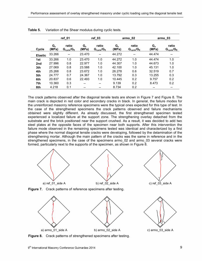
Table 5. Variation of the Shear modulus during cyclic tests.
Cycle
ref_01 ref_03 armo_02 armo_03
Gs (MPa)
ratio Gcycle/GE
Gs (MPa)
ratio Gcycle/GE
Gs (MPa)
ratio Gcycle/GE
Gs (MPa)
ratio Gcycle/GE
Elastic 33.266 -- 23.470 -- 44.272 -- 44.474 --
1st 33.266 1.0 23.470 1.0 44.272 1.0 44.474 1.0
2nd 27.996 0.8 22.977 1.0 44.307 1.0 44.673 1.0
3th 27.069 0.8 23.588 1.0 42.100 1.0 45.131 1.0 4th 25.268 0.8 23.672 1.0 26.278 0.6 32.519 0.7 5th 24.777 0.7 24.367 1.0 13.792 0.3 13.255 0.3
6th 20.837 0.6 22.493 1.0 10.445 0.2 9.757 0.2
7th 10.360 0.3 -- -- 9.139 0.2 8.473 0.2 8th 4.218 0.1 -- -- 8.734 0.2 -- --
The crack patterns observed after the diagonal tensile tests are shown in Figure 7 and Figure 8. The main crack is depicted in red color and secondary cracks in black. In general, the failure modes for the unreinforced masonry reference specimens were the typical ones expected for this type of test. In the case of the strengthened specimens the crack patterns observed and failure mechanisms obtained were slightly different. As already discussed, the first strengthened specimen tested experienced a localized failure at the support zone. The strengthening overlay detached from the substrate and the brick positioned near the support crushed. As a result, it was decided to add two steel plates at the opposite faces of the specimen near both supports. After this intervention the failure mode observed in the remaining specimens tested was identical and characterized by a first phase where the normal diagonal tensile cracks were developing, followed by the delamination of the strengthening mortar. Although the main pattern of the cracks was the same in reference and in the strengthened specimens, in the case of the specimens armo_02 and armo_03 several cracks were formed, particularly next to the supports of the specimen, as shown in Figure 8.
a) ref_01_side A b) ref_02_side A c) ref_03_side A
Figure 7. Crack patterns of reference specimens after testing.
a) armo_01_side A b) armo_02_side A c) armo_03_side A
Figure 8. Crack patterns of strengthened specimens after testing.
ALMEIDA, JOÃO; PEREIRA, EDUARDO; BARROS, JOAQUIM
9th International Masonry Conference, Guimarães 2014 10
6 CONCLUSIONS
Regarding the in-plane diagonal tensile tests, the contribution of the strengthening system to the shear strength increment was about 2.3 times. The evolution of the damage in the specimens while subjected to cyclic loading was in general similar for all strengthened specimens. In the case of reference specimens the damage developed in a sudden manner. In the case of the specimen ref_03 the ratio of 1.0 between the initial modulus of stiffness in shear and the cycle modulus of stiffness in shear remained constant until failure, which revealed the brittle character of the failure mode obtained.
In general the failure modes of the reference specimens, were the typical ones expected for diagonal tensile test. In contrast, the failure modes and crack patterns of the strengthened specimens were characterized by a first phase at which the normal diagonal tensile cracks were developing gradually, followed by the delamination of the strengthening mortar right before failure. Additionally, in the case of the strengthened specimens several cracks were formed, particularly next to the supports of the specimen.
The implementation of the cyclic diagonal tensile test in the experimental characterization of masonry allowed the evaluation of the stiffness rigidity degradation during each cycle. In the other hand it was also possible to verify the capacity of this tests to highlight the most important in-plane rupture mechanisms that commonly occurs in real masonry walls
As conclusion it can be stated that the ARMO-system strengthening technique provided significant additional strength and energy dissipation ability to the strengthened specimens, as well as higher shear strain combined with lower scatter of the obtained results.
Finally it can be stated that the experimental research carried until now permitted to develop and improve skills to perform the characterization of strengthening systems. It was of major importance to understand the plain masonry failure mode and the changes verified when a strengthening overlay system is applied. In the case of in-plane tests it was understood the importance of having elements connecting both faces of the specimens, even when using an improved reinforcing mortar.
ACKNOWLEDGEMENTS
This research was carried in the framework of InoTec, Innovative material of ultra-high ductility for the rehabilitation of the built patrimony, funded by COMPETE/QREN/FEDER (NORTE-07-0202-FEDER-023024). InoTec project is promoted by CiviTest company and University of Minho. S&P Clever Reinforcement Ibérica, is gratefully acknowledged for providing the materials used in the strengthening of the masonry models.
REFERENCES
[1] M. A. Elgawady, P. Lestuzzi, and M. Badoux, “A review of conventional seismic retrofitting techniques for URM,” in 13th International Brick and Block Masonry Conference, 2004, pp. 1–10.
[2] B. Silva, M. Dalla Benetta, F. da Porto, and C. Modena, “Experimental assessment of in-plane behaviour of three-leaf stone masonry walls,” Constr. Build. Mater., vol. 53, pp. 149–161, Feb. 2014.
[3] J. Milosevic, A. S. Gago, M. Lopes, and R. Bento, “Experimental assessment of shear strength parameters on rubble stone masonry specimens,” Constr. Build. Mater., vol. 47, pp. 1372–1380, Oct. 2013.

Performance assessment of overlay strengthened masonry under cyclic loading using the diagonal tensile test
9th International Masonry Conference Guimarães 2014 11
[4] A. Brignola, S. Frumento, S. Lagomarsino, and S. Podestà, “Identification of Shear Parameters of Masonry Panels Through the In-Situ Diagonal Compression Test,” Int. J. Archit. Herit., vol. 3, no. 1, pp. 52–73, Dec. 2008.
[5] A. Borri, G. Castori, M. Corradi, and E. Speranzini, “Shear behavior of unreinforced and reinforced masonry panels subjected to in situ diagonal compression tests,” Constr. Build. Mater., vol. 25, no. 12, pp. 4403–4414, Dec. 2011.
[6] F. Parisi, I. Iovinella, A. Balsamo, N. Augenti, and A. Prota, “In-plane behaviour of tuff masonry strengthened with inorganic matrix – grid composites,” Compos. Part B, vol. 45, no. 1, pp. 1657–1666, 2013.
[7] A. Dehghani, G. Fischer, and F. Alahi, “Strengthening masonry infill panels using engineered cementitious composites,” Mater. Struct., 2013.
[8] N. Ismail, R. B. Petersen, M. J. Masia, and J. M. Ingham, “Diagonal shear behaviour of unreinforced masonry wallettes strengthened using twisted steel bars,” Constr. Build. Mater., vol. 25, no. 12, pp. 4386–4393, Dec. 2011.
[9] A. Borri, G. Castori, and M. Corradi, “Shear behavior of masonry panels strengthened by high strength steel cords,” Constr. Build. Mater., vol. 25, no. 2, pp. 494–503, Feb. 2011.
[10] F. F. S. Pinho, V. J. G. Lúcio, and M. F. C. Baião, “Rubble stone masonry walls in Portugal strengthened with reinforced micro-concrete layers,” Bull. Earthq. Eng., vol. 10, no. 1, pp. 161–180, Apr. 2011.
[11] G. F. M. Vasconcelos and P. B. Lourenço, “Experimental characterization of stone masonry in shear and compression,” Constr. Build. Mater., vol. 23, no. 11, pp. 3337–3345, Nov. 2009.
[12] American Society for Testing and Materials, "E 519-02 Standard test method for diagonal tension (shear) in masonry assemblages." 2002, pp. 1–5.
[13] Comité Européen de Normalisation, “EN 1015-11:1999 Methods of test mortar for masonry – Part 11: Determination of flexural and compressive strength of hardened mortar.” Brussels, 1999.
[14] Comité Européen de Normalisation, “EN 1015-12:2000 Methods of test for mortar for masonry - Part 12: Determination of adhesive strength of hardened mortar.” Brussels, 2000.