performance of recycled plastic pin (rpp) for slope ... · performance of recycled plastic pin...
TRANSCRIPT
Performance of Recycled Plastic Pin(RPP) for Slope Stabilization
M.S. Khan1(&), M. Sahadat Hossain2, M.A. Khan2,and Mohammad Faysal2
1 Department of Civil Engineering, Jackson State University,1400 John R Lynch Street, Jackson, MS 39217, USA
[email protected] Department of Civil Engineering, The University of Texas at Arlington,
416 Yates Street NH 119, Arlington, TX 76019, [email protected], {md.khan22,md.faysal}@mavs.uta.edu
Abstract. Surficial failures of highway slopes in clayey soils are quite commonthroughout the United States. These failures commonly occur for the slopeconstructed with expansive clay, especially after prolonged rainfall. Thesefailures are also predominant in North Texas area and cause significant main-tenance problems for the Texas Department of Transportation (TxDOT). As analternative to the conventional slope stabilization technique, a green and costeffective slope stabilization method using the Recycled Plastic Pin (RPP) hadbeen utilized and tested for its performance. RPPs are driven into the slope faceto provide additional resistance along the slip surface, which increases the factorof safety against shallow slope failure. Current study summarizes the long termperformance of a highway slope on expansive clay reinforced with RPP. Theslope is located over US 287 near the St. Paul overpass in Midlothian, Texas.Surficial movement had taken place over the slope, resulting in cracks over theshoulder and near the bridge abutment. Three 50 ft. slope sections were stabi-lized using RPPs in March 2011. In addition, two 50 ft. unreinforced controlsections were utilized between the reinforced sections to evaluate the perfor-mance of slope sections stabilized with RPP. After installation of the RPPs, theperformance of the slope was monitored by using instrumented RPPs, incli-nometers and topographic survey. The performance monitoring results indicatethat, maximum deformation of the reinforced slope section is less than 3.75 cm(1.5 in.). However, more than 38 cm (15 in.) of vertical settlement was observedat the control sections during the last 5 years monitoring period. Also, fewslope-sections just opposite side of reinforced slope at the same highway failedduring the monitoring period. Based on the last 5 years monitoring data, it wassummarized that RPP can be successfully utilized for slope stabilization.
1 Introduction
Shallow slope failure refers to surficial slope instabilities along highway cuts, fill slopesand embankments. Moderate-to-steep slopes and embankments underlain by expansiveclay soils are susceptible to shallow landslides during intense and prolonged rainfallevents. In many cases, the failure surface is parallel to the slope face. Shallow slope
© Springer International Publishing AG 2018W. Frikha et al. (eds.), Soil Testing, Soil Stability and Ground Improvement,Sustainable Civil Infrastructures, DOI 10.1007/978-3-319-61902-6_12

failures generally do not constitute a hazard to human life or cause major damage.However, they can be a hazard to infrastructure, by causing damage to guardrails,shoulders, road surfaces, drainage facilities, utility poles, and/or the slope landscaping(Titi and Helwany 2007). In some cases, shallow slope failures can affect regular trafficmovement if debris flows onto highway pavements.
Typically, failure occurs because of an increase in pore water pressure and reductionin soil strength due to the progressive wetting of the near-surface soil. This condition isfurther exacerbated by moisture variations due to seasonal climatic changes, whichcause cyclic shrinkage and swelling of the upper soils. Cyclic shrinkage and swellingleads to the change in void ratio of soil and lower the shear strength. Reduction of shearstrength results in sloughing and shallow slope failures which are predominant in theNorth Texas. It poses a significant maintenance problem to the Texas Department ofTransportation (TxDOT) (Wright 2005). The depth of the shallow slope failure varieswith soil type and slope geometry, but generally ranges between 0.9 m (3 ft.) and 1.8 m(6 ft.). (Loehr et al. 2007). Shallow failures often cause significant hazards to guard rails,shoulders, and roadways, which, if not properly maintained, may require extensive andexpensive repairs.
Reinforcement is an effective remediation technique for relatively shallow slopefailure conditions. In situ reinforcement methods for stabilizing slopes and embank-ments include soil nails, drilled piers, micro piles, and RPPs (Thompson et al. 2006).Among the available methods, the RPPs have been recognized as a cost effectivesolution for slope stabilization (Loehr and Bowders 2007; Khan et al. 2015). RPPswere first being utilized in the state of Missouri and Iowa, as a sustainable option tostabilize highway slopes and few field studies were conducted. The study summarizedthat no further failure was noticed after the slopes were stabilized using RPPs and theperformance of the stabilized zone was promising (Loehr and Bowders 2007).
Typically, RPPs are fabricated from recycled plastics and waste materials (polymers,sawdust, and fly ash) (Chen et al. 2007). It is a lightweight material and less susceptibleto chemical and biological degradation than other reinforcement materials. The use ofRPPs can reduce the waste volume entering landfills and provide additional demand forrecycled plastic (Sommers et al. 2000). A typical RPP is composed of High DensityPolyethylene, HDPE (55%–70%); Low Density Polyethylene, LDPE (5%–10%);Polystyrene, PS (2%–10%); Polypropylene, PP (2%–7%); Polyethylene-terephthalate,PET (1%–5%); and varying amounts of additives, i.e., sawdust, fly ash (0%–5%)(McLaren 1995). The use of glass and wood fiber additives significantly improves themodulus of elasticity for plastic lumber (Breslin et al. 1998). RPPs driven into the slopeface may provide an additional resistance along the slip plane that restricts the pro-gression of the slip surface and increases the factor of safety. However, limited fieldstudies have been conducted on the potential use of RPPs in slope stabilization.
The current study presents the long term performance of RPP for a highway slopestabilization. Surficial movement and a cracked shoulder were observed on a highwayslope located over highway US 287 in Texas. During March 2011, two 15.25 m (50 ft.)sections on the southbound side of US 287 were reinforced using RPPs. Anothercracked zone formed over the shoulder of US 287 during the following year, and a new15.25 m (50 ft.) section was reinforced considered on the southbound slope for thestabilization, using RPPs. In addition, two 15.25 m (50 ft.) control sections were kept
Performance of Recycled Plastic Pin (RPP) for Slope Stabilization 137
between the reinforced sections to compare the performance. The reinforced andcontrol sections of the slope were monitored after installation to evaluate the perfor-mance of the slope, using instrumented RPPs, inclinometers and surveying equipment.
2 Project Background
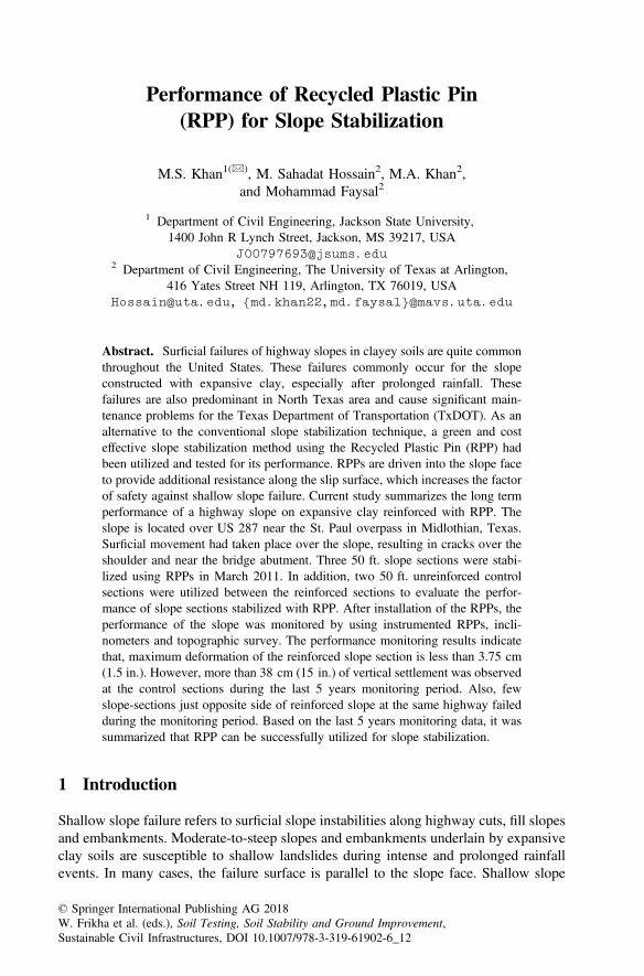
The slope is located near Highway US 287, near the St. Paul overpass in Midlothian,Texas. It is a 3(H): 1(V) fill slope with 30 ft. height. Surficial movement over the slopeand shoulder cracks were observed on the shoulder near the crest of the slope inSeptember, 2010. The cracks along the pavement shoulder might have occurred due tothe surficial movement of the slope. The site location and the photo of the crackedshoulder are presented in Fig. 1.
The geology of the location is characterized by the Eagle Ford formation. TheEagle Ford, in the project vicinity, is composed of residual soils, consisting of clay andweathered shale (shaly clay), underlain by unweathered shale. The weathered shale isclaylike and contains gypsum in-fills, jointed and fractured with iron pyrites. Theunweathered shale is typically gray to dark gray and commonly includes shell debris,silty fine sand particles, bentonite and pyrite. The Eagle Ford formation consists ofsedimentary rock in the process of degrading into a soil mass. This formation alsocontains smectite clay minerals and sulfates. The smectite clay minerals are highlyexpansive in nature and may be a contributing factor to the expansiveness of the soil.A previous study by Kibria and Hossain (2012) indicated that the dominant mineral ofthe soil is montmorillonite mineral, which has high shrink/swell.
A field exploration program was undertaken, which indicated that the slope wasconstructed with high plastic clayey (CH) soil. The liquid limits (LL) and plasticityindices (PI) of the samples ranged between 48 to 79 and 25 to 51, respectively. Inaddition, an increase in moisture below 5 ft. was observed, which ranged up to 20 ft.Based on the back analysis with PLAXIS 2D the factor of safety was 1.05 with fullysoften shear strength (Khan et al. 2015).
(a) (b)
Fig. 1. (a) Site location (b) Cracks along the shoulder of Highway US 287
138 M.S. Khan et al.
3 Slope Stabilization Using RPP
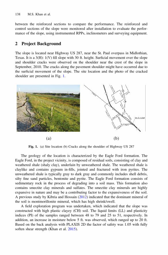
The definition of the factor of safety of a slope is the ratio of resisting moment (MR) tothe driving moment (MD), as presented in Eq. 1. RPPs installed at the slope providedan additional resisting moment (DMR) along the slip surface, thereby increasing theresistance and factor of safety, as presented in Eq. 2. The schematic diagram of RPPsas slope reinforcement is presented in Fig. 2.
FS ¼ MR=MD ð1Þ
FS ¼ MR þDMRð Þ=MD ð2Þ
Where,MR = Resisting Moment along Slip SurfaceMD = Driving Moment along Slip SurfaceDMR = Additional Resisting Moment from Plastic Pin.
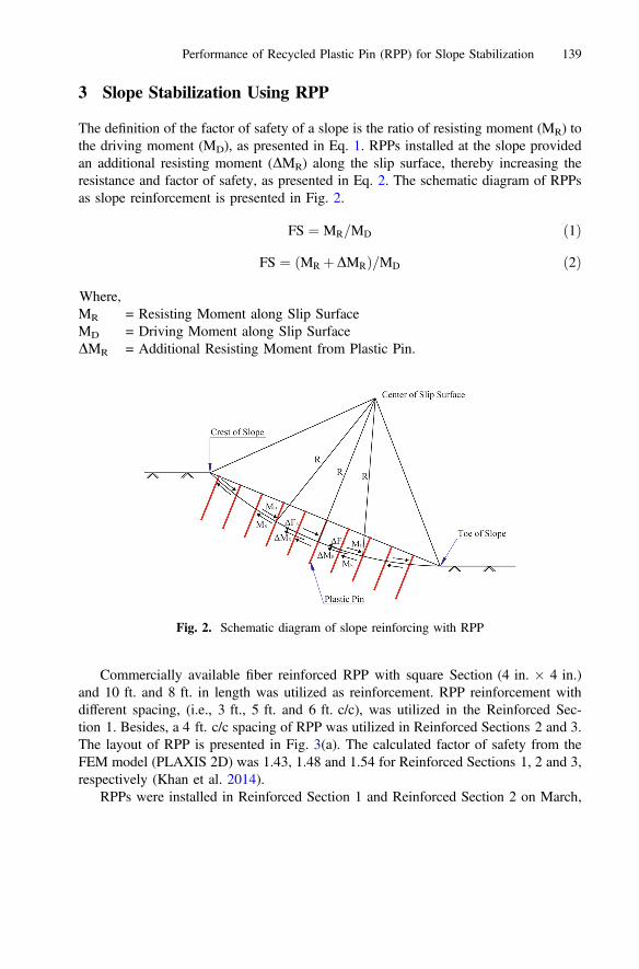
Commercially available fiber reinforced RPP with square Section (4 in. � 4 in.)and 10 ft. and 8 ft. in length was utilized as reinforcement. RPP reinforcement withdifferent spacing, (i.e., 3 ft., 5 ft. and 6 ft. c/c), was utilized in the Reinforced Sec-tion 1. Besides, a 4 ft. c/c spacing of RPP was utilized in Reinforced Sections 2 and 3.The layout of RPP is presented in Fig. 3(a). The calculated factor of safety from theFEM model (PLAXIS 2D) was 1.43, 1.48 and 1.54 for Reinforced Sections 1, 2 and 3,respectively (Khan et al. 2014).
RPPs were installed in Reinforced Section 1 and Reinforced Section 2 on March,
Fig. 2. Schematic diagram of slope reinforcing with RPP
Performance of Recycled Plastic Pin (RPP) for Slope Stabilization 139
2011, as presented in Fig. 3(b). Reinforced Section 3 was stabilized during March,2012. A crawler-type drilling rig, having a mast-mounted vibrator hammer (model:Klemm 802 drill rig along with KD 1011 percussion head drifter), was utilized toinstall the RPPs. The crawler-type rig was suitable for the installation process over theslopes, as no additional anchorage was required to maintain the stability of theequipment, reducing labor, cost and time involved in the installation process. Based on
(a)
(b)
Fig. 3. (a) Layout of RPP at US 287 slope (b) Installation photo
140 M.S. Khan et al.
the study, the average installation time for a 10 ft. long RPP was 4 min, and a total of100 to 120 RPPs could be installed in one day.
4 Instrumentation and Performance Monitoring
Regular topographic survey and inclinometers were used to monitor the performance ofRPP stabilized slope. To evaluate the performance of the reinforced slopes and tomonitor the horizontal displacement, inclinometers were installed after the completionof field installation in Reinforced Section 1 and Reinforced Section 2.
4.1 Topographic Survey
To compare the performance between the reinforced section and control section,topographic surveys were performed on monthly basis. The purpose of this survey wasto monitor the settlement of the crest of the slope.
4.2 Inclinometers
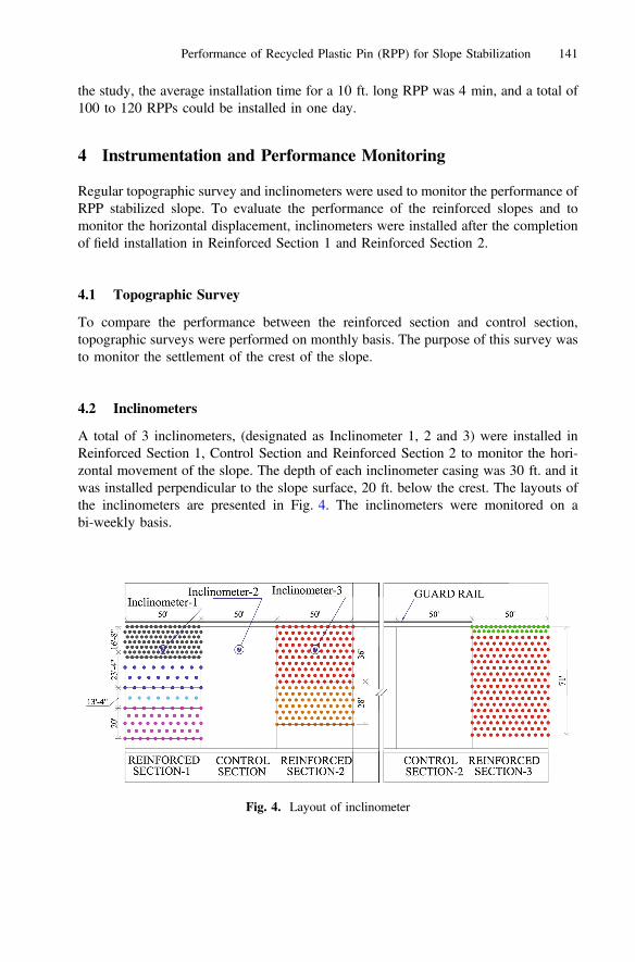
A total of 3 inclinometers, (designated as Inclinometer 1, 2 and 3) were installed inReinforced Section 1, Control Section and Reinforced Section 2 to monitor the hori-zontal movement of the slope. The depth of each inclinometer casing was 30 ft. and itwas installed perpendicular to the slope surface, 20 ft. below the crest. The layouts ofthe inclinometers are presented in Fig. 4. The inclinometers were monitored on abi-weekly basis.
Fig. 4. Layout of inclinometer
Performance of Recycled Plastic Pin (RPP) for Slope Stabilization 141
5 Performance Evaluation
5.1 Topographic Survey
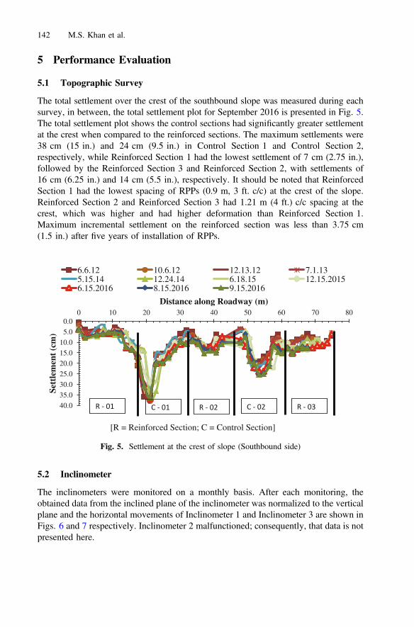
The total settlement over the crest of the southbound slope was measured during eachsurvey, in between, the total settlement plot for September 2016 is presented in Fig. 5.The total settlement plot shows the control sections had significantly greater settlementat the crest when compared to the reinforced sections. The maximum settlements were38 cm (15 in.) and 24 cm (9.5 in.) in Control Section 1 and Control Section 2,respectively, while Reinforced Section 1 had the lowest settlement of 7 cm (2.75 in.),followed by the Reinforced Section 3 and Reinforced Section 2, with settlements of16 cm (6.25 in.) and 14 cm (5.5 in.), respectively. It should be noted that ReinforcedSection 1 had the lowest spacing of RPPs (0.9 m, 3 ft. c/c) at the crest of the slope.Reinforced Section 2 and Reinforced Section 3 had 1.21 m (4 ft.) c/c spacing at thecrest, which was higher and had higher deformation than Reinforced Section 1.Maximum incremental settlement on the reinforced section was less than 3.75 cm(1.5 in.) after five years of installation of RPPs.
5.2 Inclinometer
The inclinometers were monitored on a monthly basis. After each monitoring, theobtained data from the inclined plane of the inclinometer was normalized to the verticalplane and the horizontal movements of Inclinometer 1 and Inclinometer 3 are shown inFigs. 6 and 7 respectively. Inclinometer 2 malfunctioned; consequently, that data is notpresented here.
[R = Reinforced Section; C = Control Section]
0.0
5.0
10.0
15.0
20.0
25.0
30.0
35.0
40.0
0 10 20 30 40 50 60 70 80
Sett
lem
ent (
cm)
Distance along Roadway (m)
6.6.12 10.6.12 12.13.12 7.1.135.15.14 12.24.14 6.18.15 12.15.20156.15.2016 8.15.2016 9.15.2016
R - 01 C - 01 R - 02 C - 02 R - 03
Fig. 5. Settlement at the crest of slope (Southbound side)
142 M.S. Khan et al.

The comparisons of movement between Inclinometer 1 and Inclinometer 3 atdifferent depths (1.37 m and 3.2 m) are presented in Fig. 8. It was observed thatInclinometer 3 had higher horizontal displacement (4.3 cm) than Inclinometer 1(2.8 cm) at 1.37 m depth. A similar trend was observed at 3.2 m depth, where theobserved displacement was 3.9 cm and 1.6 cm for Inclinometer 1 and Inclinometer 3,respectively. It should be noted that the maximum horizontal displacement took placeat the surface of the slope and consequently reducing with deeper depth.
Fig. 6. Inclinometer - 1: cum displacement A-A with time
Fig. 7. Inclinometer - 3: cum displacement A-A with time
Performance of Recycled Plastic Pin (RPP) for Slope Stabilization 143

Khan et al. 2014 conducted a numerical study on the slope stabilization usingrecycled plastic pin. During the study, the change in horizontal displacement of RPP atthe crest of the slope is investigated using finite element method (FEM), with thechange in RPP spacing. The FEM results indicated that, with the increment in RPPspacing from 0.2 m (2 ft.) to 2.4 m (8 ft.), the horizontal displacement of RPPincreases from 2.5 cm (1 in.) to 12 cm (4.7 in.). In addition, the observed horizontaldisplacement from FEM analysis at the crest is in good agreement with the observeddisplacement at the field with 0.9 m (3 ft.) and 1.2 m (4 ft.) spacing.
5.3 Performance of the Northbound Slope
The northbound slope of highway US 287 was inspected visually on a monthly basisfor last five years. A number of shallow slope failures were recorded on the control(northbound of US 287) slope and the failure locations are shown in Fig. 9. Pho-tographs of the failures of Location 1 to Location 6 are also shown in Fig. 10. First timefailures (Location 1 and Location 2) on the control slope were observed duringSeptember 2013, after a rainfall event. Soil was backfilled and compacted within thefailure zone during the maintenance period. But the slope failed (Location 3) againduring August, 2014 after a period of a heavy rainfall. Soil was backfilled again within
Fig. 8. Comparison of inclinometer - 1 & 3
144 M.S. Khan et al.
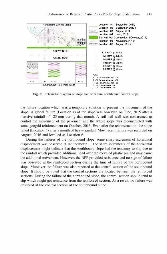
the failure location which was a temporary solution to prevent the movement of theslope. A global failure (Location 4) of the slope was observed on June, 2015 after amassive rainfall of 125 mm during that month. A soil nail wall was constructed tocontrol the movement of the pavement and the whole slope was reconstructed withsome geogrid reinforcement on October, 2015. Even after the reconstruction, the slopefailed (Location 5) after a month of heavy rainfall. Most recent failure was recorded onAugust, 2016 and levelled as Location 6.
During the failures of the northbound slope, some sharp increment of horizontaldisplacement was observed at Inclinometer 1. The sharp increments of the horizontaldisplacement might indicate that the southbound slope had the tendency to slip due tothe rainfall which provided additional load over the recycled plastic pin and may causethe additional movement. However, the RPP provided resistance and no sign of failurewas observed at the reinforced section during the time of failure of the northboundslope. Moreover, no failure was also reported at the control section of the southboundslope. It should be noted that the control sections are located between the reinforcedsections. During the failure of the northbound slope, the control section should tend toslip which might get resistance from the reinforced section. As a result, no failure wasobserved at the control section of the southbound slope.
Fig. 9. Schematic diagram of slope failure within northbound control slope.
Performance of Recycled Plastic Pin (RPP) for Slope Stabilization 145

6 Summary
A highway slope located on the southbound side of highway US 287 near the St. Pauloverpass in Midlothian, Texas was stabilized using RPPs. Three 15.25 m (50 ft.)sections were selected and reinforced, using RPPs, after a crack, caused by slopemovement, was observed on the shoulder. Additionally, two 15.25 m (50 ft.) controlsections were utilized between the reinforced sections to compare the performancesbetween the unreinforced and reinforced slopes. The field performance of the slope wasmonitored using topographic survey and inclinometers. Performance monitoring resultsfor last 5 (five) years are summarized below.
Location – 01 (September, 2013) Location – 02 (September, 2013)
Location – 03 (August, 2014) Location – 04 (June, 2015)
Location – 05 (November, 2015) Location – 06 (August, 2016)
Fig. 10. Failure locations (Location 01–06) at the northbound of the US 287 slope
146 M.S. Khan et al.

• The unreinforced control sections of the southbound slope had significant settle-ment at the crest of the slope, as much as 38 cm whereas the incremental settlementon the reinforced section was less than 3.75 cm.
• Maximum cumulative displacement for inclinometer 1, at a depth below 1.37 and3.20 m were 2.80 cm and 1.60 cm respectively.
• Maximum cumulative displacement for inclinometer 3, at a depth below 1.37 and3.20 m were 4.30 cm and 3.90 cm respectively.
• Both inclinometers showed the same trend that, cumulative displacement decreaseswith the depth from the slope surface.
• Having the same geographic and climatic condition, the southbound control slopefailed several times at different locations.
Based on the current study, it can be concluded that the overall performance of thereinforced sections was better than that of the control sections. The northbound controlslope failed several times during the monitoring period whereas no visual depression orfailure was observed within the southbound slope. Since the shallow failure is a majorissue for slopes constructed with high plastic clayey soil; RPPs could provide a costeffective and sustainable solution to mitigate this problem.
References
Breslin, V.T., Senturk, U., Berndt, C.C.: Long-term engineering properties of recycled plasticlumber in pier construction. Resour. Conserv. Recycl. 23(1998), 243–258 (1998)
Chen, C.W., Salim, H., Bowders, J., Loehr, E., Owen, J.: Creep behavior of recycled plasticlumber in slope stabilization applications. J. Mater. Civ. Eng. 19(2), 130–138 (2007)
Khan, M.S., Hossain, S., Kibria, G.: Stabilisation using recycled plastic pins. J. Perform.Constructed Facil. 229–234 (2017). doi:10.1201/9781315206202-11. Online publication date:14 Jun 2017
Khan, M.S., Hossain, M., Lozano, N.: Numerical study of slope stabilization using recycledplastic pin. In: Geo-Congress 2014 Technical Papers: Geo-characterization and Modeling forSustainability, pp. 3092–3101. ASCE, February 2014
Kibria, G., Hossain, M.S.: Investigation of geotechnical parameters affecting electrical resistivityof compacted clays. J. Geotech. Geoenviron. Eng. (2012). doi:10.1061/(ASCE)GT.1943-5606.0000722
Loehr, J.E., Bowders, J.J.: Slope Stabilization using Recycled Plastic Pins – Phase III. Finalreport: RI98-007D, Missouri Department of Transportation, Jefferson City, Missouri (2007)
Loehr, J.E., Fennessey, T.W., Bowders, J.J.: Stabilization of surficial slides using recycled plasticreinforcement. Transp. Res. Rec. J. Transp. Res. Board 2, 79–87 (2007). No. 1989
McLaren, M.G.: Recycled plastic lumber and shapes design and specification. In: Proceedings13th Structures Congress, ASCE, vol. 1, pp. 819–833 (1995)
Sommers, L., Loehr, J.E., Bowders, J.J.: Construction methods for slope stabilization withrecycled plastic pins. In: Proceedings of the Mid-continent Transportation Symposium, IowaState University, Ames, Iowa, 15–16 May 2000
Thompson, M.J., White, D.J.: Design of reinforcement with small-diameter piles. In: Proceedingsof Advances in Earth Structures: Research to Practice, GSP no. 151, pp. 1–12 (2006).Reston/VA
Performance of Recycled Plastic Pin (RPP) for Slope Stabilization 147

Titi, H., Helwany, S.: Investigation of Vertical Members to Resist Surficial Slope Instabilities(No. WHRP 07-03). Wisconsin Department of Transportation, Madison, WI (2007)
Wright, S.G.: Evaluation of Soil Shear Strengths for Slope and Retaining Wall Stability Analyseswith Emphasis on High Plasticity Clays. Federal Highway Administration, Washington, D.C.(2005). FHWA/TX-06/5-1874-01-1
148 M.S. Khan et al.