performance of cryogenically treated hss tools
DESCRIPTION
technical paperTRANSCRIPT

A
siiam©
K
1
atdeiHtbatt
(e(
0d
Wear 261 (2006) 674–685
Performance of cryogenically treated HSS tools
Flavio J. da Silva a, Sinesio D. Franco b,∗, Alisson R. Machado c, Emmanuel O. Ezugwu d,Antonio M. Souza Jr. e
a Federal University of Espırito Santo, Technological Center, Department of Mechanical Engineering, 29.060-970 Vitoria, ES, Brazilb Federal University of Uberlandia, Faculty of Mechanical Engineering, Tribology and Materials Laboratory,
LTM, 38.400-089 Uberlandia, MG, Brazilc Federal University of Uberlandia, Faculty of Mechanical Engineering, Machining Teaching and Research Laboratory,
LEPU, 38.400-089 Uberlandia, MG, Brazild London South Bank University, Machining Research Laboratory, Department of Engineering Systems, London, UK
e Fiat-GM Powertrain, F.A. Powertrain Ltd., Engineering Manufacturing, Betim, MG, Brazil
Received 13 March 2005; received in revised form 23 January 2006; accepted 24 January 2006Available online 10 March 2006
bstract
Studies on cryogenically treated high speed steel tools show microstructural changes in the material that can influence tool lives and productivityignificantly. Results in the literature show tool life improvements from 92% to 817% when using the cryogenically treated HSS tools in thendustry. However, the real mechanisms which guarantee better tool performance are still dubious. This implies in the need of further investigation
n order to control the technique more scientifically. This work aims to verify the effect of cryogenic treatment on M2 high speed steel toolsfter using either laboratories or shop floor tests in an automotive industry. Sliding abrasion and hardness tests were also carried out as well asicrostructural analysis. Advantages were found for the treated tools in some of these tests.2006 Elsevier B.V. All rights reserved.ity; W
Hnmarat
bt
eywords: High speed steel tools; Cryogenic treatment; Improving machinabil
. Introduction
The need to develop more and more resistant tool materi-ls able to cut increasingly resistant workpiece materials andhe demand of the technological development for higher pro-uctivity and lower costs have caused many tool materials withxcellent properties such as cemented carbide, cermets, ceram-cs and ultra hard materials (CBN, PCBN and PCD) to emerge.igh speed steel (HSS) can also be included in this list since this
ool material is fairly well used in the industry to date, althougheing developed more than a century ago. Its main applications
re for drills, taps, milling cutters, broaches and also bits wherehe economical cutting speed is too low to think about carbideools [1].∗ Corresponding author. Tel.: +55 34 3239 4186; fax: +55 34 3239 4272.E-mail addresses: [email protected] (F.J. da Silva), [email protected]
S.D. Franco), [email protected] (A.R. Machado),[email protected] (E.O. Ezugwu), [email protected]. Souza Jr.).
abrRt
grt
043-1648/$ – see front matter © 2006 Elsevier B.V. All rights reserved.oi:10.1016/j.wear.2006.01.017
ear behaviour
With the time, since their creation, the properties of theSS tools were considerably improved. The perfect combi-ation of alloying elements and the domain of heat treat-ent processes conferred to this material excellent hardness
nd wear resistance properties allied to good toughness. As aesult of technological advance a great variety of HSS toolsre actually available, including coated and powder metallurgyools.
In recent decades interest in low temperature effects haveeen demonstrated particularly during heat treating cycles ofool steels. Some literature data indicates that the lives of toolsnd other steel components may increase significantly aftereing submitted to subzero (below 0 ◦C) temperatures. Theesults can be surprisingly good, depending on the application.eports of 92–817% increases in tool lives after they have being
reated at −196 ◦C are found [2].
Unlike coatings that are only a superficial treatment, the cryo-enic treatment is applied to the whole volume of the material,eaching the core of the tools. This guarantees maintenance ofheir properties even after regrinding or resharpening. However,

ear 261 (2006) 674–685 675
tartds
tegp
tamtontp
drssfbmsmtwim
tftpsdpwBtcftattm
iTpt
Table 1Various kinds of heat treatment studied by Alexandru et al. [13]
A Quenching 1230 ◦CB Quenching 1230 ◦C + double tempering 560 ◦CC Quenching 1230 ◦C + sub-zero (−70 ◦C)G Quenching 1230 ◦C + sub-zero (−70 ◦C) + tempering 560 ◦CH Quenching 1230 ◦C + tempering 560 ◦C + sub-zero (−70 ◦C)M Quenching 1230 ◦C + tempering 560 ◦C + sub-zero (−70 ◦C) +
tempering 560 ◦CN Quenching 1230 ◦C + tempering 560 ◦C + sub-zero (−70 ◦C) +
tempering 560 ◦C + sub-zero (−70 ◦C) + tempering 560 ◦C
Route A (%) M (%) C (%) NC T (min)
A 42.6 66.6 6.9 – –B 12.8 74.6 12.5 23410.24 22C 7.5 84.9 7.6 – 38G 2.2 85.3 12.5 30928.49 49H 13.3 71.2 15.5 23788.52 47M 1.6 19.9 18.5 42869.81 51N
A1
cs
bTsdrnc
iMp[sa
qaaraTst
rdfb
F.J. da Silva et al. / W
he lack of common sense in the literature regarding to the met-llurgical aspects that cryogenic treatment confers better wearesistance and consequently higher tool lives as well as con-radictory results that are also encountered [3–5] lead to manyoubts and questions involving the practical application of thisort of treatment.
The articles found in the literature about this subject varyremendously from mere promotional information until full sci-ntific publication. The latter kind of articles may offer metallur-ical details and the mechanisms that will guarantee improvedroperties of the tools.
The first users of this technique [6] applied temperatures inhe range of −80 to −100 ◦C for periods of about 30 min–1 h,nd the improvement on tool life was credited to the transfor-ation of retained austenite (softer) into martensite (harder) and
he production of a more stable structure. In general the additionf alloying elements lowers the Ms (temperature of the begin-ing of martensite transformation) and Mf (final transformationemperature) lines in a way that the latter dwells at subzero tem-eratures.
The conventional heat treatment normally uses cooling con-itions only until room temperature, which may leave someetained austenite on the microstructure. This fact must be con-idered during heat treatment of tool steels. For the eutectoidteel the Mf temperature is of approximately of −50 ◦C, there-ore after quenching some percentage of retained austenite wille present [8]. Lately this structure can be transformed intoartensite if the material is submitted to reheating or to a
tress field, causing distortion on its body. This non-temperedartensite may cause cracks, particularly in complex shape
ools made of highly alloyed steels [9]. The subzero treatmentill transform a great deal of this retained austenite by reach-
ng the Mf line, giving more dimensional stability in the toolicrostructure.Barron [10] has attributed the improvement of the wear resis-
ance of these tools to another mechanism besides the trans-ormation of the retained austenite into martensite. He verifiedhat the tool steels submitted to conventional heat treatmentresented only a small amount of retained austenite, but thoseubmitted to cryogenic treatment showed better performanceuring machining. This new mechanism would be time and tem-erature dependent due to the long period (8 h or more) duringhich the tools would have to stay at cryogenic temperatures.efore the cryogenic treatment the microstructure showed rela-
ively large carbides (20 �m) dispersed in the matrix. After theryogenic treatment, carbide particles as small as 5 �m wereound. The carbide refinement could in such a way contribute tohe improvement of the wear resistance of the tool. Barron thusttributed this achievement both to austenite transformation ando the presence of hard and small carbide particles well dis-ributed among the larger carbide particles within the martensite
atrix.Popandopulo and Zhukova [11] carried out dilatometry stud-
es and microstructure analysis during cryogenic treatment.hey observed volume reduction of the specimen at the tem-erature range of −90 to +20 ◦C. This behaviour was attributedo partial decomposition of the martensite and precipitation of
ittt
0.9 81.7 17.4 69646.09 45
: austenite; M: martensite; C: carbides; NC: amount of carbides smaller than�m/mm; T: tool life.
arbon atoms at dislocation lines and formation of ultramicro-copic carbides.
Paulin [2] also verified the presence of fine precipitated car-ide particles and their importance to the material properties.he precipitated carbides reduce internal tension of the marten-ite and minimize microcracks susceptibility, while the uniformistribution of fine carbides of high hardness enhances the wearesistance. Huang et al. [12] confirmed that cryogenic treatmentot only facilitate the carbide formation but can also make thearbide distribution more homogeneous.
The main variables during heat treatment have a great deal ofnfluence on the results. A research done in steels equivalent to
2, varying the cryogenic cycles has quantified the precipitatedarticles and verified their influence onto the material properties13]. Their research involved seven steel samples, each of themubmitted to different heating and cooling (up to −70 ◦C) cycless described in Table 1.
The microstructure was analysed and the carbide particlesuantified using SEM, X-ray difractometer, quantitative met-llography and differential dilatometer. The results confirmedn increase in carbide precipitation (from 6.9% to 17.4%), aeduction of the retained austenite (from 42.6% to 0.9%) andn increase in the martensite content (from 66% to 81.7%).he machining tests carried out with bits in turning AISI 1050teels showed a significant increase in tool lives of cryogenicallyreated tools (Table 1).
These results can be attributed to minimum quantity ofetained austenite, higher amount of martensite content, higherensity of fine carbides (smaller than 1 �m) and a moreavourable distribution of the alloying elements among the car-ide of the matrix.
Barron [14] after cryogenically treating several materials
ncluding the M2 high speed steel at −84 ◦C (maintaining it athis temperature for 24 h) observed a significant improvement onhe wear resistance in sliding abrasion tests [15] when comparedo conventionally heat treated steel (quenched and tempered).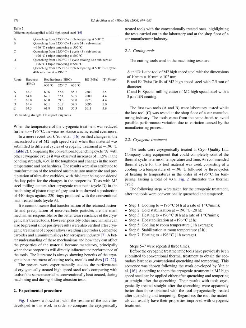
676 F.J. da Silva et al. / Wear 2
Table 2Different cycles applied to M2 high speed steel [16]
A Quenching from 1250 ◦C + triple tempering at 560 ◦CB Quenching from 1250 ◦C + 1 cycle 24 h sub-zero at
−196 ◦C + triple tempering at 560 ◦CC Quenching from 1250 ◦C + 1 cycle 48 h sub-zero at
−196 ◦C + triple tempering at 560 ◦CD Quenching from 1250 ◦C + 3 cycle totaling 48 h sub-zero at
−196 ◦C + triple tempering at 560 ◦CE Quenching from 1250 ◦C + triple tempering at 560 ◦C+ 1 cycle
48 h sub-zero at −196 ◦C
Route Hardness(HRC)
Red hardness (HRC) BS (MPa) IT (J/mm2)
600 ◦C 625 ◦C 630 ◦C
A 63.7 60.6 57.8 55.7 2583 3.5B 64.8 62.1 57.1 57.5 2880 4.4C 65.0 63.0 59.3 58.0 2873 4.4D 65.4 63.1 61.7 59.5 3096 5.0E
B
Wf
ms(obttctsmoh
imgagcttwtg
otm
2
d
ttc
2
ttpm
2
Cttcopc
a
•••••••
sosasog
64.3 61.8 58.1 57.3 2611 3.9
S: bending strength; IT: impact toughness.
hen the temperature of the cryogenic treatment was reducedurther to −196 ◦C, the wear resistance was increased even more.
In a more recent work Yun et al. [16] verified changes in theicrostructure of M2 high speed steel when this material was
ubmitted to different cycles of cryogenic treatment at −196 ◦CTable 2). Comparing the conventional quenching cycle “A” withther cryogenic cycles it was observed increases of 11.5% in theending strength, 43% in the toughness and changes in the roomemperature and hot hardness. The results were also attributed toransformation of the retained austenite into martensite and pre-ipitation of ultra-fine carbides, with this latter being consideredhe key point for the changes in the properties. Tests with M2teel milling cutters after cryogenic treatment (cycle D) in theachining of piston rings of grey cast iron showed a production
f 440 rings against 220 rings produced with the conventionaleat treated tools (cycle A).
It is common sense that transformation of the retained austen-te and precipitation of micro-carbide particles are the main
echanism responsible for the better wear resistance of the cryo-enically treated tools. However, possibly other mechanisms canlso be present since positive results were also verified after cryo-enic treatment of copper alloys (welding electrodes), cementedarbides and aluminium alloys for aerospace industry [7]. A bet-er understanding of these mechanisms and how they can affecthe properties of the material become mandatory, principallyhen these properties will directly influence the performance of
he tools. The literature is always showing benefits of the cryo-enic heat treatment of cutting tools, moulds and dies [17–22].
The present work experimentally studies the performancef cryogenically treated high speed steel tools comparing withools of the same material but conventionally heat treated, during
achining and during sliding abrasion tests.
. Experimental procedure
Fig. 1 shows a flowchart with the resume of the activitieseveloped in this work in order to compare the cryogenically
baat
61 (2006) 674–685
reated tools with the conventionally treated ones, highlightinghe tests carried out in the laboratory and at the shop floor of aar manufacturer industry.
.1. Cutting tools
The cutting tools used in the machining tests are:
A and D: Lathe tool of M2 high speed steel with the dimensionsof 10 mm × 10 mm × 102 mm.B and E: Twist Drills of M2 high speed steel with 7.5 mm ofdiameter.C and F: Special milling cutter of M2 high speed steel with a3 �m TiN coating.
The first two tools (A and B) were laboratory tested whilehe last tool (C) was tested at the shop floor of a car manufac-uring industry. The tools came from the same batch to avoidossible performance variation due to variation caused by theanufacturing process.
.2. Cryogenic treatment
The tools were cryogenically treated at Cryo Quality Ltd.ompany using equipment that could completely control the
hermal cycle in terms of temperature and time. A recommendedhermal cycle for this tool material was used, consisting of aooling to a temperature of −196 ◦C followed by three cyclesf heating to temperatures in the order of +196 ◦C for tem-ering, lasting a total of 43 h. Fig. 2 illustrates this thermalycle.
The following steps were taken for the cryogenic treatment,fter the tools were conventionally quenched and tempered:
Step 1: Cooling to −196 ◦C (4 h at a rate of 1 ◦C/mim);Step 2: Cold stabilization at −196 ◦C (20 h);Step 3: Heating to +196 ◦C (8 h at a rate of 1 ◦C/mim);Step 4: Hot stabilization at +196 ◦C (2 h);Step 5: Cooling to room temperature (1 h average);Step 6: Stabilization at room temperature (2 h);Step 7: Heating to +196 ◦C (1 h average).
Steps 5–7 were repeated three times.Before the cryogenic treatment the tools have previously been
ubmitted to conventional thermal treatment to obtain the sec-ndary hardness (conventional quenching and tempering). Thisequence was chosen following the work developed by Yun etl. [16]. According to them the cryogenic treatment in M2 highpeed steel can be applied either after quenching and temperingr straight after the quenching. Their results with tools cryo-enically treated straight after the quenching were apparently
etter than those obtained with the tool cryogenically treatedfter quenching and tempering. Regardless the rout the materi-ls can usually have their properties improved with cryogenicreatment.
F.J. da Silva et al. / Wear 261 (2006) 674–685 677
sts ca
2
22wt
a
Fig. 1. Experimental te
.3. Laboratory tests
.3.1. Lathe tools—bits
.3.1.1. Microstrutural analysis and hardness. This part of theork had the objective of analysing the changes that occurred in
he microstructure of the M2 steel after the cryogenic treatment.
Fig. 2. Processing routes of the cryogenic treatment.
Ecta
tihoic
2ldactac
rried out in this work.
The percentages of the retained austenite for both treatednd untreated steels were determined according to the ASTM
975-03 [23] standard, using an X-ray difractometer. Theontent of carbide not dissolved during austenitisation wasaken into consideration in determining the amount of retainedustenite.
The hardness (HRc) was measured on three cryogenicallyreated samples and on three non-treated samples with a min-mum of four indentations in each. The Vickers HV0.1 micro-ardness was measured on one sample cryogenically treated andn one sample non-treated with a minimum of ten indentationsn each. The average of these measurements was considered foromparison.
.3.1.2. Brandsma (1936) rapid facing tests. This is a shortasting test based on tool life which consists of face turning aisc from the center towards the periphery with spindle rotationnd feed rate constants as depicted in Fig. 3. It starts with a small
utting speed vc1, corresponding to the diameter of the hole athe center of the disk reaching a much higher cutting speed vc2t the end of the test, defined by a complete destruction of theutting edge [24].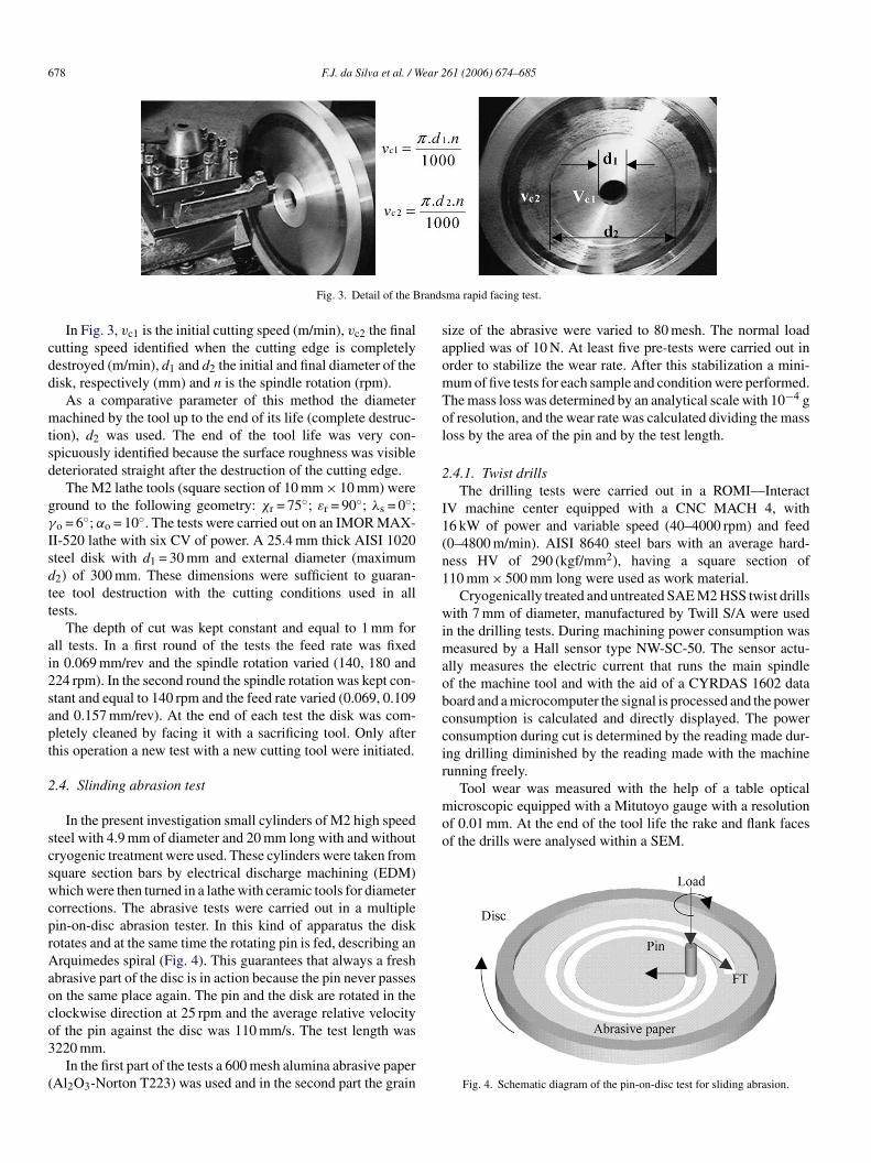
678 F.J. da Silva et al. / Wear 261 (2006) 674–685
rands
cdd
mtsd
gγ
Isdtt
ai2sapt
2
scswcprAaoco3
(
saomTol
2
I1(n1
wimaobccir
Tool wear was measured with the help of a table opticalmicroscopic equipped with a Mitutoyo gauge with a resolutionof 0.01 mm. At the end of the tool life the rake and flank facesof the drills were analysed within a SEM.
Fig. 3. Detail of the B
In Fig. 3, vc1 is the initial cutting speed (m/min), vc2 the finalutting speed identified when the cutting edge is completelyestroyed (m/min), d1 and d2 the initial and final diameter of theisk, respectively (mm) and n is the spindle rotation (rpm).
As a comparative parameter of this method the diameterachined by the tool up to the end of its life (complete destruc-
ion), d2 was used. The end of the tool life was very con-picuously identified because the surface roughness was visibleeteriorated straight after the destruction of the cutting edge.
The M2 lathe tools (square section of 10 mm × 10 mm) wereround to the following geometry: χr = 75◦; εr = 90◦; λs = 0◦;o = 6◦; αo = 10◦. The tests were carried out on an IMOR MAX-
I-520 lathe with six CV of power. A 25.4 mm thick AISI 1020teel disk with d1 = 30 mm and external diameter (maximum2) of 300 mm. These dimensions were sufficient to guaran-ee tool destruction with the cutting conditions used in allests.
The depth of cut was kept constant and equal to 1 mm forll tests. In a first round of the tests the feed rate was fixedn 0.069 mm/rev and the spindle rotation varied (140, 180 and24 rpm). In the second round the spindle rotation was kept con-tant and equal to 140 rpm and the feed rate varied (0.069, 0.109nd 0.157 mm/rev). At the end of each test the disk was com-letely cleaned by facing it with a sacrificing tool. Only afterhis operation a new test with a new cutting tool were initiated.
.4. Slinding abrasion test
In the present investigation small cylinders of M2 high speedteel with 4.9 mm of diameter and 20 mm long with and withoutryogenic treatment were used. These cylinders were taken fromquare section bars by electrical discharge machining (EDM)hich were then turned in a lathe with ceramic tools for diameter
orrections. The abrasive tests were carried out in a multiplein-on-disc abrasion tester. In this kind of apparatus the diskotates and at the same time the rotating pin is fed, describing anrquimedes spiral (Fig. 4). This guarantees that always a fresh
brasive part of the disc is in action because the pin never passesn the same place again. The pin and the disk are rotated in thelockwise direction at 25 rpm and the average relative velocity
f the pin against the disc was 110 mm/s. The test length was220 mm.In the first part of the tests a 600 mesh alumina abrasive paperAl2O3-Norton T223) was used and in the second part the grain
ma rapid facing test.
ize of the abrasive were varied to 80 mesh. The normal loadpplied was of 10 N. At least five pre-tests were carried out inrder to stabilize the wear rate. After this stabilization a mini-um of five tests for each sample and condition were performed.he mass loss was determined by an analytical scale with 10−4 gf resolution, and the wear rate was calculated dividing the massoss by the area of the pin and by the test length.
.4.1. Twist drillsThe drilling tests were carried out in a ROMI—Interact
V machine center equipped with a CNC MACH 4, with6 kW of power and variable speed (40–4000 rpm) and feed0–4800 m/min). AISI 8640 steel bars with an average hard-ess HV of 290 (kgf/mm2), having a square section of10 mm × 500 mm long were used as work material.
Cryogenically treated and untreated SAE M2 HSS twist drillsith 7 mm of diameter, manufactured by Twill S/A were used
n the drilling tests. During machining power consumption waseasured by a Hall sensor type NW-SC-50. The sensor actu-
lly measures the electric current that runs the main spindlef the machine tool and with the aid of a CYRDAS 1602 dataoard and a microcomputer the signal is processed and the poweronsumption is calculated and directly displayed. The poweronsumption during cut is determined by the reading made dur-ng drilling diminished by the reading made with the machineunning freely.
Fig. 4. Schematic diagram of the pin-on-disc test for sliding abrasion.

F.J. da Silva et al. / Wear 2
at
frhw
rAn
womVwmws
2
pmuMudbg
tio
1sowgwacNtfl
bwdat
ocpo
Tj
3
3
3
ruu
Fig. 5. Direction of application of the cutting fluid during drilling.
An emulsion of mineral oil at 5% of concentration was useds cutting fluid applied at a rate of 5 l/min according to the illus-ration shown in Fig. 5.
The cutting speeds used were 30, 35 and 40 m/min and theeed rate was constant at 0.11 mm/rev. A 3L/D (length of theole/diameter of the twist drill) rate was always used where theole length was then of 22.5 mm. The twist drills were groundith the following geometry: χr = 67.5◦; εr = 112.5◦; χ′
r = 0◦.The end of tool life criterion was the catastrophic failure,
ecommended by NORDTEST NT MECHE 038 [25] standard.ccording to this standard the tool life is determined by theumber of holes machined until immediately before tool failure.
The maximum and medium flank wear VBB max and VBBere frequently measured in order to have continuous controlf the behaviour of the wear development. This allowed to deter-ine the tool life under different criteria, e.g. VBB = 0.3 mm andBB max = 0.7 mm. The frequency of tool wear measurementas determined by the severity of the test. After eight holesachined the tool wear was measured when the cutting speedas 30 m/min and after four holes machined when the cutting
peed was 35 and 40 m/min.
.5. Shop floor tests
The shop floor tests were carried out in a car manufacturerlant. Special shaper milling cutter was used in these experi-ents. Both cryogenically treated and untreated tools were used
nder industrial cutting conditions. The cutters were also SAE2 HSS, this time TiN coated. They have two teeth and were
sed in a HURTH ZK7 machine tool that manufactures theented ring that engages the first and second speed in the gearox. During machining two shaper milling cutters are used toenerate the right and the left surface of the top tip of the teeth of
0
te
Fig. 6. View of the top of the teeth illustrating the surfaces ge
61 (2006) 674–685 679
he dented ring shown in Fig. 6. In this operation a straight lines produced at the mid top of each tooth which has the functionf facilitating engagement of the gears.
The dented ring is made of 19MnCr5G according to DIN7006 standard. The right and the left milling cutters operateimultaneously at different tooth in such a way that at the endf the cycle all the teeth are shaped. Tool wear was monitoredith the help of an optical microscope. The roughness of theenerated surface was measured by a PERTHEN-58p meter,ith a cut-off of 0.25 mm. At the end of tool lives the tools were
nalysed within a SEM. All the cuts were performed dry with autting speed of 89 m/min and a feed velocity of 1200 mm/min.ew and resharpened tools were tested. It is worth to mention
hat after resharpement the tools lose the coating at their mainank face.
The tool life was considered ended after 200 workpieces hadeen machined with the new tools and after 150 workpiecesith the resharpened tools. This end of tool life criteria wasetermined based on shop floor experience. Average flank wearnd the surface roughness were monitored at the beginning andowards the end of the tool lives.
In a second round a different end of tool life criterion basedn the observation of burr was adopted. This is an importantriterion since the workpieces are not submitted to a deburringrocess after machining and they would compromise the qualityf the dented rings.
Fig. 7 shows on the B detail the usual location of the burr.he inspection was done visually and in order to minimise sub-
ectivity errors only one person took charge of these tests.
. Results and discussion
.1. Laboratory tests (lathe tools)
.1.1. Microstrutural analysisThe X-ray difractometer results showed a difference in
etained austenite between the cryogenically treated andntreated tool samples. The untreated tool sample showed a vol-me of approximately 25% of retained austenite against nearly
% for the cryogenically treated tool sample.Table 3 shows the hardness of these samples. They are prac-ically the same; therefore the cryogenic treatment had no influ-nce on this property of the tools.
nerated by the right and the left shaper milling cutters.

680 F.J. da Silva et al. / Wear 261 (2006) 674–685
fsfdt
dwattr
3
trt
liut
TE
T
ABC
t0ttt
Fig. 7. Burr observed on a workpiece at the end of the tool life.
Microhardness results also did not show conspicuous dif-erence between the treated and untreated tools. The treatedamples had a mean value of 820 HV0.1 against 819 HV0.1or the untreated tools. Barron [10] also did not find significantifference between the cryogenically treated and untreated M2ools.
According to Collins [26] the precipitation of fine carbidesuring the cryogenic treatment cycle causes an increase in theear resistance and in the tool toughness, but only a small, if
ny, in the tool hardness. Actually he observed that initiallyhe hardness falls sharply at the cryogenic cycle and when theool is heated to the room temperature the hardness is totallyecovered.
.1.2. Brandsma (1936) rapid facing testsFig. 8 shows the results of the rapid facing tests. It is noticed
hat increasing both the rotate speed and the feed rate usuallyeduce the tool lives regardless the heat treatment submitted byhe tool.
The cryogenically treated tools always presented longer tool
ives when the spindle speed was varied. The results indicatedncreases of 12.5%, 44.0% and 21.0%, respectively, for testsnder 140, 180 and 224 rpm. When the feed rate was variedhe treated tools also presented better performance under theable 3ffect of the cryogenic treatment on the tool hardness
reated tools HRc Untreated tools HRc
66 D 6665 E 6566 F 66
gt
mcpshttmca
Fig. 8. Rapid facing test results.
wo smallest feed rates and only with the highest feed rate of.157 mm/rev the untreated tool presented a marginal betterool life than the treated tools (diameter of failure of 94 mm forhe untreated tool against 91 mm for the cryogenically treatedool).
These results suggest that the cryogenically treated tools areenerally better than the untreated tools but the cutting condi-ions have great influence on their performances.
The transformation of almost all retained austenite intoartensite, a harder structure, and precipitation of fine and hard
arbides as seen in the literature, are surely responsible for theseositive results of the cryogenically treated tools. This usualuperior performance can only be beaten when the relativelyigh percentage of the soft retained austenite of the untreatedools transforms into hard martensite during the severe action of
he cutting operation giving them a good wear resistance. Thisight explain the better performance of the untreated tool whenompared to the performance of the cryogenically treated toolt the highest feed rate of 0.157 mm/rev.

F.J. da Silva et al. / Wear 2
Fp
3
iuip1
fsoft
aaudgcar
ow
Haoobtsrs
pdp
smiowifia
tttiariue
ig. 9. Wear rate of the pin-on-disc for sliding abrasion tests (Al2O3 abrasiveaper).
.1.3. Sliding abrasion testFig. 9 presents the average wear rate obtained after slid-
ng abrasion wear testing using the cryogenically treated andntreated samples with 600 and 80 mesh abrasive papers. Withncreasing the abrasive grain size the wear rate increases pro-ortionally as expected since the abrasive diameter change from5 �m (600 mesh) to 180 �m (80 mesh).
Statistical analysis of the variance for the tests with 600 meshor both cryogenically treated and untreated samples did nothow significant difference of the average wear rates with 95%f reliability. However, for the 80 mesh the average wear rateor the cryogenically treated sample was slightly smaller (3.3%)han the untreated sample.
The transformation of the approximately 25% of the retainedustenite into martensite after cryogenic treatment did not lead tosignificant alteration of the abrasive wear rate at the conditionssed in the pin-on-disc tests. Literature results [27] showed that,epending on the test parameters such as normal load, average
rain size and type of the abrasive, quantity and shape of thearbides, among others, the increasing of the amount of retainedustenite can lead to an increase or to a decrease in the wearate of ferrous alloys. This behaviour is associated to the abilityhaim
Fig. 10. Typical worn surface of (a) treated and (b) untreated sampl
61 (2006) 674–685 681
f the austenite to harden during plastic deformation either byorkhardening or by martensite transformation.The abrasive wear tests carried out by Barron [14] on the M2
SS cryogenically treated at −196 ◦C (cooling rate of 3 ◦C/mimnd maintained for 24 h) had an increase on the wear resistancef 20% when compared to untreated samples. Discrepanciesf Barron’s results with those of the present investigation maye credited to different parameter conditions used. At Barron’sests the normal load was 430 N, feed velocity of 0.48 m/s andample diameter of 12.7 mm against 10 N, 110 m/s and 4.9 mm,espectively, at the present investigation. This is really a test veryensible to the test conditions.
The wear resistance as a function of the fine carbides that hasossibly precipitated during cryogenic treatment is also veryependent on the test conditions chiefly on the feed velocity andercentage of precipitation of carbides [28].
The worn surfaces of the cryogenically treated and untreatedamples are shown in Fig. 10. It is observed that the wearechanisms were microplowing and microcutting. No signif-
cant difference can be noticed regarding to the proportionf these two mechanisms, suggesting, therefore, an effectiveorkhardening process or even transformation of the austenite
nto martensite during test of the untreated sample, as veri-ed by Zum Gahr [27] in several ferrous materials and SiCbrasive.
The hardness and the abrasive tests did not show resultshat could justify the better performance of the cryogenicallyreated HSS tools in machinability tests. During machininghe phenomena are very specifics, with very high chip–toolnterface temperatures, very high tension on the tool surfacesnd great interaction between the tool and the work mate-ial and compared to sliding abrasive tests the wear occursn a smaller scale. At the cutting conditions and tools (HSS)sed in the present investigation the main wear mechanismsxpected is abrasion and attrition [29]. The results obtained
ere showed that probably the transformation of the retainedustenite into martensite and precipitation of fine carbides dur-ng cryogenic treatment is beneficial in the presence of such wearechanisms.
es, after pin-on-disc tests with 80 mesh Al2O3 abrasive paper.

682 F.J. da Silva et al. / Wear 261 (2006) 674–685
F
3
bcrii
rtolpVcpct7u
Table 4Number of holes for end of tool life criteria VBB = 0.3 mm, VBB max = 0.7 mmand catastrophic failure
30 m/min 35 m/min 40 m/min
Untreated Treated Untreated Treated Untreated Treated
VBB 0.30 mm 120 a a a 12 26VBB max
0.70 mm
a 208 a 88 a a
Catastrophicfailure
149 368 55 91 14 62
a Criterion not reached.
FV
duc
cally treated and untreated tools were generally very similar and
Fc
ig. 11. Twist drill lives given in numbers of holes until the catastrophic failure.
.2. Laboratory tests (twist dills)
Fig. 11 summarizes the results of tool life tests given in num-ers of holes machined. It can be observed that increasing theutting speed the lives of the twist drills reduces considerablyegardless the heat treatment condition of the tool material. Thiss due to the increase of the chip tool interface temperature withncreasing cutting speed.
The lives of the cryogenically treated tools were always supe-ior to those given by the untreated tools. In percentage termshe differences were 147%, 65%, 343% for the cutting speedsf 30, 35 and 40 m/min, respectively. When other end of toolife criteria is used, according to Table 4, different results areroduced. Considering the end of tool life criteria of VBB,BB max and catastrophic failure simultaneously lives of the
ryogenically treated and untreated tools is modified to valuesresented in the curve of Fig. 12. Although with lower per-entages the cryogenically treated tools performed far better
han the untreated tools. The percentages are now modified to3%, 60%, 117%, respectively, depending on the cutting speedsed.osa
ig. 13. Worn areas of the flank face of the twist drills used at vc = 40 m/min andryogenic treatment (after 14 holes).
ig. 12. Number of holes machined for simultaneous end of tool life criteria ofBB = 0.3 mm VBB max = 0.7 mm and catastrophic failure.
Fig. 13 shows the worn areas of the flank face of the twistrills used with the cutting speed of 40 m/min. The wear of thentreated tool, after 14 holes machined is clearly bigger than theryogenically treated tool, after 62 holes machined.
The power consumption when drilling with both cryogeni-
nly occasionally the untreated tools showed lower power con-umption than the treated tools during drilling. This could ben indication that the microstructure changes (transformation of
f = 0.11 mm/rev: (a) with cryogenic treatment (after 62 holes) and (b) without

ear 261 (2006) 674–685 683
tcce
daatputt
3
t2ttt
hb
1f
c
F.J. da Silva et al. / W
he retained austenite into martensite and precipitation of finearbides) do not cause modification on the chip formation pro-ess to the point of modifying the cutting forces, but they cannhance wear resistance as shown previously.
However, this analysis needs further subsidies because whenrilling four different work materials with cryogenically treatednd untreated T1 twist drills at various cutting conditions, Cohennd Kamody [30] found lower power consumption for the treatedools for three work materials (33%, 8.5% and 4.7%) when com-ared to the untreated tools and only for one work material thentreated tool showed smaller (6%) power consumption than itsreated counterpartner. Microstructure changes may have con-ributed to Cohen and Kamody’s results.
.3. Shop floor tests (special shaper milling cutter)
Fig. 14 presents the values of the average flank wear ofhe right and left milling cutters (new tools) after machining00 workpieces for the teeth nos. 1 and 2. The cryogenicallyreated tools present higher average flank wear than the untreatedools. This fact was also observed when using resharpened
ools.Although the wear of the cryogenically treated tools wereigher than the untreated ones the surface roughness generatedy the two tools were very similar (Ra varying from 0.99 to
mdut
Fig. 15. Right milling cutters—ne
Fig. 14. Flank wear of milling cutters after machining 200 workpieces.
.63 �m for the surface generated by the treated new tools androm 0.98 to 1.41 �m for the new untreated tools).
Fig. 15 shows the cutting edges of the right hand side millingutters of the cryogenically treated and untreated new tools afterachining 200 workpieces. It is clearly seen the higher wear
eveloped on the cryogenically treated tools compared to thentreated ones. It is noticed that the coatings at the flank face ofhe tools were worn out.
w after 200 parts produced.

684 F.J. da Silva et al. / Wear 2
Ft
uttcwc
apgTito
wtasfasf
owt
cntcmtttcic
dio
4
f
1
2
3
4
5
6
7
A
fffs
References
ig. 16. Average of parts produced by the cryogenically treated and untreatedools when using the appearance of burrs as the end of tool life criterion.
Fig. 16 shows the production of the cryogenically treated andntreated tools when using the formation of burrs as the end ofool life criterion. In these tests the tools were resharpened fourimes, resulting in a total of 380 parts produced by the cryogeni-ally treated tools and 491 parts produced by the untreated toolsith an average of 95 and 123 parts produced per life by the
ryogenically treated and untreated tools, respectively.It was seen that the cryogenic treatment in such a way had
negative effect on the performance of the tools when com-ared to the untreated ones. According to Paulin [2] the cryo-enic treatment can be applied to coated tools satisfactorily.he same is cited by Cohen and Kamody [30] who found 42%
ncrease in tool life of cryogenically treated TiCN coated M4ools when comparing to untreated coated tools in a broachingperation.
They did not say, however, whether the cryogenic treatmentas applied to the tool before or after the coating operation of
he tools. If the treatment was applied after the coating operationcritical tension state can appear between the coating and the
ubstrate causing adherence problems. These materials have dif-erent expansion coefficient, being 12 × 10−6 K−1 for the HSSnd 9.4 × 10⁻⁶ K−1 for the TiN. This can create triaxial tensiontate at the coating and substrate interface that can promote theragmentation and rapid wear of the coating layer.
The appearance of burrs is directly related to the developmentf the wear and the results shown here reflects the relative lowear resistance of the cryogenically treated tools compared to
he untreated counterpartners as seen.The results presented by this investigation reveal that the
ryogenic treatment is a technique that demands further studiesot only on uncoated tools but also on coated tools. It is knownhat there is transformation of austenite into martensite and pre-ipitation of fine carbides that are well distributed into the wholeatrix of the cryogenically treated steels [13,16]. The result of
he cryogenic treatment and consequently the efficiency of thereated tool is very dependent of the thermal cycle, includinghe cryogenic temperatures involved. The optimisation of this
ycle for each individual application must therefore be huntedn order to have success of the technique. The particular case ofoated tools demands detailed understanding of the phenomena61 (2006) 674–685
eveloped during the thermal treatment at the coating–substratenterface that could help to explain the process of deteriorationf this kind of tools.
. Conclusions
Based on the results obtained in the present investigation theollowing conclusions can be drawn:
. The hardness and the microhardness of the M2 HSS sampleswere not significantly affected by the cryogenic treatment.
. The samples cryogenically treated showed a fraction veryclose to 0% of retained austenite. This means that practicallythe 25% in volume of the retained austenite observed in theuntreated sample were transformed into martensite by thecryogenic treatment.
. A superior performance of the cryogenically treated toolscompared to the untreated ones was observed in theBrandsma rapid facing test. This difference reached 44% insome cutting conditions.
. The difference on the percentage of retained austenite of thecryogenically treated and untreated samples did not alter theabrasive wear rate at the conditions used here for the slid-ing abrasion tests. This is possibly due to the ability of theaustenite of the untreated samples to harden during plasticdeformation either by workhardening or by its transforma-tion into martensite. These phenomena may compensate thegain obtained by precipitation of fine carbides in the cryo-genically treated samples.
. The cryogenic treatment increased the performance of theM2 HSS twist drills. The gain observed during drilling steelsadopting catastrophic failure as the end of tool life criterionvaried from 65% to 343% depending on the cutting condi-tions used.
. Shop floor tests with cryogenically treated coated HSSmilling cutters presented worse performance than untreatedtools when shaping the top surface of the teeth of gear rings.
. Overall the cryogenic treatment had favourable influences onthe performance of the tools tested. This means that depend-ing on the application the cryogenic treatment may be a goodalternative for having productivity enhancement. Optimiza-tion of the parameters involved in the whole thermal cyclemust, however, precede the application.
cknowledgements
The authors would like to thank Cryo Quality Ltd. Companyor carrying out the cryogenic treatment in the samples; CAPESor the scholarship offered to one of the authors; FAPEMIGor the financial support and Fiat-GM PowerTrain for technicalupport.
[1] A.R. Machado, M.B. da Silva, Usinagem dos Metais (Metal Machining),3rd ed., Editora da Universidade Federal de Uberlandia, MG, Brazil, 2003,p. 275 (in Portuguese).

ear 2
[
[
[
[
[
[[
[
[
[
[
[
[
[
[
[
[
[
[
F.J. da Silva et al. / W
[2] P. Paulin, Frozen gears, Gear Technol. (1993) 26–28.[3] E.A. Smolnikov, G.A. Kossovich, Cold Treatment of Cutting Tools (trans-
lated from Metallovedenie i Termicheskaya Obrabotka Metallov), no. 10,1980, pp. 5–7.
[4] L.B. Tseitlin, V.D. Kolensnichenko, T.V. Karnaushenko, V.V. Umanets,E.S. Zhmud, Tool Life of High Speed Steel Cutters After Cold Treatment(translated from Metallovedenie i Termicheskaya Obrabotka Metallov), no.10, 1980, pp. 7–9.
[5] E.S. Zhmud, Improved Tool Life After Shock Cooling (translated fromMetallovedenie i Termicheskaya Obrabotka Metallov), no.10, 1980, pp.3–5.
[6] A.P. Gulyaev, Improved methods of heat treating high speed steels toimprove the cutting properties, Metallurgy (12) (1937) 65.
[7] R.B. Reasbeck, Improved tool life by the cryotough treatment, Metallurgia(1989) 178–179.
[8] D.S. Zamborsky, Control of distortion in tools steels, in: The Heat TreatingSource Book, ASM, 1986, pp. 73–79.
[9] J.M. Heberling, Tool steel tutorial, Heat Treating (1992) 22–30.10] F.R. Barron, Yes—Cryogenic Treatments Can Save You Money! Here’s
Why, Tapi 57 (5) (1974) 35–40.11] A.N. Popandopulo, L.T. Zhukova, Transformations in High Speed Steels
During Cold Treatment (translated from Metallovedenie i TermicheskayaObrabotka Metallov), no. 10, 1980, pp. 9–11.
12] J.Y. Huang, Y.T. Zhu, X.Z. Liao, I.J. Beyerlein, M.A. Bourke, T.E. Mitchell,Microstructure of cryogenic treated M2 tool steel, Mater. Sci. Eng. A399(2003) 241–244.
13] Alexandru, G. Ailincai, C. Baciu, Influence de traitements thermiques abasse tempeature sur la duree de vie des aciers a outils a coupe reapide tres,Memoires et etudes scientifiques revue de Metallurgie (1990) 283–388 (inFrench).
14] R.F. Barron, Cryogenic treatment of metals to improve wear resistance,Cryogenics (1982) 409–413.
15] M.A. Moore, A review of two-boby abrasive wear, Wear 27 (1974) 1–17.16] D. Yun, L. Xiaoping, X. Hongshen, Deep cryogenic treatment of high-speed
steel and its mechanism, Heat Treat. Met. (1998) 55–59.
[
[
61 (2006) 674–685 685
17] A. Molinari, M. Pellizzari, S. Gialanella, G. Straffelini, K.H. Stiasny, Effectof deep cryogenic treatment on the mechanical properties of tool steels, J.Mater. Process. Technol. 118 (2001) 350–355.
18] D. Mohan Lal, S. Renganarayanan, A. Kalanidhi, Cryogenic treatmentto augment wear resistance of tool and die steels, Cryogenics 41 (2001)149–155.
19] M.C. Huang, C.H. Gao, L.G. Huang, Study on cryogenic phase change andwear characteristic of high speed steel, Acta Metall. Sin. (English Lett.) 16(6) (2003) 524–530.
20] V. Leskovsek, B. Ule, Influence of deep cryogenic treatment on microstruc-ture, mechanical properties and dimensional changes of vacuum heat-treated high-speed steel, Heat Treat. Met. (UK) 29 (3) (2002) 72–76.
21] R. Mahmudi, H.M. Ghasemi, H.R. Faradji, Effect of cryogenic treatmentson the mechanical properties and wear behaviour of high-speed steel M2,Heat Treat. Met. (UK) 27 (3) (2000) 69–72.
22] X. Lin, Y. Dong, Y. Wang, Study on cryogenic treatment technology andmechanism of high speed steels, Trans. Met. Heat Treat. (China) 19 (2)(1998) 21–25.
23] ASMT E 975-03, Standard practice for X-ray determination of retainedaustenite in steel with near random crystallographic orientation, Book ofStandards, vol. 03.01, ASTM International.
24] D. Ferraresi, Fundamentos da Usinagem dos Metais (Fundaments of MetalCutting), Editora Edgard Blucher Ltd., 1977, p. 751 (in Portuguese).
25] NODTEST NT MECH 038, Cutting fluids for drilling: evaluation by drilllife test, Nordtest Method, Proj. 1242-95/2, 1997, ISSN 0283-7196.
26] D.N. Collins, Deep cryogenic treatment of tool steels: a review, Heat Treat.Met. (2) (1996) 40–42.
27] K.H. Zum Gahr, Microstructure and Wear of Materials, Elsevier SciencePublishers Inc., Amsterdam, 1987, p. 590.
28] J.D. Kamody, Using deep cryogenics to advantage, Adv. Mater. Process.
10 (1998) 215–218.29] P. Wright, E.M. Trent, Metal Cutting, 4th ed., Heinemann Ltd., Butter-worths, 2001, p. 273. ISBN 0-7506-1068-9.
30] P. Cohen, D. Kamody, Cryogenics goes deeper, Cutting Tool Eng. l50 (7)(1998) 46–50.