performance of a research prototype humanoid robot bonten...
TRANSCRIPT

Performance of a Research Prototype Humanoid Robot Bonten-Maru II to Attain Human-Like Motions
HANAFIAH YUSSOF1, MITSUHIRO YAMANO2, YASUO NASU2, MASAHIRO OHKA1
1Graduate School of Information Science, Nagoya University Furo-cho Chikusa-ku Nagoya Aichi 466-0815
2Department of Mechanical Systems Engineering, Faculty of Engineering, Yamagata University Jonan 4-3-16 Yonezawa Yamagata 992-8510
JAPAN [email protected] http://ns1.ohka.cs.is.nagoya-u.ac.jp/ohka_lab2/index_eng.html
Abstract: - This report presents development of basic human-like motions using a research prototype 21-dof humanoid robot called Bonten-Maru II. The aim is to create suitable motion trajectories towards application of humanoid robots in real environments. Kinematical analysis of 3-dof arm and 6-dof leg were presented to generate trajectory in the robot’s arms and legs. To realize human-like motions, we proposed navigation method based on contact interaction for humanoid robot to recognize its surrounding by grasping object surface and then correcting its locomotion direction. We also proposed methods to avoid high and low obstacles. Finally, we present crawling motions which can be applied during operation in emergency sites. The experimental results utilizing Bonten-Maru II revealed good performance of the robot when performing human-like motions in the proposed navigation method, obstacle avoidance, and crawling motions. Key-Words: - Humanoid robot, human-like motions, trajectory generation, kinematics, contact-based navigation, obstacle avoidance, crawling motion 1 Introduction Research in humanoid robotics is currently shifting from locomotion and stability issues to interaction between humans and robots. These motivations are derived from the intention to develop intelligent and human-friendly machine to replace human in dangerous sites, to assist the elderly and the disabled, to entertain children and to communicate in a natural language. This will provide humans with more safety, freedom and time.
Humanoid robots are the type of robot that practically suitable to coexist with human in built-for-human environment because of its anthropomorphism, human friendly design and locomotion ability [1][2]. Humanoid robot is different compare to other types of robots because the physical structure is designed to mimic as much as human’s physical structure. Humanoid’s shape shares many basic physical characteristics with actual humans, and for this reason, they are expected to coexist and collaborate with humans in environments where humans work and live. They may also be substituted for humans in hazardous environments or at disaster sites. These demands make it imperative for humanoid robots to attain many sophisticated motions such as walking, climbing stairs, avoiding obstacles, crawling, etc.
It is apparent that to work with humans, humanoid robots must be able to recognize and perform human-like motion. In the past decade, we have seen enthusiastic efforts by robot researchers to develop anthropomorphic humanoid robots, ones that can think intelligently and mimic human action [3-6]. The most successful introduction of humanoid robots nowadays probably goes to Asimo, Qrio and HRP-2. In our research laboratory, we have developed a research prototype 21-dof humanoid robot called Bonten-Maru II. Bonten-Maru II is a low-cost research prototype humanoid robot and is one of few research prototype humanoid robots in the world which can be utilized in various aspects of studies. It is our goal that the works done in the Bonten-Maru II projects will give some impact on further research in the humanoid robotics.
In this report, we present experimental results of humanoid robot Bonten-Maru II to attain human-like motion with the aim to operate in built-for-human environment. Firstly, we present method to solve kinematics problems in trajectory generation of the robot arms and legs. Second we introduced navigation strategy applying contact interaction where humanoid robot touch and grasp object using its arms and correcting its locomotion directions. Finally we present motions of avoiding low and high obstacles, and crawling.
WSEAS TRANSACTIONS on SYSTEMS and CONTROLManuscript received June 27, 2007; revised Sep. 24, 2007
Hanafiah Yussof, Mitsuhiro Yamano,Yasuo Nasu, Masahiro Ohka
ISSN: 1991-8763 458 Issue 9, Volume 2, September 2007
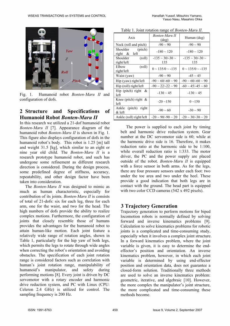
Fig. 1. Humanoid robot Bonten-Maru II and configuration of dofs. 2 Structure and Specifications of Humanoid Robot Bonten-Maru II In this research we utilized a 21-dof humanoid robot Bonten-Maru II [7]. Appearance diagram of the humanoid robot Bonten-Maru II is shown in Fig. 1. This figure also displays configuration of dofs in the humanoid robot’s body. This robot is 1.25 [m] tall and weight 31.5 [kg], which similar to an eight or nine year old child. The Bonten-Maru II is a research prototype humanoid robot, and such has undergone some refinement as different research direction is considered. During the design process, some predefined degree of stiffness, accuracy, repeatability, and other design factor have been taken into consideration.
The Bonten-Maru II was designed to mimic as much as human characteristic, especially for contribution of its joints. Bonten-Maru II is consists of total of 21-dofs: six for each leg, three for each arm, one for the waist, and two for the head. The high numbers of dofs provide the ability to realize complex motions. Furthermore, the configuration of joints that closely resemble those of humans provides the advantages for the humanoid robot to attain human-like motion. Each joint feature a relatively wide range of rotation angles, shown in Table 1, particularly for the hip yaw of both legs, which permits the legs to rotate through wide angles when correcting the robot’s orientation and avoiding obstacles. The specification of each joint rotation range is considered factors such as correlation with human’s joint rotation range, manipulability of humanoid’s manipulator, and safety during performing motions [8]. Every joint is driven by DC servomotor with a rotary encoder and harmonic drive reduction system, and PC with Linux (CPU: Celeron 2.4 GHz) is utilized for control. The sampling frequency is 200 Hz.
The power is supplied to each joint by timing belt and harmonic drive reduction system. Gear number at the DC servomotor side is 60; while at the harmonic drive side is 16. Therefore, it makes reduction ratio at the harmonic side to be 1:100, while overall reduction ratio is 1:333. The motor driver, the PC and the power supply are placed outside of the robot. Bonten-Maru II is equipped with a force sensor in both arms. As for the legs, there are four pressure sensors under each foot: two under the toe area and two under the heel. These provide a good indication that both legs are in contact with the ground. The head part is equipped with two color CCD cameras (542 x 492 pixels).
3 Trajectory Generation Trajectory generation to perform motions for biped locomotion robots is normally defined by solving forward and inverse kinematics problems [9]. Calculation to solve kinematics problems for robotic joints is a complicated and time-consuming study, especially when it involves a complex joint structure. In a forward kinematics problem, where the joint variable is given, it is easy to determine the end-effector’s position and orientation. An inverse kinematics problem, however, in which each joint variable is determined by using end-effector position and orientation data, does not guarantee a closed-form solution. Traditionally three methods are used to solve an inverse kinematics problem: geometric, iterative, and algebraic [10]. However, the more complex the manipulator’s joint structure, the more complicated and time-consuming these methods become.
ZZ
YY XX
YYaaww
PPiittcchh
RRoollll
Table 1. Joint rotation range of Bonten-Maru II.
Axis Bonten-Maru II (deg) Human (deg)
Neck (roll and pitch) -90 ~ 90 -90 ~ 90 Shoulder (pitch) right & left -180 ~ 120 -180 ~ 120
Shoulder (roll) right/left
-135 ~ 30/-30 ~ 135
-135 ~ 30/-30 ~ 135
Elbow (roll) right/left 0 ~ 135/0 ~ -135 0 ~ 135/0 ~ -135
Waist (yaw) -90 ~ 90 -45 ~ 45 Hip (yaw) right/left -90 ~ 60/-60 ~ 90 -90 ~ 60/-60 ~ 90Hip (roll) right/left -90 ~ 22/-22 ~ 90 -60 ~ 45/-45 ~ 60Hip (pitch) right & left -130 ~ 45 -130 ~ 45
Knee (pitch) right & left -20 ~150 0 ~150
Ankle (pitch) right & left -90 ~ 60 -30 ~ 90
Ankle (roll) right/left -20 ~ 90/-90 ~ 20 -20 ~ 30/-30 ~ 20
WSEAS TRANSACTIONS on SYSTEMS and CONTROL Hanafiah Yussof, Mitsuhiro Yamano,Yasuo Nasu, Masahiro Ohka
ISSN: 1991-8763 459 Issue 9, Volume 2, September 2007

In this paper, we propose and implement a simplified approach to solving inverse kinematics problems by classifying the robot’s joints into several groups of joint coordinate frames at the robot’s manipulator [11]. To describe translation and rotational relationship between adjacent joint links, we employ a matrix method proposed by Denavit-Hartenberg [12], which systematically establishes a coordinate system for each link of an articulated chain in the robot body.
3.1 Kinematical Solutions for 3-dof Arm The humanoid robot Bonten-Maru II has three dofs on each arm: two dofs (pitch and roll) at the shoulder joint and one dof (roll) at the elbow joint. Figure 2 shows the arm structure and configuration of joints and links. The coordinate orientation follows the right-hand law, and a reference coordinate is fixed at the intersection point of two joints at the shoulder. Figure 3 displays a model of the robot arm describing the configurations and orientation of each joint coordinates. To avoid confusion, only the x and z-axes appear in the figure. The arm’s structure is divided into five sets of joint-coordinates frames as listed below:
∑0 : Reference coordinate. ∑1 : Shoulder joint pitch coordinate. ∑2 : Shoulder joint roll coordinate. ∑3 : Elbow joint roll coordinate. ∑h : End-effector coordinate.
Consequently, corresponding link parameters of the arm can be defined as shown in Table 2. From the Denavit-Hartenberg convention mentioned above, definitions of the homogeneous transform matrix of the link parameters can be described as follows:
0h T= Rot(z,θ)Trans(0,0,d)Trans(l,0,0)Rot(x,α). (1)
Here, variable factor θi is the joint angle between the xi-1 and the xi axes measured about the zi axis; di is the distance from the xi-1 axis to the xi axis measured along the zi axis; αi is the angle between the zi axis to the zi-1 axis measured about the xi-1 axis, and li is the distance from the zi axis to the zi-1 axis measured along the xi-1 axis. Here, link length for the upper and lower arm is described as l1 and l2, respectively. The following is used to obtain the forward kinematics solution for the robot arm:
0h T= 0
1 T 12 T 2
3 T 3h T
⎥⎥⎥⎥
⎦
⎤
⎢⎢⎢⎢
⎣
⎡
+−−++−
=
1000clclcssccc
slsl0csclclscsscs
2322111231231
232212323
2322111231231
)(
)(
. (2)
Table 2. Link parameters of the robot arm. Link θiarm d α l
0 θ1arm-90º 0 90 º 0 1 θ2arm 0 -90 º 0 2 θ3arm 0 0 l1 3 0 0 0 l2
The end-effector’s orientation with respect to the
reference coordinate ( 0h R) is shown in (3), while the
position of the end-effector (0Ph) is shown in (4). The position of the end-effector in regard to global axes Px, Py and Pz can be define by (5). Here, si and ci are respective abbreviations of sinθi and cosθi, where (i=1,2,…,n) and n is equal to quantity of dof.
0h Rarm
⎥⎥⎥
⎦
⎤
⎢⎢⎢
⎣
⎡
−
−=
1231231
2323
1231231
ssccc0cscsscs
(3)
0Ph
⎥⎥⎥
⎦
⎤
⎢⎢⎢
⎣
⎡
+−++
=)(
)(
arm
232211
23221
232211
clclcslslclcls
(4)
⎪⎪⎭
⎪⎪⎬
⎫
+−=
+=
+=
)(
)(
arm
arm
arm
232211z
23221y
232211x
clclcP
slslPclclsP
(5)
oz
ox1z
1x
2z
2x
3x
hx
3z
hz
oz
ox1z
1x
2z
2x
3x
hx
3z
hz
Fig. 3. Configurations of joint coordinates at the robot arm.
Fig. 2. Arm structure of Bonten-Maru II.
WSEAS TRANSACTIONS on SYSTEMS and CONTROL Hanafiah Yussof, Mitsuhiro Yamano,Yasuo Nasu, Masahiro Ohka
ISSN: 1991-8763 460 Issue 9, Volume 2, September 2007

As understood from (3) and (4), a forward kinematics equation can be used to compute the Cartesian coordinates of the robot arm when the joint angles are known. However, in real-time applications it is more practical to provide the end-effector’s position and orientation data to the robot’s control system than to define each joint angle that involved complicated calculations. Therefore, inverse kinematics solutions are more favourable for generating the trajectory of the humanoid robot manipulator. To define joint angles θ1arm, θ2arm, θ3arm in an inverse kinematics problem, at first each position element in (5) is multiplied and added to each other according to (6), which can also be arranged as (7). Thus, θ3arm is defined in (8).
3212
22
12
z2
y2
x cll2llPPP ++=++ armarmarm (6)
Cll2
llPPPc
21
22
21
2z
2y
2x
3 =+−++
=)(armarmarm (7)
⎟⎠⎞⎜
⎝⎛ −±= CC1 2
3 ,atan2armθ (8)
Referring to the rotation direction of θ3arm, if
sinθ3arm is a positive value, it describes the inverse kinematics for the right arm, while if it is a negative value it described the left arm. Consequently, θ3arm is used to define θ2arm, as shown in (9) ~ (13), where newly polar coordinates are defined in (11). Consequently, θ1arm can be defined as in (14).
3223211 slkcllk −=+= , (9)
2122y2221xz skckpskckp −=+= , (10) ),(atan2 21 kk=φ (11)
( )yxz
yxz2
pp
rp
rp
,atan2
,atan2arm
=
⎟⎟⎠
⎞⎜⎜⎝
⎛=+θφ
(12)
( ) ( )21yxz2 kkpp ,atan2,atan2arm −=θ (13)
( )zx
xz
z
xz
x1
pppp
pp
,atan2
,atan2arm
=
⎟⎟⎠
⎞⎜⎜⎝
⎛=θ
(14)
3.2 Kinematical Solutions for 6-dof Leg Each of the legs has six dofs: three dofs (yaw, roll and pitch) at the hip joint, one dof (pitch) at the knee joint and two dofs (pitch and roll) at the ankle joint. In this research, we solve only inverse kinematics calculations for the robot leg. Figure 4 shows the structure and configuration of joints and links in the robot’s leg. A reference coordinate is taken at the
intersection point of the 3-dof hip joint. In solving calculations of inverse kinematics for the leg, just as for arm, the joint coordinates are divided into eight separate coordinate frames as listed bellow.
∑0 : Reference coordinate. ∑1 : Hip yaw coordinate. ∑2 : Hip roll coordinate. ∑3 : Hip pitch coordinate. ∑4 : Knee pitch coordinate. ∑5 : Ankle pitch coordinate. ∑6 : Ankle roll coordinate. ∑h : Foot bottom-center coordinate. Table 3. Link parameters of the leg.
Link θileg d α l 0 θ1leg+90º 0 0 0 1 θ2leg-90 º 0 90 º 0 2 θ3leg 0 90 º 0 3 θ4leg 0 0 l1 4 θ5leg 0 0 l2 5 θ6leg 0 -90 º 0 6 0 0 0 l3
ox
1, zzo
1x2z3z
3x4x
4z
5z
5x6z
6x
hxhz
hy
oy
ox
1, zzo
1x2z3z
3x4x
4z
5z
5x6z
6x
hxhz
hy
oy
Fig. 4. Leg structure of Bonten-Maru II.
Fig. 5. Configurations of joint coordinates at the robot leg.
WSEAS TRANSACTIONS on SYSTEMS and CONTROL Hanafiah Yussof, Mitsuhiro Yamano,Yasuo Nasu, Masahiro Ohka
ISSN: 1991-8763 461 Issue 9, Volume 2, September 2007

Figure 5 shows a model of the robot leg that indicates the configurations and orientation of each set of joint coordinates. Here, link length for the thigh is l1, while for the shin it is l2. The same convention applies for the arm link parameter mentioned earlier. Link parameters for the leg are defined in Table 3.
Referring to Fig. 5, the transformation matrix at the bottom of the foot ( 6
h T) is an independent link parameter because the coordinate direction is changeable. Here, to simplify the calculations, the ankle joint is positioned so that the bottom of the foot settles on the floor surface. The leg’s orientation is fixed from the reference coordinate so that the third row of the rotation matrix at the leg’s end becomes like (15).
[ ]Tz 100P =leg (15) Furthermore, the leg’s links are classified into
three groups to short-cut the calculations, where each group of links is calculated separately as follows: i) From link 0 to link 1 (Reference coordinate to
coordinate joint number 1). ii) From link 1 to link 4 (Coordinate joint number 2
to coordinate joint number 4). iii) From link 4 to link 6 (Coordinate joint number 5
to coordinate at the bottom of the foot). Basically, i) is to control leg rotation at the z-axis,
ii) is to define the leg position, while iii) is to decide the leg’s end-point orientation. A coordinate transformation matrix can be arranged as below.
0h T= 0
1 T 14 T 4
h T= ( 0h T)( 1
2 T 23 T 3
4 T)( 45 T 5
6 T 6h T) (16)
Here, the coordinate transformation matrices for 14 T
and 4h T can be defined as (17) and (18), respectively.
14 T= 1
2 T 23 T 3
4 T
⎥⎥⎥⎥
⎦
⎤
⎢⎢⎢⎢
⎣
⎡
−−−−−−
−−
=
1000cclssccc
sl0cscslcsscs
3212342342
313434
3212342342
(17)
4h T= 4
5 T 56 T 6
h T
⎥⎥⎥⎥
⎦
⎤
⎢⎢⎢⎢
⎣
⎡
−−−−
+−−
=
1000sl0cscslcsscs
ccllssccc
6366
65356565
653256565
(18)
The coordinate transformation matrix for 0
h T, which describes the leg’s end-point position and orientation, can be shown with the following equation.
0h T
⎥⎥⎥⎥
⎦
⎤
⎢⎢⎢⎢
⎣
⎡
=
1000prrrprrrprrr
z333231
y232221
x131211
(19)
From equation (15), the following conditions were satisfied.
10 3332312313 ===== rrrrr , (20) Hence, joint rotation angles θ1leg~θ6leg can be defined by applying the above conditions.
First, considering i), in order to provide rotation at the z-axis, only the hip joint needs to rotate in the yaw direction, specifically by defining θ1leg. As mentioned earlier, the bottom of the foot settles on the floor surface; therefore, the rotation matrix for the leg’s end-point measured from the reference coordinate can be defined by the following equation.
0h R ),(Rot leg1z θ=
⎥⎥⎥
⎦
⎤
⎢⎢⎢
⎣
⎡=
⎥⎥⎥
⎦
⎤
⎢⎢⎢
⎣
⎡ −=
10000
10000
2221
1211
11
11
rrrr
cssc
legleg
legleg
θθθθ
(21)
Here, θ1leg can be defined as below. ( )22211 rr ,atan2leg =θ (22)
Next, considering ii), from the obtained result of θ1leg, 0
h T is defined in (23).
0h T
⎥⎥⎥⎥⎥
⎦
⎤
⎢⎢⎢⎢⎢
⎣
⎡−−−
=
1000P100P0scP0cs
z
y11
x11
leg
leg
leg
(23)
Here, from constrain orientation of the leg’s end point, the position vector of joint 5 is defined as follows in (24), and its relative connection with the matrix is defined in (25). Next, equation (26) is defined relatively.
0P5= 04 T4P5 [ ]T3zyx lPPP −= leglegleg , (24)
5010
1541
4 PTPT ˆˆ −= (25)
⎥⎥⎥⎥
⎦
⎤
⎢⎢⎢⎢
⎣
⎡
−⎥⎥⎥⎥
⎦
⎤
⎢⎢⎢⎢
⎣
⎡−−
−
=
⎥⎥⎥⎥
⎦
⎤
⎢⎢⎢⎢
⎣
⎡
⎥⎥⎥⎥
⎦
⎤
⎢⎢⎢⎢
⎣
⎡
−−−−−−
−−
1lp
pp
1000010000sc00cs
100l
1000cclssccc
sl0cscslcsscs
3z
y
x
11
11
2
3212342342
313434
3212342342
(26)
Therefore, ( )( )( )⎥
⎥⎥
⎦
⎤
⎢⎢⎢
⎣
⎡
+−+−+
=
⎥⎥⎥⎥⎥
⎦
⎤
⎢⎢⎢⎢⎢
⎣
⎡
342312
34231
342312
z
y
x
clclcslclclcls
P
P
P
leg
leg
leg
ˆ
ˆ
ˆ
. (27)
WSEAS TRANSACTIONS on SYSTEMS and CONTROL Hanafiah Yussof, Mitsuhiro Yamano,Yasuo Nasu, Masahiro Ohka
ISSN: 1991-8763 462 Issue 9, Volume 2, September 2007

To define joint angles θ2leg, θ3leg, θ4leg, equation
(27) is used, and it is similar to the calculation for solving inverse kinematics using equation (5) for the arm. Therefore, the rotation angles are defined as the following equations:
⎟⎠⎞⎜
⎝⎛ −±= CC ,atan2leg
24 1θ (28)
( ) ( )213 kkpp yxz ,atan2ˆ,ˆatan2leglegleg +=θ (29)
( )leglegleg ˆ,ˆatan2 zx pp=2θ (30)
Eventually, 21xz kkpC ,,ˆ, leg are defined as follows.
21
22
21
222
2 ll
llpppC
zyx )(ˆˆˆ leglegleg +−++= (31)
22leglegleg ˆˆˆ zxxz ppp += (32)
4224211 slkcllk −=+= , (33) Finally, considering iii), joint angles θ5leg and θ6 leg are defined geometrically as following equations.
leglegleg 435 θθθ −−= (34)
legleg 26 θθ −= (35)
4 Motions of Contact Interaction-Based Navigation The application of humanoid robots in the same workspace with humans inevitably results in direct physical-contact interaction. Besides vision based interaction which obviously provides better information about the environment, the ability of the robot to operate in darkness is inevitably important. Eventually, contact interaction-based method is practically suitable for application in hazardous sites, dark areas or during operation in confined spaces. This is because the non-contact interaction method which usually used cameras, radar sensors, etc. are easily interrupted by environment factors such as darkness, smoke, dusts, etc. Meanwhile, contact interaction offers better options for humanoid robots to accurately gauge the structure of their environment [13]. As blind people convincingly demonstrate, physical contact interaction alone can support extremely sophisticated motions.
In this research we have proposed a navigation
method based on contact interaction for the humanoid robot to recognize its surroundings and define self-localization by touching and grasping object’s surface [14]. Figure 6 shows motion planning in this research. All motions are derived by previously explained formulations of trajectory generation. Grasping of humanoid robot arm is a process in which the robot keeps its arm in contact with the wall’s surface while performing a rubbing-like motion. The robot arms are equipped with force sensor as end-effector for force control. Figure 7 (top) shows photograph of the robot’s arm during grasping on object surface. During grasping process, position data of the end-effector are defined, which described the object’s surface orientation.
Based on the object’s orientation, relative relations of distance and angle between the robot
90° - φ
X L Correction angle
Object
φ Grasping angle
Distance
Y
Fig. 7. Grasping motion (top). Graph of end-effector position in grasping front wall (middle).Robot orientation after grasping process (bottom).
Grasp wall surface
Fig.6. Motion planning of humanoid robot in contact interaction-based navigation. Correction locomotion direction Walk forward Avoiding obstacle
WSEAS TRANSACTIONS on SYSTEMS and CONTROL Hanafiah Yussof, Mitsuhiro Yamano,Yasuo Nasu, Masahiro Ohka
ISSN: 1991-8763 463 Issue 9, Volume 2, September 2007

and the wall are obtained. The robot then responds to its surroundings by performing corrections to its orientation and locomotion direction. Basically, the application of sensors is necessary for a humanoid robot to recognize its surroundings. In this research, six-axis force sensors were attached to both arms as end-effectors that directly touch and grasp objects to provide force data that are subsequently converted to position data by the robot’s control system.
The grasping process in the proposed navigation method is classified into two situations: grasping the front object and grasping the side object. For example, for grasping front object, the end-effector position data are plotted in graph as shown in Fig. 7 (middle), which described the object surface orientation that positioned at the robot’s front. The end-effector data obtained during grasping process are calculated with the least-square method to define the wall orientation. Based on the object’s orientation obtained in grasping process, relative relation of humanoid robot’s position and angle are defined, like shown in geometrical analysis in Fig. 7 (bottom), where φ is grasping angle, and 90° – φ is a correction angle. Meanwhile L is the shortest distance from the humanoid robot to the object.
Humanoid robot correcting its orientation and locomotion direction based on the grasping result. This motion is important to avoid collision with any object especially wall during operation in human’s environment. The algorithm of correction is consists of two: Correction of distance and correction of angle. In grasping front object, position of the object facing the robot creates possibility of collision during correction of the robot’s orientation. Therefore, correction of robot’s distance was simply
performed by generating trajectory for legs to walk to backwards direction.
In grasping side object, correction of distance involves trajectory generation of legs to walk side-step away from the object. However, if the grasping angle φ is 0<φ≤45°, it is still possible for the robot to collide with the object. In this case, the robot will walk one step to backward direction, before proceed to walk side-step. Eventually, if the grasping angle φ is 45°<φ≤90°, the robot will continue to correct its position by walking side-step away from the object. Correction of the robot’s angles is performed by changing the robot orientation to 90°–φ, so that the final robot’s orientation is parallel with object’s surface orientation. Correction of angle is focus on trajectory generation of the humanoid robot legs, especially for hip-joints.
Experiments with humanoid robot Bonten-Maru II were conducted to evaluate the performance of the proposed navigation method. Figures 8 and 9 show photographs of humanoid robot performing navigation experiments when objects are located at the robot’s front and right-side area, respectively. The object in this experiment is a flat surface wall made from wood. After grasping process finished, the robot performed correction process of its orientation and locomotion direction. The robot’s orientation after correction process is about parallel with the object’s surface orientation. These experimental results indicated that the humanoid robot smoothly recognized the wall orientation and performed correction of locomotion direction by generating suitable leg trajectories. This will help humanoid robot to operate in dark area, and assist visual-based navigation.
Fig. 8. Photographs of grasping front wall and correction of robot’s locomotion direction experiment.
Fig. 9. Photographs of grasping side wall and correction of robot’s locomotion direction experiment.
WSEAS TRANSACTIONS on SYSTEMS and CONTROL Hanafiah Yussof, Mitsuhiro Yamano,Yasuo Nasu, Masahiro Ohka
ISSN: 1991-8763 464 Issue 9, Volume 2, September 2007

5 Motions of Obstacle Avoidance In humanoid robots to effectively operate and collaborate with humans in real environments, the abilities to recognize and avoid obstacles are inevitably important. In this research, we proposed obstacle avoidance method, which is developed in conjunction with the proposed navigation explained in previous section. 5.1 Avoiding high obstacle In avoiding high obstacle, the obstacle height is about the same height of the Bonten-Maru II. The concept of the obstacle-avoidance algorithm is based on trajectory generation of the humanoid robot’s legs, with reference to the grasping results [15]. Leg positions are decided by interpolation using polynomial equations, and each joint position is given via angle data from calculation of the inverse kinematics needed to move the legs to the desired positions.
Obstacle avoidance is performed after correcting the robot’s distance to the wall, before proceeding to the correct angle. As shown in Fig. 10, while checking the obstacle to the left, the left arm will search for and detect any obstacle that exists within the correction angle’s area and up to the arm’s
maximum length in order to instruct the robot’s system either to proceed with the correction or to proceed with the next process of obstacle avoidance. If an obstacle is detected, the robot will rotate to the back-left position, changing its orientation to face the obstacle. The robot will then continuously recheck the existence of the obstacle by performing the “confirm obstacle” process. If no obstacle is detected, the robot will walk forward. However, if an obstacle was detected, instead of walking to forward direction, the robot will walk side-step towards its left side direction, and repeat again the confirmation process until no obstacle is detected. Then it will walks forward and complete the obstacle avoidance process. 5.2 Avoiding low obstacle In avoiding low obstacle, the obstacle height is about the height from Bonten-Maru II’s foot to knee. The robot performs motion to hop over the obstacle with the help of both arms [16]. This motion is very critical especially for joints at hip and legs.
In this motion, the robot may detect the obstacle by visual sensors at the eyes, or range sensors at the bottom of its feet. Figure 11 shows demonstration of the humanoid robot stepping over a low obstacle.
(a) Checking Obstacle (b) Rotate to back-left position
(c) Confirm obstacle
(d) Side-step to left (e) Confirm obstacle (f) Walk forward
Fig. 10. Photographs of humanoid robot motions during avoiding high obstacle.
Fig. 11. Photographs of humanoid robot motions during avoiding low obstacle.
WSEAS TRANSACTIONS on SYSTEMS and CONTROL Hanafiah Yussof, Mitsuhiro Yamano,Yasuo Nasu, Masahiro Ohka
ISSN: 1991-8763 465 Issue 9, Volume 2, September 2007

Crawl to forward direction
Crawl to side direction
Crawl to backward direction
Fig. 12. Crawling motions of humanoid robot Bonten-Maru II. 6 Motions of Crawling The ability to crawl on floor is developed and demonstrated with humanoid robot Bonten-Maru II as shown in Fig. 12 for application in hazardous site [17]. This motion considers the humanoid’s joint structure design, joint rotation range and analysis of centre of gravity. In humanoid robot design, joint rotation angle are decided from consideration of elements such as correlation with human joint rotation angles, position of body parts, and body structure design. These elements lead to mobility and flexibility of humanoids’ manipulators to attain complicated trajectories. Motion planning was designed considering joint rotation range in the robot’s body to provide manipulability and flexibility to perform human-like motions, in addition to provide safety for the humanoid robot during locomotion.
Figure 13 shows joint structure of humanoid robot Bonten-Maru II’s arm and leg. Refer to Table 1, for example, the yaw component of the hip joint of both legs is rotated open wide until 90 degrees in the outer rotation direction and 60 degrees in the inner direction. Also for hip-joint-roll, the angle is 90 degrees in the outer rotation direction and only 22 degrees in the inner rotation. These angles provide an advantage to the humanoid robot in attaining difficult motion, as well protecting body
parts from colliding with each other. For ankle joints (pitch and roll), the joint rotation range is designed to be wider than humans’ in the outer rotation direction for the pitch and in the inner direction for roll, as shown in Fig. 13. The purpose is to compensate for the flexibility of shin muscles and the functions of toe joints in humans that not available in a humanoid’s body structure. This is useful for performing difficult motion, especially crawling motion which can be applied in hazardous location.
7 Conclusions In this research, we developed a basic motion in a biped humanoid robot Bonten-Maru II with the aim to contribute in human-robot interaction researches. We present experimental results of humanoid robot Bonten-Maru II to attain human-like motion. We managed to demonstrate a basic navigation method based on contact-interaction where humanoid robot used its arm to grasp wall and defined self-localization, then continuously correcting its position and locomotion direction, and avoiding obstacle. Related with obstacle avoidance, we have demonstrated methods to avoiding high and low obstacle. In this report also, we presented crawling motion of the robot to crawl on floor in numerous directions.
The experimental results reveal good performance of the robot when performing human-like motions in the proposed navigation method, obstacle avoidance, and crawling motions. In the experiments of contact-based navigation, autonomous motions of the robot’s manipulators are managed to demonstrate. These satisfy the objective of this research to develop autonomous navigation system based on contact interaction to improve visual-based navigation. This will help the robot to
Fig. 10. Joint structure and rotation direction of Bonten-Maru II‘s arm and leg.
WSEAS TRANSACTIONS on SYSTEMS and CONTROL Hanafiah Yussof, Mitsuhiro Yamano,Yasuo Nasu, Masahiro Ohka
ISSN: 1991-8763 466 Issue 9, Volume 2, September 2007

operate effectively and safely in built-for-human’s environments. The results presented in this report provide basic foundations for further research and development of humanoid robots performing human-like motion. It is anticipated that using this fundamental research will help advance the evolution of humans and robots working together in real life. In addition, the proposed idea should contribute to better understanding of interactions between robots and its surroundings.
Future work will include further development of the contact-based humanoid robot navigation system project for real-time applications. To generate optimal gait energy in bipedal walk of the navigation tasks, we consider a real time generation of optimal gait by using Genetic Algorithms (GA).
8 Acknowledgement Part of this research was supported by a fiscal 2006 grants from the Japan Ministry of Education, Culture, Sports, Science and Technology (Grant-in-Aid for Scientific Research in Exploratory Research, No. 18656079), and Grant-in-Research by Japan Society for the Promotion of Science (JSPS). References: [1] K. Hirai, M. Hirose, Y. Haikawa and T.
Takenaka, “The Development of Honda Humanoid Robot,” in Proc. of IEEE Int. Conference on Robotics and Automation, 1998, pp. 1321-1326.
[2] M. Vukobratovic, B. Borovac and K. Babkovic, “Contribution to the Study of Anthropomorphism of Humanoid Robots,” Humanoids Robotics J., Vol. 2, No.3, 2005, pp. 361-387.
[3] H. Lim, Y.Yamamoto and A. Takanishi, “Control to Realize Human-Like walking of a Biped Humanoid Robot,” in Proc. IEEE Int. Conf. System, Man and Cybernetics, Vol. 5, 2000, pp. 3271-3276.
[4] R. Dillmann, “Teaching and Learning of Robot Tasks via Observation of Human Performance,” Robotics and Autonomous Systems J., Vol. 47, 2004, pp. 109-116.
[5] J. Wang, T. Sheng, J. Wang and H. Ma, “System Overview of The Humanoid Robot Blackman,” WSEAS Transactions on Systems, Vol. 4, Issue 7, July 2005, pp.1070-1075.
[6] S. Kaneko, Y. Nasu, M. Yamano, K. Mitobe & G. Capi, “Online Remote Control of Humanoid Robot Using a Teleoperation System and User Iinterface,” WSEAS Transactions on Systems, Vol. 4, Issue 5, May 2005, pp.561-568.
[7] Y. Nasu, G. Capi, M. Yamano, “Development and Perspectives of a Humanoid Robot Project,” in Proc. of 7th Int. Pacific Conference on Manufacturing and Management (PCMM), Vol.1, 2002, pp. 240-245.
[8] Y. Hanafiah, M. Yamano, Y. Nasu and M. Ohka, “Design of a 21-DOF Humanoid Robot to Attain Flexibility in Human-Like Motion,” in Proc. 15th IEEE Int. Symposium on Robot and Human Interactive Communication (RO-MAN2006), 2006, pp. 202-207.
[9] S. Kajita, T. Nagasaki, K. Kaneko, K. Yokoi, & K. Tanie, “A Running Controller of Humanoid Biped HRP-2LR”. In Proceeding of International Conference on Robotics and Automation (ICRA05), 2005, pp. 618-624.
[10] R. Koker “Reliability-Based Approach to the Inverse Kinematics Solution of Robots Using Elman’s Network”, Journal of Engineering Application of Artificial Intelligence, Vol. 18, No. 6, 2005, pp. 685-693.
[11] Y. Hanafiah, M. Yamano, Y. Nasu and M. Ohka, “Trajectory Generation in Groping Locomotion of a 21-DOF Humanoid Robot,” in CDR Proc. 9th Int. Conf. on Mechatronics Technology, 2005, ICMT-54.
[12] J. Denavit, & S. Hartenberg, “A Kinematics Notation for Lower-Pair Mechanisms Based Upon Matrices”, Journal of Applied Mechanics, Vol. 77, 1995, pp. 215-22.
[13] A. Konno, “Development of an Anthropomorphic Multi-Finger Hand and Experiment on Grasping Unknown Object by Groping,” Transaction of the JSME, Vol.65, No. 638, 1999, pp 4070-4075.
[14] Y. Hanafiah, M. Yamano, M. Ohka, and Y. Nasu, “Development of a Contact Interaction-Based Navigation Strategy for a Biped Humanoid Robot,” In Proceedings of 2007 IEEE/RSJ International Conference on Intelligent Robots and Systems (IROS007), 2007, pp. 4241-4246.
[15] Y. Hanafiah, M. Yamano, Y. Nasu, K. Mitobe, M. Ohka, “Obstacle Avoidance in Groping Locomotion of a Humanoid Robot”, Int. Journal of Advanced Robotic Systems, Vol. 2 No. 3, 2005, pp. 251-258.
[16] M. Yamano, Y. Nasu, R. Sato, K. Mitobe, Y. Hanafiah, “Motion Planning of a Biped Humanoid Robot that Steps Over an Obstacle Using its Hands,” in CD-R Proc. 9th Int. Conf. on Mechatronics Tech., 2005, ICMT-151.
[17] M. Yamano, Y. Nasu , S. Kaneko, R. Sato and K. Mitobe, “Creeping Motion of a Humanoid Robot on its Hands and Knees,” in CD-R Proc. FIRA Robot World Congress 2003, 2003.
WSEAS TRANSACTIONS on SYSTEMS and CONTROL Hanafiah Yussof, Mitsuhiro Yamano,Yasuo Nasu, Masahiro Ohka
ISSN: 1991-8763 467 Issue 9, Volume 2, September 2007