performance notes - foxtrot.no – fredriks flyblogg ... · performance -notes 1 tion ... icy or...
TRANSCRIPT
Performance - notes
1
Fo
xtro
t A
via
tio
n |
fo
xtro
t.n
o ©
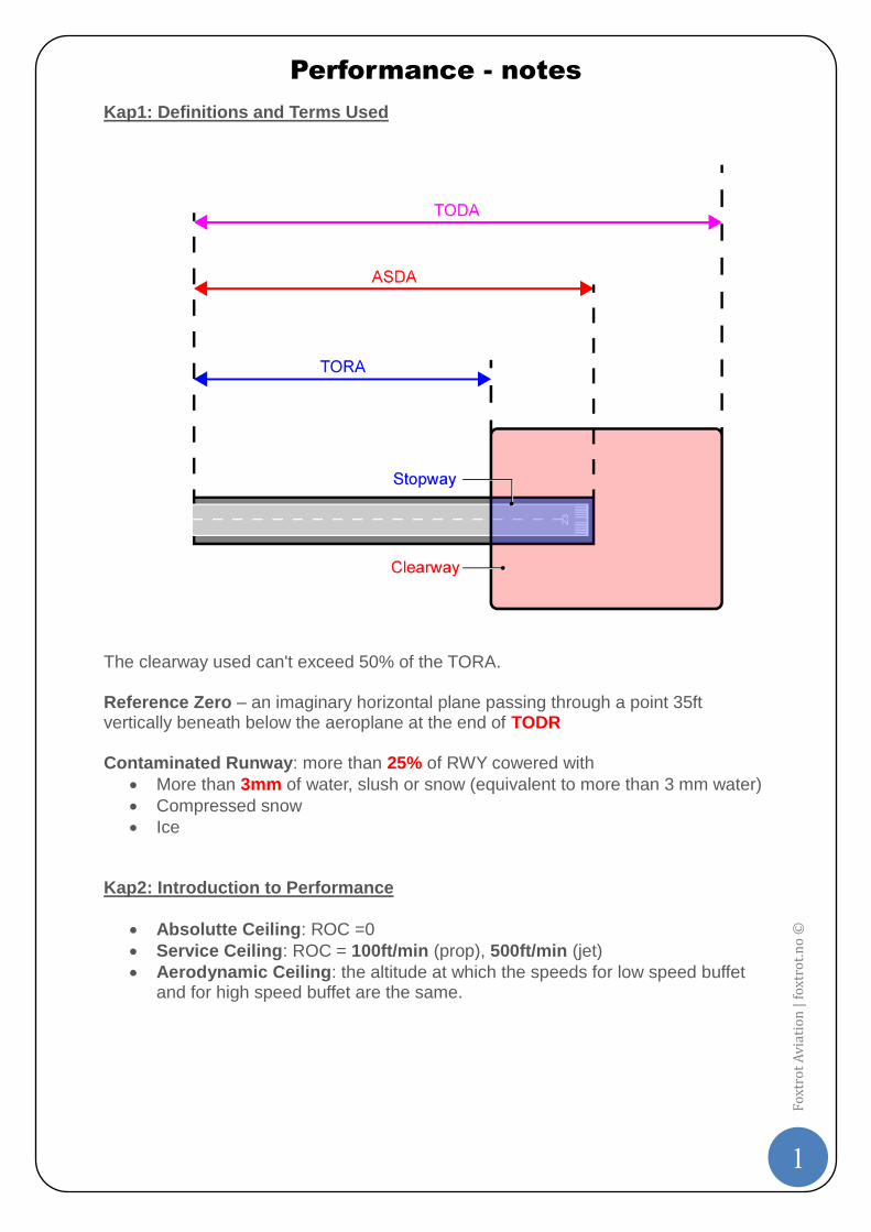
Kap1: Definitions and Terms Used
The clearway used can't exceed 50% of the TORA. Reference Zero – an imaginary horizontal plane passing through a point 35ft vertically beneath below the aeroplane at the end of TODR Contaminated Runway: more than 25% of RWY cowered with
More than 3mm of water, slush or snow (equivalent to more than 3 mm water)
Compressed snow
Ice Kap2: Introduction to Performance
Absolutte Ceiling: ROC =0
Service Ceiling: ROC = 100ft/min (prop), 500ft/min (jet)
Aerodynamic Ceiling: the altitude at which the speeds for low speed buffet and for high speed buffet are the same.
Performance - notes
2
Fo
xtro
t A
via
tio
n |
fo
xtro
t.n
o ©
Kap3: Performance Basics
TOD will increase by 20% for each 10% increase in mass
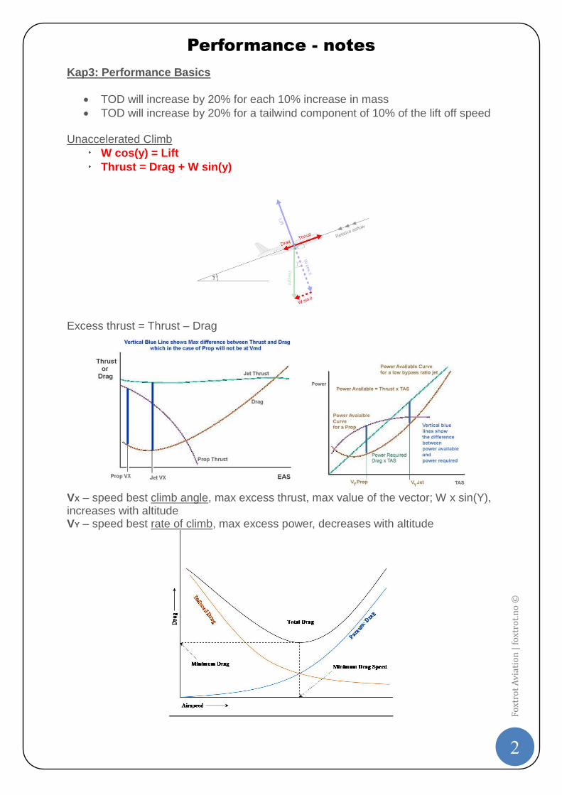
TOD will increase by 20% for a tailwind component of 10% of the lift off speed Unaccelerated Climb
W cos(y) = Lift
Thrust = Drag + W sin(y)
Excess thrust = Thrust – Drag
VX – speed best climb angle, max excess thrust, max value of the vector; W x sin(Y), increases with altitude VY – speed best rate of climb, max excess power, decreases with altitude
Performance - notes
3
Fo
xtro
t A
via
tio
n |
fo
xtro
t.n
o ©
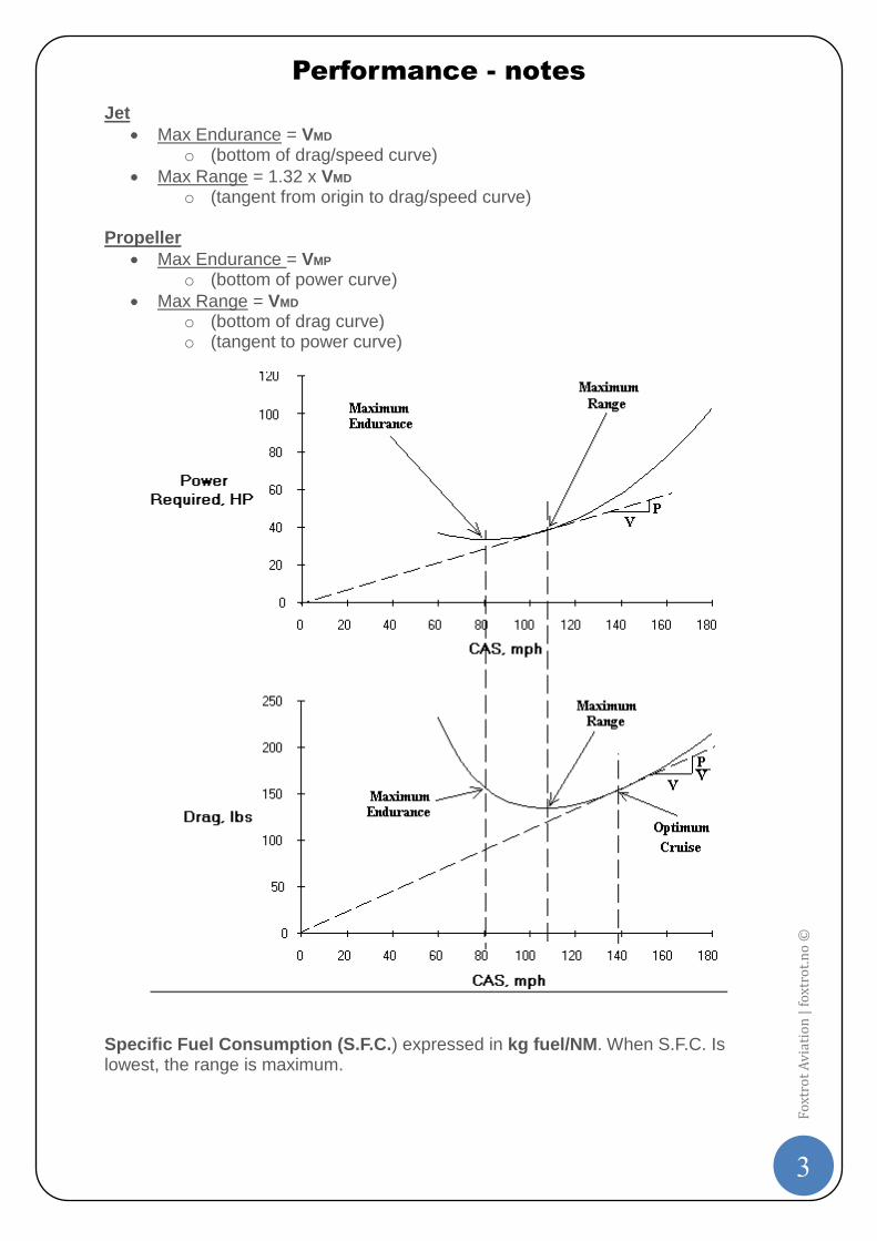
Jet
Max Endurance = VMD o (bottom of drag/speed curve)
Max Range = 1.32 x VMD o (tangent from origin to drag/speed curve)
Propeller
Max Endurance = VMP o (bottom of power curve)
Max Range = VMD o (bottom of drag curve) o (tangent to power curve)
Specific Fuel Consumption (S.F.C.) expressed in kg fuel/NM. When S.F.C. Is lowest, the range is maximum.
Performance - notes
4
Fo
xtro
t A
via
tio
n |
fo
xtro
t.n
o ©
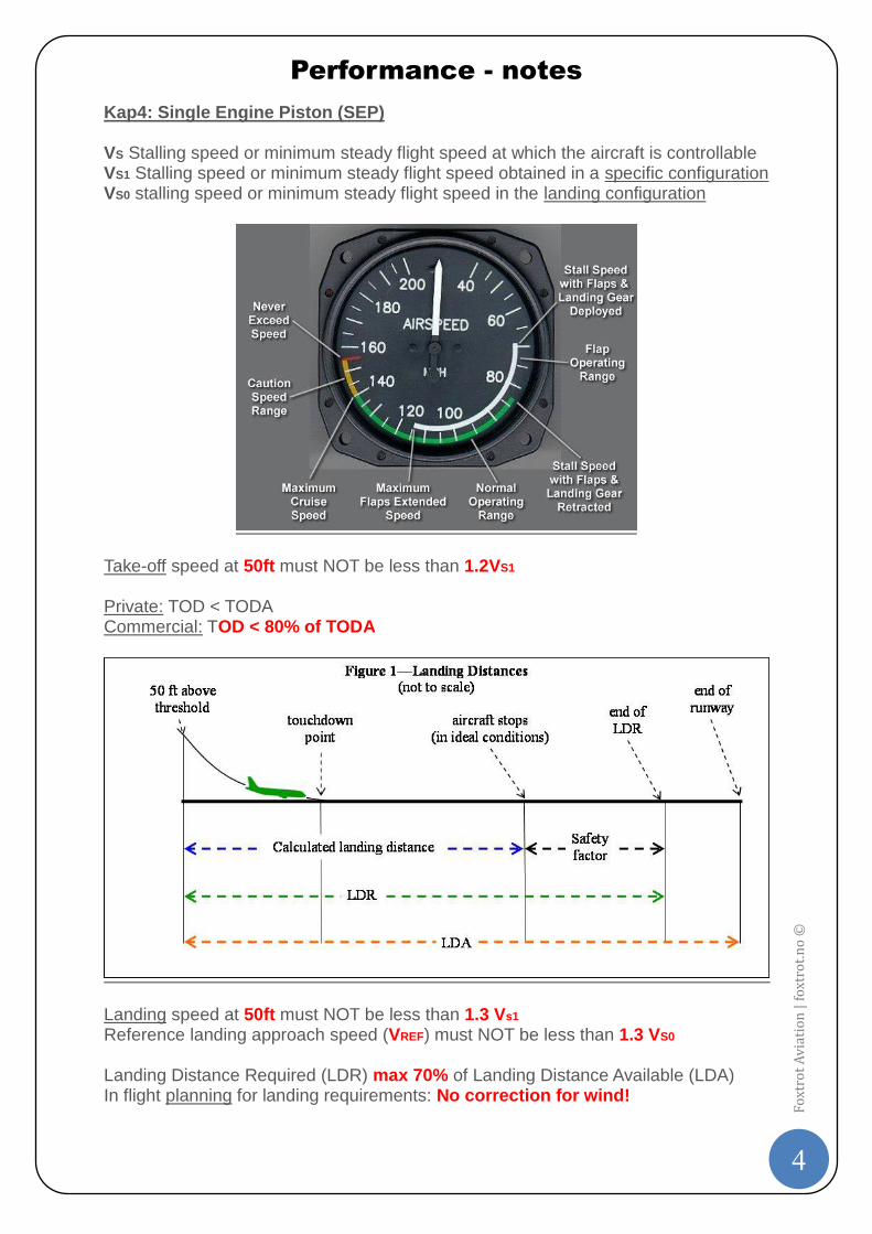
Kap4: Single Engine Piston (SEP) VS Stalling speed or minimum steady flight speed at which the aircraft is controllable VS1 Stalling speed or minimum steady flight speed obtained in a specific configuration VS0 stalling speed or minimum steady flight speed in the landing configuration
Take-off speed at 50ft must NOT be less than 1.2VS1
Private: TOD < TODA Commercial: TOD < 80% of TODA
Landing speed at 50ft must NOT be less than 1.3 Vs1 Reference landing approach speed (VREF) must NOT be less than 1.3 VS0 Landing Distance Required (LDR) max 70% of Landing Distance Available (LDA) In flight planning for landing requirements: No correction for wind!
Performance - notes
5
Fo
xtro
t A
via
tio
n |
fo
xtro
t.n
o ©
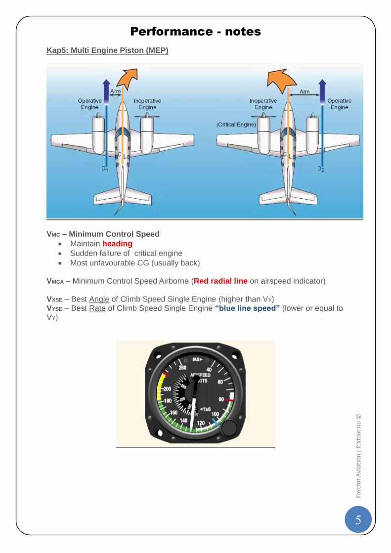
Kap5: Multi Engine Piston (MEP)
VMC – Minimum Control Speed
Maintain heading
Sudden failure of critical engine
Most unfavourable CG (usually back) VMCA – Minimum Control Speed Airborne (Red radial line on airspeed indicator) VXSE – Best Angle of Climb Speed Single Engine (higher than VX) VYSE – Best Rate of Climb Speed Single Engine “blue line speed” (lower or equal to VY)
Performance - notes
6
Fo
xtro
t A
via
tio
n |
fo
xtro
t.n
o ©
Kap6: Take-Off (Class A) VSR – Reference Stall speed VMC – Minimum Control speed. May not exceed 1.13 VSR VMCG – Minimum Control speed Ground. OEI control A/C without nose-wheel steering VMBE – Maximum Brake Energy speed. Depends on mass, temp, pressure, slope and wind VEF – Critical Engine Failure speed at which the critical engine is assumed to fail during take-off V1 - Take-Off Decision speed. Reject or continue take-off.
Recognition time: 1 sec from VEF to V1
V1 is decreased on a wet runway to account for the stopping case.
VMCG ≤ V1 ≤ VR
May be limited by VMBE VR – Rotation speed. Aeroplane rotated for lift-off. May not be less than:
V1
1.05 VMC(A) VMU – Minimum Unstick speed. The speed at which the aircraft can safely lift off the ground (the speed during rotation, the nose wheel comes off the runway). VLOF – Lift Off speed. The speed at which the main wheels get airborne. VTYRE – Max Tyre speed (centripetal force) V2 – Take-off safety speed (CS 25 ) at 35 ft. not less than: (1.2 VS)
1.13 VSR for:
◦ Two/three-engined turbo-prop
◦ Turbo-jet (without prov. for obtain. signif. reduction in N-1 stall speed)
1.08 VSR for:
◦ Turbo-prop with more than three engines
◦ Turbo-jet (with prov. for obtain. signif. reduction in N-1 stall speed)
1.1 VMC(A) VFTO – Final Take-Off speed. Must provide climb gradient of final segment. Not less than 1.18 VSR. Speed at the end of take-off path in the en-route configuration with OEI. TORR is the greater of:
All Engines Operation (AEO) TORR: Gross x 1.15
One Engine Inoperative (OEI) TORR: Gross = net One engine out take-off run is the distance between the brake release point and the middle of the segment between VLOF point and 35 ft point. Decrease the take-off ground run:
1. decreasing take off mass 2. increasing density 3. increasing flap setting 4. decreasing pressure altitude
TODR – Take-Off Distance Required (longest of):
1. OEI: accelerate to V1 and continue to 35ft (wet RWY: 15ft) 2. AEO: 115% of dist to bring aircraft to 35ft
Performance - notes
7
Fo
xtro
t A
via
tio
n |
fo
xtro
t.n
o ©
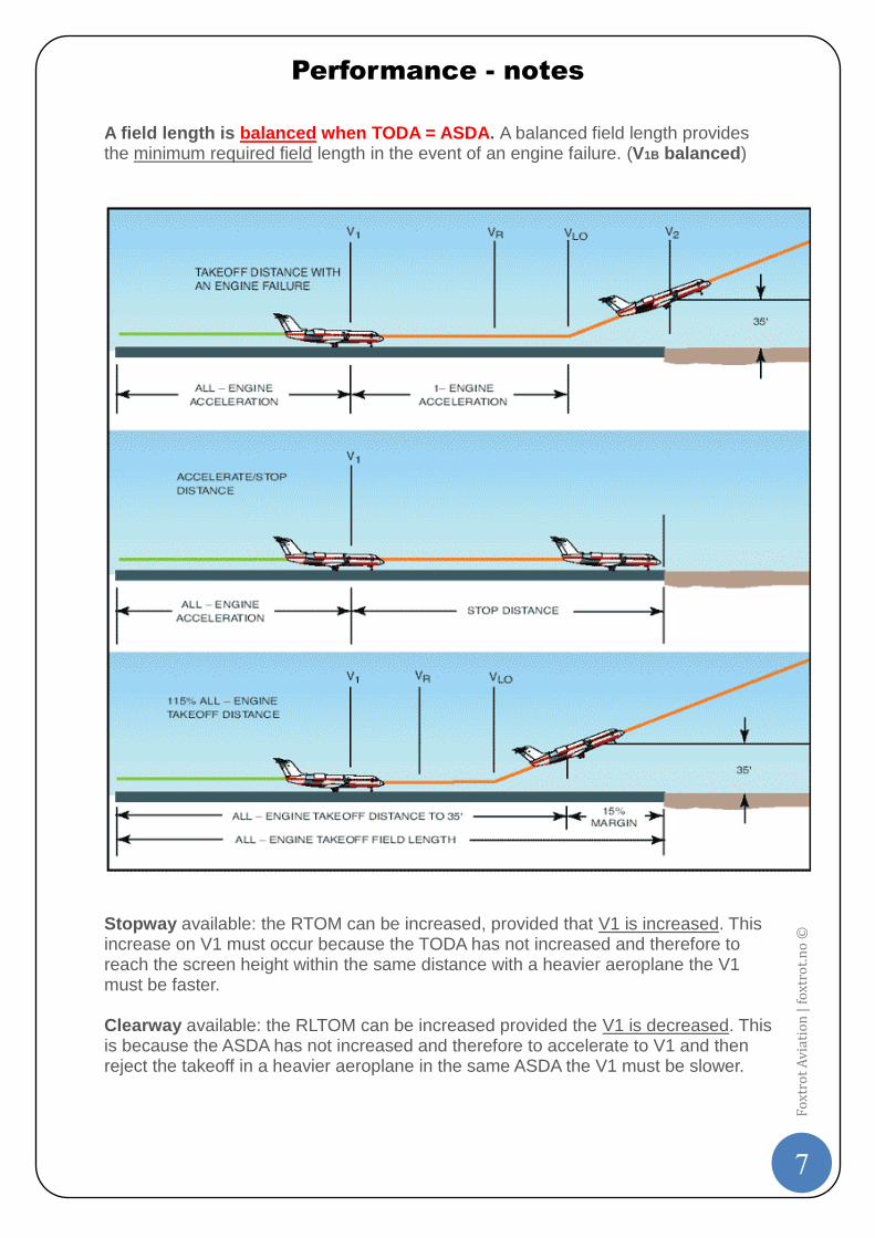
A field length is balanced when TODA = ASDA. A balanced field length provides the minimum required field length in the event of an engine failure. (V1B balanced)
Stopway available: the RTOM can be increased, provided that V1 is increased. This increase on V1 must occur because the TODA has not increased and therefore to reach the screen height within the same distance with a heavier aeroplane the V1 must be faster. Clearway available: the RLTOM can be increased provided the V1 is decreased. This is because the ASDA has not increased and therefore to accelerate to V1 and then reject the takeoff in a heavier aeroplane in the same ASDA the V1 must be slower.
Performance - notes
8
Fo
xtro
t A
via
tio
n |
fo
xtro
t.n
o ©
Uphill slope increases the TODR more than the ASDR because of the continued acceleration after V1. We increase V1 with an upslope. Positive slope increases the ASDR.
Downhill slope increases allowable take-off mass. It will be easier to accelerate the a/c assisted by the downhill component of weight therefore we can increase the mass and still make 35ft and V2 within TODA, however we will have to reduce V1 in case we have to stop with a heavier A/C. Negative slope decreases the ASDR.
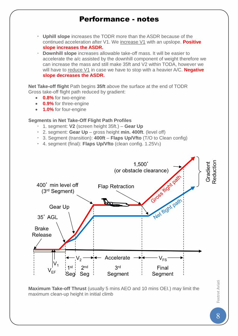
Net Take-off flight Path begins 35ft above the surface at the end of TODR Gross take-off flight path reduced by gradient:
0.8% for two-engine
0.9% for three-engine
1.0% for four-engine Segments in Net Take-Off Flight Path Profiles
1. segment: V2 (screen height 35ft.) – Gear Up
2. segment: Gear Up – gross height min. 400ft. (level off)
3. Segment (transition): 400ft – Flaps Up/Vfto (T/O to Clean config)
4. segment (final): Flaps Up/Vfto (clean config. 1.25VS)
Maximum Take-off Thrust (usually 5 mins AEO and 10 mins OEI.) may limit the maximum clean-up height in initial climb
Performance - notes
9
Fo
xtro
t A
via
tio
n |
fo
xtro
t.n
o ©
Net Take-Off Flight Path Funnel – Obstacle Accountability Area (dimensions): 1) End of TODA: 90m (or 60m + ½ wing span, if wingspan < 60m) 2) Expands at 0.125 x D (D = distance from TODR), 90m + (0.125 x D) 3) Flight Path Funnel With
a) Visual guidance (VMC day) i) Track 0-15°: 300m ii) Over 15°: 600m
b) Other conditions (IMC or VMC night): i) Track 0-15°: 600m ii) Over 15°: 900m
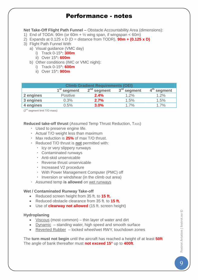
Climb Gradient Requirements (OEI)
1st segment 2nd segment 3rd segment 4th segment
2 engines Positive 2.4% 1.2% 1.2%
3 engines 0.3% 2.7% 1.5% 1.5%
4 engines 0.5% 3.0% 1.7% 1.7%
(2nd
segment limit T/O mass)
Reduced take-off thrust (Assumed Temp Thrust Reduction, TASS)
Used to preserve engine life.
Actual T/O weight less than maximum
Max reduction is 25% of max T/O thrust.
Reduced T/O thrust is not permitted with:
Icy or very slippery runways
Contaminated runways
Anti-skid unservicable
Reverse thrust unservicable
Increased V2 procedure
With Power Management Computer (PMC) off
Inversion or windshear (in the climb out area)
Assumed temp is allowed on wet runways Wet / Contaminated Runway Take-off
Reduced screen height from 35 ft. to 15 ft.
Reduced obstacle clearance from 35 ft. to 15 ft.
Use of clearway not allowed (15 ft. screen height) Hydroplaning
Viscous (most common) – thin layer of water and dirt
Dynamic – standing water, high speed and smooth surface
Reverted Rubber – locked wheel/wet RWY, touchdown zones The turn must not begin until the aircraft has reached a height of at least 50ft The angle of bank thereafter must not exceed 15° up to 400ft.
Performance - notes
10
Fo
xtro
t A
via
tio
n |
fo
xtro
t.n
o ©
The climb limited take-off mass can be increased by a lower flap setting for take-off and selecting a higher V2. The engines are pressure limited at lower temperature, at higher temperatures they are temperature limited (the take-off performance climb limit graph show a kink).
Performance - notes
11
Fo
xtro
t A
via
tio
n |
fo
xtro
t.n
o ©
Kap7: Climb (Class A)
If the correction for acceleration is neglected, and lift ~ weight:
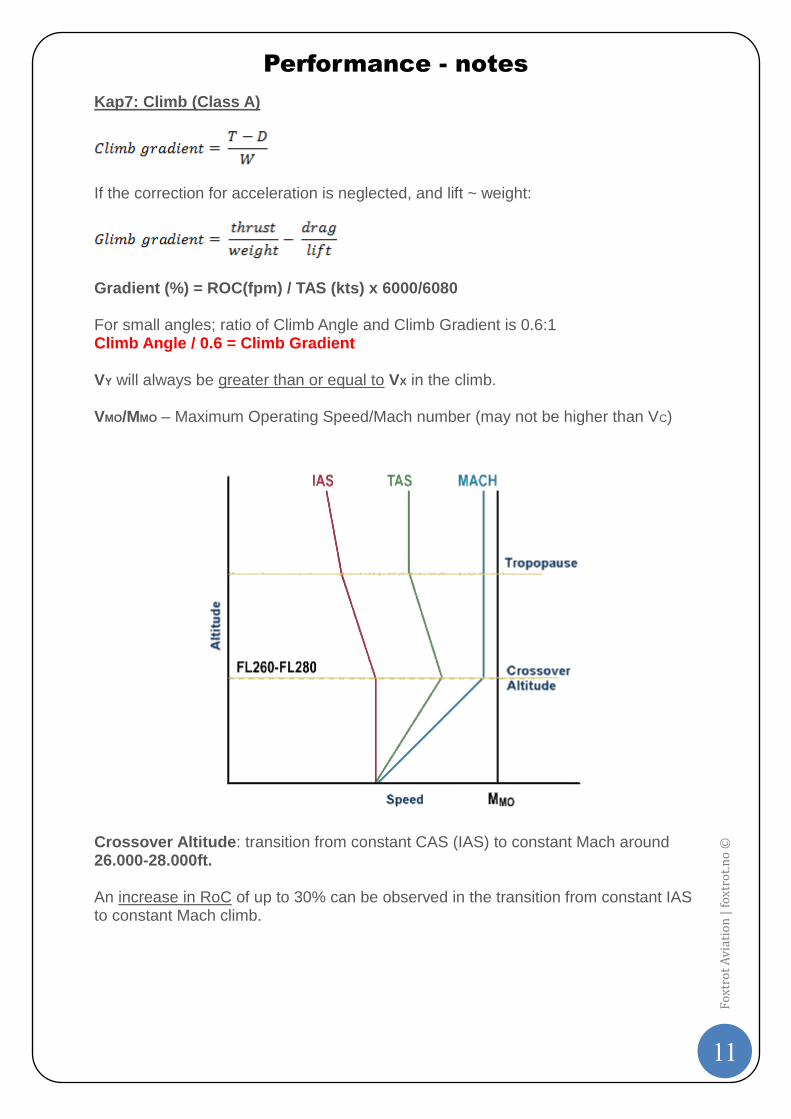
Gradient (%) = ROC(fpm) / TAS (kts) x 6000/6080 For small angles; ratio of Climb Angle and Climb Gradient is 0.6:1 Climb Angle / 0.6 = Climb Gradient VY will always be greater than or equal to VX in the climb. VMO/MMO – Maximum Operating Speed/Mach number (may not be higher than VC)
Crossover Altitude: transition from constant CAS (IAS) to constant Mach around 26.000-28.000ft. An increase in RoC of up to 30% can be observed in the transition from constant IAS to constant Mach climb.
Performance - notes
12
Fo
xtro
t A
via
tio
n |
fo
xtro
t.n
o ©
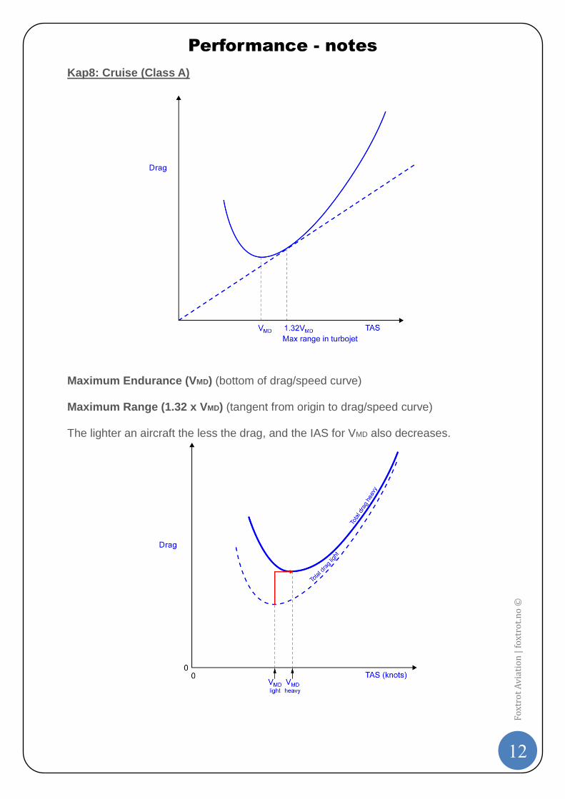
Kap8: Cruise (Class A)
Maximum Endurance (VMD) (bottom of drag/speed curve) Maximum Range (1.32 x VMD) (tangent from origin to drag/speed curve) The lighter an aircraft the less the drag, and the IAS for VMD also decreases.
Performance - notes
13
Fo
xtro
t A
via
tio
n |
fo
xtro
t.n
o ©
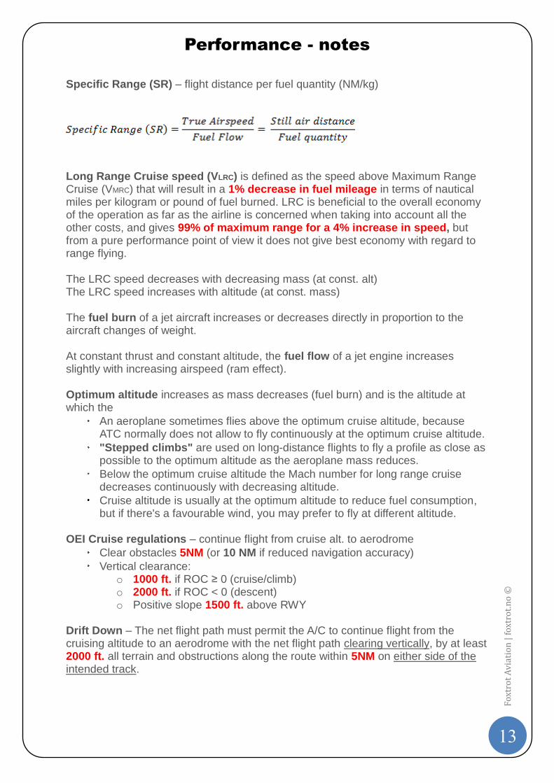
Specific Range (SR) – flight distance per fuel quantity (NM/kg)
Long Range Cruise speed (VLRC) is defined as the speed above Maximum Range Cruise (VMRC) that will result in a 1% decrease in fuel mileage in terms of nautical miles per kilogram or pound of fuel burned. LRC is beneficial to the overall economy of the operation as far as the airline is concerned when taking into account all the other costs, and gives 99% of maximum range for a 4% increase in speed, but from a pure performance point of view it does not give best economy with regard to range flying. The LRC speed decreases with decreasing mass (at const. alt) The LRC speed increases with altitude (at const. mass) The fuel burn of a jet aircraft increases or decreases directly in proportion to the aircraft changes of weight. At constant thrust and constant altitude, the fuel flow of a jet engine increases slightly with increasing airspeed (ram effect). Optimum altitude increases as mass decreases (fuel burn) and is the altitude at which the
An aeroplane sometimes flies above the optimum cruise altitude, because ATC normally does not allow to fly continuously at the optimum cruise altitude.
"Stepped climbs" are used on long-distance flights to fly a profile as close as possible to the optimum altitude as the aeroplane mass reduces.
Below the optimum cruise altitude the Mach number for long range cruise decreases continuously with decreasing altitude.
Cruise altitude is usually at the optimum altitude to reduce fuel consumption, but if there's a favourable wind, you may prefer to fly at different altitude.
OEI Cruise regulations – continue flight from cruise alt. to aerodrome
Clear obstacles 5NM (or 10 NM if reduced navigation accuracy)
Vertical clearance: o 1000 ft. if ROC ≥ 0 (cruise/climb) o 2000 ft. if ROC < 0 (descent) o Positive slope 1500 ft. above RWY
Drift Down – The net flight path must permit the A/C to continue flight from the cruising altitude to an aerodrome with the net flight path clearing vertically, by at least 2000 ft. all terrain and obstructions along the route within 5NM on either side of the intended track.
Performance - notes
14
Fo
xtro
t A
via
tio
n |
fo
xtro
t.n
o ©
The maximum drift down altitude is the altitude to which, following the failure of an engine above the one engine inoperative absolute ceiling, an aeroplane will descend and maintain, whilst using max available thrust/power on the operating engine. Extended Range Twin operations (ETOPS) Definition: ETOPS is the minimum flying time from a suitable airport in still air, with one engine inoperative at the one engine out cruise speed.
Performance - notes
15
Fo
xtro
t A
via
tio
n |
fo
xtro
t.n
o ©
Kap9: Descent (Class A) Normally flown at idle thrust
Rate of Decent decreases with altitude
If the correction for acceleration is neglected, and lift ~ weight:
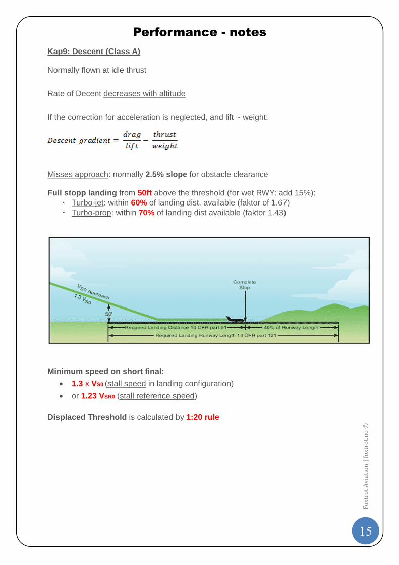
Misses approach: normally 2.5% slope for obstacle clearance Full stopp landing from 50ft above the threshold (for wet RWY: add 15%):
Turbo-jet: within 60% of landing dist. available (faktor of 1.67)
Turbo-prop: within 70% of landing dist available (faktor 1.43)
Minimum speed on short final:
1.3 x VS0 (stall speed in landing configuration)
or 1.23 VSR0 (stall reference speed)
Displaced Threshold is calculated by 1:20 rule
Performance - notes
16
Fo
xtro
t A
via
tio
n |
fo
xtro
t.n
o ©
Missed Approach
Landing Climb Requirement – landing flaps, gear down, AEO at go-around thrust
o Climb gradient not less than 3.2% with speed of 1.23% VS
Approach Climb Requirement – approach flap, gear up, OEI and remaining eng. at go-around thrust:
o 1.5 VS o Gradient
Two engine aircraft: 2.1%
Three engine aircraft: 2.4%
Four engine aircraft: 2.7% Pavement Classification Number (PCN) overloads allowed:
10% on flexible pavements
5% on rigid pavements
Abbreviations OEI – One Engine Inoperative AEO – All Engine Operative A/C – Aircraft T/O – Take-off