performance limitations of rotationally symmetric nonimaging devices
TRANSCRIPT

Ries et al. Vol. 14, No. 10 /October 1997 /J. Opt. Soc. Am. A 2855
Performance limitations of rotationally symmetricnonimaging devices
Harald Ries
Paul Scherrer Institute, CH-5232 Villigen, Switzerland
Narkis Shatz and John Bortz
Science Applications International Corporation, 10260 Campus Point Drive, San Diego, California 92121
Wolfgang Spirkl
Department of Physics, Ludwig-Maximilians University, Amalienstrasse 54, D-80799 Munchen, Germany
Received October 7, 1996; revised manuscript received February 24, 1997; accepted March 31, 1997
An upper limit on concentration for any optical device has previously been derived from the conservation ofetendue. In this contribution we derive more stringent upper limits for the efficiency and the concentration ofrotationally symmetric optical devices that are a consequence of skewness conservation. If the desired sourceand target have different skewness distributions, then losses or dilution or both will limit the performance ofthe optical system. We calculate the limiting curve of efficiency versus concentration and provide a designexample that is virtually at this limit. We conjecture that even rotationally symmetric problems may benefitfrom asymmetric optical systems. © 1997 Optical Society of America [S0740-3232(97)00910-1]
1. INTRODUCTIONThe upper limits on concentration and efficiency for anonimaging optical system have been derived from theconservation of phase-space volume (etendue) (Ref. 1,Chap. 2.7) and from the second law of thermodynamics.2,3
Many optical devices, both reflective and refractive,have rotational symmetry. One reason, obviously, is theease of manufacture. For nonimaging optical devicesused in concentration and illumination, the geometry ofthe application often is also rotationally symmetric.
Symmetric optical devices conserve the skewness of theradiation around the optical axis (Ref. 1, Chap. 2.8). Theskewness is analogous to the angular momentum. If weimagine a particle of unit mass equal to the index of re-fraction traveling along the path of a ray with unit veloc-ity, then its angular momentum is equal to the skewnessof that ray. If the skewness of each ray is conserved,then the complete distribution of skewness entering theoptical system will be unchanged. This is a much stron-ger condition than the conservation of phase-space vol-ume (etendue) which is merely a scalar quantity. For thecase of a mismatch of the skewness distribution of sourceand target, limitations have been observed e.g., in Ref. 4.In this paper we investigate the theoretical upper limitthat arises as a consequence of skewness conservation forrotationally symmetric optical systems.
2. SKEWNESS DISTRIBUTION OF ASOURCE OR TARGETThe skewness s of a single ray is given by
s 5 r • ~k 3 a ! 5 rmin kt (1)
0740-3232/97/1002855-08$10.00 ©
where r is an arbitrary vector linking the optical axiswith the ray, k is the direction along the ray with magni-tude equal to the index of refraction n, a is the unit vectoralong the optical axis, rmin is the magnitude of the short-est vector rmin between the optical axis and the ray, andkt is the component of the direction vector k in the tan-gential direction, perpendicular both to the optical axisand the vector rmin . We define the skewness distributionas the differential etendue occupied by all rays within aninfinitesimal skewness interval around s. With this defi-nition the skewness distribution is normalized to the totaletendue.1 We distinguish between positive and negativevalues of skewness in order to be able also to treat asym-metric sources and targets.
For an arbitrary element of a rotational surface actingas a uniform source of radiation confined to an angle u tothe local normal, the tangential component of the direc-tion is distributed according to a circular contour, becausetogether both components parallel to the surface elementare uniformly distributed inside of a circle of radiusn sin(u). The skewness distribution of an arbitrary sur-face in air is therefore given by
dE ~s !
ds 5 Er sin~u!.usu
2 sin~u!
r A1 2s2
@r sin~u!#2 da,
(2)
where the integral extends over all area elements da ofthe surface for which the distance r to the optical axis islarger than usu. The maximum distance a surface ex-tends from the axis thus determines a maximum skew-ness. For surfaces generated by the rotation of a curvearound the axis, the area element may be expressed bythe length element dl as da 5 2prdl.
1997 Optical Society of America

2856 J. Opt. Soc. Am. A/Vol. 14, No. 10 /October 1997 Ries et al.
The skewness distribution of radiation from a disk ofradius R is for 2R sin(u) , s , R sin(u):
dEd
ds5 4pR sin~u!@A1 2 x2 2 x arccos~x !#,
where x 5usu
R sin~u!. (3)
For a Lambertian disk (u 5 p/2) this result is derivedalso in Ref. 1, Sec. F5.
For radiation from a sphere of radius R the skewnessdistribution is piecewise linear. The integral is solvedwith the transformation u 5 cos2(f), x is defined as inEq. (3):
dEs
ds5 8pR sin~u!E
0
arccos~x !A1 2x2
cos2~f!df
5 4pR sin~u!Ex2
1Au 2 x2
1 2 u
du
u
5 4pR sin~u!XarctanH 2u 2 1 2 x2
2@~1 2 u !~u 2 x2!#1/2J1 x arctanH 2x2 2 u 2 x2u
2x@~1 2 u !~u 2 x2!#1/2J Cu5x2
u51
5 4p2R sin~u!~1 2 uxu!. (4)
An open-ended cylinder of radius R and height H ori-ented along the axis has a skewness distribution for 2R, s , R given by
dEc
ds5 4pH sin~u!A1 2 x2 . (5)
We show in Fig. 1 the skewness distributions of a disk ofunit radius, a sphere of radius 0.5, and a cylinder with ra-dius 0.25 and height 2. The angle u is chosen as p/2 forall three shapes. The sphere and the cylinder are chosensuch that their areas match that of the disk.
Fig. 1. Skewness distributions of a disk with R sin (u) 5 1, asphere of radius R 5 0.5 a cylinder of radius R 5 0.25, andheight H 5 2. For each distribution, the area under the curveis the same.
3. UPPER LIMIT ON EFFICIENCYSuppose we want to transfer radiation from a source thathas a skewness distribution dE1 /ds to a target that has askewness distribution dE2 /ds by means of a rotationallysymmetric optical device. For those value of the skew-ness s for which dE1 /ds , dE2 /ds, all rays may be trans-ferred, but some regions of the target will not be filledwith radiation. This represents a dilution of the radia-tion in phase space by a factor dE2 /dE1 . On the otherhand, for those values of the skewness for which dE1 /ds. dE2 /ds not all the rays may be transferred, becausethey would not fit into the phase space available on thetarget. The fraction dE1 /dE2 2 1 of these rays is lost.We illustrate these conditions in Fig. 2. A similar argu-ment was used to demonstrate basic limitations ofFresnel-type optical devices.5
Thus the maximum etendue of radiation of any skew-ness s that can be transferred from the source to the tar-get is min(dE1 /ds, dE2 /ds). The maximum efficiency his the ratio of the maximum phase space that may betransferred to the phase space of the source,
h 5
E min~dE1 /ds, dE2 /ds !ds
E dE1 /dsds
. (6)
Similarly the maximum concentration (minimal dilution)is the ratio of the maximum phase space that may betransferred to the phase space of the target,
C 5
E min~dE1 /ds, dE2 /ds !ds
E dE2 /dsds
. (7)
This ratio is not really a concentration, because it is al-ways less than or equal to one. But it may be viewed asa correction factor that reduces any hypothetical furtherconcentration below the maximum value derived from the
Fig. 2. If the skewness distribution of the source does not matchthat of the target, then the minimum of the two constitutes theupper limit for the transferred etendue. Where the distributionof the source exceeds that of the target, losses occur. Where thedistribution of the target exceeds that of the source, the radiationis diluted.

Ries et al. Vol. 14, No. 10 /October 1997 /J. Opt. Soc. Am. A 2857
conservation of etendue. Clearly, if the source and thetarget have equal etendue, as one would choose for idealdevices, the ideal efficiency and the ideal concentrationare equal to unity. As we have seen, however, if thesource and the target have different skewness distribu-tions, ideal devices are not possible at all. In this caseone cannot simultaneously avoid losses and dilution.The user may choose a target of larger or smaller etenduecompared with the source depending on whether effi-ciency or concentration is valued higher. By varying thesize of the target relative to that of the absorber one canderive a curve of efficiency versus concentration, h(C).This curve represents an upper limit in the sense that norotationally symmetric device may reach a higher effi-ciency at a given concentration nor a higher concentrationat a given efficiency.
Both dilution and losses occur if the skewness distribu-tion of source and target intersect. It is possible to avoidlosses up to a certain dilution. Also one can avoid dilu-tion below a certain efficiency. Exchanging the role ofthe source with that of the target is equivalent to ex-changing the role of the efficiency with that of the concen-tration, as is apparent from Eqs. (7) and (6).
4. EXAMPLESA. Three-Dimensional Compound ParabolicConcentratorIt is known that the rotationally symmetric three-dimensional compound parabolic concentrator (CPC) isnot ideal, in the sense that it does not transfer all radia-tion entering its aperture within a certain acceptanceangle with regard to the normal onto the absorber (Ref. 1,Chap. 4). The nonideality may be insignificant for mostapplications, yet it is challenging theoretically. Further-more, it has been proven by a numerical example6 thatthe three-dimensional (3D) CPC is also not optimal,which is to say that better rotationally symmetric solu-tions exist that have been shown to correct approximately15% of the nonideality.
One may wonder whether the limitations outlined inthis contribution help to explain the nonideality of the 3DCPC. Unfortunately this is not so. As indicated in Eq.(3) the skewness distributions of two disks of different ra-dii and different limit angles match precisely if the twodisks have equal etendue. Therefore skewness conserva-tion does not rule out the possibility of ideal rotationallysymmetric concentrators.
B. Flux Transfer between a Cylinder and a DiskMany commercial light sources consist of a straight coiledfilament. Radiation from such sources may be viewed asoriginating from the outer surface of a cylinder. Thiswas the motivation to treat this example. In Fig. 3 weshow the upper limit for a reflector with a disk-shapedtarget and a source in the shape of a cylinder of variousheight-to-radius ratios. In particular for large H/R thelimitations from skewness conservation are severe. Atequal etendue, for H/R 5 10, both efficiency and concen-tration are lower than 0.5. To avoid losses, the targethas to be larger than the source by at least a factor of 3.
5. NUMERICAL SOLUTION FOR FLUXTRANSFER BETWEEN A SPHERE AND ADISKThe problem considered here is to design a nonimagingreflector that maximizes flux transfer from a sphericalsource to a disk target of equal etendue. This problemhas been considered previously.6 The solution describedin Eq. (6) was achieved by applying numerical optimiza-tion to a solution space, defined by means of a parameter-ization scheme, resulting in an optimized spline reflector(OSR) form. The optimized solution achieved an effi-ciency of 0.668, which represented a substantial improve-ment over two classical edge-ray solutions with efficien-cies of 0.505 and 0.563.
We have shown in Subsection 4.B. that ideal energytransfer for this problem is impossible with a rotationallysymmetric reflector. At most such a reflector may trans-fer 0.753 of the radiation and dilute the radiation also by0.753 if source and target have equal etendue. Theupper-limit efficiency versus concentration for a sphericalsource and a disk-shaped target are shown in Fig. 4.Losses may be avoided only for concentrations below4/p2 ' 0.4; dilution may be avoided only for efficienciesbelow 0.25.
We now state the design problem as one of determiningthe form of a rotationally symmetric OSR that maximizesthe flux transfer from a 10-mm-diameter spherical Lam-bertian source into an emergent conical beam subtendinga 30-degree half-angle. We enforce the constraint thatthe source and the target must have equal etendues,which directly leads to the requirement that the targetdisk diameter must be 40 mm. The aperture-to-sourcediameter ratio is a consequence of the thermodynamiclimit which for this case is 1/sin2(30°) 5 4. We postulatea loss-free, specular, axially symmetric, continuously dif-ferentiable reflector. Appendix A describes our choice ofcoordinate system, an improved parameterizationscheme,6 and the constraints used to obtain the 3D OSRdesign.
Fig. 3. Upper-limit efficiency as a function of concentration for adisk target and a cylindrical source of length-to-radius ratiosH/R 5 5, H/R 5 10, and H/R 5 20. The curve is derived byvarying the ratio of the radii of source and target.

2858 J. Opt. Soc. Am. A/Vol. 14, No. 10 /October 1997 Ries et al.
For purposes of comparison we also consider edge-raysolutions. The two-dimensional (2D) involute CPC7 is anedge-ray solution capable of collecting the light incidentover a given input acceptance angle and ideally transfer-ring it onto a circular target. Consequently, the 3D invo-lute CPC, operated in reverse, constitutes the edge-raysolution for the projection of energy from a sphericalsource into an emergent conical beam. We consider twocases. A 3D involute CPC designed for an acceptancehalf-angle of 30° and then truncated to provide the requi-site exit aperture diameter of 40 mm. We also consideran untruncated 3D involute CPC for which case the de-sign acceptance half-angle would then be 51.76 degrees.
The resulting shape profile of the 3D OSR design opti-mized for a 30° half-angle beam is shown in Fig. 5. Astriking feature of this solution is that the source pro-trudes behind the back of the reflector. The performanceof this solution was computed by using 200,000 rays,which provide an accuracy of better than 0.001 in dilutionand efficiency. Our solution results in a dilution of 0.751and transfers 0.751 of the radiation and therefore isnearly at the limit.
Fig. 4. Upper-limit efficiency as a function of concentration for aspherical source and a disk target.
Fig. 5. Reflector for transferring radiation from a sphere of di-ameter 10 units to a disk with equal etendue within 30° found byoptimization.
A comparison of the efficiency-versus-concentrationcurve for the 3D OSR solution with the correspondingcurves for the two edge-ray solutions is provided in Fig. 6.The upper-limit curve in Fig. 6 is the same curve shownpreviously in Fig. 4. The curves shown for the OSR andthe two edge-ray solutions were each obtained by comput-ing both the efficiency and the concentration as a functionof the target’s phase-space volume and then plotting theresulting efficiency values as a function of the correspond-ing concentration values. The target’s phase-space vol-ume was varied by changing the projected half-angle ofthe target. All other system characteristics were heldconstant, including the radii of both the source and the
Fig. 6. Efficiency versus concentration.
Fig. 7. Efficiency versus projected half-angle.

Ries et al. Vol. 14, No. 10 /October 1997 /J. Opt. Soc. Am. A 2859
Fig. 8. Skewness distributions for sphere, disk, and all rays output by 30° optimized spline reflector.
Fig. 9. Skewness distributions for sphere, disk, and subset of rays output into 30° half-angle by 30° optimized spline reflector.
target, as well as the concentrator shape. Note that theperformance of the 3D OSR is superior throughout mostof the efficiency-versus-concentration regime. The opti-mized nature of the solution is particularly evident by thetangency of the 3D OSR curve to the limiting curve at thedesign point. A comparison of the efficiency versus theprojected half-angle is shown in Fig. 7. It is noteworthyto observe that in Fig. 7 the 3D OSR tracks the limitingcurve closely for operating half-angles less than 30°,whereas the deficiencies of the edge-ray solutions are
clearly evident. Figure 8 shows the distribution of all theskew rays of our solution in comparison with the theoret-ical sphere and the disk skewness distributions. Asshown in Fig. 9, when we exclude from our solution allrays beyond a projected half-angle of 30°, we find that theskewness distribution closely approximates the intersec-tion of the skewness distributions of the sphere and thedisk. The slightly jagged appearance of the OSR outputskewness distribution is due to the finite number of raysemployed in the computation. From this we can conclude
2860 J. Opt. Soc. Am. A/Vol. 14, No. 10 /October 1997 Ries et al.
that we have found a system that is virtually on the lim-iting curve.
6. INHOMOGENEOUS FLUX DENSITYThe upper limits in the previous sections were derivedunder the assumption that the source phase space is ho-mogeneously filled with radiation. One can, however,generalize these ideas and derive an upper limit on per-formance for the case of an inhomogeneous flux density.This is done by sorting the source-phase-space regions indecreasing order of their flux density and then filling thetarget’s phase space preferentially with those regions thathave the highest density until the entire target phasespace of a given skewness is exhausted.
Assume that the power density of the source is given byL(x) where x denotes a point in source phase-space S .This point also has a well-defined skewness s(x). For agiven skewness s we define the cumulative sorted flux asthe flux of all radiation exceeding a given threshold L:
d Psource
ds~L, s ! 5 E
xPS ; L~x !.Ld ~s~x ! 2 s !L~x !dE ~x !.
(8)
The Dirac d function ensures that only radiation ofskewness s is counted. Analogously, we define the cumu-lative etendue as the phase space occupied by this radia-tion:
dE source
ds~L, s ! 5 E
xPS ;L~x !.Ld ~s~x ! 2 s !dE ~x !. (9)
For an optimal rotationally symmetric device we haveto find that particular threshold L* (s) for which the cu-mulative etendue of the highest density source radiationexactly fills the target phase space E target:
dE source
ds@L* ~s !, s# 5
!
minFdE target
ds~s !,
dE source
ds G .(10)
With this threshold the maximum flux that can betransferred to the target is given by
P 5 E d Psource
ds~L* , s !ds. (11)
In analogy to Eq. (6) and Eq. (7), respectively, the opti-mal efficiency and concentration are given by
h 5P
E dPsource
ds~0, s !ds
,
C 5P
maxxPS L~x !E dE target
ds~L* , s !ds
. (12)
This expression for the concentration is normalizedsuch that in the limit of a small target the maximumvalue is unity. This case requires that the entire targetbe filled with radiation corresponding to the maximumdensity over the entire source.
The uniform source treated in the previous sectionscorresponds to the special case of a source that has a con-stant flux density in a well-defined region of space andzero elsewhere.
7. OUTLOOKUpper limits for efficiency and concentration were derivedfrom the conservation of skewness without reference tohow such systems might be constructed. It is not evenclear if an actual optical system with the performance cor-responding to a given point on the limiting curve exists atall. Certainly, if systems exist, in general each point onthe limit curve corresponds to a different optical system.
For many applications 3D solutions have been con-structed following the heuristic rule that, in general, ro-tating a 2D solution generates a nearly perfect solutionfor the corresponding rotationally symmetric 3D problem.Perhaps this rule originated in the observation of thesimilar performance results achieved by the 2D and 3DCPC’s. We have shown that one cannot expect this prac-tice to provide good solutions if the source and the targethave different skewness distributions.
Suppose that we have a perfect 2D solution for trans-ferring radiation from a given source to a given target ofequal 2D phase-space volume. Owing to rotational sym-metry, it is apparent that the optical system obtained byrotation of the 2D profile about the optical axis will trans-fer the radiation of zero skewness from the 3D source tothe 3D target without losses or dilution. In the generalcase the generated 3D source and target have differentetendue, and their skewness distributions match only forskewness zero. In principle these distributions may havemore than one intersection, but in many cases such as fora spherical source and a disk target, the distributions in-tersect only once. If the distributions match at skewnesszero, then the ratio of the etendue of the target to that ofthe source corresponds to the highest concentration thatmay be reached with no losses. If one can show that allskew rays are transferred to the target, one actually hasderived a solution that is at the limiting curve.
For a different choice of target-to-source area ratio theskewness distributions of source and target intersect ingeneral at a nonzero skewness. One may conjecture thattailoring the edge rays corresponding to that skewnessvalue may lead to a good system that comes close to thelimit curve8,9 (Ref. 1, Chap. 5.6). By designing an edge-ray reflector for nonzero skewness, Moorhead andTanner4 improved the concentration in comparison withthat of a meridional design.
The limitations derived in this contribution are rootedin skewness conservation, which is a property of rotation-ally symmetric systems only. For problems where sourceand target have strongly different skewness distributions,one may be led to search explicitly for asymmetrical solu-tions even for symmetric problems.10
APPENDIX A: PARAMETERIZATIONSCHEME FOR A THREE-DIMENSIONALOPTIMIZED SPLINE REFLECTORThe shape of the 3D OSR is represented by using a trun-cated involute CPC (TICPC) to define a coordinate sys-

Ries et al. Vol. 14, No. 10 /October 1997 /J. Opt. Soc. Am. A 2861
tem. To enforce the requirement that the exit-apertureradius of the TICPC must remain constant as its designparameters are varied, we introduce the scaled source ra-dius ts(t, u i , Rexit), as a function of the truncation pa-rameter t, the acceptance angle u i , and the required exit-aperture radius Rexit . The function rs(t, u i , Rexit) isdefined as the design source radius that keeps the exit-aperture radius of the TICPC equal to Rexit for any givenpair of values of t and u i . The function rs(t, u i , Rexit) isused only in specifying the size of the TICPC and is dis-tinct from the actual radius of the spherical source, whichis a constant designated r. For purposes of notationalbrevity, we now drop the explicit t, u i , and Rexit depen-dence of rs(t, u i , Rexit), referring to it simply as rs . Theradial and axial coordinate pairs on the profile of theTICPC can be conveniently expressed in parametric formas the functions
rCPC 5 rs sin~u! 2 t~u!cos~u!
zCPC 5 2rs cos~u! 2 t~u!sin~u! (A1)
respectively, where u is the angular parameter with therange
0 5 umin < u < umax 5 ~3p/2 2 u i!~1 2 t! (A2)
and t(u) is the edge-ray distance as a function of the an-gular parameter:
edge-ray distance for these Ndev points are un 5 u (Sn* )and tn 5 t@u (Sn* )#. We define Ndev deviation axes, eachof which passes through a sampling point and is perpen-dicular to the local tangent to the TICPC profile at thatpoint. Associated with each of these Ndev deviation axes,we define a deviation knot that must lie on its correspond-ing deviation axis. The position of the deviation knot nalong its associated deviation axis is given by thedeviation-knot position parameter wn , which representsthe distance of the deviation knot from the sampled coor-dinate (rn , zn) on the TICPC profile. The allowed rangeof variation for each deviation-knot position parameterwn is 6Wn/2, with Wn obtained from the equation
Wn 5 a 1 b~Sn* /SNdev* !1/r, n 5 1, ..., Ndev , (A6)
where a and b are real deviation-knot range-control con-stants. The OSR profile is required to pass through eachof the deviation knots. The radial and axial coordinatesof the deviation knots are designated Rn and Zn , respec-tively. The perturbed edge-ray distance corresponding toeach of the Ndev deviation knots is of the form
Tn 5 ~Zn2 1 Rn
2 2 rs2!1/2. (A7)
Similarly, the perturbed angular parameter values Unare given by
t~u! 5 H rsu for u < u i 1 p/2
rsu 1 u i 1 p/2 2 cos~u 2 u i!
1 1 sin~u 2 u i!for u i 1 p/2 , u
. (A3)
The value of the truncation parameter t must lie in therange 0 to 1, where t 5 0 corresponds to the untruncatedcase. Using this parametric shape representation, onecan easily derive the arc length SCPC(u) of the TICPC as afunction of u. The arc-length function SCPC(u) equalszero for u 5 umin and increases monotonically for valuesof u greater than umin . We also define the adjusted arclength,
SCPC* ~u! [ @SCPC~u!#r (A4)
where r is a positive real number, referred to as thedeviation-knot spacing-control parameter. Since the ad-justed arc length increases monotonically with u, the in-verse function u(SCPC* ) can also be defined. In practice,we use a natural cubic spline representation of this in-verse function. We now consider the Ndev equally spacedpoints
Sn* 5 ~n 2 1 !dS, n 5 1, ..., Ndev , (A5)
along the adjusted arc length, where dS5 SCPC* (umax)/(Ndev 2 1) is the sampling interval. Theradial and axial coordinates of the Ndev points on theTICPC profile corresponding to these adjusted arc-lengthsamples are rn 5 rCPC@u (Sn* )# and zn 5 zCPC@u (Sn* )#.Similarly, the values of the angular parameter and the
Un 5 arctanS Rnrs 2 ZnTn
Znrs 1 RnTnD . (A8)
We define the knot deviations as the difference betweenthe perturbed and the unperturbed values of the edge-raydistance and the angular parameter:
d Tn 5 Tn 2 tn ,
dUn 5 Un 2 un . (A9)
We can now obtain the continuous edge-ray-distance de-viation function dt(u) as a function of u by means of cubic-spline interpolation between the Ndev Cartesian coordi-nate pairs (un ,d Tn). Similarly, we obtain thecontinuous angular-parameter deviation function du (u) asa function of u by means of cubic-spline interpolation be-tween the Ndev Cartesian coordinate pairs (un ,dUn).Using these continuous deviation functions dt(u) anddu (u), we can derive a formula for the radial and axial co-ordinates on the OSR profile based on a straightforwardgeneralization of Eqs. (A1):
rOSR 5 rs sin~u 1 du! 2 ~t 1 dt !cos~u 1 du!,
zOSR 5 2rs cos~u 1 du! 2 ~t 1 dt !sin~u 1 du!.(A10)
During the optimization, the coordinates of the first de-viation knot were kept equal to the coordinate values of
2862 J. Opt. Soc. Am. A/Vol. 14, No. 10 /October 1997 Ries et al.
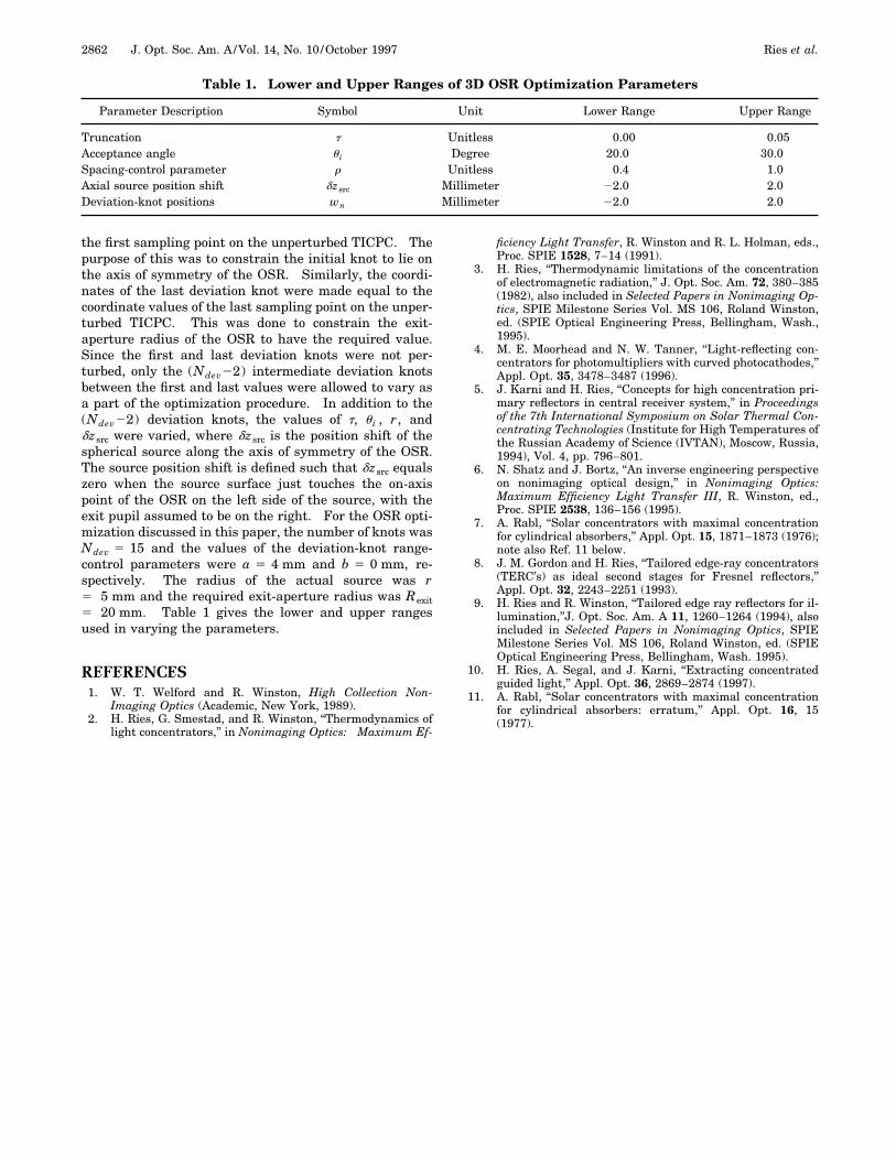
Table 1. Lower and Upper Ranges of 3D OSR Optimization Parameters
Parameter Description Symbol Unit Lower Range Upper Range
Truncation t Unitless 0.00 0.05Acceptance angle u i Degree 20.0 30.0Spacing-control parameter r Unitless 0.4 1.0Axial source position shift dzsrc Millimeter 22.0 2.0Deviation-knot positions wn Millimeter 22.0 2.0
the first sampling point on the unperturbed TICPC. Thepurpose of this was to constrain the initial knot to lie onthe axis of symmetry of the OSR. Similarly, the coordi-nates of the last deviation knot were made equal to thecoordinate values of the last sampling point on the unper-turbed TICPC. This was done to constrain the exit-aperture radius of the OSR to have the required value.Since the first and last deviation knots were not per-turbed, only the (Ndev22) intermediate deviation knotsbetween the first and last values were allowed to vary asa part of the optimization procedure. In addition to the(Ndev22) deviation knots, the values of t, u i , r, anddzsrc were varied, where dzsrc is the position shift of thespherical source along the axis of symmetry of the OSR.The source position shift is defined such that dzsrc equalszero when the source surface just touches the on-axispoint of the OSR on the left side of the source, with theexit pupil assumed to be on the right. For the OSR opti-mization discussed in this paper, the number of knots wasNdev 5 15 and the values of the deviation-knot range-control parameters were a 5 4 mm and b 5 0 mm, re-spectively. The radius of the actual source was r5 5 mm and the required exit-aperture radius was Rexit5 20 mm. Table 1 gives the lower and upper rangesused in varying the parameters.
REFERENCES1. W. T. Welford and R. Winston, High Collection Non-
Imaging Optics (Academic, New York, 1989).2. H. Ries, G. Smestad, and R. Winston, ‘‘Thermodynamics of
light concentrators,’’ in Nonimaging Optics: Maximum Ef-
ficiency Light Transfer, R. Winston and R. L. Holman, eds.,Proc. SPIE 1528, 7–14 (1991).
3. H. Ries, ‘‘Thermodynamic limitations of the concentrationof electromagnetic radiation,’’ J. Opt. Soc. Am. 72, 380–385(1982), also included in Selected Papers in Nonimaging Op-tics, SPIE Milestone Series Vol. MS 106, Roland Winston,ed. (SPIE Optical Engineering Press, Bellingham, Wash.,1995).
4. M. E. Moorhead and N. W. Tanner, ‘‘Light-reflecting con-centrators for photomultipliers with curved photocathodes,’’Appl. Opt. 35, 3478–3487 (1996).
5. J. Karni and H. Ries, ‘‘Concepts for high concentration pri-mary reflectors in central receiver system,’’ in Proceedingsof the 7th International Symposium on Solar Thermal Con-centrating Technologies (Institute for High Temperatures ofthe Russian Academy of Science (IVTAN), Moscow, Russia,1994), Vol. 4, pp. 796–801.
6. N. Shatz and J. Bortz, ‘‘An inverse engineering perspectiveon nonimaging optical design,’’ in Nonimaging Optics:Maximum Efficiency Light Transfer III, R. Winston, ed.,Proc. SPIE 2538, 136–156 (1995).
7. A. Rabl, ‘‘Solar concentrators with maximal concentrationfor cylindrical absorbers,’’ Appl. Opt. 15, 1871–1873 (1976);note also Ref. 11 below.
8. J. M. Gordon and H. Ries, ‘‘Tailored edge-ray concentrators(TERC’s) as ideal second stages for Fresnel reflectors,’’Appl. Opt. 32, 2243–2251 (1993).
9. H. Ries and R. Winston, ‘‘Tailored edge ray reflectors for il-lumination,’’J. Opt. Soc. Am. A 11, 1260–1264 (1994), alsoincluded in Selected Papers in Nonimaging Optics, SPIEMilestone Series Vol. MS 106, Roland Winston, ed. (SPIEOptical Engineering Press, Bellingham, Wash. 1995).
10. H. Ries, A. Segal, and J. Karni, ‘‘Extracting concentratedguided light,’’ Appl. Opt. 36, 2869–2874 (1997).
11. A. Rabl, ‘‘Solar concentrators with maximal concentrationfor cylindrical absorbers: erratum,’’ Appl. Opt. 16, 15(1977).