performance evaluation of network mobility over future aeronautical link-.pdf
TRANSCRIPT

Performance Evaluation of Network MobilityHandover over Future Aeronautical Data Link
Serkan Ayaz∗, Felix Hoffmann∗, Christoph Sommer†, Reinhard German† and Falko Dressler†∗Institute of Communications and Navigation, German Aerospace Center (DLR), Wessling, Germany
{serkan.ayaz,felix.hoffmann}@dlr.de†Computer Networks and Communication Systems, Dept. of Computer Science, University of Erlangen, Germany
{christoph.sommer,german,dressler}@informatik.uni-erlangen.de
Abstract—The aviation community is currently working onthe standardization of data communication systems for thefuture air traffic management. In this context, the ICAO andEUROCONTROL are working on the standardization of IP-based aeronautical telecommunications network and future radioaccess technologies, respectively. With this work, for the firsttime, we integrate L-DACS 1, which is one candidate forfuture radio access technologies, with realistic IP-based networklayer functionality and analyze the handover delay performance.We first investigate the effect of link layer retransmissions onhandover delay performance. We realized that for regions withlow signal-to-noise ratio (BER of 10−3), link layer retransmissionsimprove the total handover delay (layer 2 and 3) by about 80 %.Considering regions with high signal-to-noise ratio (BER of 10−5),the benefit of link layer retransmissions becomes negligible dueto the reduced number of packet losses. During our analysis, wenotice frequent transmissions of router advertisement messagescausing significant overhead on L-DACS 1 and propose twoapproaches in order to decrease the overhead to an acceptablerange. In the last section, we tackle the increase in handoverdelay due to a limited number of return link resource requestopportunities in congested cells.
I. INTRODUCTION
In the aeronautical domain, there are two main communica-tion services, namely Air Traffic Services (ATS) and AirlineOperations Services (AOS) [1]. ATS corresponding nodes areused to provide navigation, control, and situational awarenessservices to the aircraft, whereas AOS corresponding nodesare mainly used for business operations of airline companies.Using today’s communication technologies, these services aregenerally performed by using analogue voice communications.However, it is already known that digital data communicationutilizes the bandwidth more efficiently and overall is muchless error-prone than analogue voice communication.
For this reason, two main activities are running in parallel inorder to build a future aeronautical communications network.On the one side, the ICAO is working on the standardizationof the next generation IPv6-based Aeronautical Telecommu-nications Network (ATN/IPS) [2] and, on the other side, theEuropean EUROCONTROL and the U.S. FAA are workingon the standardization of future radio access technologies foraeronautics.
In this work, we analyze the handover performance of the L-Band Digital Aeronautical Communications System Option 1(L-DACS 1) integrated with the IPv6 network layer function-ality including Network Mobility (NEMO) support [3].
A. Related Work
Mobile IPv6 (MIPv6) and its extensions are very wellstudied protocols by the research community. Previous studiesmainly considered link technologies from the domain of con-sumer electronics. For example, a simulation study of MIPv6on IEEE 802.11b provides a performance evaluation of differ-ent smart handover extensions including link layer triggersfor MIPv6 [4]. Another work presents testbed experimentsrelated to the use of MIPv6 with IEEE 802.11g technology[5]. Similar results have been presented in [6]. Here, MIPv6has been studied in an experimental testbed using WiMAX andWi-Fi as underlying link layer technologies. In [7], NEMO isused as a base protocol in a testbed where two different 802.11interface cards are used in order to perform make-before-breakhandovers. Although having multiple interfaces from the sametechnology provides better handover delay, it is not realisticin aeronautical domain due to cost, space and weight.
In the aeronautical domain another set of link technolo-gies are considered, which mainly differ due to their datarate and cell size. Currently deployed link technologiesprovide data rates in the range of 3–30 kbit s−1 per cell.However, future radio access technologies like L-DACS 1,which this paper also focuses on, provide data rates in therange of 291–1318 kbit s−1 in the Forward Link (FL) and270–1267 kbit s−1 in the Return Link (RL) per cell dependingon selected modulation and coding scheme. Although L-DACS1 increases the data rate beyond that provided by currentaeronautical links, the link capacity is still far behind thatof consumer electronics. Another difference is the cell size,with radii in the range of 100–200 km and each cell providingservices for up to around 500 aircraft (abbreviated as “a/c” inthe rest of this paper). This means that with the lowest modu-lation and coding scheme each a/c uses less than 1 kbit s−1 onaverage. It is thus vital to decrease the network layer signalingoverhead on the wireless link without degrading the handoverdelay performance.
In our previous work, we presented an initial step towardsinvestigations of MIPv6 handover delay in an aeronautical en-vironment [8]. However, only generic link layers with certainbandwidth and delay values were considered, whereas we nowassume a realistic link layer, i.e. L-DACS 1, including anAutomatic Repeat Request (ARQ) component.
978-1-4244-5637-6/10/$26.00 ©2010 IEEE
This full text paper was peer reviewed at the direction of IEEE Communications Society subject matter experts for publication in the IEEE Globecom 2010 proceedings.

RA(6.72 ms)
Multi-Frame 1(58.32 ms)
Multi-Frame 2(58.32 ms)
Multi-Frame 3(58.32 ms)
Multi-Frame 4(58.32 ms)
Super-Frame (240 ms)
RA 1 RA 2 DC RL DataBC FL Data CC FL Data
BC(6.72 ms)
Multi-Frame 1(58.32 ms)
Multi-Frame 2(58.32 ms)
Multi-Frame 3(58.32 ms)
Multi-Frame 4(58.32 ms)
variable
variable
Fig. 1. L-DACS 1 frame structure
B. Contribution
The contribution of this paper is threefold. First, afterintroducing L-DACS 1 (Section II), we analyze the handoverperformance in an integrated L-DACS 1 access network withrealistic IPv6 network layer functionality (Section III). Tothe best of our knowledge, this integration has not yet beenanalyzed in detail, even though it is one of the most promisingcandidates for future aeronautical radio access technologies.
Secondly, as during our analysis, we noticed frequent trans-missions of router advertisement messages, which cause sig-nificant overhead on L-DACS 1, we propose two approachesto solve this problem (Sections IV-A and IV-B). We show thatthese can decrease the overhead to an acceptable range withoutdegrading handover delay performance.
Finally, we examine the handover delay increase when ana/c enters a congested cell. This is due to the limited numberof sub-slots in the RL control channel. We propose a methodto reduce the handover delay in such a case, only changingthe control channel allocation strategy (Section V).
II. L-BAND DIGITAL AERONAUTICAL COMMUNICATIONS
SYSTEM OPTION 1
EUROCONTROL and the FAA are currently consideringtwo candidate radio access technologies for the future provi-sion of ATS and AOS services in the L-band.1 These technolo-gies are referred to as L-DACS 1 and 2. Initial specificationsfor both technologies have been published by EUROCON-TROL, and it is planned that one of these two systemswill become operational around 2020. L-DACS 1 has beendesigned for the transmission of both digital voice and data.In L-DACS 1, RL and FL are separated by means of FrequencyDivision Duplex (FDD). In the RL, a combination of Orthogo-nal Frequency Division Multiple Access (OFDMA) and TimeDivision Multiple Access (TDMA) is used, whereas in theFL, Orthogonal Frequency Division Multiplexing (OFDM) isapplied. The TDMA component in the RL is selected in orderto minimize the possibility of interference with legacy systemswhich are operating in the L-band (e.g. distance measuringequipment). This is important since an L-DACS 1 transmitteroperates close to other receivers on board, so it should onlybe active for a short time, reducing these receivers’ exposureto interference.
1see http://www.eurocontrol.int/communications/
variable
fix
variable
fixvariable
fix
variable
fixFL MAP and RL MAP are both transmitted in the CC slot.
Scope of FL MAP Scope of RL MAP
Fig. 2. L-DACS 1 resource allocation structure
A. Frame Structure and Resource Allocation
The frame structure is shown in Figure 1. Time is dividedinto superframes with a duration of 240 ms. At the beginningof each superframe, a/c have the opportunity to log onto thenetwork using a Random Access Channel (RACH), whereasthe Base Station (BS) transmits general cell information inthe Broadcast Channel (BCCH). The rest of the superframeconsists of four multiframes, each with a duration of 58.32 msand consisting of both data and control frames. In the FL, theBS transmits control information, such as resource allocation,i.e. FL mapping and RL mapping, and acknowledgments onthe Common Control Channel (CCCH). In the RL, each a/c isassigned one slot per multiframe within the Dedicated ControlChannel (DCCH) for the transmission of control data. At most,52 a/c can be accommodated within the DCCH. If more a/care registered with a single BS, a/c will not receive a DCCHslot in every multiframe. Both the CCCH and DCCH are ofvariable length to allow efficient use of the wireless resources.
Before any transmission can take place, either in the RLor the FL, resources must be requested from the BS. At thebeginning of a CCCH slot, the BS considers all receivedresource requests (sent via an RSRC RQST message) since thelast CCCH slot. It allocates resources, i.e. TDMA slots andOFDMA subchannels, for the a/c, and informs the a/c via anRSRC RESP message. The exact scheduling algorithm to beused by the BS is left open by the L-DACS 1 specification. Inour implementation, we have adopted static priority queuing,i.e. requests with the highest priority are fulfilled first. Theallocation of resources is broadcast to all a/c in the CCCHslot, specifying which a/c is allowed to transmit when and onwhich subchannels. The scope of this resource allocation isshown in Figure 2.
B. Automatic Repeat Request Mechanism
L-DACS 1 supports both unacknowledged and acknowl-edged data transfer modes. Due to the rigid frame structure ofthe L-DACS 1 protocol, a sender knows when it should expectan acknowledgment for data that it has transmitted. After onemissed acknowledgment opportunity, a packet is retransmitted.After a certain number of subsequent retransmissions (inour scenarios, we considered one retransmission), the entiretransmission is aborted and the packet is discarded at thetransmitter. Note that the entire process of resource requestand allocation must again be performed before the lost packetcan be retransmitted.
978-1-4244-5637-6/10/$26.00 ©2010 IEEE
This full text paper was peer reviewed at the direction of IEEE Communications Society subject matter experts for publication in the IEEE Globecom 2010 proceedings.

C. Handover Types
Two different types of handover are foreseen by the L-DACS 1 specification. In both handover types, the BS pollsthe a/c to provide power reports of their received signalstrength. Polling of neighboring cells’ received signal strengthis requested by transmitting neighboring cell frequencies in theBroadcast Control Information (BCI) message. In the upcom-ing BCI slot, the a/c switches to the next BS frequency andmeasures the received power by listening to a BCI messagefrom this BS. It then sends a POW REP power report messageto the current BS. If the adjacent cell’s received power levelis higher than that of the current cell, the current BS triggersa HO COM handover message to this cell.
In the case of a type 1 handover, the a/c simply confirmsthe handover, sends a CELL EXIT message to the currentBS, and switches to the channel of the next BS, where itregisters via the new station’s RACH by sending a CELL RQST
message. If no collision has occurred on the RACH, the BSwill respond with a CELL RESP on the CCCH and assigna subscriber access code and a DCCH slot to the a/c. Inthe case of a collision on the RACH, the aircraft does notreceive this response and will perform an exponential backoff,attempting to access the RACH again later.2 In this paper, weonly consider type 1 handover since it does not require anysignaling between BSs and is more suitable for inter-accessnetwork handovers. The details of type 2 handover can befound in L-DACS 1 specification.
D. Handling of Control Message Losses
In this section, we will summarize how the system reactsif one of the control messages is lost during the transmission(the names of message types in small caps are taken from theL-DACS 1 specification).
An a/c sends a KEEP ALIVE in order to inform the BS thatit is still connected. After a certain amount of KEEP ALIVE
messages (in our simulations we used 20) is not received bythe BS, it de-registers the a/c from its connected a/c list. If aPOW REP is lost, the BS continues to use the last measuredvalue if it is available. If no information is available (which isthe case during the first scanning request of the neighboringcell), the BS should wait for the next POW REP message inorder to decide whether a handover is needed. If a HO COM
is lost, the BS sends another one in the upcoming CCCH slot.If a CELL RQST is lost, the a/c sends another CELL RQST
in the upcoming random access slot, which is at the beginningof the next superframe (i.e., at 240 ms). If a CELL RESP
is lost, the a/c again sends another CELL RQST and thuscauses another CELL RESP to be sent from the BS. If aCELL EXIT is lost, the BS will consequently not receive anymore KEEP ALIVE messages from that a/c, so eventually thesystem will react as outlined there.
If an RSRC RQST is lost, the a/c sends another request in theupcoming DCCH slot. If an RSRC RESP is lost, the allocatedslot information is not known by the a/c and the associated
2We did not investigate this effect due to its low probability of occurrence
TABLE ILAYER 3 PARAMETERS RELATED TO HANDOVER
Parameter Value
MIN RTR ADV INTERVAL 0.03 sMAX RTR ADV INTERVAL 0.07 s
IPv6 DEFAULT DUPADDRDETECTTRANSMITS 1IPv6 DEFAULT RETRANS TIMER 1 s
IPv6 MAX RTR SOLICITATION DELAY 1 sMIPv6 INITIAL BINDACK TIMEOUT 1 s
MIPv6 INITIAL BINDACK TIMEOUT FIRST 1.5 sMIPv6 MAX BINDACK TIMEOUT 32 s
packets are not received by the a/c. If a BCI carrying ascanning request of the next BS is lost, the a/c will not startscanning of the next BS. In addition, if an a/c does not receiveany BCI within a certain time (in our simulations we used4 s), it will assume the connection was lost and switch to ascanning state. Finally, if a SLOT DESC is lost, the a/c cannotidentify the beginning of the FL data part. Moreover, no RLresource requests can be made for the upcoming multiframe.In general, the a/c needs to wait for the next SLOT DESC inorder to receive and send data.
III. PERFORMANCE ASSESSMENT
The aeronautical communications panel of the ICAO hasrecently recommended IPv6-based ATN/IPS [2]. In this spec-ification, MIPv6 [9] is considered as a basic mobility man-agement protocol and NEMO [3] is mentioned as an optionalprotocol extension of MIPv6. It is already known that sinceMIPv6 supports only host mobility, its mobility signalingoverhead becomes problematic if we assume a/c with multiplemobile nodes on board. For this reason, we consider NEMOas a mobility management protocol in this paper.
In order to assess the performance of L-DACS 1 integratedwith main network layer functionality, we modeled the pro-tocols within the OMNeT++ simulator [10]. As mentionedwe implemented L-DACS 1 offering type 1 handovers andintegrate it with the NEMO protocol at the network layer inorder to provide seamless mobility to the a/c. Table I shows theparameters used at the network layer. The first five parametersare related to the neighbor discovery protocol where the firsttwo values define the Router Advertisement (RA) intervalsent by the Access Router (AR) [9], [11] and the next threeparameters are related to the Duplicate Address Detection(DAD) and Multicast Listener Discovery (MLD) procedures.The last three parameters are specific to the MIPv6/NEMOprotocols and related to home registration.
In our simulations, when the a/c receives a new RA messagewith different prefix information, it assumes the RA is comingfrom a different access network – however, in reality differentprefixes can be advertised by the same access network. Asfuture work, we plan to use advanced movement detectionmethods as described in [12]–[14].
In addition, we also assume a certain Bit Error Rate (BER)in our simulations (BER = 10−3 and BER = 10−5) in orderto reflect packet loss due to channel errors.
978-1-4244-5637-6/10/$26.00 ©2010 IEEE
This full text paper was peer reviewed at the direction of IEEE Communications Society subject matter experts for publication in the IEEE Globecom 2010 proceedings.

BS - A1 BS - A2 BS – B1
MR: Mobile RouterBS: Base StationAR: Access Router
AR – B1
L-DACS 1 Home
Domain
Inter-AN with layer 3 handover
MR MR
MaastrichtCN
5 ms 5 ms 5 ms
15 ms15 ms
BR15 ms
Core Network CN Subnetwork
L-DACS 1 ForeignDomain
BR: Backbone RouterHA: Home AgentCN: Correspondent Node
HA
Fig. 3. Example topology for the European scenario
A. Considered topology
The main topological considerations for the ATN/IPS areprovided in [15]. In our analysis, the European scenarioshown in Figure 3 is considered, where the a/c are commu-nicating with an ATS controller located in Maastricht. Ana/c starts communication when it is located in the homedomain, performs handover during communication, and movesto the foreign domain. This is a kind of inter-access networkhandover so that the aircraft should complete layer 2 andlayer 3 handover procedures in order to continue communi-cation. Within the ground network, the fixed delay valuesshown in the figure were used. In the aeronautical domain, thecell radius is generally between 100 km and 200 km and thecell overlapping regions are quite large so that the handoverperformance does not degrade due to high speed of an a/c.
B. Handover Performance with ARQ Mechanism
In this section, we analyze the benefit of the ARQ mecha-nism for handover delay performance under different channelconditions.
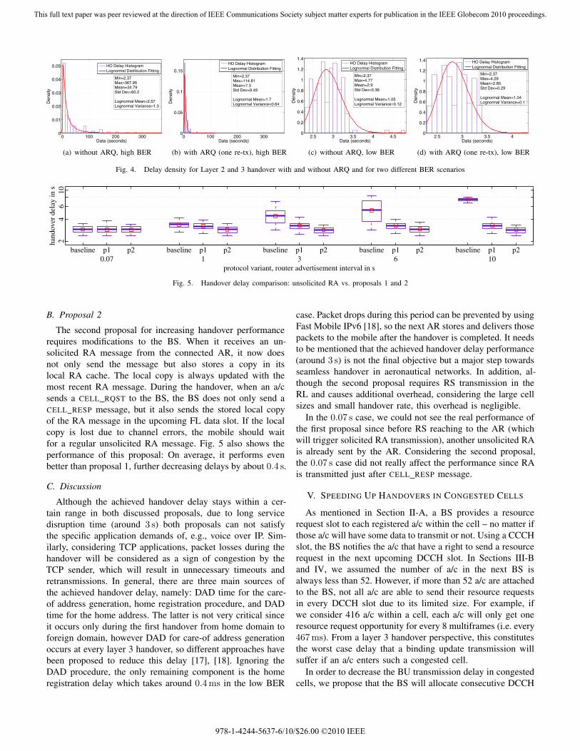
1) High BER Scenario: In this first scenario, we assumea BER of 10−3. We calculate the corresponding packet errorrate as PER = 1 − (1 − BER)n, with n denoting the packetlength. Table II shows the average delay values for an a/cperforming layer 2 and layer 3 handovers. These values aretaken from 25 simulation runs where each run simulates 20a/c handover instances. In particular, Table II shows the delayvalues of each step contributing to the total handover delay. Ascan be seen the main difference between both scenarios is thedelay incurred by home registration, i.e. the Binding Update(BU)–Binding Acknowledgment (BA) exchange. In the casewhere ARQ is not used, due to more frequent loss of eitherBU or BA messages the handover takes much longer. Use ofARQ with single retransmission can thus improve the totalhandover delay performance by around 80 %. Detailed plotsof the delay distribution can be seen in Figs. 4(a) and 4(b).
TABLE IIAVERAGE HANDOVER DELAY VALUES FOR LAYERS 2 AND 3
no ARQ one re-tx
L2 Handover Completion Time in s 0.09 0.09RA Reception Time in s 0.03 0.027
MLD-DAD Completion Time in s 1.5 1.5Home Registration Time in s 33.17 5.68
Total Time in s 34.8 7.3
2) Low BER Scenario: In the second scenario, the samesimulation settings have been used for BER = 10−5. Due tothe low BER, the system experiences less packet loss and thebenefit of ARQ becomes negligible. Again, detailed plots ofthe delay distribution can be seen in Figs. 4(c) and 4(d). Theaverage delay stays around 2.85–2.9 s in both cases.
IV. REDUCING ROUTER ADVERTISEMENT OVERHEAD
MIPv6 specifies RA transmission intervals of 30–70 ms inorder to minimize the handover delay. If a RA message ofaround 100 B is sent at the MIN RTR ADV INTERVAL, i.e.every 30 ms, the overhead corresponds to around 9 % of theL-DACS 1 FL capacity with lowest modulation and codingscheme. This could be problematic in high density cells wherethere could be around 500 a/c. For this reason, we propose twomethods in order to decrease the unsolicited RA overheadwithout degrading the handover delay performance. In thissection, we used the same simulation settings of low BERscenario without considering ARQ mechanism.
A. Proposal 1
In our first proposal, we utilize the Link Down and LinkUp event services of IEEE 802.21 [16] to improve handoverperformance. When the a/c sends a CELL EXIT message tothe current BS, L-DACS 1 in the a/c triggers a Link Downevent. When the new link becomes available after the layer 2handover is completed, a Link Up event is triggered by L-DACS 1. Upon reception of the Link Up event, the networklayer transmits a Router Solicitation (RS) and waits for theRA message. According to [11], a host should transmit upto MAX RTR SOLICITATIONS RS messages, at intervalsof at least RTR SOLICITATION INTERVAL seconds. In ourcase, when the network layer receives a Link Up event, itsends an RS immediately, ignoring this delay, in order to fasterperform the handover. However, if the first RS or the respectivesolicited RA message is lost due to channel errors, the a/cdelays the second RS according to the standard.
Fig. 5 shows the resulting performance compared withthe regular case where only unsolicited RA messages aretransmitted. Here, different unsolicited RA intervals between0.07 s and 10 s are considered. As can be seen, the handoverdelay performance becomes independent of the unsolicited RAtransmission interval when the mobile sends the RS message.If we consider unsolicited RAs with 10 s intervals, the over-head decreases significantly to a level of few hundred bit s−1.
978-1-4244-5637-6/10/$26.00 ©2010 IEEE
This full text paper was peer reviewed at the direction of IEEE Communications Society subject matter experts for publication in the IEEE Globecom 2010 proceedings.
0 100 200 3000
0.01
0.02
0.03
0.04
0.05
Data (seconds)
Den
sity
HO Delay HistogramLognormal Distribution Fitting
Min=2.37Max=367.95Mean=34.79Std Dev=60.2
Lognormal Mean=2.57Lognormal Variance=1.3
(a) without ARQ, high BER
0 100 200 3000
0.05
0.1
0.15
Data (seconds)
Den
sity
HO Delay HistogramLognormal Distribution Fitting
Min=2.37Max=114.81Mean=7.3Std Dev=9.49
Lognormal Mean=1.7Lognormal Variance=0.64
(b) with ARQ (one re-tx), high BER
2.5 3 3.5 4 4.50
0.2
0.4
0.6
0.8
1
1.2
1.4
Data (seconds)
Den
sity
HO Delay HistogramLognormal Distribution Fitting
Min=2.37Max=4.77Mean=2.9Std Dev=0.36
Lognormal Mean=1.05Lognormal Variance=0.12
(c) without ARQ, low BER
2.5 3 3.5 40
0.2
0.4
0.6
0.8
1
1.2
1.4
Data (seconds)
Den
sity
HO Delay HistogramLognormal Distribution Fitting
Min=2.37Max=4.29Mean=2.85Std Dev=0.29
Lognormal Mean=1.04Lognormal Variance=0.1
(d) with ARQ (one re-tx), low BER
Fig. 4. Delay density for Layer 2 and 3 handover with and without ARQ and for two different BER scenarios
protocol variant, router advertisement interval in s
hand
over
del
ay in
s
baseline p1 p2 baseline p1 p2 baseline p1 p2 baseline p1 p2 baseline p1 p20.07 1 3 6 10
24
610
Fig. 5. Handover delay comparison: unsolicited RA vs. proposals 1 and 2
B. Proposal 2
The second proposal for increasing handover performancerequires modifications to the BS. When it receives an un-solicited RA message from the connected AR, it now doesnot only send the message but also stores a copy in itslocal RA cache. The local copy is always updated with themost recent RA message. During the handover, when an a/csends a CELL RQST to the BS, the BS does not only send aCELL RESP message, but it also sends the stored local copyof the RA message in the upcoming FL data slot. If the localcopy is lost due to channel errors, the mobile should waitfor a regular unsolicited RA message. Fig. 5 also shows theperformance of this proposal: On average, it performs evenbetter than proposal 1, further decreasing delays by about 0.4 s.
C. Discussion
Although the achieved handover delay stays within a cer-tain range in both discussed proposals, due to long servicedisruption time (around 3 s) both proposals can not satisfythe specific application demands of, e.g., voice over IP. Sim-ilarly, considering TCP applications, packet losses during thehandover will be considered as a sign of congestion by theTCP sender, which will result in unnecessary timeouts andretransmissions. In general, there are three main sources ofthe achieved handover delay, namely: DAD time for the care-of address generation, home registration procedure, and DADtime for the home address. The latter is not very critical sinceit occurs only during the first handover from home domain toforeign domain, however DAD for care-of address generationoccurs at every layer 3 handover, so different approaches havebeen proposed to reduce this delay [17], [18]. Ignoring theDAD procedure, the only remaining component is the homeregistration delay which takes around 0.4 ms in the low BER
case. Packet drops during this period can be prevented by usingFast Mobile IPv6 [18], so the next AR stores and delivers thosepackets to the mobile after the handover is completed. It needsto be mentioned that the achieved handover delay performance(around 3 s) is not the final objective but a major step towardsseamless handover in aeronautical networks. In addition, al-though the second proposal requires RS transmission in theRL and causes additional overhead, considering the large cellsizes and small handover rate, this overhead is negligible.
In the 0.07 s case, we could not see the real performance ofthe first proposal since before RS reaching to the AR (whichwill trigger solicited RA transmission), another unsolicited RAis already sent by the AR. Considering the second proposal,the 0.07 s case did not really affect the performance since RAis transmitted just after CELL RESP message.
V. SPEEDING UP HANDOVERS IN CONGESTED CELLS
As mentioned in Section II-A, a BS provides a resourcerequest slot to each registered a/c within the cell – no matter ifthose a/c will have some data to transmit or not. Using a CCCHslot, the BS notifies the a/c that have a right to send a resourcerequest in the next upcoming DCCH slot. In Sections III-Band IV, we assumed the number of a/c in the next BS isalways less than 52. However, if more than 52 a/c are attachedto the BS, not all a/c are able to send their resource requestsin every DCCH slot due to its limited size. For example, ifwe consider 416 a/c within a cell, each a/c will only get oneresource request opportunity for every 8 multiframes (i.e. every467 ms). From a layer 3 handover perspective, this constitutesthe worst case delay that a binding update transmission willsuffer if an a/c enters such a congested cell.
In order to decrease the BU transmission delay in congestedcells, we propose that the BS will allocate consecutive DCCH
978-1-4244-5637-6/10/$26.00 ©2010 IEEE
This full text paper was peer reviewed at the direction of IEEE Communications Society subject matter experts for publication in the IEEE Globecom 2010 proceedings.

protocol variant, number of a/c in the next BS
hand
over
del
ay in
s
b p3 b p3 b p3 b p3 b p3 b p31 100 200 300 400 500
01
23
45
Fig. 6. Handover delay comparison: baseline vs. proposal 3
slots to the newly attached aircraft for certain duration. In oursimulations we used 16 superframes (around 3.8 s) since mostof the handovers are completed in less than 4 s for low BERcases as mentioned in Section III-B2. By doing this, the BSallows the aircraft to send its resource request immediatelywhen the BU message arrives at the L-DACS 1 queue. Fig. 6shows the handover delay values for different numbers of a/cin the next cell. As shown in the figure, with our proposal,the handover delay stays constant no matter how many a/care attached to the cell. If 500 a/c are attached to the BS ourproposal can thus reduce handover delay by around 0.7 s.
Our proposal requires modification to the CCCH slot struc-ture which affects the DCCH slot allocations so that a BS iscapable of assigning a DCCH slot to a desired a/c on demandwithin the cell. In the regular case, a BS assigns a/c to eachDCCH slot based on the ordered subscriber access code.
It is good to mention that aircraft performing handover usethe assigned consecutive resource request opportunities onlyfor the transmission of the mobility signaling, not for userdata. This is due to fact that RL capacity should be used byall users in equal amounts. Resource requests for the user datawill be sent only in the regular dedicated DC slots as definedin the L-DACS 1 specification.
In addition, if we consider one a/c performing handoverfor certain duration, during this time, one less a/c will gainaccess to the DCCH slot. This is not very critical since thata/c will only be affected at most one multiframe duration, i.e.58.32 ms.
VI. CONCLUSION
In this paper, we analyzed the applicability of Mobile IPv6in the context of ATN/IPS. We took into account all ofthe specific requirements of layer 2, i.e. of L-DACS 1. Inparticular, we investigated the benefit of ARQ on the handoverdelay performance. Based on our results, we can point outthat in high BER scenarios the use of ARQ is indispensablein order to perform home registration within acceptable time.In low BER scenarios, on the other hand, the use of ARQwill not further improve handover delays. In that case, averagehandover delay values stay around 2.8–2.9 s.
Based on these findings and the observation that signalingoverhead due to frequent transmission of RA messages hasa significant impact on L-DACS 1 capacity in the FL, wepropose two modifications to reduce this overhead. Our firstproposal uses the functionality defined by the IEEE 802.21
standard with additional logic at the network layer. Althoughwe have implemented some basic primitives of IEEE 802.21standard in the first proposal, further analysis is required inorder to implement the whole 802.21 stack for aeronauticalenvironment. Our second proposal extends L-DACS 1 func-tionality by sending an RA message in the FL data slotfollowing CELL RESP message so that an a/c will not onlyenter a cell but also receive an RA message and performaddress configuration. Compared to the first proposal, thisprovides much better performance (about 0.4 s).
In the last section, we proposed a new method so that theBS can assign DCCH slot to connected a/c dynamically. Byusing this method, handover delay is reduced by 0.7 s in theworst case (i.e. 500 connected a/c).
REFERENCES
[1] W. M. Eddy, W. Ivancic, and T. Davis, “NEMO Route OptimizationRequirements for Operational Use in Aeronautics and Space ExplorationMobile Networks,” IETF, RFC 5522, October 2009.
[2] “Manual for the ATN using IPS Standards and Protocols,” ICAO, Tech.Rep. Doc 9896-AN/469, 2009.
[3] V. Devarapalli, R. Wakikawa, A. Petrescu, and P. Thubert, “NetworkMobility (NEMO) Basic Support Protocol,” IETF, RFC 3963, January2005.
[4] J. Lai, Y. A. Sekercioglu, N. Jordan, and A. Pitsillides, “PerformanceEvaluation of Mobile IPv6 Handover Extensions in an IEEE 802.11bWireless Network Environment,” in 11th IEEE Symposium on Computersand Communications (ISCC 2006). Sardinia, Italy: IEEE, June 2006,pp. 161–166.
[5] G. Xie, J. Chen, H. Zheng, J. Yang, and Y. Zhang, “Handover Latencyof MIPv6 Implementation in Linux,” in IEEE Global Telecommunica-tions Conference (IEEE GLOBECOM 2007). Washington, DC: IEEE,November 2007, pp. 1780–1785.
[6] J. Pinola and K. Pentikousis, “IPTV over WiMAX with MIPv6 Han-dovers,” in 69th IEEE Vehicular Technology Conference (VTC2009-Spring). Barcelona, Spain: IEEE, April 2009, pp. 1–5.
[7] H. Petander, E. Perera, and K.-C. L. A. Seneviratne, “Measuring andImproving the Performance of Network Mobility Management in IPv6Networks,” IEEE Journal on Selected Areas in Communications (JSAC),vol. 24, no. 9, pp. 1671–1681, 2006.
[8] C. Bauer and S. Ayaz, “A Thorough Investigation of Mobile IPv6for the Aeronautical Environment,” in 68th IEEE Vehicular TechnologyConference (VTC2008-Fall). Calgary, BC, Canada: IEEE, September2008, pp. 1–5.
[9] D. B. Johnson, C. E. Perkins, and J. Arkko, “Mobility Support in IPv6,”IETF, RFC 5477, June 2004.
[10] A. Varga, “The OMNeT++ Discrete Event Simulation System,” in Euro-pean Simulation Multiconference (ESM 2001), Prague, Czech Republic,June 2001.
[11] T. Narten, E. Nordmark, W. A. Simpson, and H. Soliman, “NeighborDiscovery for IP version 6 (IPv6),” IETF, RFC 4861, September 2007.
[12] C. Vogt, “A Comprehensive Delay Analysis for Reactive and ProactiveHandoffs with Mobile IPv6 Route Optimization,” TU Karlsruhe, Instituteof Telematics, Technical Report TM-2006-1, January 2006.
[13] N. A. Fikouras and C. Gorg, “Performance comparison of hinted- andadvertisement-based movement detection methods for mobile IP hand-offs,” Elsevier Computer Networks, vol. 37, no. 1, pp. 55–62, 2001.
[14] Y.-G. Hong, M.-K. Shin, and H.-J. Kim, “Fast Handover for Mobile IPv6using Access Router Based Movement Detection and CoA Configura-tion,” in 59th IEEE Vehicular Technology Conference (VTC2004-Spring).Milan, Italy: IEEE, May 2004, pp. 2442–2446.
[15] C. Bauer and S. Ayaz, “ATN Topology Considerations for AeronauticalNEMO RO,” IETF, Internet-Draft (work in progress) draft-bauer-mext-aero-topology-01.txt, September 2009.
[16] “Standard for Local and Metropolitan Area Networks: Media Indepen-dent Handover Services,” IEEE, IEEE Standard 802.21, 2008.
[17] N. Moore, “Optimistic Duplicate Address Detection (DAD) for IPv6,”IETF, RFC 4429, April 2006.
[18] R. Koodli, “Mobile IPv6 Fast Handovers,” IETF, RFC 5268, June 2008.
978-1-4244-5637-6/10/$26.00 ©2010 IEEE
This full text paper was peer reviewed at the direction of IEEE Communications Society subject matter experts for publication in the IEEE Globecom 2010 proceedings.