performance characteristics of single effect lithium
TRANSCRIPT

PERFORMANCE CHARACTERISTICS OF SINGLE EFFECT LITHIUM
BROMIDE/ WATER ABSORPTION CHILLER FOR SMALL DATA
CENTERS
by
ABHISHEK ARUN BABU MYSORE
Presented to the Faculty of the Graduate School of
The University of Texas at Arlington in Partial Fulfillment
of the Requirements
for the Degree of
MASTER OF SCIENCE IN MECHANICAL ENGINEERING
THE UNIVERSITY OF TEXAS AT ARLINGTON
August 2015

ii
Copyright © by Abhishek Arun Babu Mysore 2015
All Rights Reserved

iii
Acknowledgements
I would like to thank my supervising professor Dr. Dereje Agonafer for
his immense support throughout my thesis. His guidance and valuable suggestions
helped me in my presentation skills. Also I would like to thank him for giving me
an opportunity to attend conferences and seminars.
I am grateful to Dr. Abdolhossein Haji-Sheikh and Dr. Ratan Kumar for
being my committee members and their inputs on my thesis work.
I am thankful to Ibraheem Sheerah for introducing me to the topic of solar
absorption chiller technology and EMNSPC lab members mainly Betsegaw
Gebrehiwot for his valuable suggestions that helped me in my research work.
Many thanks to the mechanical and aerospace engineering staff mainly
Ms. Sally Thompson and Ms. Debi Barton for being supportive throughout my
Master’s Program.
Also I would like to thank my friend Meghana Anoop for helping me
create a webpage corresponding to my research work.
My special thanks to my parents Dr. Arun Babu and Sharada A and my
sister Amritha for always being there encouraging me and without whom this
would have been difficult. I thank them for providing an opportunity for pursuing
my goals.
July 23, 2015

iv
Abstract
PERFORMANCE CHARACTERISTICS OF SINGLE STAGE LITHIUM
BROMIDE/ WATER ABSORPTION CHILLER FOR MEDIUM DATA
CENTERS
ABHISHEK ARUN BABU MYSORE, M.S.
The University of Texas at Arlington, 2015
Supervising Professor: Dereje Agonafer
A medium data center consists of servers performing operations such as
file sharing, collaboration and email. There are a large number of small and
medium data centers across the world which consume more energy and are less
efficient when compared to large data center facilities of companies such as
GOOGLE, APPLE and FACEBOOK. Such companies are making their data
center facilities more environmental friendly by employing renewable energy
solutions such as wind and solar to power the data center or in data center cooling.
This not only reduces the carbon footprint significantly but also decreases the
costs incurred over a period of time.
Cooling of data center play a vital role in proper functioning of the
servers. It is found that cooling consumes about 50% of the total power consumed
by the data center. Traditional method of cooling includes the use of mechanical
v
compression chillers which consume lot of power and is not desirable. In order to
eliminate the use of mechanical compressor chillers renewable energy resources
such as solar and wind should be employed. One such technology is solar thermal
cooling by means of absorption chiller which is powered by solar energy. The
absorption chiller unit can be coupled with either flat plate or evacuated tube
collectors in order to achieve the required inlet temperature for the generator of
the absorption chiller unit. In this study a modular data center is considered
having a cooling load requirement of 23kw. The performance characteristics of a
single stage Lithium Bromide/ water refrigeration is presented in this study
considering the cooling load of 23kw. Performance characteristics of each of the 4
heat exchangers within the unit is discussed which helps in customizing the unit
according to the users’ specific needs. This analysis helps in studying the
importance of different properties such as the effect of inlet temperatures of hot
water for generator, inlet temperatures of cooling water for absorber and
condenser and outlet chilled water temperatures of the evaporator.

vi
Table of Contents
Acknowledgements ................................................................................................ iii
Abstract .................................................................................................................. iv
List of Illustrations ............................................................................................... viii
List of Tables .......................................................................................................... x
Chapter 1 INTRODUCTION .................................................................................. 1
Chapter 2 LITERATURE REVIEW ....................................................................... 3
2.1 Data Center Classification ............................................................................ 3
2.2 Data Center Cooling Methods ...................................................................... 5
2.3 Green Data Center ........................................................................................ 6
2.4 Solar Energy Overview ................................................................................. 9
Chapter 3 ABSORPTION REFRIGERATION REVIEW ................................... 16
3.1 Absorption Refrigeration ............................................................................ 16
3.2 Solar powered absorption chiller ................................................................ 16
3.3 Vacuum tube solar panels ........................................................................... 19
3.4 Difference between vapor compression and absorption
refrigeration ...................................................................................................... 23
3.5 Literature Review ....................................................................................... 24
Chapter 4 PERFORMANCE CHARACTERISTICS ........................................... 25
4.1 Input Parameters and procedures ................................................................ 25
4.2 Tabulated Results ........................................................................................ 26

vii
4.3 Graphical Results ........................................................................................ 27
Chapter 5 GASKETED PLATE HEAT EXCHANGER ...................................... 31
Chapter 6 STEPWISE PERFORMANCE & THERMAL ANALYSIS
OF ABSORPTION CHILLER COMPONENTS ................................................. 34
6.1 Evaporator Performance and Thermal Analysis ......................................... 34
6.2 Condenser Performance and Thermal Analysis .......................................... 37
6.3 Generator Performance and Thermal Analysis ........................................... 40
6.4 Absorber Performance and Thermal Analysis ............................................ 43
Chapter 7 PERFORMANCE CHARACTERISTICS
CALCULATIONS WEBPAGE............................................................................ 46
Chapter 8 CONCLUSION .................................................................................... 48
Appendix A THERMODYNAMIC EQUATIONS FOR
PERFORMANCE CHARACTERISTICS OF SINGLE EFFECT
LITHIUM BROMIDE/WATER ABSORPTION CHILLER ............................... 50
Appendix B EQUATIONS FOR PERFORMANCE ANALYSIS AND
THERMAL ANALYSIS OF PLATE HEAT EXCHANGERS ........................... 53
References ............................................................................................................. 56
Biographical Information ...................................................................................... 60

viii
List of Illustrations
Figure 1.1 Typical Data Center Energy Consumption............................................ 1
Figure 2.1 Datacenter Classification ....................................................................... 3
Figure 2.2 Raised floor data center with cold aisle and hot aisle configuration ..... 6
Figure 2.3 Google's Hamina Data Center cooled by sea water .............................. 7
Figure 2.4 Solar cells, panels and arrays................................................................. 9
Figure 2.5 Concentrated Photovoltaic (CPV) system ........................................... 10
Figure 2.6 Concentrated Solar Power Parabolic Trough ...................................... 11
Figure 2.7 Tower Systems .................................................................................... 12
Figure 2.8 Dish system ......................................................................................... 13
Figure 2.9 Linear Fresnel Reflector ...................................................................... 14
Figure 2.10 Solar Array ........................................................................................ 15
Figure 3.1 Absorption Chiller Schematic ............................................................. 18
Figure 3.2 Evacuated tube solar panels ................................................................. 20
Figure 3.3 Evacuated Tube ................................................................................... 21
Figure 3.4 Heat Pipe ............................................................................................. 22
Figure 3.5 Vapor Absorption system .................................................................... 23
Figure 3.6 Vapor Compression System ................................................................ 24
Figure 4.1 Effect of Condenser Temperature values on COP .............................. 27
Figure 4.2 Effect of Absorber Temperature values on COP ................................. 28
Figure 4.3 Effect of Evaporator Temperature values on COP .............................. 29

ix
Figure 4.4 Effect of Generator Temperature values on COP ................................ 30
Figure 5.1 Types of configuration in PHE ............................................................ 32
Figure 5.2 Alfa Laval Plate Heat Exchanger Block Diagram ............................... 33
Figure 6.1 Alfa Laval Brazed Heat Exchanger AC30EQ/ACH30EQ .................. 34
Figure 6.2 Alfa Laval Brazed Plate Heat Exchanger AC 30/ACH 30 Product
Specifications ........................................................................................................ 35
Figure 6.3 Alfa Laval Brazed Plate Heat Exchanger CB 30/CBH 30 .................. 37
Figure 6.4 Alfa Laval Brazed Plate Heat Exchanger CB 30/CBH 30 Product
Specifications ........................................................................................................ 38
Figure 6.5 Alfa Laval Brazed Plate Heat Exchanger CB 76/CBH 76 .................. 40
Figure 6.6 Alfa Laval Brazed Plate Heat Exchanger CB 76/CBH 76 Product
Specifications ........................................................................................................ 41
Figure 6.7 Alfa Laval Brazed Plate Heat Exchanger CB 30/CBH 30 .................. 43
Figure 7.1 Performance Characteristics Webpage calculations ............................ 46
Figure 7.2 Performance Characteristics calculated values ................................... 47
x
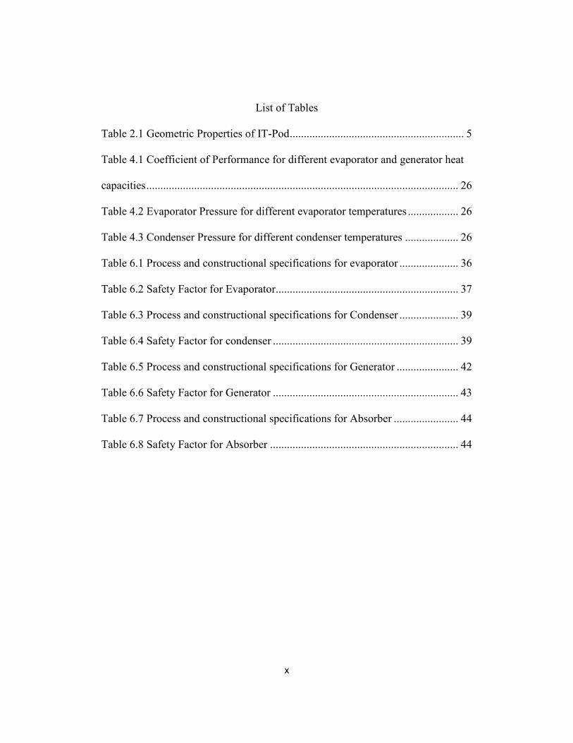
List of Tables
Table 2.1 Geometric Properties of IT-Pod .............................................................. 5
Table 4.1 Coefficient of Performance for different evaporator and generator heat
capacities ............................................................................................................... 26
Table 4.2 Evaporator Pressure for different evaporator temperatures .................. 26
Table 4.3 Condenser Pressure for different condenser temperatures ................... 26
Table 6.1 Process and constructional specifications for evaporator ..................... 36
Table 6.2 Safety Factor for Evaporator................................................................. 37
Table 6.3 Process and constructional specifications for Condenser ..................... 39
Table 6.4 Safety Factor for condenser .................................................................. 39
Table 6.5 Process and constructional specifications for Generator ...................... 42
Table 6.6 Safety Factor for Generator .................................................................. 43
Table 6.7 Process and constructional specifications for Absorber ....................... 44
Table 6.8 Safety Factor for Absorber ................................................................... 44

1
Chapter 1
INTRODUCTION
A data center is a facility which houses servers ranging from few hundred
to thousand performing critical operations of a company. It is also called as the
brain of the organization. These servers perform operations such as file sharing,
email, storage, collaboration. The servers generate a large amount of heat which
needs to be removed for proper functioning of the equipment. Data centers
consume a lot of power. Studies show that cooling equipment’s consume most of
the total power.
Figure 1.1 Typical Data Center Energy Consumption
To reduce the power consumed and to make it environmental friendly
renewable energy such as solar is used. In this study solar thermal cooling for a
modular data center is discussed and the performance parameters are determined.
2
In chapter 2 classifications of data centers based on size, data center
cooling methods, solar technology overview and literature review
Chapter 3 discusses absorption technology, overview, and advantages of
absorption chillers over vapor compression chillers.
In chapter 4 performance characteristics of a single effect lithium bromide/
water absorption chiller is evaluated for the modular data center having a cooling
load of 23k.w. Thermodynamic equations are used in calculating the respective
properties. Graphs are plotted between COP and the temperatures of the
generator, condenser, evaporator and absorber. The analysis is done using
Microsoft Excel.
In chapter 5 the performance analysis for the evaporator of the Absorption
refrigeration unit is presented by considering the manufacturers product details.
The thermodynamic equations are used to calculate the geometric properties of
the heat exchanger and to do a heat transfer analysis.
In chapter 6 the performance analysis for the condenser of the Absorption
refrigeration unit is presented by considering the manufacturers product details.
The thermodynamic equations are used to calculate the geometric properties of
the heat exchanger and to do a heat transfer analysis.

3
Chapter 2
LITERATURE REVIEW
2.1 Data Center Classification
Data centers are classified based on business needs and availability as
follows:
1. Tier I
2. Tier II
3. Tier III
4. Tier IV
Figure 2.1 Datacenter Classification
Modular data centers fall in the category of Tier I data center. A modular data
center is the one with a container which is pre-fabricated that can be shipped and
4
deployed anywhere. Some of the advantages of modular data center are listed
below:
1. Speed of deployment – It can be quickly ordered and delivered to the data
center site.
2. Agility – It has the capability of meeting the needs of the organization by
providing services and are hence built closely to the organization business
and infrastructure.
3. Mobility – It can be delivered where ever needed. The parts can be
delivered separately and are assembled together. It helps in recovery
situations where a data center needs to be setup immediately.
4. Scalability – It can easily match the demand quickly and the only changes
required will be that of the infrastructure at the site.
5. Efficiency – It has a higher efficiency because of the engineered products
of the data center.
6. Density – The space in a modular data center is used effectively and it has
a higher density when compared to a regular data center.
The modular data center (IT POD) considered in this study consists of 120 HP
SE1102 servers with cooling load requirement of 23kw.Four cabinets with servers
are placed in a cold aisle/hot aisle configuration. The geometric properties of the
modular data center are:

5
Table 2.1 Geometric Properties of IT-Pod
SL No Name Value Units
1. Length 28 ft
2. Width 12 ft
3. Height 10 ft
2.2 Data Center Cooling Methods
The heat generated by the servers within the data center needs to be
dissipated for proper functioning of the components. Improper cooling results in
failure of components.
There are several data center cooling methods some of which are listed below:
CRAC (computer room air conditioning): CRAC units are used in cooling of data
centers by introducing cold air through the raised floors of the data center by
perforated tiles. The servers are usually placed in a hot aisle and cold aisle
configuration. The warm air is rejected back to the CRAC units.
Free Cooling: cooling towers are used to cool the servers by removing the coolant
heat from the heat exchanger. This is a more energy efficient solution compared
to the use of chiller.
Airflow: In order to increase the airflow to the servers the number of perforated
tiles can be varied. In order for good circulation the cold air from the perforated
tiles should match the horizontal air from the servers.

6
In Rack Cooling: It acts like an air to water heat exchanger within the racks which
allows the warm air from the servers to pass over the tubes containing cold water.
This helps in lowering the load on the CRAC units.
Container Data Centers: This houses the servers and the cooling units within a
shipping container. It also includes the power system. It can handle high power
densities.
Figure 2.2 Raised floor data center with cold aisle and hot aisle configuration
2.3 Green Data Center
Green Data Centers are powered entirely or partially by renewable energy
sources such as solar energy. Their dependence on non-renewable sources is
minimum. They are designed in such a way that the lighting, storage, mechanical,

7
electrical and computer systems are functioning at maximum efficiency. Due to
use of renewable sources of energy their impact on the environment is minimum.
In other words they help in decreasing the carbon footprint. Some of the
technologies used in the construction of a green data center are:
1. Waste heat recycling
2. Free cooling
3. Photovoltaics
4. Hot aisle and cold aisle configuration
5. Low emission materials
Figure 2.3 Google's Hamina Data Center cooled by sea water
There are two ways by which renewable energy can be generated:
1. Onsite generation
2. Offsite generation

8
Onsite generation or self-generation involves setting up of solar farm within
the facility. This minimizes the transmission losses and conversion losses that
occur when the energy is generated offsite and transmitted to the facility of fed to
the grid. The space required for the onsite generation will be more when
compared to that of the offsite generation.
In offsite generation the energy is produced away from the data center
facility and later fed to the electric grid. It is usually purchased from power
generating companies which use renewable sources to generate power. A power
purchase agreement (PPA’s) are signed between two companies one which
generates the electricity and the other which is in need of electricity. In offsite
generation some losses such as transmitting power and conversion losses from
AC to DC occur. In this the availability of space is not an issue. The data center
facility is mainly dependent on the grid for power and this can be affected in
countries where grid outages occur frequently. To overcome this problem storage
devices are used as backup options for the data center. Batteries are used as
storage devices.

9
2.4 Solar Energy Overview
Solar energy is harnessed from the incident sunlight on the earth’s surface.
The incident sunlight can be converted to electricity by means of photovoltaic
cells. Silicon a semiconductor material is used in these photovoltaic cells.
Semiconductor materials absorb sunlight which excites the valence electrons. The
flow of valence electrons creates electricity.
Figure 2.4 Solar cells, panels and arrays
There are three processes by which solar energy can be converted:
1. Helio chemical
2. Helio thermal
3. Helio electrical
Helio chemical is the process used by plants to convert solar energy. It is called as
photosynthesis.

10
Helio thermal process is a solar thermal process in which the solar energy is
converted by heating of a secondary fluid.
Helio electrical process involves the use of photovoltaic cells or solar cells.
Solar technologies are classified broadly into two categories as:
1. Concentrated Photovoltaic (PV)
2. Concentrating solar power (CSP)
Concentrated photovoltaic systems concentrate the sunlight onto the solar
cells. They use a mirror or lens to focus the light. Such systems need to track the
sunlight in order to keep the focus continuously on the cells. They are highly
efficient, initial investment and the cost of these is also low.
Figure 2.5 Concentrated Photovoltaic (CPV) system

11
Concentrating solar power systems use mirrors to focus the sunlight. The
sunlight is converted into heat to produce steam in order to run a turbine to
generate electricity. Commercially available concentrated solar power
technologies are classified as trough systems, tower systems, linear Fresnel
reflector and dish systems.
Trough systems are parabolic with long pipes at the center or the focal
point. These pipes carry oil in them. The concentrated sunlight is focused on this
pipe to heat the oil which in turn is used to heat water to produce steam and thus
run a turbine.
Figure 2.6 Concentrated Solar Power Parabolic Trough

12
Tower systems consist of a long tower at the top of which a tank with
water is present. The tower is surrounded by a number of reflectors placed
circularly. These reflectors focus the incident light onto the tank containing water.
This increases the temperature of water thus making it boil which is used to
produce steam to run the turbine. The tank is called as a receiver and the reflectors
are called as heliostats. These systems are efficient and can be used to store the
boiling water that can be used after sunset.
Figure 2.7 Tower Systems

13
Dish systems consist of large dish structure in which the receiver is
mounted at the focal point of the dish. This receive is an integrated assembly of
engine and generator. The engine houses cylinders consisting of hydrogen or
helium gas which heats up when the light is concentrated at it. This induces the
motion of the piston which rotates the crankshaft of the generator thus generating
electricity.
Figure 2.8 Dish system
14
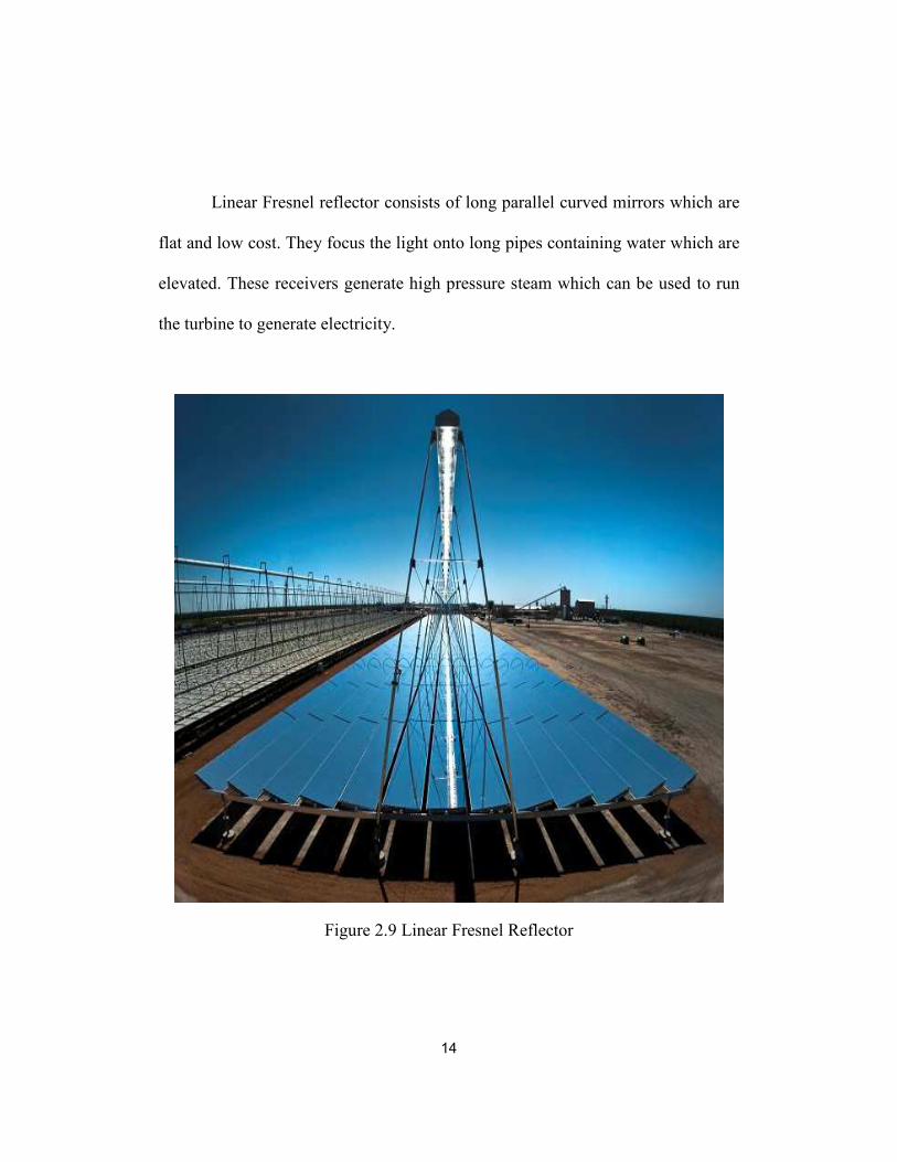
Linear Fresnel reflector consists of long parallel curved mirrors which are
flat and low cost. They focus the light onto long pipes containing water which are
elevated. These receivers generate high pressure steam which can be used to run
the turbine to generate electricity.
Figure 2.9 Linear Fresnel Reflector
15
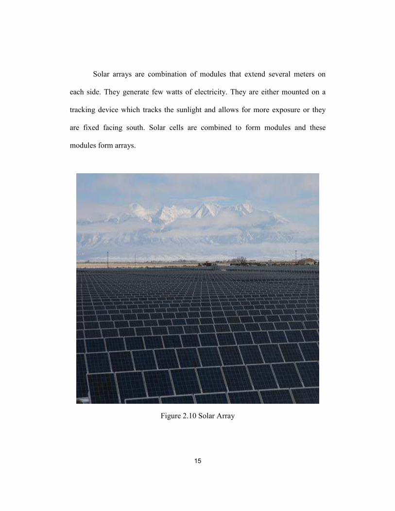
Solar arrays are combination of modules that extend several meters on
each side. They generate few watts of electricity. They are either mounted on a
tracking device which tracks the sunlight and allows for more exposure or they
are fixed facing south. Solar cells are combined to form modules and these
modules form arrays.
Figure 2.10 Solar Array

16
Chapter 3
ABSORPTION REFRIGERATION REVIEW
3.1 Absorption Refrigeration
Absorption refrigeration uses thermal energy for compression rather than
conventional electric compressors. This eliminates the use of electric
compressors. The form of energy input to the absorption refrigeration process is
heat as compared to the work provided by motor in the traditional vapor
compression process.
3.2 Solar powered absorption chiller
The basic absorption refrigeration principles are:
1. Flow of heat occurs from hot surfaces to cold surfaces.
2. Decrease in the pressure above the liquid decreases its boiling point.
3. Heating of the liquid turns it into vapor and the vapor condenses to form
liquid.
Absorption chiller uses a combination of lithium bromide and water in the
process. Water acts as a refrigerant and lithium bromide acts as an absorbent. The
affinity of water and lithium bromide makes it a suitable pair for this process and
is preferred over water and ammonia configuration because of the disadvantages
such as high pressure, volatility, toxic nature and corrosive action. The lithium
bromide and water combination is nonvolatile and eliminates the need of rectifier
in the system.

17
There are four main components of an absorption chiller:
1. Generator
2. Condenser
3. Evaporator
4. Absorber
Generator:
The input to the generator is the hot water which is stored in the storage
tank obtained by solar water heating. The generator consists of a mixture of
lithium bromide - water which is heated by the hot water. The inlet temperature to
the generator ranges between 70⁰C -88⁰C. When the water in the storage tank
reaches within the range of the inlet temperature it passes to the generator in
which it converts the water in the mixture of lithium bromide - water to vapor
leaving behind the LiBr solution which is called the strong solution.
Condenser:
The condenser houses a set of tubes carrying cold water being circulated
from a cooling tower. The water vapor from the generator condenses on the tubes
and trickles down the condenser. The water droplets then flow to the evaporator.
Evaporator:
In the evaporator the liquid vaporizes due to low pressure which in turn
helps to cool the required space. The absorption chiller unit is divided into 4
chambers, the upper half consists of generator and condenser and the lower half

18
consists of evaporator and absorber. The pressure difference between the upper
and lower chambers is about the ratio of 1:10.
Absorber:
The strong solution from the generator flows to the absorber through a
heat exchanger. The water vapor coming into the absorber is absorbed by the LiBr
solution, this weak solution is then sent to the generator through the heat
exchanger. In the heat exchanger the strong solution containing LiBr preheats the
weak solution from the absorber which is a mixture of LiBr-water. The chilled
water temperature from the evaporator should be maintained in the range of 5-
7⁰C.
Figure 3.1 Absorption Chiller Schematic

19
Absorption chillers are classified based on the energy input as follows:
1. Gas driven absorption chillers
2. Hot water driven absorption chillers
They are also classified as:
1. Single effect absorption chillers
2. Multi effect absorption chillers
In multi effect absorption systems the heat rejected at a higher temperature is
used as an input for the lower stage for heating of the fluid. Multi effect
absorption systems have a higher range of coefficient of performance values when
compared to the single effect absorption systems.
3.3 Vacuum tube solar panels
Vacuum tube solar panels operate on the principle that black body absorb
maximum radiation when compared to other bodies and by the principle that
water boils at lower temperature with decrease in air pressure by evacuating the
tube. They are also called as evacuated tubes. It consists of four main parts they
are:
1. Evacuated tube: It absorbs solar energy and converts it into usable heat.
2. Heat pipe: It is a vacuum tube made of pure copper which transfers the
heat from the evacuated tube to the manifold.
3. Manifold: It is an insulated box which consists of the header pipe to which
number of heat pipes are connected.

20
4. Mounting frame: The mounting frame holds the manifold and rest of the
system and can be adjusted accordingly.
Figure 3.2 Evacuated tube solar panels
Evacuated tube is made of two glass tubes which are extremely strong.
The outer tube allows the light rays to pass through it with minimal reflection.
The inner tube is coated with a selective material with high radiation absorbing
properties and very minimal reflection. These borosilicate tubes are fused together
and the air in between them is evacuated to form vacuum.

21
Figure 3.3 Evacuated Tube
Heat pipe contains purified water and some additives which boil at 30 ⁰C
or 86 ⁰F due to decreased air pressure. When the tube is heated above 30 ⁰C the
liquid vaporizes and these vapors rise to the top of the tube and transfer the heat to
the header pipe within the manifold. The vapors then condense and collect at the
bottom of the tube and this process continues.

22
Figure 3.4 Heat Pipe
Heat pipe is a vacuum tube which consists of liquid which boils at a low
temperature. When the pipe is heated the liquid boils and converts to vapor and
rises to the top of the tube carrying heat. This heat is transferred to the header pipe
which is located inside the manifold. The liquid then condenses and trickles back
to the bottom of the tube. This process continues repeatedly and is a faster mode
of heat transfer. The heat transferring fins located inside the evacuated tube helps
in increasing the heat transfer to the manifold.

23
3.4 Difference between vapor compression and absorption refrigeration
Vapor compression systems are small in size containing moving parts. The
system performance is dependent on evaporator temperatures. Due to the presence
of moving parts in the system noise and vibration exits. Maintenance is required
to ensure proper functioning of the machine. Coefficient of performance
decreases with the variation in loads.
Absorption refrigeration systems are larger in size and do not contain
moving parts. Performance of the system is not entirely dependent on evaporator
temperatures. Due to the absence of moving parts in the system no noise and
vibration exist. This also reduces the maintenance required for the system.
Coefficient of performance does not decrease with the variation in the load. The
power consumption of such systems are less when compared to that of a vapor
compression system.
Figure 3.5 Vapor Absorption system

24
Figure 3.6 Vapor Compression System
3.5 Literature Review
Absorption systems have been studied in great detail. Some of the topics
discussed in the literature papers are mass and energy balance between
components of the system, construction details of each component based on the
dimensions, different working fluids and arrangements within the system, impact
of working fluid mixtures on the coefficient of performance, 1st and 2nd law
analysis of the system, losses and thermodynamic analysis on single effect and
double effect systems, use of heat pipe exchanger over the conventional heat
exchanger.

25
Chapter 4
PERFORMANCE CHARACTERISTICS
4.1 Input Parameters and procedures
The performance characteristics for a single effect lithium bromide – water
absorption chiller is calculated using the thermodynamic equations listed in [23]
The input parameters used in calculating the performance characteristics are:
1. Generator inlet temperature – 85 ⁰C
2. Evaporator outlet temperature – 8 ⁰C
3. Condenser cooling water temperature – 30 ⁰C
4. Absorber cooling water temperature – 30 ⁰C
5. Exchanger effectiveness – 0.7
6. Evaporator heat capacity – 23 kw or kcal/hr
The generator temperatures are varied in the increments of 5 ⁰C starting from 85
⁰C till 105 ⁰C. Evaporator temperatures are varied in the increments of 0.5 ⁰C
starting from 8 ⁰C till 10 ⁰C. Condenser and Absorber cooling water temperatures
are varied in the increments of 0.5 ⁰C each starting from 30 ⁰C till 32 ⁰C. The
exchanger effectiveness is kept at a constant value of 0.7 throughout the
calculation. Evaporator heat capacity is varied in the increments of 1000 kcal/hr
starting from 19789 kcal/hr to 23789 kcal/hr. The performance characteristics are
calculated based on these values and tables are created in Microsoft Excel
software.

26
4.2 Tabulated Results
Table 4.1 Coefficient of Performance for different evaporator and generator heat
capacities
Rate of Heat
Transfer (Qe)
kcal/hr
Rate of Heat Transfer (Qg)
kcal/hr
Coefficient of
Performance (COP)
19789.67 24183.0593 0.82
20789.67 25577.2522 0.81
21789.67 26997.2067 0.81
22789.67 28440.1893 0.80
23789.67 29904.3748 0.80
Table 4.2 Evaporator Pressure for different evaporator temperatures
Evaporator Temperature (te) ⁰C Evaporator Pressure (Pe) mmHg
8 7.99
8.5 8.26
9 8.55
9.5 8.85
10 9.15
Table 4.3 Condenser Pressure for different condenser temperatures
Condenser Temperature (tc) ⁰C Condenser Pressure (Pc) mmHg
30 31.81
30.5 32.74
31 33.69
31.5 34.66
32 35.66

27
4.3 Graphical Results
Figure 4.1 Effect of Condenser Temperature values on COP
The above figure shows the effect of condenser temperature values on the COP of
the system. It can be seen that increasing the cooling water temperature to the
condenser results in decrease of the Coefficient of Performance. Therefore
condenser temperatures need to be kept as low as possible in order to maintain a
high COP. Keeping the temperature of the cooling water low helps it to absorb
maximum heat rejected from the mixture of lithium bromide and water.
0.78
0.79
0.79
0.80
0.80
0.81
0.81
0.82
0.82
0.83
30 30.5 31 31.5 32
Coef
fici
ent
of
Per
form
an
ce
Condenser Temperature (tc) ⁰⁰⁰⁰C
COP vs Condenser Temperature
28
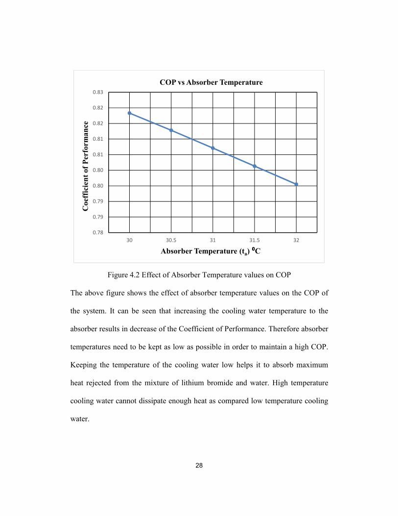
Figure 4.2 Effect of Absorber Temperature values on COP
The above figure shows the effect of absorber temperature values on the COP of
the system. It can be seen that increasing the cooling water temperature to the
absorber results in decrease of the Coefficient of Performance. Therefore absorber
temperatures need to be kept as low as possible in order to maintain a high COP.
Keeping the temperature of the cooling water low helps it to absorb maximum
heat rejected from the mixture of lithium bromide and water. High temperature
cooling water cannot dissipate enough heat as compared low temperature cooling
water.
0.78
0.79
0.79
0.80
0.80
0.81
0.81
0.82
0.82
0.83
30 30.5 31 31.5 32
Coef
fici
ent
of
Per
form
an
ce
Absorber Temperature (ta) ⁰⁰⁰⁰C
COP vs Absorber Temperature

29
Figure 4.3 Effect of Evaporator Temperature values on COP
The above figure shows the effect of evaporator temperature values on the
coefficient of performance of the system. It can be seen that the coefficient of
performance gradually increases with the increase in evaporator temperature
values. Therefor it is ideal to maintain the evaporator temperatures within the
range of 8-10 ⁰C.
0.8
0.805
0.81
0.815
0.82
8 8.5 9 9.5 10
Coef
fici
ent
of
Per
form
an
ce
Evaporator Temperature (te) ⁰⁰⁰⁰C
COP vs Evaporator Temperature

30
Figure 4.4 Effect of Generator Temperature values on COP
The above figure shows the effect of generator temperatures on the coefficient of
performance of the system. It can be seen that as the generator temperature
increases the coefficient of performance of the system increases. This also helps
in deciding the type of collectors that can be used to obtain these temperatures.
There also exists a low generator temperature limit below which the cycle does
not operate. The ideal temperature range for generator temperature is between 85
– 100 ⁰C.
0.79
0.795
0.8
0.805
0.81
0.815
0.82
85 90 95 100 105
Coef
fici
ent
of
Per
form
an
ce
Generator Temperature (tg) ⁰⁰⁰⁰C
COP vs Generator Temperature
31
Chapter 5
GASKETED PLATE HEAT EXCHANGER
A plate heat exchanger uses plates to transfer heat between fluids. The
entire surface area of the plates are exposed to the fluids thereby allowing better
heat transfer and to decrease the temperature rapidly. Large sized plate heat
exchangers use gasket between the plates and small sized heat exchangers are
generally brazed. It was invented in 1923 by Dr. Richard Seligman. The plates
used in this heat exchanger is usually made of stainless steel and are obtained by
pressing of metal plates. The plates are arranged in such a way that there are
troughs in direction of the flow of liquid between the plates. These plates are then
compressed to form one unit.
The fluid flows through the channels located in the plates when they are
compressed to form one unit, the channels form a parallel flow arrangement
alternating between the hot and cold fluids respectively. High heat transfer
coefficient can be achieved in such heat exchangers due to more exposure of the
surface area of the plates to the fluids.
Based on the flow of fluid in the headers there are two possible
configurations they are:
1. U – Type
2. Z – Type

32
Figure 5.1 Types of configuration in PHE
Some of the advantages of using plate heat exchanger over shell and tube
heat exchanger are:
1. Compact and smaller in size
2. Replacement of plates is easy
3. High heat transfer coefficient
4. Maintenance is easy
There are two types of corrugation within the plates of the heat exchanger
they are:
1. Intermating
2. Chevron
33
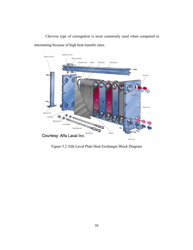
Chevron type of corrugation is most commonly used when compared to
intermating because of high heat transfer rates.
Figure 5.2 Alfa Laval Plate Heat Exchanger Block Diagram

34
Chapter 6
STEPWISE PERFORMANCE & THERMAL ANALYSIS OF ABSORPTION
CHILLER COMPONENTS
The stepwise performance & thermal analysis is carried out by using the
following thermodynamic equations listed in [21]
6.1 Evaporator Performance and Thermal Analysis
The brazed plate heat exchanger considered for the analysis of evaporator
is “Alfa Laval AC30EQ/ACH30EQ”.
Figure 6.1 Alfa Laval Brazed Heat Exchanger AC30EQ/ACH30EQ

35
Figure 6.2 Alfa Laval Brazed Plate Heat Exchanger AC 30/ACH 30 Product
Specifications
The condensed refrigerant liquid from the condenser flows into the
evaporator due the pressure difference between the condenser and evaporator. The
refrigerant liquid boils on the chilled water tubes thereby converting to vapor and

36
passes to absorber. The refrigerant vapor absorbs the heat from the cooling water
being circulated from the space to be cooled.
Table 6.1 Process and constructional specifications for evaporator
Symbol Name Value Units
a Height 0.325 m
b, Lw width 0.095 m
Lv Vertical Connection distance 0.269 m
Lh
Horizontal Connection
distance 0.039 m
Lc Plate Pack Length 0.053 m
DP Port Diameter 0.03 m
ṁ
Flow Rate 0.8 kg/sec
Flow Rate 0.17 kg/sec
T
Chilled water inlet temperature 13 ⁰C
chilled water outlet
temperature 7 ⁰C
Condensate to expansion
device 38 ⁰C
Vapor to absorber 6 ⁰C
CP Specific heat of water 4186 J/kg. k
Nt Number of plates 20
t plate thickness 0.0006 m
Ae Heat exchanger area 1 m^2
μh Viscosity of hot fluid 0.001 N.s/m^2
μc Viscosity of cold fluid 0.001 N.s/m^2
Total Fouling Resistance 0.0001 m^2.K /W
k Thermal Conductivity of SS 17 W/m.K
37
Results obtained:
Table 6.2 Safety Factor for Evaporator
Fouled Surface
heat load “Qf” kW Required heat load “Qr” kW Safety Factor "CS"
29611.4 23232.3 1.27
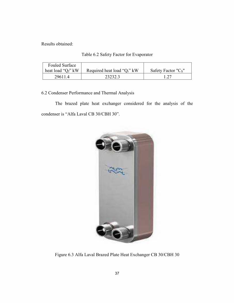
6.2 Condenser Performance and Thermal Analysis
The brazed plate heat exchanger considered for the analysis of the
condenser is “Alfa Laval CB 30/CBH 30”.
Figure 6.3 Alfa Laval Brazed Plate Heat Exchanger CB 30/CBH 30

38
Figure 6.4 Alfa Laval Brazed Plate Heat Exchanger CB 30/CBH 30 Product
Specifications
The refrigerant vapor from the generator enters into the condenser and
condenses over the tubes of cooling water thereby forming droplets. The heat
from the vapor is absorbed by the cooling water which exits the condenser and is
sent to a cooling tower.

39
Table 6.3 Process and constructional specifications for Condenser
Symbol Name Value Units
a Height 0.313 m
b, Lw width 0.113 m
Lv Vertical Connection distance 0.25 m
Lh Horizontal Connection distance 0.05 m
Lc Plate Pack Length 0.056 m
DP Port Diameter 0.03 m
ṁh Flow Rate of hot fluid 1.9 kg/sec
ṁc Flow Rate of cold fluid 1.8 kg/sec
T
Vapor from generator to
condenser 40 ⁰C
Condensate to expansion device 37 ⁰C
Outlet Cooling water from
condenser 36 ⁰C
Inlet cooling water to condenser 33 ⁰C
CP Specific heat of water 4186 J/kg. k
Nt Number of plates 20
t plate thickness 0.0006 m
Ae Heat exchanger area 1 m^2
μh Viscosity of hot fluid 0.001114 N.s/m^2
μc Viscosity of cold fluid 0.001428 N.s/m^2
Total Fouling Resistance 0.00005 m^2. K /W
k
Thermal Conductivity of AISI
316 16.3 W/m. K
Results obtained:
Table 6.4 Safety Factor for condenser
Fouled Surface heat
load “Qf” kW Required heat load “Qr” kW Safety Factor "CS"
29611.4 23232.3 1.27

40
6.3 Generator Performance and Thermal Analysis
The brazed plate heat exchanger considered for the analysis of the
condenser is “Alfa Laval CB 76/CBH 76”.
Figure 6.5 Alfa Laval Brazed Plate Heat Exchanger CB 76/CBH 76

41
Figure 6.6 Alfa Laval Brazed Plate Heat Exchanger CB 76/CBH 76 Product
Specifications
Generator consists of a mixture of lithium bromide and water. The water
in the mixture acts as the refrigerant and the lithium bromide acts as an absorbent.
The water is converted into vapor by means of solar energy input from the

42
collectors. The refrigerant vapor passes over to the condenser where it condenses
over the cooling water tubes. The absorbent remaining in the generator is known
as strong solution due to the absence of the refrigerant and it flows to the solution
heat exchanger where it transfers the heat onto the incoming weak solution from
the absorber. In other words preheating the weak solution before it enters the
generator.
Table 6.5 Process and constructional specifications for Generator
Symbol Name Value Units
a Height 0.618 m
b, Lw width 0.191 m
Lv Vertical Connection distance 0.519 m
Lh Horizontal Connection distance 0.092 m
Lc Plate Pack Length 1.057 m
DP Port Diameter 0.03 m
ṁh Flow Rate of hot fluid 1.1 kg/sec
ṁc Flow Rate of cold fluid 0.8 kg/sec
T
Hot water inlet to generator 85 ⁰C
outlet hot water from generator 80 ⁰C
strong solution outlet from
generator 74 ⁰C
weak solution inlet to generator 67 ⁰C
CP Specific heat of water 4186 J/kg. k
Nt Number of plates 20
t plate thickness 0.0006 m
Ae Heat exchanger area 6 m^2
μh Viscosity of hot fluid 0.001114 N.s/m^2
μc Viscosity of cold fluid 0.001428 N.s/m^2
Total Fouling Resistance 0.00005 m^2. K /W
k
Thermal Conductivity of AISI
316 17 W/m. K

43
Results obtained:
Table 6.6 Safety Factor for Generator
Fouled Surface heat
load “Qf” kW
Required heat load “Qr”
kW Safety Factor "Cs"
24223.7 23232.3 1.04
6.4 Absorber Performance and Thermal Analysis
The brazed plate heat exchanger considered for the analysis of the
condenser is “Alfa Laval CB 30/CBH 30”.
Figure 6.7 Alfa Laval Brazed Plate Heat Exchanger CB 30/CBH 30

44
Table 6.7 Process and constructional specifications for Absorber
Symbol Name Value Units
a Height 0.313 m
b, Lw width 0.113 m
Lv Vertical Connection distance 0.25 m
Lh Horizontal Connection distance 0.05 m
Lc Plate Pack Length 0.056 m
DP Port Diameter 0.03 m
ṁh Flow Rate of hot fluid 1.4 kg/sec
ṁc Flow Rate of cold fluid 1.8 kg/sec
T
outlet cooling water from
absorber 34 ⁰C
Inlet cooling water to Absorber 30 ⁰C
Intermediate Solution 36 ⁰C
weak solution outlet 33 ⁰C
CP Specific heat of water 4186 J/kg. k
Nt Number of plates 20
t plate thickness 0.0006 m
Ae Heat exchanger area 1.2 m^2
μh Viscosity of hot fluid 0.001114 N.s/m^2
μc Viscosity of cold fluid 0.001428 N.s/m^2
Total Fouling Resistance 0.00005 m^2. K /W
k
Thermal Conductivity of AISI
316 17 W/m. K
Results obtained:
Table 6.8 Safety Factor for Absorber
Fouled Surface heat load
“Qf” kW
Required heat load “Qr”
kW
Safety Factor
"Cs"
26585.9 23023 1.15

45
The refrigerant vapor from the evaporator passes to the absorber where it
is absorbed by the strong solution from the generator containing lithium bromide.
The affinity of water and lithium bromide helps in absorbing of water. This
solution is now called the weak solution due to the presence of water. This
solution then passes into the solution heat exchanger wherein it is preheated by
the incoming strong solution from the generator. In this way the process continues
repeatedly.

46
Chapter 7
PERFORMANCE CHARACTERISTICS CALCULATIONS WEBPAGE
This webpage is used in calculating the performance characteristics of a
single effect lithium bromide/water absorption chiller unit for IT-POD having
evaporator capacity of 23kW. The input values are:
1. Generator Temperature (tg) ⁰C
2. Evaporator Temperature (te) ⁰C
3. Condenser Temperature (tc) ⁰C
4. Absorber Temperature (ta) ⁰C
5. Exchanger Effectiveness (EL)
6. Evaporator heat capacity (Qe) kW
Figure 7.1 Performance Characteristics Webpage calculations

47
Figure 7.2 Performance Characteristics calculated values

48
Chapter 8
CONCLUSION
Some of the noted findings of this work are:
• Decrease in COP with increase in absorber and condenser
temperatures.
• Increase in COP with increase in evaporator and generator
temperatures.
• Ideal cooling water temperature range for condenser and absorber
temperatures are between 25 – 32 ⁰C
• Ideal chilled water temperature range for evaporator temperature is
between 7 – 10 ⁰C
• Ideal hot water temperature range for generator temperature is
between 85 – 95 ⁰C
Solar thermal cooling has tremendous potential on becoming one of the
important cooling technologies available for data centers. It paves the way for a
greener environment and future making use of the renewable energy sources.
However there are challenges that need to be addressed before implementing this
technology on a larger scale. The trends indicate the decrease in the cost of
installation of solar energy equipment thus making this technology more
preferable and widely used in the future. This analysis helps in a better
understanding of the absorption refrigeration system. It helps in deciding the

49
feasibility of such systems for small data centers. In addition to this it also helps
in sizing of the individual heat exchangers in the system. Therefore these systems
have great potential in becoming the main source of cooling in a data center
facility and making it environmental friendly.
Future work can include a detailed cost analysis of such systems for small
data centers. Study of single effect absorption chillers by considering different
types of solar collectors such as flat plate and evacuated tube collectors. Finally to
study double effect absorption chillers.

50
Appendix A
THERMODYNAMIC EQUATIONS FOR PERFORMANCE
CHARACTERISTICS OF SINGLE EFFECT LITHIUM BROMIDE/WATER
ABSORPTION CHILLER
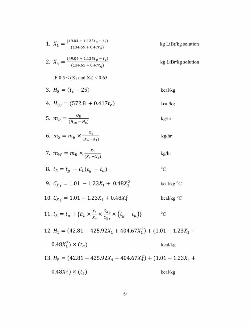
51
1. �� = (�.� � �.� ��� � ��)
(���.�� � .����) kg LiBr/kg solution
2. �� =(�.� � �.� ��� � ��)
(���.�� � .����) kg LiBr/kg solution
IF 0.5 < (X1 and X4) < 0.65
3. �� = (�� − 25) kcal/kg
4. �� = (572.8 + 0.417�&) kcal/kg
5. '( = )*
(+,- � +.) kg/hr
6. '0 = '( × 23
(23 �2,) kg/hr
7. '4 = '( × 2,
(23 �2,) kg/hr
8. �� = �5 − 67(�5 − �8) ⁰C
9. :2� = 1.01 − 1.23�� + 0.48�� kcal/kg ⁰C
10. :2� = 1.01 − 1.23�� + 0.48�� kcal/kg ⁰C
11. �� = �8 + {67 × 2,
23×
<=3
<=,× >�5 − �8?} ⁰C
12. �� = (42.81 − 425.92�� + 404.67�� ) + (1.01 − 1.23�� +
0.48�� ) × (�8) kcal/kg
13. �� = (42.81 − 425.92�� + 404.67�� ) + (1.01 − 1.23�� +
0.48�� ) × (��) kcal/kg

52
14. �� = (572.8 + 0.46�5 − 0.043��) kcal/kg
15. A� = '((�� − ��) kcal/hr
16. AB = ('C�� + '(�� − '0��) kcal/hr
17. AD = ('C�� + '(�� − '0��) kcal/hr
18. :EF = )*
)G
19. (:EF)H8I = (��� ��.��)(�����)
(��� ��.��)(�����)
20. JKLM�NOK PKQRSQ'MTUK QM�NS = <VW
(<VW)X�Y
21. F& = MT�NLSZ{7.8553 − ����(��� ��.��)
− ��. ���×�3
(��� ��.��)[} mmHg
22. F� = MT�NLSZ{7.8553 − ����(��� ��.��)
− ��. ���×�3
(��� ��.��)[} mmHg

53
Appendix B
EQUATIONS FOR PERFORMANCE ANALYSIS AND THERMAL
ANALYSIS OF PLATE HEAT EXCHANGERS
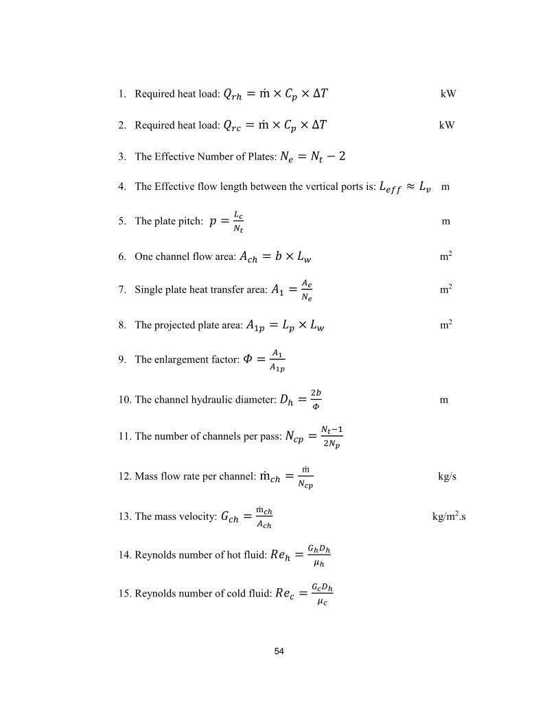
54
1. Required heat load: A\] = ṁ × :_ × ∆a kW
2. Required heat load: A\� = ṁ × :_ × ∆a kW
3. The Effective Number of Plates: b& = b� − 2
4. The Effective flow length between the vertical ports is: c&dd ≈ cf m
5. The plate pitch: P = 7�
gh m
6. One channel flow area: i�] = j × cC m2
7. Single plate heat transfer area: i� = D�
g� m2
8. The projected plate area: i�_ = c_ × cC m2
9. The enlargement factor: k = D,
D,l
10. The channel hydraulic diameter: m] = n
o m
11. The number of channels per pass: b�_ = gh��
gl
12. Mass flow rate per channel: ṁ�] = ṁ
g�l kg/s
13. The mass velocity: p�] = ṁ�q
D�q kg/m2.s
14. Reynolds number of hot fluid: JK] = Bqrq
sq
15. Reynolds number of cold fluid: JK� = B�rq
s�

55
16. Hot fluid heat transfer coefficient: ℎ] = guqv
rq W/m2.K
17. Cold fluid heat transfer coefficient: ℎ� = gu�v
rq W/m2.K
18. Clean overall heat transfer coefficient: �
w�= �
]�+ �
]q+ .�
��.� W/m2.K
19. Fouled overall heat transfer coefficient: �
wx= �
w�+ 0.00005 W/m2.K
20. Cleanliness factor: :y =wx
w�
21. Actual heat duties for clean and fouled surfaces: A� = z�i&∆aH kW
Ad = zdi&∆aH kW
22. Safety Factor: :{ =)x
)|

56
References
1. Alfa laval CB 110. Retrieved from http://www.liebelt-
webshop.com/Heizung/Waermetauscher/Alfa-Laval-CB-76/
2. Alfa laval CB 30. Retrieved from http://www.liebelt-
webshop.com/Heizung/Waermetauscher/Alfa-Laval-CB-30/
3. Alfa laval CB 30/CBH 30. Retrieved from http://cinto-
moscow.ru/_mod_files/ce_images/photoalbum/cb30.jpg
4. Alfa laval CB 76/CBH 76. Retrieved from
http://www.transmedium.pl/obrazek.php?id=1355
5. Alfa-laval ac30eq. Retrieved from
http://www.refrigeracionzelsio.es/intercambiadores-de-calor-de-
placas/1332-alfa-laval-ac30eq.html
6. Arun Babu Mysore, A., & Anoop, M. (2015). Thermal analysis of a single
stage LiBr-water abosrption system. Retrieved from
http://omega.uta.edu/~axa1640/PerformanceCharacteristics.html
7. Concentrating solar power. (2014). Retrieved from
http://www.seia.org/policy/solar-technology/concentrating-solar-power
8. DeWitt, K. (2012, December 11). Tech companies get creative in keeping
data centers cool. Retrieved from http://blog.opower.com/2012/12/tech-
companies-get-creative-in-keeping-data-centers-cool/

57
9. Efficiency - google green. Retrieved from
http://www.google.com/green/efficiency/
10. Evacuated tube solar collectors. (2015). Retrieved from
http://www.apricus.com/html/solar_collector.htm#.VayECPlVikp
11. Evacuated tube solar water heating collectors. (2014). Retrieved from
http://www.solarpanelsplus.com/evacuated-tube-collectors/
12. FHC030 heat exchanger. (2015). Retrieved from
http://spanish.alibaba.com/p-detail/FHC030-Intercambiador-de-Calor-
300000437516.html
13. Karthi. (2011, August 10). Datacenter and its classifications. Retrieved
from https://blogs.site24x7.com/2011/08/10/datacenter-and-its-
classifications/
14. Mande. (2014, February 25). Introduction on solar energy and solar power
plants. Retrieved from
https://ngsuyasa.wordpress.com/2014/02/25/introduction-on-solar-energy-
and-solar-power-plants/
15. Narayanan, V.Absorption refrigeration - overview. Retrieved from
https://web.engr.oregonstate.edu/~narayavi/absorption%20refrigeration.ht
ml
16. Plate heat exchanger. (2015). Retrieved from
https://en.wikipedia.org/wiki/Plate_heat_exchanger

58
17. Plate heat exchangers. (2015). Retrieved from
http://www.separationequipment.com/products-plate-heat-
exchangers.html
18. Rath, J., & Kleyman, B. (2013). Data center knowledge guide to modular
data centers.1 Retrieved from
http://www.datacenterexperts.com/files/modular/2_26174_IO-
Modular_DC_Guide_Mar2013-v1.pdf
19. Solar photovoltaic technologies. Retrieved from
http://solareis.anl.gov/guide/solar/pv/index.cfm
20. Water fired single-effect chillers and chiller-heaters. (2015). Retrieved
from http://www.yazakienergy.com/waterfired.htm
21. Kakaç, S., & Liu, H. (1998). Heat exchangers: Selection, rating, and
thermal design. Boca Raton, Fla: CRC Press. Retrieved from
http://uta.summon.serialssolutions.com/2.0.0/link/0/eLvHCXMwdV3fS8
MwED5kgigi1h-
1TmH_QEuW2iz3PB2FDUHdw95K46WPQ10L_vnm0hXLnI8XSHKEy
33hku8LQCoTEe_kBFNKWaWiJEljpHch0YqsUmQsZRoN84af39TrApe
5nP9yxD4ahw-sKdiKo_53K6MVBxbzyJXiZ33iZeWlHh-
Qv2XSndBOZ7NCYFOXPRyZncOAuQUBHNj1BZz0tAAv4Sx3WXFkv
7dM3M0VRLOn5TSP3RjFtshStC7Iazgt-
WX6uvYMNgphUH81NuTMHrq5Qjha4eJR5_NpawadmWw8yyr5rEMH

59
JD4IY5VMbmBk0JKZVG6vEMO_xnHmAEVbIpQ21SKC4K8nEQz7jd2
iFXyeQ3m7r8sQjlvCHdcX7uCwcvFv7_1S_QCL63uV
22. Joudi, K. A., & Lafta, A. H. (2001). Simulation of a simple absorption
refrigeration system. Energy Conversion and Management, 42(13), 1575-
1605.
23. Lansing, F. (1976). Computer modeling of a single-stage lithium
bromide/water absorption refrigeration unit.

60
Biographical Information
Abhishek Arun Babu Mysore was a graduate student in the Department of
Mechanical & Aerospace Engineering at The University of Texas at Arlington
who completed his Master’s program in summer, 2015. He received his Bachelor
of Engineering degree in Mechanical Engineering from Visvesvaraya
Technological University, India in 2013. During his Master of Science degree in
Mechanical Engineering at The University of Texas at Arlington he worked under
the Electronics MEMS & Nanoelectronics Systems Packaging Center (EMNSPC)
concentrating on the solar thermal cooling of data centers.