performance characteristics of scroll expander for co2
TRANSCRIPT

Purdue UniversityPurdue e-Pubs
International Compressor Engineering Conference School of Mechanical Engineering
2008
Performance Characteristics of Scroll Expander forCO2 Refrigeration CyclesHirokatsu KohsokabeHitachi
Masaki KoyamaHitachi
Kenji TojoHitachi Appliances
Mutsunori MatsunagaHitachi Appliances
Susumu NakayamaHitachi Appliances
Follow this and additional works at: https://docs.lib.purdue.edu/icec
This document has been made available through Purdue e-Pubs, a service of the Purdue University Libraries. Please contact [email protected] foradditional information.Complete proceedings may be acquired in print and on CD-ROM directly from the Ray W. Herrick Laboratories at https://engineering.purdue.edu/Herrick/Events/orderlit.html
Kohsokabe, Hirokatsu; Koyama, Masaki; Tojo, Kenji; Matsunaga, Mutsunori; and Nakayama, Susumu, "Performance Characteristicsof Scroll Expander for CO2 Refrigeration Cycles" (2008). International Compressor Engineering Conference. Paper 1847.https://docs.lib.purdue.edu/icec/1847

1239, Page 1
PERFORMANCE CHARACTERISTICS OF SCROLL EXPANDER FOR C02 REFRIGERATION CYCLES
Hirokatsu KOHSOKABE 1*, Masaki KOYAMA 1,
Kenji TOJ02, Mutsunori MATSUNAGA2
, Susumu NAKA YAMA2
1Hitachi, Ltd., Mechanical Engineering Research Laboratory, 832-2, Horiguchi , Hitacbinaka-shi, Ibaraki 3 12-0034, Japan FAX: 81 (29)353-3869; E-Mail: hi [email protected]
2Hitachi Appliances, Inc. , 390 Muramatsu, Shimizu-ku, Shizuoka-shi , Shizuoka 424-0926, Japan
ABSTRACT
To help lesser the effects of global warming, C0 2 refrigeration cycles are required in refrigeration and airconditioning applications. Work-output expansion devices (expanders) are needed to improve the system performances, but their efficiencies are still too low to make the systems practical. The improvement in the COP of a C0 2 refrigeration cycle is highly dependent on expander efficiency. To solve this problem, we developed a prototype of a scroll expander for C02 refrigeration cycles and studied its performance characteristics. The experimental parameters are rotational speed, inlet pressure and temperature, exit pressure, and C02 mass fl ow rate of the scroll expander. The test results show that our scroll expander had maximum measured isentropic efficiencies greater than 70%. We confirmed that our scroll expander has a high potential for making C02 refrigeration systems practical.
1. INTRODUCTION
Carbon dioxide (C02) has been receiving attention due to global environmental problems. The coefficient of perfonnance (COP) of C0 2 refrigeration cycles, however, is typically low compared to conventional hydrofluorocarbon (HFC) refrigeration cycles. The main reason for this low COP is the large throttling loss that results from a transcritical refrigeration cycle. Many researchers have been trying to improve the COP of transcritical C0 2 refrigeration cycles. The throttling loss can be reduced by replacing the expansion valve with a work-output expansion device (expander or ejector). Various types of expanders to recover the throttling loss of the C0 2 refrigeration cycles have been studied. A scroll-type fluid machine is an expander that has been utilized in an organic Rankine cycle. However, the amount of research on its performance for the C02 refrigeration cycle is relatively small. Huff et al. (2003) studied the efficiency of the scroll expander experimentally. Westphalen and Dieckmann (2006) developed a scroll expander design for C02 refrigerant-cooling systems. Fukuta et al. (2006) examined the feasibility of a scroll expander for C0 2 refrigeration cycles both theoretically and experimentally. Kim et al. (2006) analyzed a combined scroll expander-compressor unit for C02 transcritical cycles. Kohsokabe et al. (2006) showed the experimental perfonnance of a C0 2 refrigeration cycle with a combined scroll type expander and rotary type compressor unit. This paper shows the experimental performance of a prototype scroll expander and presents its basic performance characteristics.
2. FEATURE OF EXPANDER EFFICIENCY
Thi s section explains the features of the expander in comparison with the compressor. Table I shows the definitional expression of expander and compressor efficiency. Since the movement of the expander is opposite to the movement of the compressor, expander efficiency is defined as the reversal expression of compressor efficiency. Due to this
International Compressor Engineering Conference at Purdue, July 14-17, 2008
1239, Page 2
reversal fonn relation, each characteristic of the isentropic efficiency toward mechanical loss is different. Figure I shows the relationship between the mechanical loss ratio and the isentropic efficiency of the expander and compressor. This figure indicates that the isentropic efficiency of the expander is lower than that of the compressor at the same mechanical loss ratio. Therefore, the expander needs to be a low mechanical loss flui d machine. The decrease in mechanical loss is especially impmt ant in the expander with improvement in the volumetric and indicated efficiencies.
3. PROTOTYPE SCROLL EXPANDER
One of the features of the scroll type fluid machine is its low mechanical loss. Therefore, we selected the scroll type fluid machine as the expander. Figure 2 shows a prototype of a scroll expander, and the major specifications are listed in Table 2 . This scroll expander is designed for C0 2 air-conditioning systems and has about a 700 W e lectrical output at the cooling rated condition. The expander inlet volume is 2.8 cm3 and the built-in volume ratio is 2.0. The scroll mechanism consists of a fi xed scroll, an orbiting scroll , an Oldham coupling, a crankshaft, and a frame, and it is mounted in a housing case. The generator is connected to the scroll assembly. This scroll expander has a selfadjusting orbiting scroll support mechanism like our product's scroll compressors (Tsubono I. et al., 1998). Behind the orbiting scroll, a back-pressure chamber is provided . The pressure in this chamber is maintained at an intermediate range between the inlet pressure and the exit pressure. The level of back-pressure suffic ient to keep the orbiting scroll engaged with the fixed scroll can be found by the experimental data. This back-pressure mechanism reduces friction at the sliding portion between the orbiting and fixed scrolls and provides axial compliance for maintaining the seal at the scroll wrap tip clearance. The scroll expander lubricated by polyalkylene glycol (PAG) oil , which is stored in the bottom of the housing case. The oil is supplied to the bearings and other sliding surfaces by the pressure di fference between the discharge pressure in the housing case and the intermediate pressure in the back-pressure chamber.
4. EXPERIMENT
Figure 3 shows the experimental setup. Changing the electric current or voltage of the DC electronic resistive load controls the rotational speed of the expander. The temperature and pressure of the expander (inlet and exit) , the refrigerant mass flow rate, the generator power output, and the rotational speed of the expander were measured. The expander volumetric efficiency 1J v is defined by
7J v=G~ ,/G ( I) where G111 is the refrigerant theoretical mass flow rate, and G is the actual mass fl ow rate of the expander.
The expander isentropic efficiency 1J ex is given as 1J ex=Lg/(G • LJ hex • 1J g) (2)
where Lg is the generator power output, LJhex is the isentropic enthalpy difference of the expander, and 1J g is the generator efficiency.
5. TEST RESULTS
5.1 Effects of Back Pressure The control of the back-pressure was executed by adjusting the amount of gas and oil extracted from the backpressure chamber to a low pressure line at the evaporator exit with a needle valve. In the experiment, the inlet pressure and temperature, the exit pressure, and the rotational speed of the expander were kept constant. Figure 4 illustrates the relationship between the expander efficiency and the back-pressure difference. The vertical ax is represents the relative efficiency based on the maximum isentropic efficiency (1.0). The horizontal axis represents the relative pressure difference between the back-pressure and the exit pressure based on the optimum back-pressure difference (1.0). From this figure, the back-pressure difference is extremely important to improve the expander efficiency. The experiment thereafter was a result of keeping this optimum back-pressure difference.
5.2 Effects of Rotational Speed Figure 5 shows the effects of the rotational speed of the expander. In the experiment, the inlet pressure was approximately 8.2 MPa, and the inlet temperature was 36 "C . The scroll expander perfonnance was measured for the
International Compressor Engineering Conference at Purdue, July 14-1 7, 2008

1239, Page 3
exit pressure is at 4. 77, 4.21, and 3.96 MPa by changing the rotational speed from 2000 to 3500 min' 1• The optimum
rotational speed of the scroll expander was in the range of 2200 to 3400 min·1. This optimum value does not depend
on the exit pressure. The most efficient operating point is 83%. The rotational speed, inlet pressure, and exit pressure at this point was 2655 min'1, 8.3 MPa, and 4.21 MPa, respectively. The operating pressure ratio and the refrigerant mass flow rate are different in Figure 5. Next, these effects are examined.
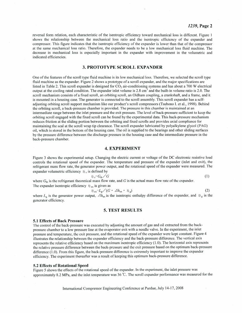
5.3 Effects of Pressure Ratio and Refrigerant Mass Flow Rate Figure 6 shows the effects of the operating pressure ratio of the expander. This figure is a re-arrangement of Figure 5 at the rotational speed of about 2800 min·1
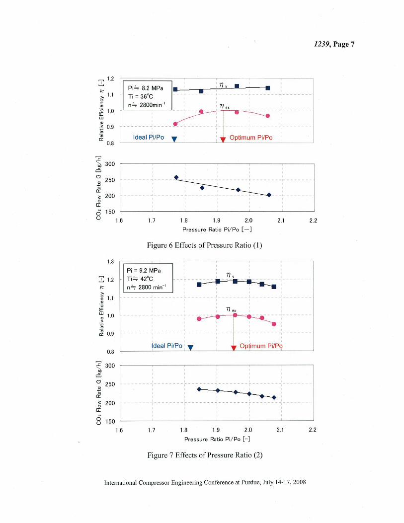
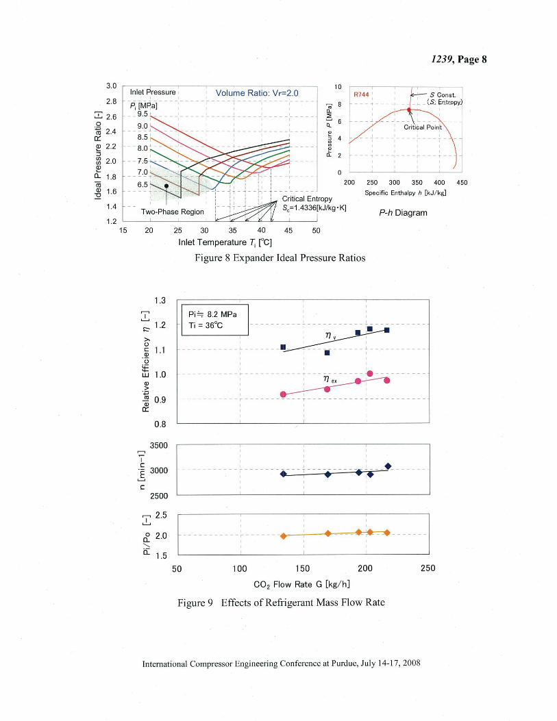
• From this figure, the optimum operating pressure ratio was about 1.92 . This value is a little larger than the ideal pressure ratio of 1.77 (refer to Figure 8) of the prototype scroll expander. Figure 7 shows the effects of the operating pressure ratio at an inlet pressure of9.2 MPa and inlet temperature
between 41-43 "C. The optimum operating pressure ratio was about 1.95. This value is a little larger than the ideal pressure ratio of 1.82. Figure 9 shows the effects of the refrigerant mass flow rate. The pressure ratio and the rotational speed are almost constant. This figure shows that the volumetric and isentropic efficiency decrease when the refrigerant mass flow rate decreases.
6. CONCLUSIONS
We have developed a prototype of a scroll expander and investigated its performance characteristics for a C02
refrigeration cycle. As a result, the following conclusions were obtained. • The scroll expander has a maximum measured isentropic efficiency of83%. • The optimum rotational speed of the scroll expander is in the range of 2200 to 3400 min-1
•
• The optimum operating pressure ratio is a little larger than the ideal pressure ratio of the expander. • Our scroll expander has a high potential for making C02 refrigeration systems practical.
NOMENCLATURE
G Refrigerant Mass Flow Rate (kg/h) T Temperature ("C)
Lad Adiabatic (Isentropic) Power (W) .LlLm Mechanical Loss (W)
Lg Generator Output Power (W) 77 ex Expander isentropic Efficiency (-)
Li Indicated Power (W) 7Jv Volumetric Efficiency ( - )
L, Shaft Power (W) Subscripts n Rotational Speed (min-1
) inlet p Pressure (MPa) 0 exit pb Back-Pressure (MPa)
REFERENCES
Huff H.J., Radermacher R., Preissner M ., 2003, Experimental investigation of a Scroll Expander in a Carbon Dioxide Air-Conditioning System, Proc. of the 21'' fiR International Congress of Refrigeration, ICR485.
Westphalen D., Dickman J., 2006, Scroll Expander for Carbon Dioxide Cycle, Proceedings of the 11'" International Refrigeration and Air-Conditioning Conference at Purdue, R063.
Fukuta M., et a!., 2006, Performance of Scroll Expander for C02 refrigeration Cycle, Proceedings of the 18th International Compressor Engineering Conference at Purdue, C I 09.
Kim H.J ., et al. , 2006, Numerical Simulation on Scroll Expander-Compressor Unit for C02 Trans-Critical Cycles, Proceedings o.fthe 18th international Compressor Engineering Conference at Purdue, C l04.
Kohsokabe H., et al. , 2006, Basic Operating Characteristics of C02 Refrigeration Cycles with Expander-Compressor Unit, Proceedings of the 11'" International Re.fi·igeration and Air-Conditioning Conference at Purdue, R 159.
Tsubono 1., et al., 1998, New Back-Pressure Control System Improving the Annual Performance of Scroll Compressor, ASH RAE Transactions, Vol.l 04, 4133.
International Compressor Engineering Conference at Purdue, July 14-17,2008

Concept Chart
Isentropic Efficiency
Volumetric Efficiency
Indicated Efficiency
Mechanical Efficiency
1239, Page 4
Table 1 Definitions of Expander Efficiency
"0 ro
Compressor
'7~Z:' · ·~
L. : Shaft Power
T/ ad= Lad L.
Tlv"T/i"T/m
G T/ =-
v G,, G :Flow Rate
- L ,, L ; : Indicated T/ i- L
I Power
- L ; Ls= L ;+ .LlLm Tlm-L
s
1=:" 0.6
>.. (_) c Q)
Expander
out~'"'"' ~~ L ad
Lad : Adiabatic Power
L. T/ - - - Tl v"T/ i" T/ m ex - L -lid
G T/ = ____!jJ__ G,, : Theoretical
v G Flow Rate
- ~ L ,, : Theoretical T/ · -I L ,, Power
Tim=~ · Ls= L r.LlLm I
L1 L. : mechanical loss
;g 0.4 1----+--- ---j: ......... ~~'k---=-d:--___:=-1 w (_)
·c. 0 -E 0_2 TJ ;: Indicated Eff.
3l L1L m: Mech. Loss
L ;: Indicated Power
0
0 0.2 0.4 0.6 0.8
Mechanical Loss Ratio LlL m/ L ; [-]
Figure 1 Comparison of Expander and Compressor Efficiencies
International Compressor Engineering Conference at Purdue, July 14-17, 2008

Fixed Scroll Housing Case
(Pd)
1239, Page 5
Inlet Pipe 1'---l.,.........t::-,--;::r::=-::::;~~c_, ( P;)
Orbiting Scroll
Oldham Coupling
Hermetic Terminal
Sub Frame
<P 112
Figure 2 Prototype Scroll Expander
Table 2 Major Specifications
Expander Type Scroll
Wrap Curve Involute
Inlet Volume:Vi 2.8 cm3/rev.
Volume Ratio:Vr 2.0
Oil PAG (VG100)
Back-Pressure Chamber (Pb)
Main Bearing
Lubricating Oil
Oil Supply Pressure Difference
DC Electric Resistive Load
Oil control valve
Figure 3 Experimental Setup
Compressor
®: Pressure
(!) :Temperature
International Compressor Engineering Conference at Purdue, July 14-17, 2008

~ 1.3 I ~ 1.2
~ 1.1 c -~ 0 1.0 ~ w 0.9
C1)
>
Pi = 8.2 MPa, Ti = 36°C
Po = 4.1 MPa n = 2800 min- 1
!
,------ ~-------r-----i i
1239, Page 6
~ 0.8 ----- T -~------,------~-- ----r------C1)
0::: 0.7
0.0
1.2 ,.--,
~ 1.1 1:::-
>-0
1.0 c -~ 0
~ w 0.9
C1)
> -.:;; .!11 0.8
C1)
0:::
0.7
~ 2.5 0
a.. " a: 2.0 0
·.;::; <'0
0::: 1.5 C1) ....
::I 1/) 1/)
C1)
1.0 .... a..
'2 300 " bD
.:s:. &.......J
0 250 -
C1) ..... <'0
0:::
:!: 200 0
u::: N
0 150 (_)
1000
i Optimum Ll P
0.2 0.4 0.6 0.8 1.0 1.2 1.4
Relative Pre ssure Difference .L!P=Pb- Po [- ]
Figure 4 Effects ofBack-Pressure
Pi"=;: 8.2MPa Ti = 36°C
Po [MPa] -41.-i.- - 4.77 • • 4.21
-- - -- 3.96
- - - -~- - - :._ - - - - ..J -
I ~ ~- --- ~ - L --------
Optimum n
'
Po [MPa] _...., __ 4.77
. ---- _# · --~. - -,. . -... ,.,. .• .,_.-•• ---- ---·--·-*-..- ,..·--·
----- 4.21 -·• - · 3.96
Po [MPa] --i&-- 4.77 ......- 4.21
- ·• - · 3.96
1500
I
------------~--------~--------~--------1
I I A
I -I -~--...--a.--A I - - _I _ - - - k.-= -~ - - - - - - - - - - - - - - - - l - - - - - - - -
I I
I •••••• :
-----\=-~~ -----· -_ ... . -.. --~ ·-· --------I I
2000 2500 3000 3500 4000
Rotational Speed n [min- 1]
Figure 5 Effects of Expander Rotational Speed
International Compressor Engineering Conference at Purdue, July 14-1 7, 2008
,......, 1.2 ...!.... !::" >-1.1 0 c Q)
Pi='=;: 8.2 MPa
I Ti = 36°C n='=;: 2800min-1
~ 1.0 r _ ] 0.9 ----
"' Q; 0::: Ideal Pi/Po
0.8
......., .£ '-... 300 bJ) .:£ L-J
<.? 250
Q) +'
"' 0:::
3: 200 0
u::: "' 150 0
1239, Page 7
• • ... __ !!I - -1--------
_J _______ _
Optimum Pi/Po ----'-----'
(.) 1.6 1.7 1.8 1.9 2.0 2.1 2.2
Pressure Ratio Pi/ Po [-]
Figure 6 Effects of Pressure Ratio (1)
1.3
Pi= 9.2 MPa
::!::: 1.2 - Ti ='=;: 42°C !::" n='=;: 2800 min- 1
>-g 1.1
__________ .J _____ _ _ L _______ J ______ _ _
Q)
"(J
~ ~ 1.0 > ·.;::;
"' ~ 0.9
......., ~ 300 bJ) .=.
<.? 250 Q) +' ro 0:::
~ 200 u::: "' 8 150
1.6
I
: n ex - ~-- ------ ~---~---------
I --------,-------- r- - -- - ----------I
I
I ---~------
1.7 1.8 1.9 2.0
Pressure Ratio Pi/ Po [- ]
Figure 7 Effects of Pressure Ratio (2)
2.1 2.2
International Compressor Engineering Conference at Purdue, July 14-1 7, 2008
3.0
2.8
:::!: 2.6 0
~ 2.4 0:: ~ 2.2 ::::l (/') 2.0 (/') <I> L..
0... 1.8 (ij <I> 1.6 ~
1.4
1.2 15
1239, Page 8
Inlet Pressure 10 .------~~~-~-~
I R744 Volume Ratio: Vr=2.0
P; [MPa] 9.5 '-
9.0
20
,., I
L-1
~
>-(.)
c .!E (.)
~ w
Q)
> ·.;::; ~ Q)
0:::
~
I c
1.3
1.2
1 .1
1.0
0 .9
0.8
3500
l. 3000
c 2500
I 2.5 L-1
0 2.0 0... ""-a:: 1.5
- , ____________ J _________ _
j ;~ -------
25 30 35 40 45 50
"' 8 ~ c.. 6 Q.. 6 ~
0
200
Critical Point
250 300 350 400
Specific Enthalpy h [kJ/ kg]
P-h Diagram
Inlet Temperature T; [0C]
Figure 8 Expander Ideal Pressure Ratios
Pi=;: 8.2 MPa I
I .
- - - - -,----; ~~---
-----------L- -----~ i ·----------1 • I
I I I
---- - ----~-----------~--- - - - --- -- 11 - - - -- ---- -
~ -----------~-----------T - -- ------T--- --------
1
l------ -------------. -- ~ ... -. ---- ~ :. _ -•- l t------- ~---- • • +-·------ 1
50 100 150 200 250
C02 Flow Rate G [kg/ h)
Figure 9 Effects of Refrigerant Mass Flow Rate
International Compressor Engineering Conference at Purdue, July 14-1 7, 2008
--j
450