Performance-Based Seismic Design of Tanks with Energy
25
Performance-Based Seismic Design of Tanks with Energy-Dissipating Anchors Dr. Praveen K. Malhotra, P.E. 8 th International Conference on Flat Bottom Tanks November 6 – 7, 2012, Munich, Germany
Performance-Based Seismic Design of Tanks with Energy-Dissipating Anchors
Dr. Praveen K. Malhotra, P.E.
8th International Conference on Flat Bottom Tanks November 6 – 7, 2012, Munich, Germany
Presenter
Presentation Notes
This presentation will be made at the Flat Bottom Tanks’ conference in Munich, Germany in November 2012.
2 of 24
Outline
• Traditional seismic design • Performance-based seismic design • Seismic design with energy-dissipating anchors
Presenter
Presentation Notes
First, the traditional (code-based) seismic design is discussed. The ‘shortcomings’ of traditional seismic design are identified. Next, the performance-based seismic design of tanks is discussed. Finally, the use of energy-dissipating anchors to reduce seismic loads on tank and foundation is discussed.
3 of 24
Traditional (Code-Based) Seismic Design
• H = 18 ft • R = 15 ft • ts = 0.14 in • ta = 0.11 in
• Ti = 0.087 s • mi = 480 kip • hi = 7.7 ft
Housner-Veletsos Model
Presenter
Presentation Notes
In a traditional (code-based) seismic design, the tank is assumed rigidly attached to a rigid foundation. A mechanical model of the tank-liquid system is generated assuming that the wall (shell) of the tank is flexible. In this example, a 95,000 gallon steel tank of radius R = 15 ft is filled with water to a height of H = 18 ft. The thickness of shell bottom is ts = 0.14 in and the thickness of bottom plate annular is ta = 0.11 in. The impulsive period of the tank is Ti = 0.087 s. The impulsive mass is mi = 480 kip and the height of the impulsive mass is hi = 7.7 ft. The convective (sloshing) mass does not contribute significantly to the forces (moments and shears) in a tank with sufficient freeboard. For the purpose of this discussion we ignore the convective mass.
4 of 24
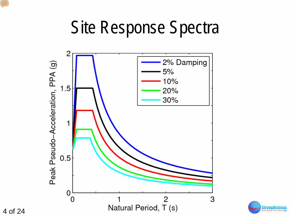
Site Response Spectra
Presenter
Presentation Notes
The response spectrum is a plot between the natural period of the system and the response acceleration (acceleration ‘seen’ by the system) for a specific value of damping. The site-specific response spectra for various values of damping are shown on this slide. The damping refers to the energy-dissipation capacity of the tank-liquid system. Note that the response acceleration reduces with increase in natural period or with increase in damping.
5 of 24
5% Damping Site Response Spectrum • Response
acceleration = 1.5 g
Presenter
Presentation Notes
In the absence of better information, the default value of damping is assumed to be 5% of critical. (A critically damped system is so heavily damped that it does not oscillate when given an initial disturbance. Shock-absorbers in cars or door closers are critically damped. Most Civil Engineering systems have a fraction of critical damping.) Assuming 5% of critical damping, the acceleration ‘seen’ by the tank of natural period Ti = 0.087 s is 1.5 g.
6 of 24
Base Shear and Overturning Moment
Base Shear = 480×1.5 = 720 kip
Overturning Moment = 720×7.7 = 5,540 kip-ft
Presenter
Presentation Notes
For a response acceleration of 1.5 g (previous slide), the base shear in the tank is 720 kip and the overturning moment is 5,540 kip-ft. These are the elastic values of base shear and overturning moment calculated from a linear elastic analysis of the tank. The design values of base shear and overturning moment (according to codes) are obtained by reducing the elastic values by load reduction factor R. The basis of load reduction factor is discussed next.
7 of 24
Load Reduction Due to Period Elongation • Period elongates
due to: – Foundation flexibility – Base uplifting – Base sliding
Presenter
Presentation Notes
It is assumed that the tank has some additional sources of flexibility which are not considered in the traditional (code-type) analysis. These are: (1) flexibility of the soil below the foundation, (2) partial uplifting of the tank base during strong shaking, and (3) sliding of the tank base during strong shaking. As a result of these flexibilities, the effective period of the tank increases as it ‘sees’ higher and higher accelerations. The net effect of these flexibilities is to reduce the acceleration ‘seen’ by the tank by a ductility factor R.
8 of 24
Load Reduction Due to Damping Increase • Damping increases
due to: – Radiation of energy
through foundation – Plastic-yielding – Base sliding
Presenter
Presentation Notes
It is further assumed that the damping of the tank during strong shaking will be more than 5% of critical. The sources of additional damping are: (1) radiation of energy through the foundation; (2) plastic yielding in the base plate due to uplifting; and (3) sliding of the tank base. The effect of additional damping is to reduce the acceleration ‘seen’ by the tank by a damping factor R.
9 of 24
Load Reduction Due to Overstrength • Reasons for
overstrength: – Redundancy in
load path (?) – Safety factors
Presenter
Presentation Notes
Finally, the actual strength of tanks is assumed to be greater than their calculated strength due to safety factors used in traditional (code-based) design. This provides an additional justification for reducing the elastic response acceleration by an overstrength factor R.
10 of 24
Judgment-Based Load Reduction Factor
• R = Rµ·Rδ·RΩ = 3.5 for self anchored tanks 4.0 for mechanically anchored tanks
Presenter
Presentation Notes
In traditional seismic design, the reduction factors R, R, and R are not explicitly computed for the specific tank. A judgment-based lump-sum reduction factor of R = 3.5 or 4 is used to account for all possible sources of load reduction.
11 of 24
Design Base Shear and Overturning Moment
Design Base Shear = 720/4 = 180 kip
Design Overturning Moment = 5,540/4 = 1,385 kip-ft
Presenter
Presentation Notes
The design base shear and overturning moment are obtained by dividing the elastic base shear and overturning moment by the R factor.
The stability of the tank against sliding is checked next. The sliding resistance is calculated by multiplying the weight of the tank and contents by the coefficient of friction of 0.57. If the sliding resistance is greater than the design base shear, it is concluded that the tank will not slide. But this raises some doubts: (1) What if the ductility and damping reductions are not as high as assumed and the actual base shear is higher than the design base shear? and (2) Is the safety factor in frictional resistance same as the assumed overstrength reduction factor?
13 of 24
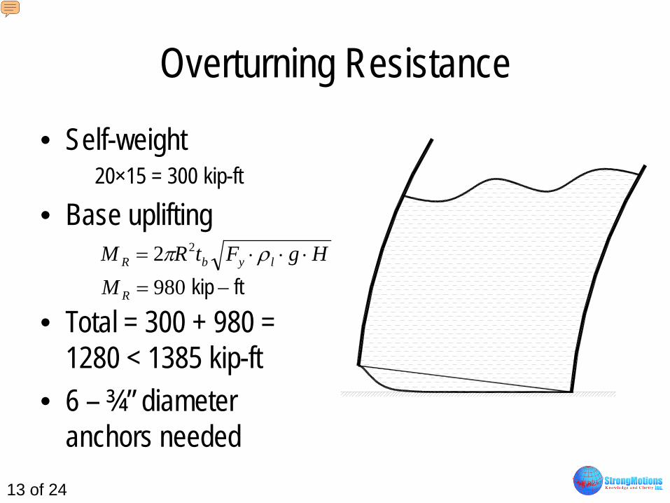
Overturning Resistance
• Self-weight 20×15 = 300 kip-ft
• Base uplifting
• Total = 300 + 980 = 1280 < 1385 kip-ft
• 6 – ¾” diameter anchors needed
HgFtRM lybR ⋅⋅⋅= ρπ 22ftkip −= 980RM
Presenter
Presentation Notes
The stability of the tank against overturning is checked next. A small amount of overturning resistance is provided by the weight of the tank wall and roof. It is obtained by multiplying the weight of the tank wall and roof by the radius of the tank. A more significant amount of overturning resistance is provided by uplifting of the tank base plate. As a portion of the base plate uplifts, the liquid on the uplifted portion provides resistance to overturning. The total overturning resistance from self weight and base uplifting is checked against the design overturning moment. In this case the design overturning moment is greater than the overturning resistance hence six ¾ inch diameter anchors are needed to provide stability against overturning. This also raises several questions: (1) Since anchors are provided to resist the reduced overturning moment, wouldn’t the tank uplift during the design earthquake motion? (2) How much will the tank uplift? (3) Will the anchors be able to accommodate the uplift? (4) What are the values of other critical responses associated with base uplifting: plastic yielding at plate-shell junction; axial compressive stress in tank shell, etc.?
14 of 24
Shortcomings of Traditional Design
• Load reductions due to: (1) period elongation, (2) damping increase, and (3) overstrength are not explicitly computed
• The seismic design performed with ‘artificial’ loads and ‘artificial’ strengths lacks transparency
Presenter
Presentation Notes
The traditional seismic analysis leaves many doubts. It is carried out with judgment-based ‘reduced loads’ and ‘reduced strengths’. Therefore, it lacks transparency. Next we will discuss the performance-based seismic design of tanks.
15 of 24
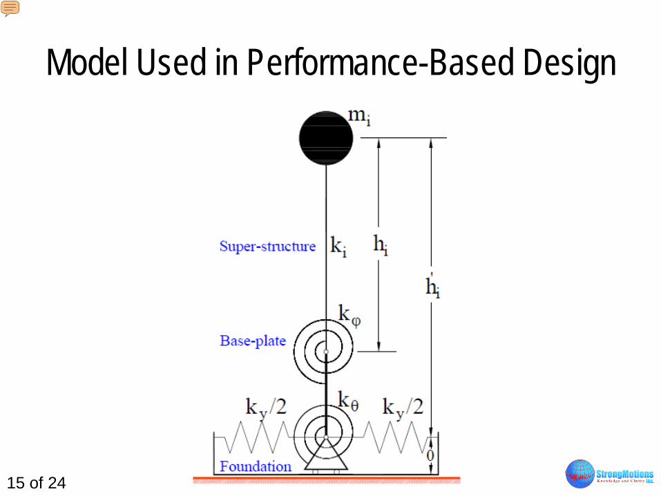
Model Used in Performance-Based Design
Presenter
Presentation Notes
The model used in performance-based seismic design of tanks explicitly considers all sources of flexibility and damping in the tank. The sources of flexibility are: (1) deformation of tank shell; (2) base uplifting; (3) lateral and rotational deformations of the soil below the foundation; and (4) sliding at the base of the tank. The sources of damping are: (1) energy dissipation due to deformation of tank shell; (2) plastic-yielding in the base plate; (3) radiation of waves into the soil below the foundation; and (4) sliding at the base of the tank.
16 of 24
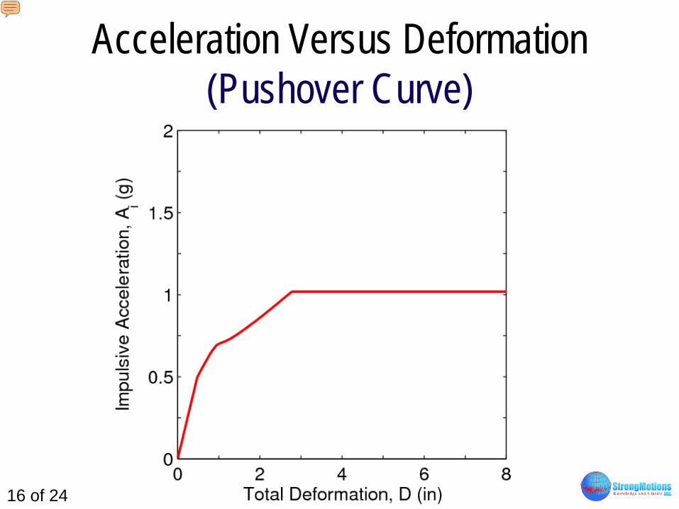
Acceleration Versus Deformation (Pushover Curve)
Presenter
Presentation Notes
A pushover curve is generated by applying an acceleration on the mass (previous slide) and calculating the displacement of the mass (or the deformation of the tank-foundation system). The plot between total deformation D and acceleration A is known as the pushover curve. For small values of acceleration, the tank remains in contact with the foundation and the deformation occurs in the tank shell and foundation. At a certain value of acceleration the tank starts to uplift and the anchors start to yield. This causes a reduction in the slope of the pushover curve or an increase in the flexibility of the tank-foundation system. With further increase in acceleration, the base plate starts to yield causing additional flexibility of the tank-foundation system. At a certain high value of acceleration, the tank starts to slide and the acceleration no longer increases.
17 of 24
Damping Versus Deformation
Presenter
Presentation Notes
The damping changes with increase in the deformation of the tank-foundation system. At low levels of shaking the tank remains bonded to the foundation and foundation damping is the primary source of damping in the system. When the tank starts uplifting the effectiveness of foundation damping reduces because base uplifting becomes the primary source of deformation in the tank. When the base plate starts yielding it contributes slightly to the overall damping. At some point the tank starts sliding and base sliding becomes the dominant source of damping in the system.
18 of 24
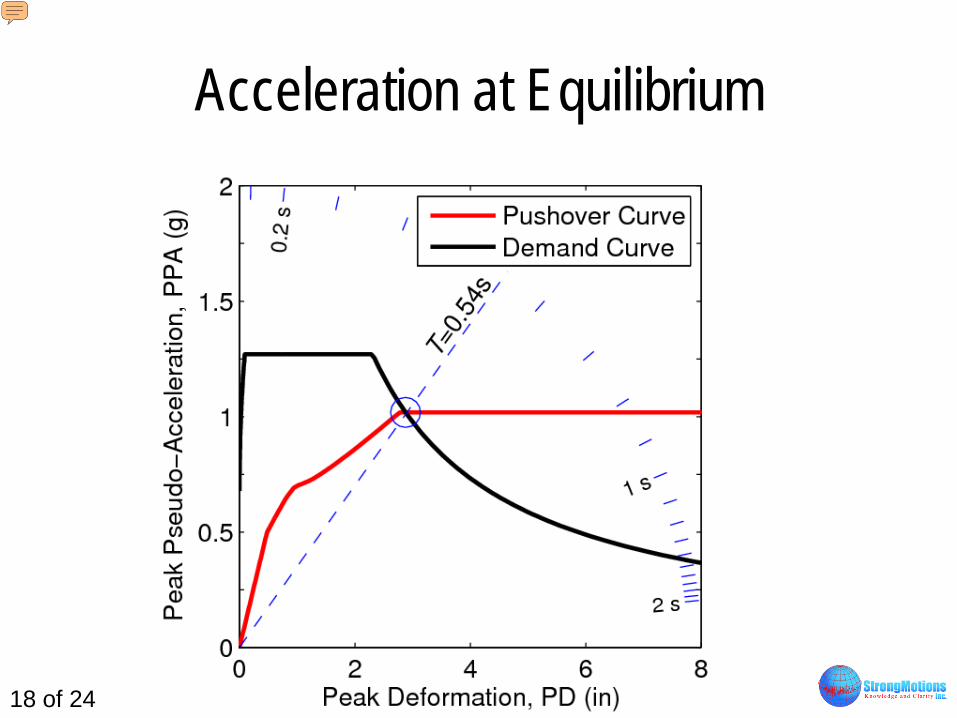
Acceleration at Equilibrium
Presenter
Presentation Notes
By superimposing the pushover curve on demand curve (response spectrum) the equilibrium condition is obtained. The response spectrum (demand curve) is shown in the acceleration-deformation format. Note that the effective period of the system is 0.54 s. This is roughly 7 times the period used in the traditional analysis.
19 of 24
Critical Responses of Tank
Base Uplift = 6.9 in
Plastic Rotation = 38º
Axial Compressive Stress = 7 ksi
Foundation Moment = 1,430 kip-ft
Eurocode limit on plastic rotation = 11.5 º Experiments by Cortés and Nussbaumer (2010) suggest a limit of 23 º
Presenter
Presentation Notes
This slide shows the critical responses of the tank at equilibrium. The tank uplifts by 6.9 in at the base. The plastic rotation at the junction of tank shell and base plate is 38º. The axial compressive stress where the tank shell remains in contact with the foundation is 7 ksi. The overturning moment in the foundation is 1,430 kip-ft. There are a couple of problems with this tank. First, the anchors may not be long enough to accommodate 6.9 in deformation without breaking. Second, the plastic rotation at plate-shell junction is too high. Eurocode allows a plastic rotation of 11.5º. A more recent experimental study suggests that the plastic rotation can reach 23º, but it is still lower than the plastic rotation for this tank. Because of excessive plastic rotation and base uplifting the tank needs base anchors. Next slide shows the effect of anchorage on critical tank responses.
20 of 24
Effect of Increasing Number of Anchors
Response Number of ¾” Diam. Anchors
6 8 10 Base Uplift 6.9 in 5.1 in 3.3 in
Plastic Rotation 38º 31º 22º
Axial Compressive Stress 7 ksi 5.7 ksi 4.6 ksi
Foundation Moment 1,430 kip-ft 1,910 kip-ft 2,400 kip-ft
Presenter
Presentation Notes
By increasing the number of base anchors to 10, the base uplift is reduced to 3.3 in and the plastic rotation is reduced to 22º. Unfortunately the foundation moment has increased to 2,400 kip-ft.
21 of 24
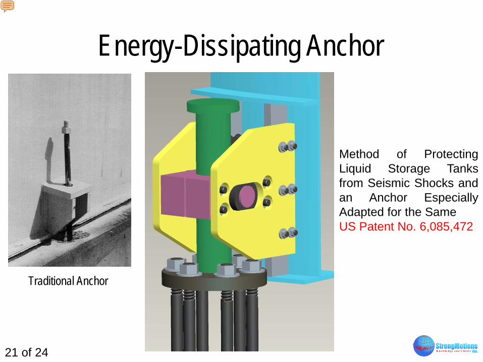
Energy-Dissipating Anchor
Method of Protecting Liquid Storage Tanks from Seismic Shocks and an Anchor Especially Adapted for the Same US Patent No. 6,085,472
Traditional Anchor
Presenter
Presentation Notes
There is another way to anchor the tanks — by use of energy dissipating devices. While a traditional anchor acts only in tension (left side) an energy-dissipating anchors acts both in tension and in compression. A traditional anchor becomes disengaged from the tank after a large uplifting cycle. An energy-dissipating anchor remains fully engaged with the tank at all times.
22 of 24
Idealized Force-Deformation Relationships of Traditional and Energy-Dissipating Anchors
Presenter
Presentation Notes
The uppermost plot is of an applied deformation history on the anchor. The middle plot is of the force history in a traditional anchor. The traditional anchor stretches in the first quarter cycle and remains in its stretched position after that. The energy-dissipating anchor (bottom plot) experiences force reversals and dissipates energy in each cycle.
23 of 24
Comparison
Response 10 Traditional Anchors
6 Energy-Dissipating
Anchors Base Uplift 3.3 in 3.2 in
Plastic Rotation 22º 22º
Axial Compressive Stress 4.6 ksi 4.5 ksi
Foundation Moment 2,400 kip-ft 1,430 kip-ft
Presenter
Presentation Notes
This slide shows a comparison between the responses of a traditionally anchored tank and a tank anchored with energy-dissipating devices. For the same amount of base uplift, plastic rotation and axial compressive stress, a tank with energy-dissipating anchors experiences much smaller foundation moments.
24 of 24
Conclusions
• Performance-based seismic design of tanks can be carried out by using a practical nonlinear analysis
• In many situations, the performance-based seismic design will be more economical than the traditional design
• For the same performance, the seismic design with energy-dissipating anchors will be more economical than a design with traditional anchors
Presenter
Presentation Notes
We learned that performance-based seismic design of tank provides the transparency absent in the traditional (code-based) design. We also learned that performance-based seismic design can be performed in a practical manner. Finally we learned that energy-dissipating anchors reduce the critical responses of the tank without increasing the foundation moments and shears. For a given performance level energy-dissipating anchors provide a cost-effective design of the tank foundation system.