performance analysis of micro blaze implemented … · performance analysis of micro blaze...
TRANSCRIPT

IOSR Journal of Electronics and Communication Engineering (IOSR-JECE)
e-ISSN: 2278-2834,p- ISSN: 2278-8735.Volume 9, Issue 2, Ver. VI (Mar - Apr. 2014), PP 01-13
www.iosrjournals.org
www.iosrjournals.org 1 | Page
Performance Analysis of Micro blaze Implemented GPS-INS
Integrated Systems on Spartan 6 and Zynq FPGAs
B.LokeswaraRao, Associate Professor, Dr.K.V.V.SReddy, Former Professor,
Dr.G.Sasi Bhushana Rao, Professor& HOD Dept. of ECE, BIET, Hyderabad, A.P, INDIA
Dept. of ECE, Andhra University College of Engineering (A), Visakhapatnam, A.P, INDIA
Dept. of ECE, Andhra University College of Engineering (A), Visakhapatnam, A.P, INDIA
Abstract: This paper compares the performances of two loosely coupled Micro blaze Implemented
GPS-INS Integrated Systems On Spartan 6 And Zynq FPGAs. The first system usesa Micro blaze
implemented GPS-INS integrated system on Spartan 6 Field Programmable Gate Array (FPGA) for
inertial navigation solution and Kalman filter computation.The second system uses a Micro blaze
implemented GPS-INS integrated system on Zynq FPGA for inertial navigation solution and Kalman
filter computation . Real time issues related to accuracy of position, GPS outages, Selective availability of
GPS, Higher variances of accelerometers, Resource usage of FPGA in terms of Slices, DSP48 and Block
Random Access Memory (BRAM), Computation time, latency, and power consumption are presented.The
systems are designed to give real time processed navigation solutions with an update rate of 100 Hz.
Key words:Global positioning system,Inertial navigation system,Kalman filter ,Spartan 6 FPGA,Zynq
FPGA.
I. Introduction MEMS-based Inertial Measurement Unit(IMU) systems have proved to be highly popular and
feasible for autonomous navigation systems[1-9].These systems are cost effective,compact and light
weight.They do not have good precision.
A loosely coupled integrated approach [1,4] using a GPS receiver and alow cost strap down INS,
is used to overcome the sensor errors or random disturbances.Many papers have reported the
processing of the GPS INS signalsoffline[7].The inertial navigation computation is performed at
100Hz.Thisinertial datais then integrated with the GPS data at 1 Hz[10].
Coupling of low cost inertial sensors with GPS is broadly classified as Loosely coupled system ,
Tightly coupled system and Ultra-tightly coupled system.
Fig.1.Loosely Coupled Integrated GPS-INS System
a) Loosely coupled system: In this system GPS
data, i.e., position, velocity, etc. are coupled with INS data using an Extended Kalman Filter( EKF) as shown in
Fig. 1. It is highly dependent on the availability of GPS data. In the present work, a nine state Kalman filter is
used.
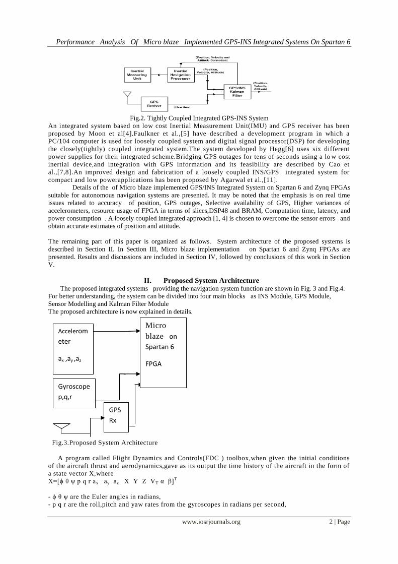
b) Tightly coupled system: In this system, the
INS data is directly fused with GPS raw measurement data inside the GPS Kalman filter as shown in Fig.2. It is
more robust compared with the loosely coupled system. However, it is also more complex.
c) Ultra-tightly coupled system
This type of integration method requires access to the receiver’s firmware. As a result, this scheme of
integration is usually implemented only by the equipment manufacturer.
Performance Analysis Of Micro blaze Implemented GPS-INS Integrated Systems On Spartan 6
www.iosrjournals.org 2 | Page
Fig.2. Tightly Coupled Integrated GPS-INS System
An integrated system based on low cost Inertial Measurement Unit(IMU) and GPS receiver has been
proposed by Moon et al[4].Faulkner et al.,[5] have described a development program in which a
PC/104 computer is used for loosely coupled system and digital signal processor(DSP) for developing
the closely(tightly) coupled integrated system.The system developed by Hegg[6] uses six different
power supplies for their integrated scheme.Bridging GPS outages for tens of seconds using a lo w cost
inertial device,and integration with GPS information and its feasibility are described by Cao et
al.,[7,8].An improved design and fabrication of a loosely coupled INS/GPS integrated system for
compact and low powerapplications has been proposed by Agarwal et al.,[11].
Details of the of Micro blaze implemented GPS/INS Integrated System on Spartan 6 and Zynq FPGAs
suitable for autonomous navigation systems are presented. It may be noted that the emphasis is on real time
issues related to accuracy of position, GPS outages, Selective availability of GPS, Higher variances of
accelerometers, resource usage of FPGA in terms of slices,DSP48 and BRAM, Computation time, latency, and
power consumption . A loosely coupled integrated approach [1, 4] is chosen to overcome the sensor errors and
obtain accurate estimates of position and attitude.
The remaining part of this paper is organized as follows. System architecture of the proposed systems is
described in Section II. In Section III, Micro blaze implementation on Spartan 6 and Zynq FPGAs are
presented. Results and discussions are included in Section IV, followed by conclusions of this work in Section
V.
II. Proposed System Architecture The proposed integrated systems providing the navigation system function are shown in Fig. 3 and Fig.4.
For better understanding, the system can be divided into four main blocks as INS Module, GPS Module,
Sensor Modelling and Kalman Filter Module
The proposed architecture is now explained in details.
Fig.3.Proposed System Architecture
A program called Flight Dynamics and Controls(FDC ) toolbox,when given the initial conditions
of the aircraft thrust and aerodynamics,gave as its output the time history of the aircraft in the form of
a state vector X,where
X=[ϕ θ ψ p q r ax ay az X Y Z VT α β]T
- ϕ θ ψ are the Euler angles in radians,
- p q r are the roll,pitch and yaw rates from the gyroscopes in radians per second,
GPS
Rx
Accelerom
eter
ax ,ay ,az
Gyroscope
p,q,r
Micro
blaze on
Spartan 6
FPGA

Performance Analysis Of Micro blaze Implemented GPS-INS Integrated Systems On Spartan 6
www.iosrjournals.org 3 | Page
- ax ay az are the accelerations from the accelorometers in m/s2 ,
-X Y Z are the distances along the three axes in the navigation frame in meters,
- VT α β are the velocity of the aircraft in m/s,the angle of attack in radians and the sideslip angle in
radians,respectively.
Fig.4.Proposed System Architecture
The FDC program can generate these values at any time step as required.Typical time steps or update
rates range from 10ms-100ms.
2.1.INS Module
The INS program now takes 6 states from this time history,viz.p,q,r, ax , ay , az.These act as if
the program is reading directly from the gyros and accelerometers.Then the program integrates and
calculates four Euler parameters.From these Euler parameters,the Euler angles are calculated.Now the
accelerations from the accelerometers are used to get the values of U,V,W.
We now have the velocity components of the aircraft in the body frame.To convert it to the navigation
frame or local earth frame,we use the DCM matrix and calculate VT .
These velocity components are then integrated to get the position X,Y,Z along the three axes in the
local earth frame.The latitude,longitude and height can be calculated.All the integrations are carried
out using the fourth order Runge-Kutta methods.The INS Module is shown in Fig.5.
p
q
r
ay
az
ax
Fli
gh
t
dy
na
mi
cs
&
co
nt
ro
l
Euler
parameter
integration
Gravitati
on &
centrifug
al
correctio
n
Euler angle
computation
U,V,W
integratio
n
DCM
VN,V
E,VD
calc
ulat
ion
Latitud
e,Longit
ude,Alti
tude
integrat
ion
Φ θ ψ
λ
μ
H
Fig.5.INS Module
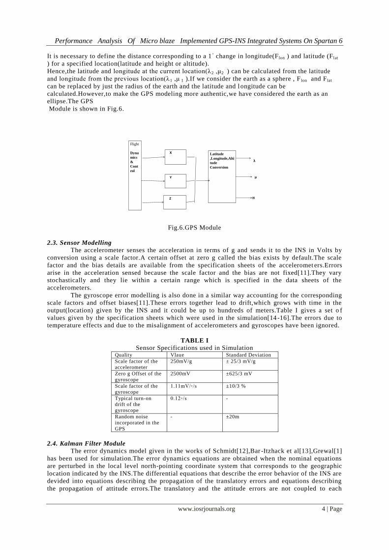
2.2.GPS Module
The GPS gives the latitude,longitude and altitude of the current location the receiver.What our
program does is that it converts the X,Y,Z given out by the FDC into latitude,longitude and altitude as
would be given out by the GPS receiver.The update rate is 1 second.The GPS program uses WGS -84
approximatio in which the earth is considered as an ellipse with a semi -major axis(equatorial radius)
of a=6,378,137m,and a semi-minor axis(polar radius) of b=6,356,752.3142m.
GPS
Rx
Accelerom
eter
ax ,ay ,az
Gyroscope
p,q,r
Micro
blaze on
Zynq FPGA
Performance Analysis Of Micro blaze Implemented GPS-INS Integrated Systems On Spartan 6
www.iosrjournals.org 4 | Page
It is necessary to define the distance corresponding to a 1◦ change in longitude(F lon ) and latitude (Flat
) for a specified location(latitude and height or altitude).
Hence,the latitude and longitude at the current location(λ2 ,μ2 ) can be calculated from the latitude
and longitude from the previous location(λ1 ,μ 1 ).If we consider the earth as a sphere , F lon and Flat
can be replaced by just the radius of the earth and the latitude and longitude can be
calculated.However,to make the GPS modeling more authentic,we have considered the earth as an
ellipse.The GPS
Module is shown in Fig.6.
Flight
Dyna
mics
&
Cont
rol
X
Y
Z
Latitude
,Longitude,Alti
tude
Conversion
λ
μ
H
Fig.6.GPS Module
2.3. Sensor Modelling
The accelerometer senses the acceleration in terms of g and sends it to the INS in Volts by
conversion using a scale factor.A certain offset at zero g called the bias exists by default.The scale
factor and the bias details are available from the specification sheets of the acceleromet ers.Errors
arise in the acceleration sensed because the scale factor and the bias are not fixed[11].They vary
stochastically and they lie within a certain range which is specified in the data sheets of the
accelerometers.
The gyroscope error modelling is also done in a similar way accounting for the corresponding
scale factors and offset biases[11].These errors together lead to drift,which grows with time in the
output(location) given by the INS and it could be up to hundreds of meters.Table I gives a set o f
values given by the specification sheets which were used in the simulation[14 -16].The errors due to
temperature effects and due to the misalignment of accelerometers and gyroscopes have been ignored.
TABLE I
Sensor Specifications used in Simulation Quality Vlaue Standard Deviation
Scale factor of the accelerometer
250mV/g ± 25/3 mV/g
Zero g Offset of the
gyroscope
2500mV ±625/3 mV
Scale factor of the gyroscope
1.11mV/◦/s ±10/3 %
Typical turn-on
drift of the gyroscope
0.12◦/s -
Random noise
incorporated in the
GPS
- ±20m
2.4. Kalman Filter Module
The error dynamics model given in the works of Schmidt[12],Bar -Itzhack et al[13],Grewal[1]
has been used for simulation.The error dynamics equations are obtained when the nominal equations
are perturbed in the local level north-pointing coordinate system that corresponds to the geographic
location indicated by the INS.The differential equations that describe the error behavior of the INS are
devided into equations describing the propagation of the translatory errors and equations describing
the propagation of attitude errors.The translatory and the attitude errors are not coupled to each
Performance Analysis Of Micro blaze Implemented GPS-INS Integrated Systems On Spartan 6
www.iosrjournals.org 5 | Page
other.The nine state INS/GPS integration Kalman filter will then be built using the error dynamics
equations.The Kalman Filter Module is shown in Fig.7.
The Micro blaze implementation of the prototype
integrated GPS/INS systems on Spartan 6 and Zynq FPGAs are discussed in detail in the next section.
ERROR IMPLEMENTATION
p
q
r
ay
az
ax
Flight dynamics & control
Euler parameter integration
Gravitation & centrifugal correction
Euler angle computation
U,V,Wintegration
DCM
VN,VE,VD
calculation
Latitude,Longitude,Altitudeintegration
Φ θ ψ
λ
μ
H
Kalman filterμ
H
λ
Corrected position
Fig.7.Kalman Filter Module
III. Implementation With Micro Blaze This section describes about the Micro blaze implemented GPS-INS integrated systems on Spartan 6
and ZynqFPGAs .
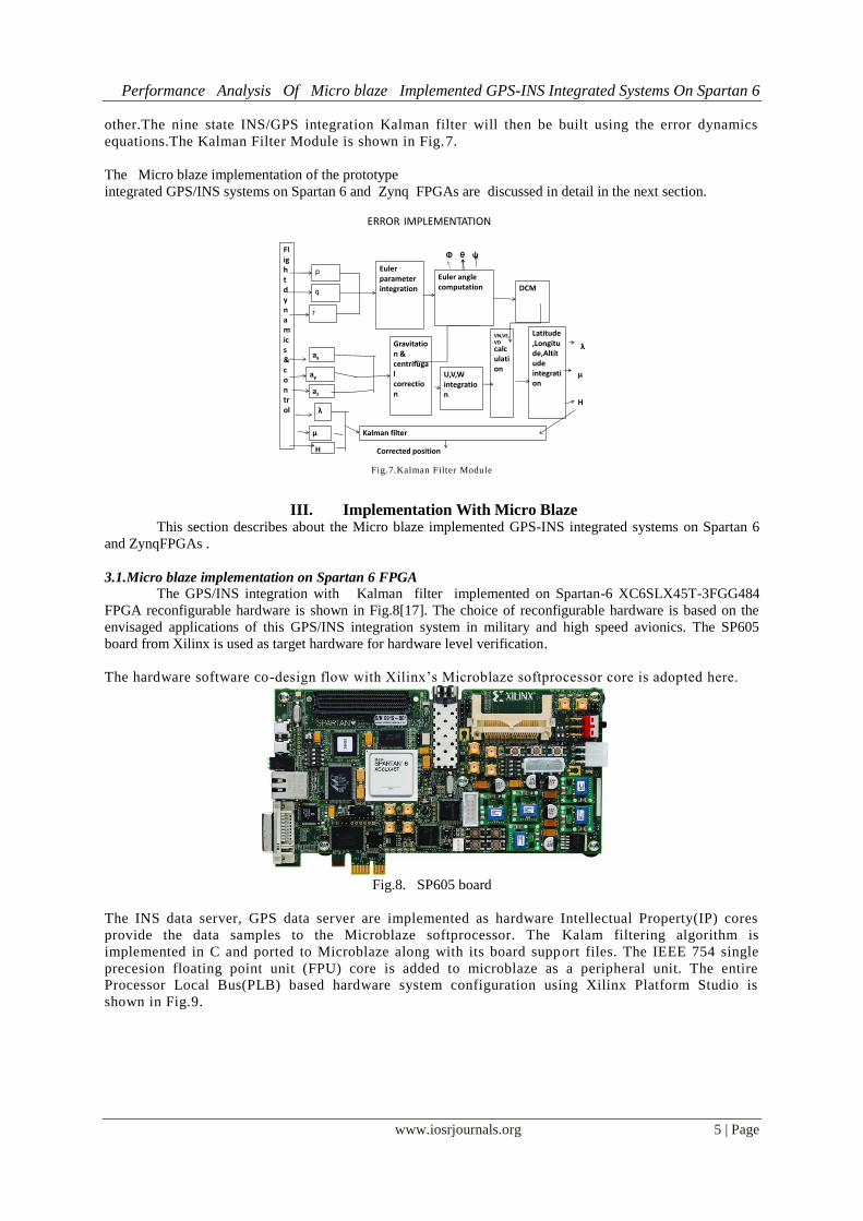
3.1.Micro blaze implementation on Spartan 6 FPGA
The GPS/INS integration with Kalman filter implemented on Spartan-6 XC6SLX45T-3FGG484
FPGA reconfigurable hardware is shown in Fig.8[17]. The choice of reconfigurable hardware is based on the
envisaged applications of this GPS/INS integration system in military and high speed avionics. The SP605
board from Xilinx is used as target hardware for hardware level verification.
The hardware software co-design flow with Xilinx’s Microblaze softprocessor core is adopted here.
Fig.8. SP605 board
The INS data server, GPS data server are implemented as hardware Intellectual Property(IP) cores
provide the data samples to the Microblaze softprocessor. The Kalam filtering algorithm is
implemented in C and ported to Microblaze along with its board support files. The IEEE 754 single
precesion floating point unit (FPU) core is added to microblaze as a peripheral unit. The entire
Processor Local Bus(PLB) based hardware system configuration using Xilinx Platform Studio is
shown in Fig.9.
Performance Analysis Of Micro blaze Implemented GPS-INS Integrated Systems On Spartan 6
www.iosrjournals.org 6 | Page
Fig.9. Hardware plat form with Micro blaze and peripherals
The USB-UART available on board is used for reading the algorithm inputs and outputs to personal computer
(PC) for further analysis. The onboard JTAG debugger is used for configuration and runtime debugging.
MATLAB is used for analyzing the logged data and results are presented in next section.
3.2. Micro blaze implementation onZynq FPGA
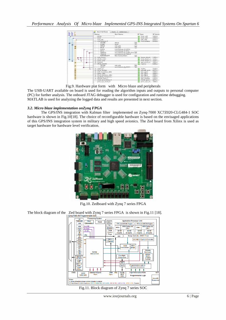
The GPS/INS integration with Kalman filter implemented on Zynq-7000 XC7Z020-CLG484-1 SOC
hardware is shown in Fig.10[18]. The choice of reconfigurable hardware is based on the envisaged applications
of this GPS/INS integration system in military and high speed avionics. The Zed board from Xilinx is used as
target hardware for hardware level verification.
Fig.10. Zedboard with Zynq 7 series FPGA
The block diagram of the Zed board with Zynq 7 series FPGA is shown in Fig.11 [18].
Fig.11. Block diagram of Zynq 7 series SOC

Performance Analysis Of Micro blaze Implemented GPS-INS Integrated Systems On Spartan 6
www.iosrjournals.org 7 | Page
The hardware software co-design flow with Xilinx’s Zynq’s ARM-9 hardcore processor core is
adopted here. The INS data server, GPS data server are implemented as hardware IP cores provide the
data samples to the ARM-9 processor. The Kalman filtering algorithm is implemented in C and ported
to ARM-9 along with its board support files. The IEEE 754 single precesion floating point unit (FPU)
core is enabled. The entire AXI bus based hardware system configure using Xilinx Platform Studio is
shown in Fig.12[17].
Fig.12.Hardware platform with ZYNQ and peripherals
The USB-UART available on board is used for reading the algorithm inputs and outputs to personal computer
(PC) for further analysis. The onboard JTAG debugger is used for configuration and runtime debugging.
MATLAB is used for analyzing the logged data and results are presented in next section.
IV. Results And Discussions Input for the system is read from the data stored on the hard drive and the program is run just as if the
collection (of data) was taking place in real-time. The simulated sensor data are generated using trajectories
obtained from flight dynamic and control tool box (FDC) in MATLAB. Aircraft states were stored to simulate
sensors. To analyze the prediction accuracy of INS, it was compared with a true trajectory generated using
MATLAB. Simulated results include various errors in inertial sensors and the GPS. Same sensor outputs were
given to the present Micro blaze implementation on Spartan 6 FPGA and the results were compared. The
output waveforms obtained from the unaided INS , GPS and actual trajectory are shown in Figs.13-15. The
output waveforms obtained from the integrated GPS-INS system , the GPS, ,and the actual trajectory are shown
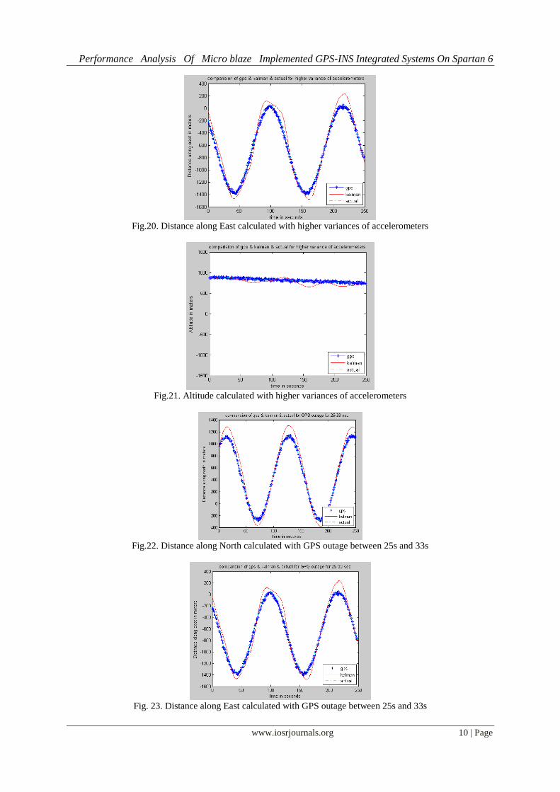
in Figs.15-17. Trajectory plots showing usage of higher variance of accelerometers are shown in Figs.18-20.
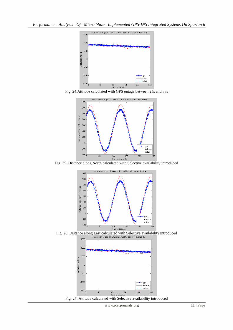
Trajectory plots showing a GPS “outage”, are shown in Figs.21-23. Trajectory plots showing Selective
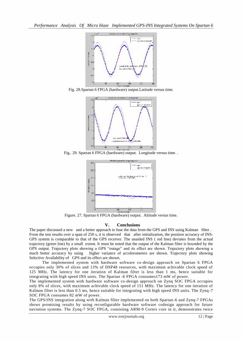
Availability of GPS are shown in Figs.24-26. The plots for latitude, longitude, and altitude obtained directly
from the hardware (Micro blaze implemented on Spartan 6 FPGA output) are shown in Figs. 27-29. The plots
for latitude, longitude, and altitude obtained directly from the hardware (Micro blaze implemented on Zynq
FPGA output) are also the same as the plots shown in Figs. 27-29.They show good agreement with the actual
trajectory.
The resource utiliation report of developed system on Spartan-6 FPGA are given in Table II. As
the area consuming algorithm blocks are implemented on Microblaze and performance demanding
blocks are implemented on FPGA fabrics, the implemented system demonstrates optimal area
occupancy and high speed implementation.
TABLE II
Resource Utiliation Resource Total available Used % utilization
Slice Registers 54,576 7,293 13%
Slice LUTs 27,288 8,429 30%
BRAM 116 31 21%
DSP48 58 8 13%
The maximum clock speed achieved by Microblaze softprocessor is 125 MHz. The present system is
tested at 88 MHz clock speed. The FPGA running total integration system is profiled for speed and
latencies by running for 900 seconds of data.The Kalman filter iterations are presently being
computed at 10 ms interval. However the implemented logic is able to achieve the latency of 0.9 ms
for every iteration. Hence the present system can integrate with INS system with update rate of 1 ms.
The resource utiliation report of developed system on Zynq SOC FPGA is given in Table III. As the
area consuming algorithm blocks are implemented on ARM-9 Cortex and performance demanding

Performance Analysis Of Micro blaze Implemented GPS-INS Integrated Systems On Spartan 6
www.iosrjournals.org 8 | Page
blocks are implemented on FPGA fabrics, the implemented system demonstrates optimal area
occupancy and high speed implementation. Note that as the ARM-9 Cortex has hard core processor,
no BRAM and DSP48 slices will be consumed from FPGA fabrics.
TABLE III
Resource Utiliation Resource Total available Used % utilization
Slice Registers 106,400 2080 2%
Slice LUTs 53,200 4,159 8%
BRAM 140 0 0%
DSP48 220 0 0%
The maximum clock speed achieved by RTL logic is 151 MHz. The FPGA running total integration
system is profiled for speed and latencies by running for 900 seconds of data.
The Kalman filter iterations are presently being computed at 10 ms interval. However the
implemented logic is able to achieve the latency of 0.41 ms for every iteration. Hence even the present
system can integrate with INS system with update rate of 0.5 ms .
Fig. 13. Distance along North calculated by unaided INS and GPS
Fig. 14. Distance along East calculated by unaided INS and GPS
Fig. 15. Altitude along East calculated by unaided INS and GPS

Performance Analysis Of Micro blaze Implemented GPS-INS Integrated Systems On Spartan 6
www.iosrjournals.org 9 | Page
Fig. 16.Kalman filtered output of distance along North
Fig. 17.Kalman filtered output of distance along East
Fig. 18.Kalman filtered output of Altitude
Fig. 19. Distance along North calculated with higher variances of accelerometers
Performance Analysis Of Micro blaze Implemented GPS-INS Integrated Systems On Spartan 6
www.iosrjournals.org 10 | Page
Fig.20. Distance along East calculated with higher variances of accelerometers
Fig.21. Altitude calculated with higher variances of accelerometers
Fig.22. Distance along North calculated with GPS outage between 25s and 33s
Fig. 23. Distance along East calculated with GPS outage between 25s and 33s
Performance Analysis Of Micro blaze Implemented GPS-INS Integrated Systems On Spartan 6
www.iosrjournals.org 11 | Page
Fig. 24.Attitude calculated with GPS outage between 25s and 33s
Fig. 25. Distance along North calculated with Selective availability introduced
Fig. 26. Distance along East calculated with Selective availability introduced
Fig. 27. Attitude calculated with Selective availability introduced
Performance Analysis Of Micro blaze Implemented GPS-INS Integrated Systems On Spartan 6
www.iosrjournals.org 12 | Page
Fig. 28.Spartan 6 FPGA (hardware) output.Latitude versus time.
Fig.. 29. Spartan 6 FPGA (hardware) output. Longitude versus time. .
Figure. 27. Spartan 6 FPGA (hardware) output. Altitude versus time.
V. Conclusions The paper discussed a new and a better approach to fuse the data from the GPS and INS using Kalman filter .
From the test results over a span of 250 s, it is observed that after initialization, the position accuracy of INS-
GPS system is comparable to that of the GPS receiver. The unaided INS ( red line) deviates from the actual
trajectory (green line) by a small extent. It must be noted that the output of the Kalman filter is bounded by the
GPS output. Trajectory plots showing a GPS “outage” and its effect are shown. Trajectory plots showing a
much better accuracy by using higher variance of accelerometers are shown. Trajectory plots showing
Selective Availability of GPS and its effect are shown.
The implemented system with hardware software co-design approach on Spartan 6 FPGA
occupies only 30% of slices and 13% of DSP48 resources, with maximum achivable clock speed of
125 MHz. The latency for one iteration of Kalman filter is less than 1 ms, hence suitable for
integrating with high speed INS units. The Spartan -6 FPGA consumes173 mW of power.
The implemented system with hardware software co-design approach on Zynq SOC FPGA occupies
only 8% of slices, with maximum achivable clock speed of 151 MHz. The latency for one iteration of
Kalman filter is less than 0.5 ms, hence suitable for integrating with high speed INS units. The Zynq -7
SOC FPGA consumes 82 mW of power.
The GPS/INS integration along with Kalman filter implemented on both Spartan -6 and Zynq-7 FPGAs
shows promising results by using reconfigurable hardware software codesign approach for future
naviation systems. The Zynq-7 SOC FPGA, consisting ARM-9 Cortex core in it, demonstrates twice
Performance Analysis Of Micro blaze Implemented GPS-INS Integrated Systems On Spartan 6
www.iosrjournals.org 13 | Page
the higher speed while consuming only half of the power in comparison with spartan -6 FPGA. The
Zynq based implementation also proven to be area efficient by occupying only 8% of resouces in
comparison with Spartan-6 implemenation occupying 30% of resouces.
However the spartan-6 FPGA softcore implementation creates opportunity for multicore
instantiation and hence parallel Kalman filter execution for even complex GPS/INS integration
algorithms.
References [1] Grewal, M. S., Weill, L. R., and Andrews, A. P. Global Positioning Systems. Inertial Navigation, and Integration. New York:
Wiley, 2001.
[2] Sukkarieh, S., Nebot, E. M., and Durrant-Whyte, H. F. A high integrity IMU/GPS navigation loop for autonomousland vehicle applications. IEEE Transactions on Robotics and Automation, 15, 3 (June 1999), 572—578.
[3] Shang, J., Mao, G., and Gu, Q. T.Design and implementation of MIMU/GPS integrated navigation systems.In IEEE Position
Location and Navigation Symposium,Apr. 2002, 99—105. [4] Moon, S. W., Hwang, D. H., Sung, T. K., and Lee, S. J. Design and Implementation of an Efficient Loosely-Coupled GPS/INS
integration scheme.Technical Report, Chungnam National University, Korea,1998.
[5] Faulkner,N.M.,Cooper, S,J., and Jeary, P.A.Integrated MEMS/GPS navigation systems, In IEEE Position Location and Navigation Symposium April 2002, 306-313.
[6] Hegg.J.Enhanced space integrated GPS/INS(SIGI)IEEE Aerospace and Electronic systems Magazine, 17, 4. April 2002, 26-33.
[7] Cao, F.X., Yang, D.K., Xu, A.G., Ma, J., Xiao, W.D., Law, C.L., Ling, K.V., and Chua, H.C.Low cost SINS/GPS integration for land vehicle navigation.In IEEE 5th International Conference on Intelligent Transportation Systems, Sept. 2002, 910-913.
[8] Jaffe, R., Qi, H., Carter, P., and Madni, A.M.MMQ-G, A low cost MEMS INS-GPS. In ION GNSS 18th International Technical
Meeting of the Satellite Division, Long Beach, CA, Sept 13-16, 2005, 956-966. [9] Lichuan L., Zengshan, T., and Shun-ji, H.An algorithm for integrating GPS/INS attitude determination system In CIE International
Conference on Radar, 2001. 167-170.
[10] Qi.H.m, and Moore, J.B.DirectKalman filtering approach for GPS/INS integration IEEE Transactions on Aerospace and Electronic Systems, 38, 2 (Apr. 2002), 687-693.
[11] Agarwal.V.,Arya .H.,andBhaktavatsala.S.Design and Development of a Real-time DSP and FPGA-Based Integrated GPS-INS
System for Compact and Low Power Applications. In IEEE Transactions on Aerospace and Electronic Systems, 45, 2(Apr.2009) 443-454.
[12] Schmidt,G.T., “Strapdown Inertial Systems-Theory and Applications”,AGARD Lecture Series,No.95,1978
[13] Bar-Itzhack,I.Y.,andBerman,N., “Control Theoretic Approach to Inertial Navigation Systems,”Journal of Guidance,Vol.11,No.3,1988,pp.237-245.
[14] ADXL212 Analog Devices, datasheet.http://www.analog.com/UploadedFiles/Data Sheets/accessed 2013.
[15] DXRS652 Analog Devices, datasheet.http://www.analog.com/UploadedFiles/Data Sheets/; accessed 2013. [16] GPS-Receiver JP3 Falcom Wireless Communication, users manual, www.falcom; accessed 2013.
[17] http://www.Xylinx.com; accessed 2013.
[18] ] http://www.Zedboard.org; accessed 2013.
BhogadiLokeswaraRao was born on Jan 4,1968.He received his Bachelor’s degree in Electronics &
Communication Engineering fromAndhra University, and Master’s degree in Microwave & Radar
Engineering from Osmania University. He is currently an Associate Professor in the Department of
Electronics & Communication Engineering, Bharat Institute of Engineering & Technology , Hyderabad
and is also pursuing Ph.D from Andhra University . He has 24 years of experience in Teaching, R&D, and
Industry. He is working in the area of GPS/INS Integration using Kalman filtering using FPGAs. He is a
Fellow of IETE and also a Fellow of IE (India).
Prof.KVVS Reddy was born on August 14, 1951. He posseses B.E., M.E., and Ph.D degrees. He woked as a
Professor in the Department of Electronics & Communication Engineering of College of Engineering,
Andhra University, Visakhapatnam for more than 32 years..He also worked in ECIL, Hyderabad for three
years before joining AU. Under his guidance 10 Ph.Ds are awarded and few more are pursuing their Ph.Ds.
His research interests are in Mobile communication, DSP, Navigation, Radar and Microwave.
Prof.G.SasibhushanaRao was born on August 15, 1964. He posseses B.E., M.E., Ph.D and
MBA(HRD&Mkting) degrees. He is currently working as Professor & HOD in the Department of
Electronics & Communication Engineering of College of Engineering, Andhra University, Visakhapatnam.
He has 28 years of experience in Teaching, R&D, and Industry. Under his guidance 7 Ph.Ds are awarded and
few more are pursuing their Ph.Ds.. His research interests are in Navigation, GPS Signal processing, Radar
and Microwave. He is a Senior Member of IEEE, USA, Fellow of IETE, Member of International GNSS
Society,Australia,,Member of IEEE Comm.Society, USA,Permanent Member of Indian Geophysical Union(IGU),NGRI and
Chartered Engineer for IETE .He has published 290 research papers in various International/National Journals/Conferences
including IEEE.He is a Reviewer for IEEE, IETE, Indian Academic Journals and other International Journals. He received
Dr.SurvepalliRadhakrishnan Award for Best Academician and also Best Researcher Award from Andhra University. He
published 3 text books on GPS, Cellular & Mobile Communications and Electromagnetic Field Theory & Transmission
Lines from Mc-GraHill Publications, New Delhi, Pearson International, New Delhi and John Wiley & Sons respectively.