performance analysis of downlink power control algorithms for cdma systems
DESCRIPTION
Performance Analysis of Downlink Power Control Algorithms for CDMA Systems. Soumya Das Sachin Ganu Natalia Rivera Ritabrata Roy. Outline. Introduction Power Control Advantages Strategies Algorithms Simulation Setup PC Algorithms Comparison Future Work. Introduction. - PowerPoint PPT PresentationTRANSCRIPT

Performance Analysis of Downlink Power Control Algorithms for CDMA Systems
Soumya DasSachin GanuNatalia RiveraRitabrata Roy

Outline Introduction Power Control
Advantages Strategies
Algorithms Simulation Setup PC Algorithms
Comparison Future Work

Introduction
CDMA is a multiple access technique used in cdmaOne, CDMA2000, 1xEV-DO, 1xEV-DV and UMTS

Properties of CDMA Protection against delay spread greater
than one chip RAKE receiver Power Control Algorithms Intracell Interference Voice Activity Factor Soft Degradation Sectorization Capacity Gain

MS1
MS2
d
12
1
21
R
R
RR
P
P
I
C
PP
P
f1.25 MHz
1RP
2RP
1TP
2TP
Ideal CDMA System
MS1
MS2
d
16
116
1
2/
1
2
1
21
142
R
R
RR
RR
P
P
I
C
PP
Pd
P
P
f1.25 MHz
12 16 RR PP
1TP
2TP
d/2
Near-Far Effect

What is Power Control?
Power control refers to the strategies or techniques required in order to adjust, correct and manage the power from the BS/MS in both directions (i.e. uplink and downlink) in an efficient manner.

Other advantages of PC
1. Maintain a satisfactory voice quality for most users
2. Increase overall system capacity while meeting QoS requirements
3. Reduce the average transmit power from mobiles or from cells and sectors
4. Maintain performance objectives such as BER, FER, capacity estimates, dropped-call rate and overall coverage capacity.

PC Strategies UPLINK (Reverse Link) PC
Controls the mobile’s transmit power
Open-Loop PCMobile measures received power and adjusts its transmit power accordingly. (Note: 85dB dynamic range, rapid response is in sec)
Closed-Loop PCBS measures received power from all mobiles and simultaneously commands the individual mobiles to raise or lower transmit uplink power so that the received SNR from all MSs at the BS is the same (800 commands/sec, + 1dB)
Closed Outer-loop PC Closed Inner-loop PC

DOWNLINK (Forward Link) PCBase station periodically reduces transmit power (0.5 dB every 15-20 ms) to mobile until mobile senses increasing error rate. (Note: Dynamic range is about 6 dB around nominal transmit power)
PC Strategies (cont.)

PC Strategies (contd) Intracell Interference
Undesired CDMA signals appear as noise at the receiver output With PC, the equivalent Eb/N0 for CDMA receiver is given by
c
b
eq
b
EMN
E
N
E
)1(0,0
c
b
c
b
eq
b
RPM
RP
EM
E
N
E
/)1(
/
)1(,0
Processing Gainb
c
eq
b
R
R
MN
E
)1(
1
,0

PC algorithms studied
Distance Based Power Allocation Distributed Balancing Power Control Multiple step SIR based power control
with fixed step size Adaptive Step Power Control Modified Adaptive Step Power Control
(with buffer)

Simulation setup Characteristic of each forward link is
independent and identical Fixed number of mobiles per cell Mobiles are uniformly located within
the cell All mobiles are listening at all times Effect of shadow fading (lognormal
distribution) and path loss have been considered
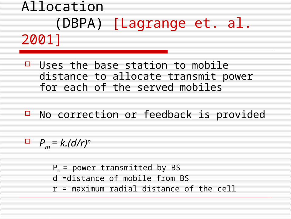
1. Distance Based Power Allocation (DBPA) [Lagrange et. al. 2001]
Uses the base station to mobile distance to allocate transmit power for each of the served mobiles
No correction or feedback is provided
Pm = k.(d/r)n
Pm = power transmitted by BSd =distance of mobile from BSr = maximum radial distance of the cell

DBPA – outage probability vs. number of users

2. Distributed Balancing Algorithm (DB) [Chang, Ren 1994]
Calculates the optimal transmit power assignment for each mobile within the cell, taking into consideration all the neighboring cells
The optimal transmit power assignment for a mobile is proportional to the ratio of the total received power of the mobile to the link gain between its base station and itself
Gives the best achievable performance, but it is relatively difficult to implement

Distributed Balancing – outage probability vs. number of users

3. Multiple Step SIR based power control (MSPC)[Chang,Ren 1994]
Closed-loop control (uses feedback from the mobile to adjust the transmitted power of the base station)
Mobile station measures SIR_obs over a certain period and compares with SIR_threshold
If SIR_obs > SIR_threshold the mobile sends a power-down command, otherwise sends a power-up command to base station
Base station updates its transmitted power for the mobile based on the power-up/down commands
PC updates usually take place in multiple fixed-size steps

MSPC Flowchart

MSPC- outage probability vs. number of iterations

4. Adaptive Step Power Control (ASPC) [Lagrange et. al. 2002]
Uses adaptive step sizes to achieve faster convergence
Step size depends on the previous state If one power-up/down command, the step
is delta. If two or more consecutive power-up
commands, the step size is mu*delta If two or more consecutive power-down
commands, the step size is nu*delta

ASPC Flowchart

ASPC – outage probability vs. number of iterations

5. Modified Adaptive Step Power Control (M-ASPC)
Modification of ASPC algorithm to do away with the small oscillations in outage probability versus number of iterations plot
Introduction of two SIR_thresholds (lower and upper critical thresholds) in place of a single threshold
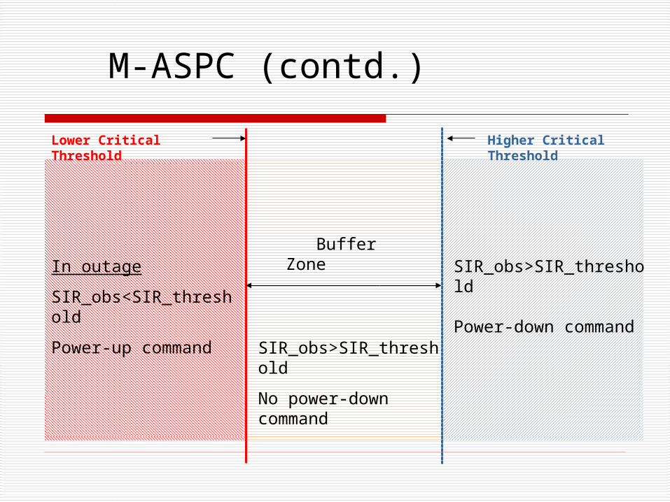
Buffer ZoneIn outage
SIR_obs<SIR_threshold
Power-up command
SIR_obs>SIR_threshold
Power-down command SIR_obs>SIR_threshold
No power-down command
M-ASPC (contd.)
Lower Critical Threshold Higher Critical Threshold

M-ASPC - outage probability vs. number of iterations

Performance Comparison of Power Control Algorithms

DBPA and DB – outage probability vs. number of mobiles

FSPC, ASPC, M-ASPC with buffer outage prob. vs. no. of iterations

FSPC, ASPC and M-ASPC outage prob. vs. no. of mobiles

Future Work
Performance with mobiles moving in and out of the cell (i.e. handoff)
Performance with admission control (i.e. call-blocking)
Extension of M-ASPC to multi-cell scenarios