performance analysis of double tuned passive filter for ... · performance analysis of double tuned...
TRANSCRIPT

American Journal of Engineering and Technology Research Vol. 16, No.2, 2016
1
Performance Analysis of Double Tuned Passive Filter for Power Quality
Kumar Reddy Cheepati Dr.Sardar Ali Dr.Surya kalavathi.M
Asst. Professor, E.E.E. Professor & Principal, E.E.E Professor, E.E.E
SVEC RITS JNTUH College of Engg,
JNTUH
Tirupathi, India Chevella, India Hyderabad, India
[email protected] [email protected] [email protected]
Abstract—Power system loads are classified in to linear loads and nonlinear loads. The current
in linear loads varies linearly with the system voltage but in nonlinear loads the current does not
vary linearly with the system voltage. Due to the increasing use of nonlinear loads like power
electronic drives, bridge rectifiers, arc furnaces, air conditioners etc. the injection of harmonics
(voltage & current) into the source increases, so the total harmonic distortion (THD) increases.
Many harmonic mitigation techniques are available to improve the power quality. In this
proposed paper a double tuned passive filter is designed with the parameters of two parallel
single tuned passive filters. The results are simulated using MATLAB SIMULINK software.
Keywords— nonlinear loads; bridge rectifiers; total harmonic distortion; single tuned filter;
double tuned filter.
I. INTRODUCTION
Now a day’s many loads are nonlinear in nature due to the exponential use of power electronic
components. This nonlinear load injects harmonics in to the systems and utilities are not able to
give good quality of power to its consumers. According to IEEE Recommended Practice for
Monitoring Power Quality (IEEE Std 1159-1995), the Power quality is defined as “concept of
powering and grounding sensitive equipment in a manner that is suitable for operation of that
equipment.” When the harmonics are introduced into the system the sinusoidal voltage and
current gets disturbed or deviated from the fundamental frequency due to that the loads may get
damaged due to the harmonic effects. Harmonics will copper loss, iron loss, dielectric loss and
thermal stress in cables, transformers and rotating machines [1]. The Power Quality can be
improved by reducing THD. In distribution side filters are used to mitigate harmonics and to
improve power quality. The harmonic filters are mainly classified as active and passive filters.
The passive filters are sub classified as low pass and high pass filters. Low pass filters (LPF) are
used to mitigate current harmonics as it is connected in shunt with the load and provided low
impedance path at resonance condition(Xl = Xc) . High pass filters (HPF) are used to mitigate
voltage harmonics as it is connected in series with the load and provides high impedance path at
resonance condition. Passive filters compensate reactive power by eliminating harmonics and
also it improves the power factor. The advantages of passive filters are low cost, simple design
and easy to implement, high reliability. The drawbacks of passive filters are dependence of
filtering characteristics on source impedance, detuning, parallel/series resonance between power
system components, high no load losses, bulky size and fixed compensation. It cannot solve
random variations in the load current waveform [2]. However, Passive filters are best suitable for
the constant loads as it eliminates or bypasses fixed harmonics (3rd
, 5th, 7th etc) of current or
voltage by tuning the passive filters at resonance frequency. Usually, there are multiple
frequency harmonics in a power system, so a group of parallel tuned filters are needed to filter

American Journal of Engineering and Technology Research Vol. 16, No.2, 2016
2
harmonics [3]. The double tuned filters gives better performance than the two parallel single
tuned passive filters .Usually the lower order harmonics are more dangerous than the higher
order harmonics as amplitude of lower order harmonics is more than the higher order harmonics.
The shunt passive filters are classified as single tuned, double tuned, triple tuned, quadruple
tuned, damped, automatically tuned etc. In this proposed paper the modeling of double tuned
filter was done with parameters of two separate parallel connected single tune shunt passive
filters [3]. In this proposed paper the modeling of single tuned and double tuned filters was done
and compared the performance with the MATLAB SIMULINK software. The double tuned
shunt passive filter gives the best solution as compared to two separate parallel connected single
tuned passive filters as evident form the MATLAB Simulink.
When the three phase system is balanced, then there is no flow of triplen harmonics through
neutral of the system to the ground otherwise, there is a flow of triplen harmonics to the ground
via neutral. When filter is connected to only one phase of three phase system, the balanced
system becomes unbalanced and there is a flow of triplen harmonics to the ground via filter.
In this paper Chapter I discusses the introduction, Chapter II discusses the modeling of single
tuned passive filter, Chapter III discusses the modeling of double tuned passive filter, Chapter IV
discusses the results and comparison of two filters described in chapter II & III , chapter V
discusses the conclusion.
II. MODELLING OF SINGLE TUNED SHUNT PASSIVE FILTER
Single tuned shunt passive filters mainly consists of series connected resistance, inductance and
capacitance which is in parallel with the nonlinear load as shown in Fig.1. It can be tuned to
lower order harmonics (3rd
, 5th
, 7th etc.) at resonance condition. For higher order harmonics this
type of filters are not useful as tuning becomes difficult for higher order harmonics. At resonance
condition, the inductive reactance will be equal to the capacitive reactance (XL =XC), so the total
impedance is less and provides low impedance path to that particular resonance frequency (fn)
thus by eliminating the harmonics due to nonlinear loads. It also improves the power factor.
When the frequency is less than the resonance frequency the circuit is capacitive in nature, and if
it is more than resonance frequency the circuit is inductive in nature.
Consider a system as shown in Fig.1
Fig.1 Single Tuned Passive Filter
The impedance versus frequency curve is given by

American Journal of Engineering and Technology Research Vol. 16, No.2, 2016
3
Fig.2 Characteristics of single tuned filter
Design Procedure:
The inductive reactance XL is given by
2L n nX f L (1)
Where fn is the nth
harmonic frequency
The capacitive reactance XC is given by
1
2C
n n
Xf C
(2)
At resonance
L CX X (3)
12
2n n
n n
f Lf C
(4)
The resonant frequency fn is
𝐽𝐻𝐽𝑉
1
2n
n n
fL C
(5)
The desired value of capacitance for tuning
2
1
(2 )n
n n
CL f
(6)
The desired value of inductance for tuning
Ln=1
𝐶 n (2𝛱𝑓 n )2 (7)
The desired value of resistance for tuning

American Journal of Engineering and Technology Research Vol. 16, No.2, 2016
4
(2 )n nn
L fR
Q
(8)
The quality factor is
nn
n
CQ R
L
(9)
The quality factor lies 15 to 100. It gives the sharpness of filtering.
III. MODELLING OF DOUBLE TUNED SHUNT PASSIVE FILTERS
Fig. 3 Double tuned passive filter
Double tuned filter is a combination of series and parallel connection of passive elements. It can
filter two lower order (3rd
, 5th
,7th
etc) harmonics with single circuit whereas for single tuned, it
requires two separate parallel circuits. The series circuit gives one resonant frequency (WS) and
parallel circuit gives another resonant frequency (WP). These two resonance frequencies can
filter two harmonics from the power system with single circuit. Double tuned filters gives better
performance when compared to the single tuned filters. In this proposed project using parameters
of single tuned filter, the double tuned filter was designed [3].
Fig.4Parallel Single Tuned Filter

American Journal of Engineering and Technology Research Vol. 16, No.2, 2016
5
The impedance versus frequency curve is given by
Fig.5 Characteristics of double tuned filter
Design Procedure:
The series circuit impedance is
ZS=jwL1+1
𝑗𝑤𝐶1 (10)
The parallel circuit impedance is
ZP=(jWC2+1
𝑗𝑤𝐿2)-1
(11)
The total impedance is
𝑍 = 𝑗 𝑤𝐿1 +1
𝑗𝑤𝐶1+ (𝑗𝑤𝐶2 +
1
𝑗𝑤𝐿2)
−1
(12)
𝑍 =(1−
𝑊2
𝑊𝑠2)(1−𝑊2
𝑊𝑝2)−𝑊2𝐿2𝐶1
𝑗𝑊𝐶1(1−𝑊2
𝑊𝑝2) (13)
The series resonance frequency (Ws), parallel resonance frequency (Wp) in radians can be
expressed as
𝑊𝑠 =1
√𝐿1𝐶1; 𝑊𝑝 =
1
√𝐿2𝐶2 (14)
𝑊𝑎and Wb are the resonant frequencies of two single tuned frequencies
𝑊𝑎 =1
√𝐿𝑎𝐶𝑎; 𝑊𝑏 =
1
√𝐿𝑏𝐶𝑏 (15)
The impedance of two parallel single tuned filters can be expressed as
𝑍𝑎𝑏 =(1−
𝑊2
𝑊𝑎2)(1−𝑊2
𝑊𝑏2)
𝑗𝑊𝐶𝑎(1−𝑊2
𝑊𝑏2)+𝑗𝑊𝐶𝑏(1−𝑊2
𝑊𝑎2) (16)

American Journal of Engineering and Technology Research Vol. 16, No.2, 2016
6
The total impedance of double tuned filter is same as total impedance of two single tuned passive
filters
𝑍 = 𝑍𝑎𝑏 (17)
Comparing coefficient of W4
𝑊𝑎𝑊𝑏 = 𝑊𝑠𝑊𝑝
(18)
Comparing coefficient of W
𝐶1 = 𝐶𝑎 + 𝐶𝑏 (19)
Comparing coefficient of W3
𝐶𝑏1
𝑊𝑎2+ 𝐶𝑎
1
𝑊𝑏2= 𝐶1
1
𝑊𝑝2 (20)
The parameter L1 is given by
𝐿1 =1
𝐶𝑎𝑊𝑎2+𝐶𝑏𝑊𝑏2 (21)
The series resonance frequency 𝑊𝑠 and parallel resonance frequency 𝑊𝑝 can be obtained by
𝑊𝑠 =1
√𝐿1𝐶1 (22)
𝑊𝑝 =𝑊𝑎𝑊𝑏
𝑊𝑠 (23)
Since 𝑊𝑎 is the zero of double tuned filter impedance, so Z (𝑊𝑎)=0. The equation to solve L2
is
(1 −𝑊𝑎2
𝑊𝑠2 ) (1 −𝑊𝑎2
𝑊𝑝2) − 𝑊2𝐿2𝐶1=0 (24)
The above equation can be simplified to get 𝐿2
𝐿2= (1−
𝑊𝑎2
𝑊𝑠2 )(1−𝑊𝑎2
𝑊𝑝2)
𝐶1𝑊𝑎2 (25)
The value of 𝐶2 can be obtained by
𝐶2 =1
𝐿2𝑊𝑝2 (26)
Hence all the parameters needed for double tuned filter (𝐿1, 𝐶1, 𝐿2, 𝐶2) can be calculated from the
parameters (𝐿𝑎, 𝐶𝑎, 𝐿𝑏 , 𝐶𝑏) of two parallel connected single tuned filters.
IV. RESULTS AND DISCUSSIONS
a) System with single tuned shunt passive filer
Fig.6 Single Tuned Passive Filter with RL load

American Journal of Engineering and Technology Research Vol. 16, No.2, 2016
7
Fig.7 load current (Il) without filter
Fig. 8THD of load current (Il) without filter
Fig.9 load current (Il) with filter
Fig. 10 THD of load current (Il) with filter

American Journal of Engineering and Technology Research Vol. 16, No.2, 2016
8
Fig.11 5
th & 7
th harmonic currents
Fig. 12 Single tuned passive filter with RLE load
Fig. 13 load current (Il) without filter

American Journal of Engineering and Technology Research Vol. 16, No.2, 2016
9
Fig.14 THD of load current(Il) without filter
Fig.15 load current (Il) with filter
Fig.16 THD of load current (Il) with filter
Fig.17 5th
& 7th
harmonic currents

American Journal of Engineering and Technology Research Vol. 16, No.2, 2016
10
Fig. 18 Single tuned passive filter with R load
Fig.19 load current (Il) without filter
Fig. 20 THD of load current (Il) without filter
Fig. 21 load current (Il) with filter

American Journal of Engineering and Technology Research Vol. 16, No.2, 2016
11
Fig.22 THD of load current (Il) with filter
Fig.23 5th
& 7th
harmonic currents
Table 1. Harmonics without filter
Type of System
Harmonics
without
filter
3r
d
5th
7th
Three phase system
connected to bridge rectifier
with R-L load
0 21.
6
9.
65
Three phase system
connected to bridge rectifier
with R-L-E load
0.
1
28.
6
6.
34
Three phase system
connected to bridge rectifier
with R load
0 21.
6
9.
65
Table 2. Harmonics with filter

American Journal of Engineering and Technology Research Vol. 16, No.2, 2016
12
Type of System
Harmonics
with Single
tuned shunt
passive
filter
3r
d
5th
7th
Three phase system
connected to bridge rectifier
with R-L load
0.
0.7
2
0.
04
Three phase system
connected to bridge rectifier
with R-L-E load
0 0.8
2
0.
02
Three phase system
connected to bridge rectifier
with R load
0 0.7
2
0.
04
b) System with double tuned shunt passive filer
Fig.24 Double tuned passive filter with RL load
Fig.25 load current (Il) without filter

American Journal of Engineering and Technology Research Vol. 16, No.2, 2016
13
Fig.26 THD of load current (Il) without filter
Fig.27 load current (Il) with filter
Fig. 28 THD of load current (Il) with filter.

American Journal of Engineering and Technology Research Vol. 16, No.2, 2016
14
Fig. 29 5th
& 7th
harmonic currents
Fig. 30 Double tuned passive filter with RLE load
Fig. 31 load current (Il) without filter
Fig. 32 THD of load current(Il) without filter

American Journal of Engineering and Technology Research Vol. 16, No.2, 2016
15
Fig.33 load current (Il) with filter
Fig. 34 THD of load current (Il) with filter
Fig.35 5th
& 7th
harmonic currents
American Journal of Engineering and Technology Research Vol. 16, No.2, 2016
16
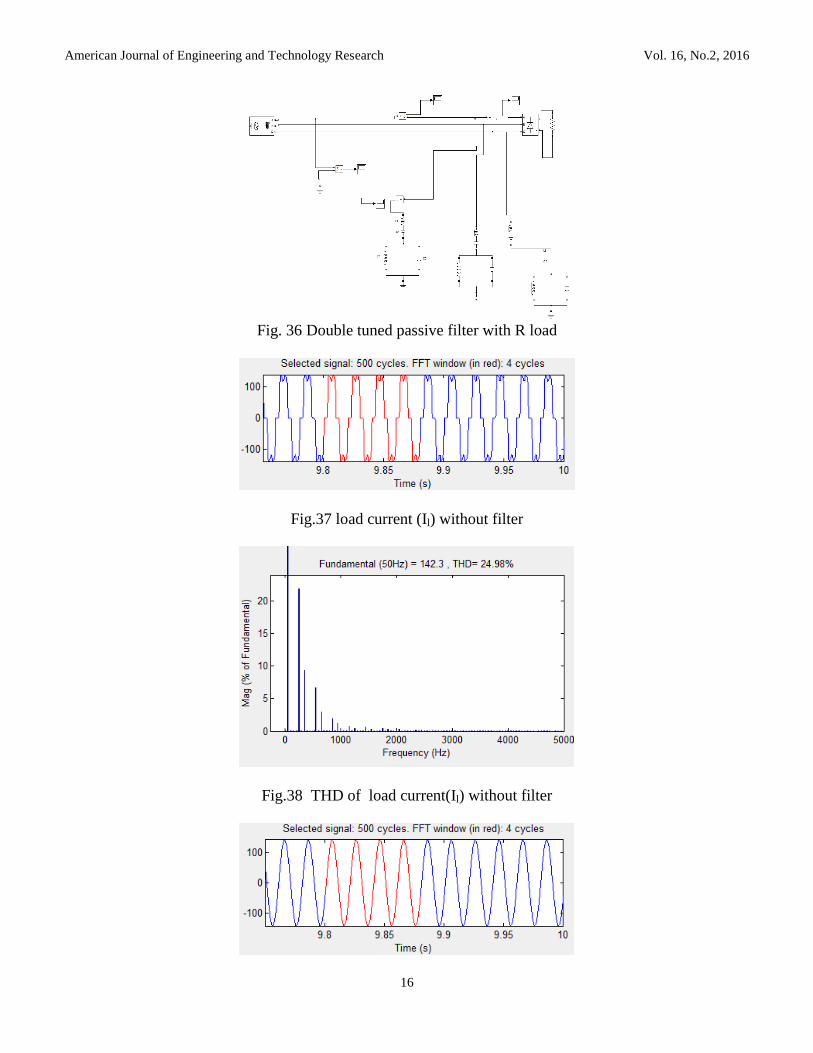
Fig. 36 Double tuned passive filter with R load
Fig.37 load current (Il) without filter
Fig.38 THD of load current(Il) without filter

American Journal of Engineering and Technology Research Vol. 16, No.2, 2016
17
Fig.39 load current (Il) with filter
Fig.40 THD of load current (Il) with filter
Fig.41 5th
& 7th
harmonic currents
Table 3. Harmonics without filter
Type of System
Harmonics
without
filter
3r
d
5th
7th
Three phase system
connected to bridge rectifier
with R-L load
0 21.
6
9.
65
Three phase system
connected to bridge rectifier
with R-L-E load
0.
1
28.
6
6.
34
Three phase system 0 21. 9.
American Journal of Engineering and Technology Research Vol. 16, No.2, 2016
18
Type of System
Harmonics
without
filter
3r
d
5th
7th
connected to bridge rectifier
with R load
6 65
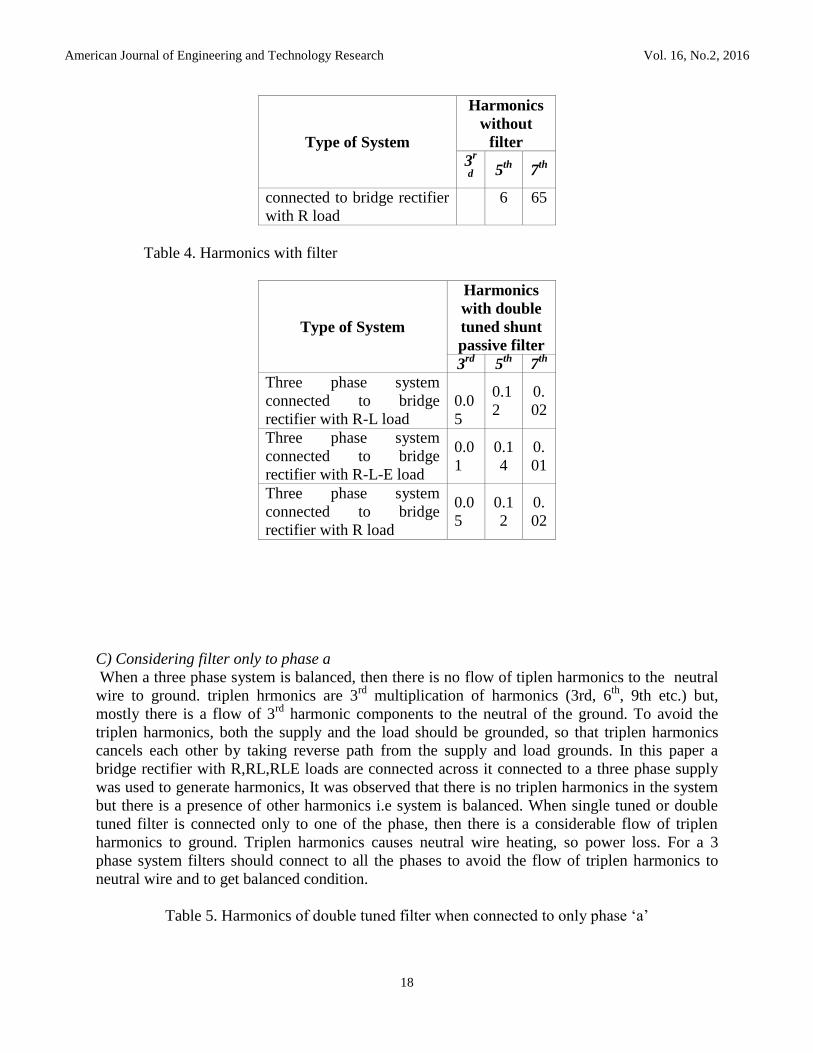
Table 4. Harmonics with filter
Type of System
Harmonics
with double
tuned shunt
passive filter
3rd
5th
7th
Three phase system
connected to bridge
rectifier with R-L load
0.0
5
0.1
2
0.
02
Three phase system
connected to bridge
rectifier with R-L-E load
0.0
1
0.1
4
0.
01
Three phase system
connected to bridge
rectifier with R load
0.0
5
0.1
2
0.
02
C) Considering filter only to phase a
When a three phase system is balanced, then there is no flow of tiplen harmonics to the neutral
wire to ground. triplen hrmonics are 3rd
multiplication of harmonics (3rd, 6th
, 9th etc.) but,
mostly there is a flow of 3rd
harmonic components to the neutral of the ground. To avoid the
triplen harmonics, both the supply and the load should be grounded, so that triplen harmonics
cancels each other by taking reverse path from the supply and load grounds. In this paper a
bridge rectifier with R,RL,RLE loads are connected across it connected to a three phase supply
was used to generate harmonics, It was observed that there is no triplen harmonics in the system
but there is a presence of other harmonics i.e system is balanced. When single tuned or double
tuned filter is connected only to one of the phase, then there is a considerable flow of triplen
harmonics to ground. Triplen harmonics causes neutral wire heating, so power loss. For a 3
phase system filters should connect to all the phases to avoid the flow of triplen harmonics to
neutral wire and to get balanced condition.
Table 5. Harmonics of double tuned filter when connected to only phase ‘a’

American Journal of Engineering and Technology Research Vol. 16, No.2, 2016
19
Type of System
Harmonics
with double
tuned shunt
passive filter
3rd
5th
7th
Three phase system
connected to bridge
rectifier with R-L load
3.45 0.1
1
0.
02
Three phase system
connected to bridge
rectifier with R-L-E load
10.0
2
0.1
3
0.
01
Three phase system
connected to bridge
rectifier with R load
3.47 0.1
1
0.
02
Table 6. Harmonics of single tuned filter when connected to only phase ‘a’
Type of System
Harmonics
with single
tuned shunt
passive filter
3rd
5th
7th
Three phase system
connected to bridge
rectifier with R-L load
3.47 0.6
7
0.
04
Three phase system
connected to bridge
rectifier with R-L-E load
10.0
7
0.7
8
0.
02
Three phase system
connected to bridge
rectifier with R load
3.49 0.6
7
0.
04
V CONCLUSION
From the analysis, the double tuned filter gives better performance than single tuned filter. The
size of a double tuned filter is less; harmonic elimination is more as compared to single tuned
filter. It was observed that there is a flow of triplen harmonics through the ground when filter is
connected to only one phase out of three phases i.e. system becomes unbalanced.
Parameters Value
3 Phase voltage(Vs),
Source
inductance(Ls),
L5,C5, L7, C7 for
single tuned.
2000V,15mH,13.5m
H,30µF,6.89mH,30
µF

American Journal of Engineering and Technology Research Vol. 16, No.2, 2016
20
Parameters Value
3 Phase voltage(Vs),
Source
inductance(Ls),
L1,C1, L2, C2 for
double tuned.
2000V,15mH,4.56
mH,60µF,5.56e-
4mH,5.5e
-4F
REFERENCES
[1] George. J. Wakileh, “Power System Harmonics,” Germany, Springer-Verlag, 2001. [2] Arillaga.J. J, Bradley. D. A., Bodger. P.S., “Power System Harmonics,” John Wiley and
Sons, New York, 1985. [3] HE Yi-hong, SU Heng “ A New Method of Designing Double –tuned Filter” Proceedings of
the 2nd
international conference on computer science and electronics engineering(ICCSEE 2013).
[4] Wang Zhaoan, Yang Jun, etc. Harmonic Suppression and Reactive Power Compensation[M]. Beijing: CHINA MACHINE PRESS, 2010.
[5] XIAO Yao, SHANG Chun, etc. Multi-tuned Passive Filters with Less Power Loss[J]. Automation of Electric Power Systems, 2006, 19(30): 69-72.
[6] Kang Ming-cai, Zhou Jia-hua. Compensates the double tuned filter element parameter change based on controllable reactor[C]// Electricity Distribution, 2008. CICED 2008, 2008.
[7] Yu Ming tao, Chen Jianye, Wang Weian, Wang Zanji. A double tuned filter based on controllable reactor[C]// Power Electronics, Electrical Drives, Automation and Motion, 2006. SPEEDAM, 2006: 1232-1235.
[8] Xiao Yao. Algorithm for the Parameters of Double tuned Filter[J]. USA: IEEE, 1998, 1: 154-157.
[9] LI Pu-ming, XU Zheng, etc.Algorithm for the Parameters of AC Filters in HVDC Transmission System[J]. Proc. CESS, 2008, 16(28):115-120.
[10] Kang Ming-cai, Zhiqian Bo, Xiping Zhao. The Parameters Calculation and Simulation Research about Two Types Structure of Double-tuned Filter[C]// Universities Power Engineering Conference(UPEC), 2010 45
th International. 2010: 1-4.