perforated steel square tube sign … steel 1/2" hex head traffic @ 18" long steel angle 1...
TRANSCRIPT

Anchor
Ground/Concrete
PERFORATED STEEL SQUARE
12
"
18
"
1"
4"5
"6"
x 10 Ga.
2 3/16" x 2 3/16"
ny-lock nut
stainless steel
1/2" Hex head
TRAFFIC
@ 18" long steel angle
1 1/2" x 1 1/2" x 12 Ga.
TUBE SIGN BREAKAWAY SYS
1 14
steel plate
5/8" Triangular
steel ball bearing
(6) 17/32" Stainless
welded to steel plate
bottom steel tubing
2" x 2" x 1/4" @ 6" Long
bolt w/ washer and nut
connector stainless steel
(3) 1/2" x 3" Hex head
ball bearing housing
1/2" Thick polypropylene
grade 5 steel bolt
3/8" x 3" Long hex head
four sides
7/16" Hole
steel plate
5/8" Triangular
grade 5 steel nut
3/8" Hex head
steel flat washer
1/2" Stainless
two sides only
7/16" Hole
15.5"
1’
Weld
1/8"
Weld
1/8"
Weld
1/8"
steel tubing
1 1/2" x 1 1/2" x 12 Ga.
BREAKAWAY ASSEMBLY, M-02
TOP VIEW
(PRE-ASSEMBLED)
PURPOSES ONLY
TO BE USED FOR MAINTENANCE
DHD
AJU
(SPECIAL DETAIL) 03/20/12SIGN-205-A
(SPECIAL DETAIL)
DEPARTMENT DIRECTOR MICHIGAN DEPARTMENT OF TRANSPORTATION
OF
SHEET
PLAN DATEF.H.W.A. APPROVALCHECKED BY:
DRAWN BY:
Michigan Department of Transportation
BUREAU OF HIGHWAY DEVELOPMENT STANDARD PLAN FOR
APPROVED BY:
APPROVED BY:
Kirk T. Steudle
BY
PREPARED
DESIGN DIVISION
DIRECTOR, BUREAU OF FIELD SERVICES
DIRECTOR, BUREAU OF HIGHWAY DEVELOPMENT

Winged anchor assembly 2 1/4" x 36" - 2 1/2" x 18" for soil installation
Assembly, square post breakaway 2 3/16" 10 ga.
Post, inner 2 3/16" x 7’ 10 ga.
Post, outer 2 1/2" x 14’ 10 ga.
3/8"- 16 x 3", grade 5 hex head steel bolts with nuts (5 each)
Assembly, ball bearing plate
1/2"- 13 x 3" stainless steel hex head bolts with nuts & washers
3/8" aluminum drive rivet (use with type iii signs only)
Assembly, square post breakaway 2 1/4" x 36", 12 ga. for concrete installation
M-01
M-02
M-03
M-04
M-05
M-07
M-08
M-11
M-12
M-13
NOTES:
5/16"- 18 grade 5 large corner bolt with nut
2 14
LIST OF MATERIALS
NUMBER
MDOT PART
TO BE USED FOR MAINTENANCE PURPOSES ONLY
SIGN-205-A(SPECIAL DETAIL)
according to the number of posts required for proper sign placement.
Quantity of materials used for the single post installation will be increased 4.
(sheet 9 of 11).
M-12 rivets are used for Type III signs only. refer to installation instructions 3.
The anchor M-01 is used for soil and the m-13 is for concrete installation.2.
Refer to the wind-load charts (sheet 11 of 14) for appropriate sign post installation.1.
03/20/12
NOT TO SCALE
NOTE: THE ORIGINAL SIGNED COPY IS KEPT ON FILE AT THE MICHIGAN DEPARTMENT OF TRANSPORTATION.
MICHIGAN DEPARTMENT OF TRANSPORTATION
BUREAU OF HIGHWAY DEVELOPMENT STANDARD PLANPLAN DATEF.H.W.A. APPROVAL
SHEET
OF
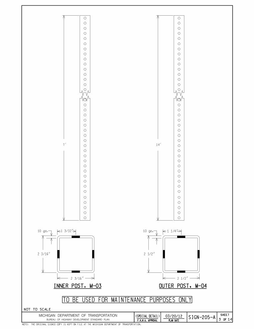
7’
10 ga.
2 3/16"
2 3/16"
1 3/32" 10 ga. 1 1/4"
2 1/2"
2 1/2"
14’
3 14
INNER POST, M-03 OUTER POST, M-04
TO BE USED FOR MAINTENANCE PURPOSES ONLY
SIGN-205-A(SPECIAL DETAIL) 03/20/12
NOT TO SCALE
NOTE: THE ORIGINAL SIGNED COPY IS KEPT ON FILE AT THE MICHIGAN DEPARTMENT OF TRANSPORTATION.
MICHIGAN DEPARTMENT OF TRANSPORTATION
BUREAU OF HIGHWAY DEVELOPMENT STANDARD PLANPLAN DATEF.H.W.A. APPROVAL
SHEET
OF
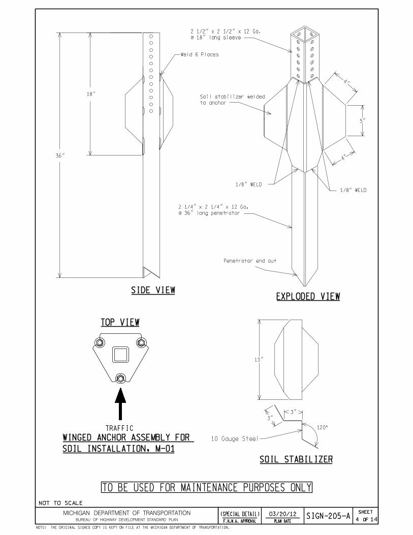
SIDE VIEWEXPLODED VIEW
36"
18"
TRAFFIC
SOIL INSTALLATION, M-01
WINGED ANCHOR ASSEMBLY FOR
Penetrator end cut
to anchor
Soil stabilizer welded
@ 18" long sleeve
2 1/2" x 2 1/2" x 12 Ga.
@ 36" long penetrator
2 1/4" x 2 1/4" x 12 Ga.
4 14
4"
5"
4"
SOIL STABILIZER
10 Gauge Steel
120°
3"
3"
13"
1/8" WELD
1/8" WELD
TOP VIEW
TO BE USED FOR MAINTENANCE PURPOSES ONLY
SIGN-205-A(SPECIAL DETAIL)
Weld 6 Places
03/20/12
NOT TO SCALE
NOTE: THE ORIGINAL SIGNED COPY IS KEPT ON FILE AT THE MICHIGAN DEPARTMENT OF TRANSPORTATION.
MICHIGAN DEPARTMENT OF TRANSPORTATION
BUREAU OF HIGHWAY DEVELOPMENT STANDARD PLANPLAN DATEF.H.W.A. APPROVAL
SHEET
OF

SIDE VIEWEXPLODED VIEW
3/8" Aluminum drive rivet1 1/2"
2"
1"
3/16"
3/8"
3/4"
36"
18"
see (sheet 9 of 11)
all around
1/8" Fillet weld
M-11
M-12
M-05
Penetrator end cut
@ 18" long sleeve
2 1/2" x 2 1/2" x 12 Ga.
@ 36" long penetrator
2 1/4" x 2 1/4" x 12 Ga.
(1) 5/16" - 18 Hex steel nut
(5) 3/8" - 16 Hex steel nut
5 14
head steel bolt
(5) 3/8" - 16 x 3" Grade 5 hex
corner steel bolt
(1) 5/16" - 18 Grade 5 large
TO BE USED FOR MAINTENANCE PURPOSES ONLY
SIGN-205-A(SPECIAL DETAIL) 03/20/12
NOT TO SCALE
NOTE: THE ORIGINAL SIGNED COPY IS KEPT ON FILE AT THE MICHIGAN DEPARTMENT OF TRANSPORTATION.
MICHIGAN DEPARTMENT OF TRANSPORTATION
BUREAU OF HIGHWAY DEVELOPMENT STANDARD PLANPLAN DATEF.H.W.A. APPROVAL
SHEET
OF
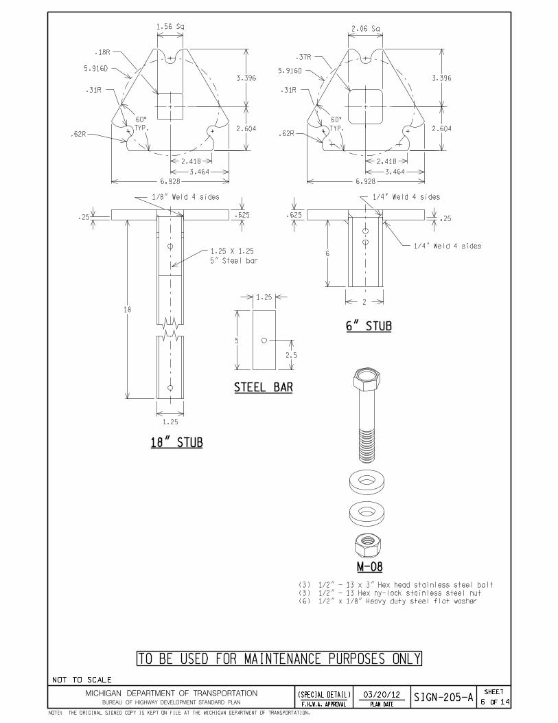
(6) 1/2" x 1/8" Heavy duty steel flat washer
M-08
(3) 1/2" - 13 x 3" Hex head stainless steel bolt
(3) 1/2" - 13 Hex ny-lock stainless steel nut
6 14
.625.625
.62RTYP.
.62R
.31R
.18R
TYP.
.37R
1/4" Weld 4 sides1/8" Weld 4 sides
1.25
2
18
6
.31R
6" STUB
18" STUB
.25 .25
2.06 Sq1.56 Sq
2.418
3.464
6.928
2.418
3.464
6.928
2.604
5.916D
3.396
2.604
3.396
5.916D
1.25 X 1.25
5" Steel bar
5
1.25
STEEL BAR
2.5
1/4" Weld 4 sides
TO BE USED FOR MAINTENANCE PURPOSES ONLY
SIGN-205-A03/20/12(SPECIAL DETAIL)
NOT TO SCALE
NOTE: THE ORIGINAL SIGNED COPY IS KEPT ON FILE AT THE MICHIGAN DEPARTMENT OF TRANSPORTATION.
MICHIGAN DEPARTMENT OF TRANSPORTATION
BUREAU OF HIGHWAY DEVELOPMENT STANDARD PLANPLAN DATEF.H.W.A. APPROVAL
SHEET
OF
7 14
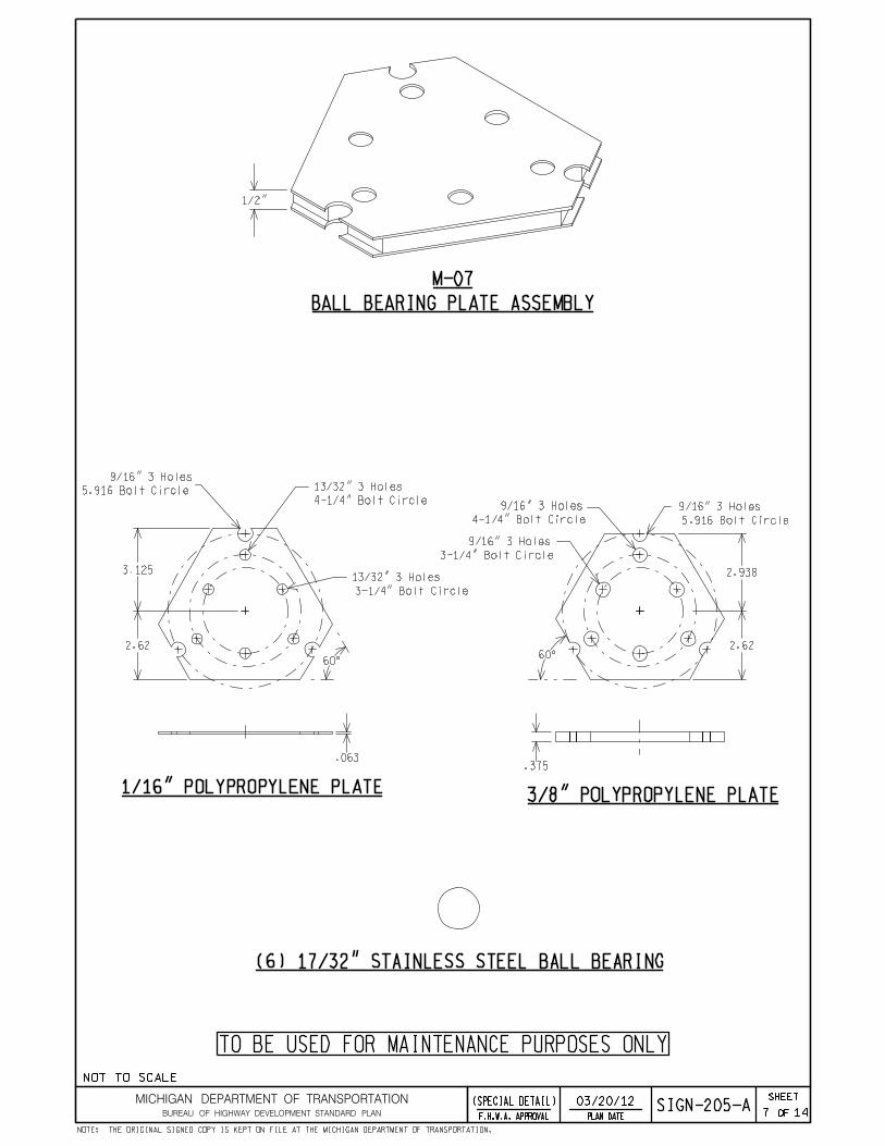
1/2"
.063.375
2.62
2.938
4-1/4" Bolt Circle
9/16" 3 Holes
3-1/4" Bolt Circle
9/16" 3 Holes
2.62
3.125
4-1/4" Bolt Circle
13/32" 3 Holes
3-1/4" Bolt Circle
13/32" 3 Holes
60°60°
1/16" POLYPROPYLENE PLATE3/8" POLYPROPYLENE PLATE
5.916 Bolt Circle
9/16" 3 Holes
5.916 Bolt Circle
9/16" 3 Holes
(6) 17/32" STAINLESS STEEL BALL BEARING
BALL BEARING PLATE ASSEMBLY
M-07
TO BE USED FOR MAINTENANCE PURPOSES ONLY
SIGN-205-A03/20/12(SPECIAL DETAIL)
NOT TO SCALE
NOTE: THE ORIGINAL SIGNED COPY IS KEPT ON FILE AT THE MICHIGAN DEPARTMENT OF TRANSPORTATION.
MICHIGAN DEPARTMENT OF TRANSPORTATION
BUREAU OF HIGHWAY DEVELOPMENT STANDARD PLANPLAN DATEF.H.W.A. APPROVAL
SHEET
OF

C
F
A
B
H
A
M-05
M-05AM-05
M-08
M-08B
M-07
M-08B
M-08A
M-05AM-05
M-05A
INSTALLATION CHECKLIST
3/8" x 3" bolts (M-05) and nuts (M-05a).
18" stub (f) of breakaway assembly and fasten with three
the allowable sign area per post/windload charts), on the
14. Slide appropriate upright post assembly (h), (refer to
to 40 ft-lbs maximum.
stainless steel ny-lock nuts (M-08a) in a circular pattern
13. After fastening all hardware, torque the three 1/2"
holes of the triangular points.
12. Repeat step 9, 10 & 11 on the two remaining notched
snugly down against the top flat washer (M-08b).
(m-08a) to the stainless steel bolt (M-08) and tighten
11. Complete by fastening the stainless steel ny-lock nut
above bolts (M-08).
10. Place the second flat washer (M-08b) down on to the
through notched hole of assembly (c), (M-07) and (f).
9. Insert above bolt (M-08) with flat washer (M-08b) up
inverted 1/2" x 3" stainless steel bolts (M-08).
8. Slide each flat washer (M-08b) on each of the three
6" stub (c).
7. Align the 18" stub (f), the ball bearing (m-07) and the
with the 3 hole side of (f) facing oncoming traffic.
6. Place the 18" stub (f) on top of the ball bearing (e)
(c).
5. Place the ball bearing assembly (M-07) on the 6" stub
14.
4. If breakaway assembly is pre-assembled, proceed to step
(M-05) and nuts (M-05a).
flow(see figure 1) and fasten with two 3/8" x 3" bolts
assembly having the bolt location align with traffic
3. Slide 6" stub (c) of breakaway assembly into anchor
grade.
2. Install anchor assembly allowing only two holes above
12th hole from the top of anchor (as shown).
bolts (M-11) and two 3/8" nuts (M-11a) through the 7th and
(b) to the anchor (a) and fastened with two 3/8" corner
b) For standard soil installation, attach soil stabilizer
concrete footings.
32" deep and 8" minimum diameter hole is required for
a) For concrete installation (required in weak soil), a
ground and align with the traffic flow (see figure 1).
1. Install the appropriate anchor assembly (a) into the
TRAFFIC FLOW
8 14
1/8" Weld
FIGURE 1.
TO BE USED FOR MAINTENANCE PURPOSES ONLY
SIGN-205-A03/20/12(SPECIAL DETAIL)
1/8" Weld
NOT TO SCALE
NOTE: THE ORIGINAL SIGNED COPY IS KEPT ON FILE AT THE MICHIGAN DEPARTMENT OF TRANSPORTATION.
MICHIGAN DEPARTMENT OF TRANSPORTATION
BUREAU OF HIGHWAY DEVELOPMENT STANDARD PLANPLAN DATEF.H.W.A. APPROVAL
SHEET
OF
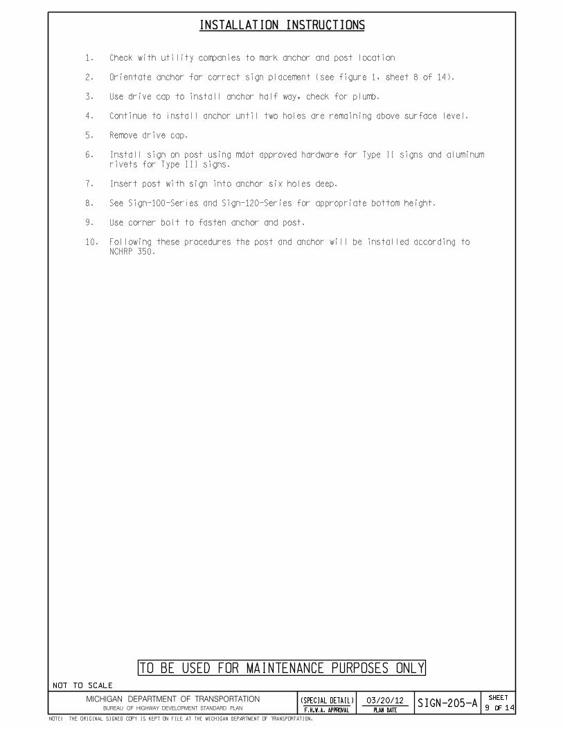
INSTALLATION INSTRUCTIONS
9 14
TO BE USED FOR MAINTENANCE PURPOSES ONLY
SIGN-205-A03/20/12(SPECIAL DETAIL)
NCHRP 350.
Following these procedures the post and anchor will be installed according to 10.
Use corner bolt to fasten anchor and post.9.
See Sign-100-Series and Sign-120-Series for appropriate bottom height.8.
Insert post with sign into anchor six holes deep.7.
rivets for Type III signs.
Install sign on post using mdot approved hardware for Type II signs and aluminum 6.
Remove drive cap.5.
Continue to install anchor until two holes are remaining above surface level.4.
Use drive cap to install anchor half way, check for plumb.3.
Orientate anchor for correct sign placement (see figure 1, sheet 8 of 14).2.
Check with utility companies to mark anchor and post location1.
NOT TO SCALE
NOTE: THE ORIGINAL SIGNED COPY IS KEPT ON FILE AT THE MICHIGAN DEPARTMENT OF TRANSPORTATION.
MICHIGAN DEPARTMENT OF TRANSPORTATION
BUREAU OF HIGHWAY DEVELOPMENT STANDARD PLANPLAN DATEF.H.W.A. APPROVAL
SHEET
OF

all around
1/4" fillet weld
350 standards for breakaway sign supports.
ground level upon impact by a vehicle. The breakaway system conforms to nchrp
The breakaway system is designed to allow a traffic sign to breakaway near
Basic Types: Triangular, three bolt base.
Basic Components:
washers.
coupling, and clamping bolts including nuts and flat
Top coupling, middle ball bearing retainer, bottom
tubing
Steel
ny-lock nut
Stainless steel
flat washer
stainless steel
Heavy duty
retainer
Ball bearing
plate
Steel
steel bolt
Stainless
tubing
Steel
10 14
PERFORATED STEEL SQUARE TUBE SIGN BREAKAWAY SYSTEM SPECIFICATIONS
14. Periodic inspection is recommended.
13. No scheduled retorque is required.
12. Clamping Bolt Torque: 40 lbs-ft maximum.
1-1/8"od.
11. Flat washers are 3/16" thick, 17/32"id,
nut.
10. Steel nuts are 1/2" stainless steel ny-lock
length.
9. Clamping Bolt Size: 1/2" diameter and 3" in
dry lubricant.
8. Clamping Bolt Type: 316 stainless steel with
and 7/32" diameter.
maximum. Ball bearings are stainless steel
7. Middle ball bearing retainer thickness: 1/2"
bolt circle diameter of 5-29/32".
6. Top and bottom triangular steel plates have a
galvanized (zinc coated) finished.
5. Both top and bottom couplings are hot-dip
psi.
50 with a minimum Yield strength of 50,000
steel plates are structural ASTM A572 Grade
4. The top and bottom 5/8" thick triangular
Yield Strength of 46,000 psi.
structural ASTM A500 Grade B with a minimum
3. The top and bottom steel tubing are
triangular steel plate.
tube (1/4" wall @ 6" long) welded to a 5/8"
2. Bottom coupling consists of a 2" square steel
long welded to a 5/8" triangular steel plate.
(2) 1-1/2" 12 ga formed steel angles @ 18"
steel tube (12 ga. wall @ 18-1/4" long) and
1. Top coupling consists of a 1-1/2" square
TO BE USED FOR MAINTENANCE PURPOSES ONLY
SIGN-205-A03/20/12(SPECIAL DETAIL)
NOT TO SCALE
NOTE: THE ORIGINAL SIGNED COPY IS KEPT ON FILE AT THE MICHIGAN DEPARTMENT OF TRANSPORTATION.
MICHIGAN DEPARTMENT OF TRANSPORTATION
BUREAU OF HIGHWAY DEVELOPMENT STANDARD PLANPLAN DATEF.H.W.A. APPROVAL
SHEET
OF

Single Double
*7’
L2/3
L
L/6L/6
**
(max.)
18.5 sq. ft.
(max.)
38.0 sq. ft
height and support spacings.
Sign-100-Series and Sign-120-Series for required minimum bottom
the travel lane pavement to the bottom of the sign panel. See
The bottom height is defined as height from the near edge of */**
11 14
NOTE:
For signs over 38 sq. ft use the charts on Sign-150-Series.
FOR 90 MPH WIND SPEED
PERFORATED STEEL SQUARE TUBE SIGN BREAKAWAY SYSTEM
TO BE USED FOR MAINTENANCE PURPOSES ONLY
SIGN-205-A03/20/12(SPECIAL DETAIL)
NOT TO SCALE
NOTE: THE ORIGINAL SIGNED COPY IS KEPT ON FILE AT THE MICHIGAN DEPARTMENT OF TRANSPORTATION.
MICHIGAN DEPARTMENT OF TRANSPORTATION
BUREAU OF HIGHWAY DEVELOPMENT STANDARD PLANPLAN DATEF.H.W.A. APPROVAL
SHEET
OF

Concrete median barrier
typ.
10
"
5"5
"
by mdot sign support typical plans)
(spacing as called for
7/16" Diameter holes (typ.)
1/4"Plate
2.5" 1.25"
7.5
"1
.2
5"
(SQUARE TUBE SUPPORT)
2.5"
5/16"
3"
1.5"
11/16" ! Holes (4)
(4" embedment)
with washers & nuts
full thread anchor bolt
5/8" x 6" Galvanized steel
FRONT ELEVATION SIDE ELEVATION
BASE PLATE DETAILS
inserted over 6" stub
Steel sign support
back to back
Type III signs
cutout for stub
Square hole
around
with 1/4" fillet weld
as weld socket joint
Connect stub to plate
CONCRETE MEDIAN BARRIER CONNECTION
(stub)
6 5/16" Steel tubing
1 3/4" x 1 3/4 " x 3/4"
unistrut tubing galvanized
2" x 2" (12 Ga) perforated
12 14
TO BE USED FOR MAINTENANCE PURPOSES ONLY
SIGN-205-A03/20/12(SPECIAL DETAIL)
NOT TO SCALE
NOTE: THE ORIGINAL SIGNED COPY IS KEPT ON FILE AT THE MICHIGAN DEPARTMENT OF TRANSPORTATION.
MICHIGAN DEPARTMENT OF TRANSPORTATION
BUREAU OF HIGHWAY DEVELOPMENT STANDARD PLANPLAN DATEF.H.W.A. APPROVAL
SHEET
OF
13 14
mdot sign support typical plans)
(spacing as called for by
7/16" Diameter holes (typ.)
Concrete glare screen
1"
1"
7"6
"1
.5
"
10
"
7"
+
(typ.)
3/4" R m
ax.
2 5/8"7/8"19"
5/16"
6"
(Typ.)
.687"
1.5
"3
"
galvanized
unistrut tubing
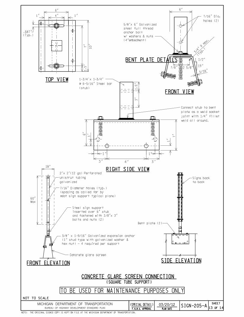
2"x 2"(12 ga) Perforated
18"
60"
Max
Bent plate (2)
bolts and nuts (2)
and fastened with 3/8"x 3"
inserted over 6" stub
Steel sign support
weld all around.
joint with 1/4" fillet
plate as a weld socket
Connect stub to bent
1"
6"
1"
3" 4" 3"
hex nut) - 4 required per support
(1" stud type with galvanized washer &
3/8" x 1-9/16" Galvanized expansion anchor
to back
Signs back
1" 4" 1"
holes (2)
7/16" Dia.
1 1/2"
(4"embedment)
w/ washers & nuts
anchor bolt
steel full thread
5/8"x 6" Galvanized
FRONT ELEVATIONSIDE ELEVATION
CONCRETE GLARE SCREEN CONNECTION
RIGHT SIDE VIEW
TOP VIEW
FRONT VIEW
BENT PLATE DETAILS
(SQUARE TUBE SUPPORT)
TO BE USED FOR MAINTENANCE PURPOSES ONLY
SIGN-205-A03/20/12(SPECIAL DETAIL)
(stub)
@ 6-5/16" Steel bar
1-3/4’x 1-3/4"
NOT TO SCALE
NOTE: THE ORIGINAL SIGNED COPY IS KEPT ON FILE AT THE MICHIGAN DEPARTMENT OF TRANSPORTATION.
MICHIGAN DEPARTMENT OF TRANSPORTATION
BUREAU OF HIGHWAY DEVELOPMENT STANDARD PLANPLAN DATEF.H.W.A. APPROVAL
SHEET
OF

14 14
NOTES:
TO BE USED FOR MAINTENANCE PURPOSES ONLY
SIGN-205-A03/20/12(SPECIAL DETAIL)
pipe support or a square tube is plumb on the glare screen or concrete barrier wall.
Glare screen and barrier connections must be installed to ensure that either a 8.
median barrier connection (square tube support).
Concrete median barriers having a top width of 6" or wider shall use the concrete 7.
section 919 of the current Standard Specifications for Construction.
Sign substrates shall be aluminum for ground mount and barrier connections per 6.
ft. & a back to back sign connection with a maximum of 15 sq.ft.
Square tube support suitable for single sign connection with a maximum of 7.5 sq. 5.
a back to back sign connection with a maximum of 8 sq. ft.
Pipe support suitable for a single sign connection with a maximum of 4 sq. ft. & 4.
The adhesive anchoring system tested to ASTM E488.3.
A307.
full thread anchor bolt manufactured to ASTM A36 Mod55. Hex bolt manufactured to
All fastening hardware (bolts, nuts and washers) shall be galvanized to ASTM 153, 2.
Specifications for Construction after fabrication.
channels, square tube, stub & plate) shall be per the current MDOT Standard
The materials and galvanized finish for the connection components (steel pipe, 1.
NOT TO SCALE
NOTE: THE ORIGINAL SIGNED COPY IS KEPT ON FILE AT THE MICHIGAN DEPARTMENT OF TRANSPORTATION.
MICHIGAN DEPARTMENT OF TRANSPORTATION
BUREAU OF HIGHWAY DEVELOPMENT STANDARD PLANPLAN DATEF.H.W.A. APPROVAL
SHEET
OF