perfluorocarbon-filled poly(lactide-co-gylcolide) nano- and microcapsules as artificial oxygen...
TRANSCRIPT

Journal of Microencapsulation, 2010; 27(2): 122–132
RESEARCH ARTICLE
Perfluorocarbon-filled poly(lactide-co-gylcolide)nano- and microcapsules as artificial oxygen carriersfor blood substitutes: a physico-chemical assessment
J. Bauer1, M. Zahres1, A. Zellermann1, M. Kirsch2, F. Petrat2, H. de Groot2 and C. Mayer1
1University Duisburg-Essen, Institute of Physical Chemistry, RIBS and CeNIDE, Essen, Germany and2University Duisburg-Essen, Institute of Physiological Chemistry, Essen, Germany
AbstractThe physico-chemical suitability of perfluorocarbon-filled capsules as artificial oxygen carriers forblood substitutes is assessed on the example of biodegradable poly(lactide-co-gylcolide) micro- andnanocapsules with a liquid content of perfluorodecalin. The morphology of the capsules is studied byconfocal laser scanning microscopy using Nile red as a fluorescent marker. The mechanical stability andthe wall flexibility of the capsules are examined by atomic force microscopy. The permeability of thecapsule walls in connection with the oxygen uptake is detected by nuclear magnetic resonance. It isshown that the preparation in fact leads to nanocapsules with a mechanical stability which compareswell with the one of red blood cells. The capsule walls exhibit sufficient permeability to allow for theexchange of oxygen in aqueous environment. In the fully saturated state, the amount of oxygen dissolvedwithin the encapsulated perfluorodecalin in aqueous dispersion is as large as for bulk perfluorodecalin.Simple kinetic studies are presently restricted to the time scale of minutes, but so far indicate thatthe permeability of the capsule walls could be sufficient to allow for rapid gas exchange.
Key words: Blood replacement; poly-lactide-glycolide; oxygen carrier; gas exchange; perfluorocarbon;nanocapsules
Introduction
Micro- and nanocapsules have long been discussed as pos-
sible oxygen carriers for artificial blood replacements
(Chang 1964, Yu and Chang 1994, Riess 2001, Chang
2003, Chang 2004, Winslow 2006). Over the years, more
and more complex reproductions of red blood cells have
been developed which contain haemoglobin together with
active enzymes. All these capsule-based systems rely on
the reversible coordinative binding of oxygen to the
active centre of haemoglobin. Alternatively, a completely
different approach has been proposed which is based on a
purely physical solution of oxygen and carbon dioxide in
perfluorocarbons (Clark and Gollan 1966, Sloviter and
Kamimoto 1967, Riess 2001, Lowe 2003). In this case, the
carrier function for oxygen and carbon dioxide relies on a
physical transport phenomenon induced by local concen-
tration gradients of both gases. For use as blood
substitutes, aqueous emulsions of these compounds are
being formed in the presence of phospholipids.
They appear to be promising alternatives to the much
more complex varieties of artificial red blood cells based
on encapsulated haemoglobin. The key to their function is
the outstanding physical property of the perfluorohydro-
carbons: the high solubility of oxygen and carbon dioxide
in PFC leading to an oxygen uptake which even exceeds
the one of natural blood. This is accompanied by a low
toxicity, good handling and sterilization properties (Lowe
2003). PFC are primarily excreted as a vapour by exhalation
and therefore do not need to be degraded via a physiolog-
ical pathway. Presently, one of the main disadvantages of
PFC dispersions being used as blood substitutes lies in the
difficulty to produce a stable emulsion with a small droplet
diameter and, at the same time, to guarantee an acceptable
excretion time. Generally, it is found that those PFC which
exhibit rapid excretion yield instable emulsions, whereas
Address for correspondence: C. Mayer, Universitat Duisburg-Essen, D-45141 Essen, Germany. Tel: 0049 201 183 2570. Fax: 0049 201 183 2567.E-mail: [email protected]
(Received 15 Jan 2009; accepted 27 Apr 2009)
ISSN 0265-2048 print/ISSN 1464-5246 online � 2010 Informa UK LtdDOI: 10.3109/02652040903052002 http://www.informahealthcare.com/mnc
(Received 15 Jan 2009; accepted 27 Apr 2009)
ISSN 0265-2048 print/ISSN 1464-5246 online � 2010 Informa UK LtdDOI: 10.3109/02652040903052002 http://www.informahealthcare.com/mnc
Jour
nal o
f M
icro
enca
psul
atio
n D
ownl
oade
d fr
om in
form
ahea
lthca
re.c
om b
y G
azi U
niv.
on
08/1
7/14
For
pers
onal
use
onl
y.

those which could be prepared in stable emulsions in turn
show unacceptably long excretion times (Riess 1984, Riess
2001).
Perfluorocarbon-filled nanocapsules are already
known for their potential as contrast agents in NMR and
ultrasonic imaging (Pisani et al. 2006). In addition, they are
being discussed as controlled release systems where ultra-
sonic energy could be used for controlled particle degra-
dation (Kost et al. 1989, Pisani et al. 2006). However, they
may also represent a valuable alternative to PFC emul-
sions in an application as a blood substitute since they
possibly offer a solution for the dilemma of the dispersion
stability: as the PFC droplets are permanently encapsu-
lated, any droplet growth by fusion or by Ostwald ripening
is excluded. Therefore, the stability problem is reduced to
the challenge of avoiding agglomeration of particles, a
problem which can be solved with adequate surfactants.
A suitable encapsulation procedure for PFC has been
proposed by Pisani et al. (2006) It is based on an emulsion-
evaporation process using methylene chloride as a solvent
and poly(lactide-co-glycolide) (PLG) as the polymer form-
ing the capsule walls and generally follows the idea intro-
duced by Loxley and Vincent (1998). Conventional stirring
during the initial emulsion step leads to microcapsules
(1mm5 d5 5mm) with wall thicknesses between
0.5–2 mm. Their smaller counterparts, nanocapsules with
diameters between 70–200 nm, are accessible if the initial
dispersion is prepared by sonication.
This study is meant to approach the question if
the resulting particle dispersion, regarding its physico-
chemical properties, is able to act as a possible blood sub-
stitute. In this sense, three critical points have to be taken
into account: (i) Do the resulting particles in fact show the
morphology of capsules with a diameter small enough to
allow for circulation? (ii) Do the PLG capsules exhibit
enough mechanical stability to remain intact for longer
periods of circulation in the blood stream? (iii) Does the
capsule wall from PLG allow for sufficient oxygen
exchange between the liquid PFC and the external
medium? These issues in mind, a physico-chemical
assessment of PLG capsules is performed using confocal
laser scanning microscopy, atomic force microscopy
(AFM), nuclear magnetic resonance (NMR) and video
microscopy to characterize the system. All results are eval-
uated based on the requirements connected to a possible
application as an artificial oxygen carrier.
Materials and methods
Chemicals
Perfluordecaline (PFD) is purchased from F2 Chemicals
Ltd. (Lea Lane, Preston, UK). Poly(DL-lactide-co-glycolide)
(50 : 50) produced by LACTEL (B6013-2) is obtained from
NRC Nordmann Rassmann GmbH (Hamburg, Germany).
The fluorescence marker Nile red is delivered by Sigma
(Taufkirchen, Germany).
Capsule preparation
The preparation of the PLG nanocapsules basically follows
the procedure described by Pisani et al. (2006) for capsules
of decreased size. An organic solution of PLG and PFC in
methylene chloride is emulsified in an aqueous solution of
1.5% sodium cholate under intensive stirring.
Subsequently, the emulsion is sonicated in an ice bath
for 30 s. The methylene chloride is then evaporated
under magnetic stirring for 3 h at 20�C. The remaining
dispersion of PLG nanocapsules is used without further
processing. In order to study the effect of larger capsule
size, a sample of dispersed PLG microcapsules is produced
by repeating the described procedure with the exception
of the sonication step. In the following, it will be differen-
tiated between nanocapsules and microcapsules,
accordingly.
Laser scanning microscopy (LSM)
A laser scanning microscope (LSM 510, Zeiss,
Oberkochen, Germany) equipped with a helium/neon
laser is used to study the morphology of the microcap-
sules; imaging of nanocapsules (d5 1 mm) is not possible
due to the resolution limit of an optical system. Nile red-
stained PLG microcapsules are diluted 50–200-fold with
0.9% NaCl solution and placed on an object slide or
within a modified Pentz chamber. The objective lens is a
63� NA 1.40 plan-apochromat. Red fluorescence of Nile
red excited at 543 nm is collected through a 585 nm long-
pass filter. The pinhole is set between 46–95 mm, produ-
cing confocal optical slices of 0.45–0.75mm in thickness.
Three-dimensional microfluorographs are obtained by
high resolution optical sectioning (0.45 mm, 50% overlap-
ping) of the microcapsules along their z-axis. Image pro-
cessing and evaluation are performed using the software
of the LSM 510 imaging system.
Atomic force microscopy (AFM)
All AFM measurements are performed on a ‘Nano Wizard’
from JPK Instruments (Berlin, Germany) using non-
contact/tapping mode high resonance frequency (NCH)
cantilevers from NanoWorld (Neuchatel, Switzerland).
An intermittent contact mode at a frequency of 320 kHz
is used for the AFM imaging. The scan rate is adjusted to
Perfluorocarbon-filled capsules as artificial oxygen carriers 123
Jour
nal o
f M
icro
enca
psul
atio
n D
ownl
oade
d fr
om in
form
ahea
lthca
re.c
om b
y G
azi U
niv.
on
08/1
7/14
For
pers
onal
use
onl
y.

1 Hz for capsules with d5 250 nm and to 0.5 Hz for cap-
sules with 250 nm5 d5 750 nm. In order to obtain data
on the mechanical performance of the capsules, plots of
force vs tip position are recorded during the indentation of
individual capsules. Preparing these tests, the tip is hori-
zontally positioned over the centre of the capsule and
brought in contact with the capsule membrane. During
the actual testing procedure, the cantilever holder is
moved vertically over a distance of typically 200 nm
towards the carrier surface within a period of 5 s. The can-
tilever deformation, constantly monitored during this pro-
cess, is used to calculate the actual tip position as well as
the force which is applied to the capsule membrane.
Nuclear magnetic resonance (NMR)
The NMR experiments are run on a Bruker DRX 500 spec-
trometer at a fluorine resonance frequency of 500 Hz.
Simple single-pulse excitation is used to obtain fluorine
line spectra. An external standard is used for a reliable
determination of the chemical shifts. Spin-lattice relax-
ation times are determined in a conventional inversion
recovery experiment. For measurements under variation
of the atmosphere, a home-built sample holder is used
which carries individual gas inlet capillaries for oxygen
and nitrogen in order to enable an instantaneous switch-
ing between different atmospheres. The gas flow for
oxygen and nitrogen is adjusted such that the overall
flow rate amounted to 0.36 ml min�1. The gas flow rate
is a compromise between sufficient mixing of the liquid
phase (in order to minimize gas concentration gradients in
the liquid) and minimal sample inhomogeneity due to gas
bubbles which causes broadening of the NMR signals. The
exchange between oxygen and nitrogen atmosphere and
vice versa is induced by simultaneous opening and closing
of the respective valves. In the time resolved NMR mea-
surement during the gas treatment, a single pulse experi-
ment is repeated every 20 s. Each resulting free induction
decay (FID) is Fourier transformed to yield a (Altinbas
et al. 2006) F spectrum for the determination of the time
dependent chemical shift. The degree of oxygen saturation
in the fluorinated hydrocarbon is then calculated from the
chemical shift using data from independent calibration
measurements.
Video microscopy
The procedure of using video microscopy for a determi-
nation of the particle size distribution has been described
in detail elsewhere (Finder et al. 2004). Basically, optical
dark field microscopy is used for the observation of the
Brownian motion of the capsules. The motion of several
capsules is tracked simultaneously by online video analy-
sis and sets of lateral dislocations Dx and Dy are collected
for every single particle over many time intervals Dt. Based
on the given temperature and solvent viscosity, the full set
of dislocations is then used to calculate the diameters of all
observed nanocapsules, leading to a representative size
histogram of the capsule sample.
Results
Capsule morphology and size
For initial studies on the capsule morphology, the larger
versions of the PLG capsules (microcapsules) are used due
to the limited resolution of optical microscopy. PLG micro-
capsules were diluted 50–200-fold with 0.9% NaCl solution
and placed on an object slide or within a modified Pentz
chamber. Nile red fluorescence (�exc.¼ 543 nm,
�em.� 585 nm) was visualized using laser scanning micro-
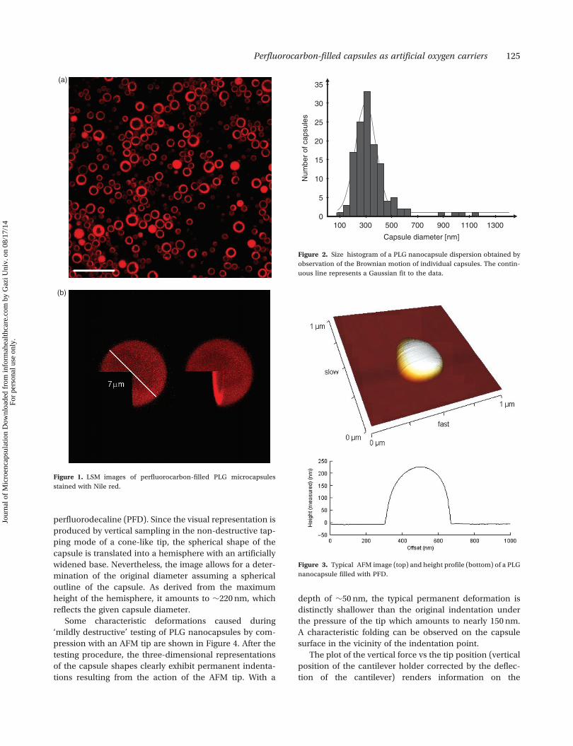
scopy. In Figure 1(a), a set of microcapsules from a repre-
sentative preparation are shown; the scale bar represents
20 mm. In Figure 1(b), the three-dimensional structure of a
typical microcapsule is visualized. The images reveal
spherical hollow structures with a diameter of 3–8 mm
(Figure 1(a)). As deduced from the circular appearance
of single confocal sections, almost all microcapsules con-
tain perfluorocarbon (perfluorodecaline, PFD), which is
not stained with Nile red. The thickness of the microcap-
sule walls varies from 0.3–2.0mm and depends strongly on
the capsule diameter; smaller microcapsules are found to
have thinner walls.
The actual nanocapsules exhibit much smaller dia-
meters as revealed by an analysis of their Brownian
motion in aqueous dispersion using video microscopy.
The resulting size histogram is shown in Figure 2. It reveals
an average capsule diameter of 300 nm with a standard
deviation of 100 nm. The size distribution is slightly asym-
metric with a distinct tailing towards larger capsule sizes.
Atomic force microscopy (AFM)
In the given context, the method of atomic force micros-
copy (AFM) is applied with two intentions: first, AFM is an
imaging technique which gives access to information on
size and shape of the capsules. Secondly, the option for
measurements of the cantilever deflection as a function of
the height allows for a mechanical characterization of the
capsule structure in non-destructive and destructive test-
ing (Fery and Weinkammer 2007). Both approaches are
used in this study.
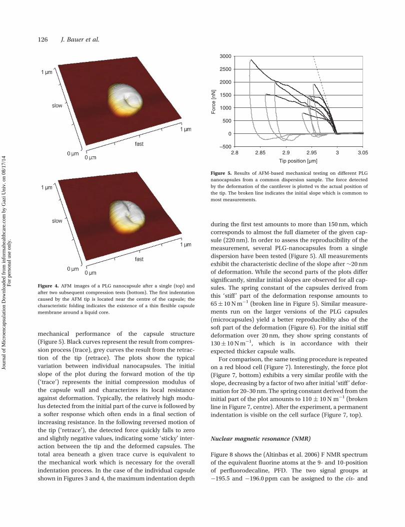
Figure 3 shows a typical AFM image and a height profile
of an original PLG nanocapsule filled with
124 J. Bauer et al.
Jour
nal o
f M
icro
enca
psul
atio
n D
ownl
oade
d fr
om in
form
ahea
lthca
re.c
om b
y G
azi U
niv.
on
08/1
7/14
For
pers
onal
use
onl
y.
perfluorodecaline (PFD). Since the visual representation is
produced by vertical sampling in the non-destructive tap-
ping mode of a cone-like tip, the spherical shape of the
capsule is translated into a hemisphere with an artificially
widened base. Nevertheless, the image allows for a deter-
mination of the original diameter assuming a spherical
outline of the capsule. As derived from the maximum
height of the hemisphere, it amounts to �220 nm, which
reflects the given capsule diameter.
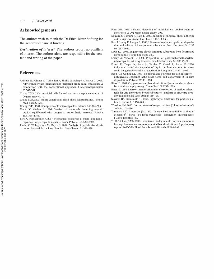
Some characteristic deformations caused during
‘mildly destructive’ testing of PLG nanocapsules by com-
pression with an AFM tip are shown in Figure 4. After the
testing procedure, the three-dimensional representations
of the capsule shapes clearly exhibit permanent indenta-
tions resulting from the action of the AFM tip. With a
depth of �50 nm, the typical permanent deformation is
distinctly shallower than the original indentation under
the pressure of the tip which amounts to nearly 150 nm.
A characteristic folding can be observed on the capsule
surface in the vicinity of the indentation point.
The plot of the vertical force vs the tip position (vertical
position of the cantilever holder corrected by the deflec-
tion of the cantilever) renders information on the
(a)
(b)
Figure 1. LSM images of perfluorocarbon-filled PLG microcapsules
stained with Nile red.
Figure 3. Typical AFM image (top) and height profile (bottom) of a PLG
nanocapsule filled with PFD.
100 300 500 700 900 1100 1300
Capsule diameter [nm]
35
30
25
20
15
10
5
0
Num
ber
of c
apsu
les
Figure 2. Size histogram of a PLG nanocapsule dispersion obtained by
observation of the Brownian motion of individual capsules. The contin-
uous line represents a Gaussian fit to the data.
Perfluorocarbon-filled capsules as artificial oxygen carriers 125
Jour
nal o
f M
icro
enca
psul
atio
n D
ownl
oade
d fr
om in
form
ahea
lthca
re.c
om b
y G
azi U
niv.
on
08/1
7/14
For
pers
onal
use
onl
y.
mechanical performance of the capsule structure
(Figure 5). Black curves represent the result from compres-
sion process (trace), grey curves the result from the retrac-
tion of the tip (retrace). The plots show the typical
variation between individual nanocapsules. The initial
slope of the plot during the forward motion of the tip
(‘trace’) represents the initial compression modulus of
the capsule wall and characterizes its local resistance
against deformation. Typically, the relatively high modu-
lus detected from the initial part of the curve is followed by
a softer response which often ends in a final section of
increasing resistance. In the following reversed motion of
the tip (‘retrace’), the detected force quickly falls to zero
and slightly negative values, indicating some ‘sticky’ inter-
action between the tip and the deformed capsules. The
total area beneath a given trace curve is equivalent to
the mechanical work which is necessary for the overall
indentation process. In the case of the individual capsule
shown in Figures 3 and 4, the maximum indentation depth
during the first test amounts to more than 150 nm, which
corresponds to almost the full diameter of the given cap-
sule (220 nm). In order to assess the reproducibility of the
measurement, several PLG-nanocapsules from a single
dispersion have been tested (Figure 5). All measurements
exhibit the characteristic decline of the slope after �20 nm
of deformation. While the second parts of the plots differ
significantly, similar initial slopes are observed for all cap-
sules. The spring constant of the capsules derived from
this ‘stiff ’ part of the deformation response amounts to
65� 10 N m�1 (broken line in Figure 5). Similar measure-
ments run on the larger versions of the PLG capsules
(microcapsules) yield a better reproducibility also of the
soft part of the deformation (Figure 6). For the initial stiff
deformation over 20 nm, they show spring constants of
130� 10 N m�1, which is in accordance with their
expected thicker capsule walls.
For comparison, the same testing procedure is repeated
on a red blood cell (Figure 7). Interestingly, the force plot
(Figure 7, bottom) exhibits a very similar profile with the
slope, decreasing by a factor of two after initial ‘stiff ’ defor-
mation for 20–30 nm. The spring constant derived from the
initial part of the plot amounts to 110 � 10 N m�1 (broken
line in Figure 7, centre). After the experiment, a permanent
indentation is visible on the cell surface (Figure 7, top).
Nuclear magnetic resonance (NMR)
Figure 8 shows the (Altinbas et al. 2006) F NMR spectrum
of the equivalent fluorine atoms at the 9- and 10-position
of perfluorodecaline, PFD. The two signal groups at
�195.5 and �196.0 ppm can be assigned to the cis- and
Figure 4. AFM images of a PLG nanocapsule after a single (top) and
after two subsequent compression tests (bottom). The first indentation
caused by the AFM tip is located near the centre of the capsule; the
characteristic folding indicates the existence of a thin flexible capsule
membrane around a liquid core.
–500
0
500
1000
1500
2000
2500
3000
2.8
Tip position [µm]
For
ce [n
N]
2.85 2.9 2.95 3 3.05
Figure 5. Results of AFM-based mechanical testing on different PLG
nanocapsules from a common dispersion sample. The force detected
by the deformation of the cantilever is plotted vs the actual position of
the tip. The broken line indicates the initial slope which is common to
most measurements.
126 J. Bauer et al.
Jour
nal o
f M
icro
enca
psul
atio
n D
ownl
oade
d fr
om in
form
ahea
lthca
re.c
om b
y G
azi U
niv.
on
08/1
7/14
For
pers
onal
use
onl
y.

–1000
0
1000
2000
3000
4000
5000
6000
7000
8000
9000
3.4
Tip position [µm]
For
ce [n
N]
3.45 3.5 3.55 3.6 3.65 3.7 3.75 3.8
Figure 7. AFM image (top) and indentation plot (bottom) obtained from a human red blood cell. The second AFM image, taken of the same red blood
cell after the testing cycle, shows a permanent indentation (arrow).
–2000
–1000
0
1000
2000
3000
4000
5000
6000
7000
8000
2.8
Tip position [µm]
For
ce [n
N]
2.85 2.9 2.95 3 3.05 3.1
Figure 6. Results of mechanical testing on different PLG capsules of several micrometers in diameter (microcapsules) from a common dispersion
sample. The plots show the typical variation between individual nanocapsules. The broken line indicates the initial slope which is common to most
measurements.
Perfluorocarbon-filled capsules as artificial oxygen carriers 127
Jour
nal o
f M
icro
enca
psul
atio
n D
ownl
oade
d fr
om in
form
ahea
lthca
re.c
om b
y G
azi U
niv.
on
08/1
7/14
For
pers
onal
use
onl
y.

the trans-isomer of PFD, respectively (Fung 1983). The
different widths of the individual (Altinbas et al. 2006)
F signals are caused by significantly different conforma-
tional dynamics of both isomers. While the cis-isomer is in
a rapid conformational equilibrium, the trans-isomer is
relatively rigid even at room temperature (Fung 1983).
The experimental key to the detection of oxygen by
NMR consists of the dipolar interaction between the para-
magnetic oxygen molecule and the fluorine nuclei. For the
(Altinbas et al. 2006) F spins observed by NMR spectro-
scopy, the interaction with oxygen directly affects two
easily detectable parameters: the chemical shifts of the
(Altinbas et al. 2006) F-signals and the spin-lattice relax-
ation time of the (Altinbas et al. 2006) F magnetization. In
case of PFD, both effects are directly correlated with the
amount of oxygen which is dissolved or, in the case of
a stable distribution equilibrium with an adjacent gas
phase, with the partial pressure of the oxygen p(O2).
Figures 9 and 10 show the dependence of the chemical
shift and of the spin lattice relaxation time of a character-
istic PFD-(Altinbas et al. 2006) F signal (the central signal
of the multiplet at �195.5 ppm) on the partial pressure of
oxygen in the external gas phase (oxygen/nitrogen with a
total pressure of 1 bar). In good approximation, both para-
meters depend linearly on p(O2). This also holds for PFD
in the encapsulated state: Figure 10 also shows the corre-
sponding plot for PFD in dispersed PLG nanocapsules (full
symbols) in direct comparison with the data for bulk PFD.
Except for a slight shift, the data points for PFD in the
nanocapsule dispersion compare well with those of the
homogeneous PFD phase.
–195.2 –195.4 –195.6 –195.8 –196.0ppm
Figure 8. 19F NMR resonance lines of the equivalent fluorine atoms at the 9- and 10-position of perfluorodecaline, PFD.
Rel
ativ
e ch
emic
al s
hift
(Hz)
Partial pressure of O2 (hPa)
200 400 600 800 1000
4080
120
160
Figure 9. Dependence of the 19F signal position (central signal of the
multiplet at�195.5 ppm, see Figure 8) on the partial pressure of oxygen
in PFD. The chemical shift is given relative to the signal position at
p(O2)¼ 0 in Hz.
Partial pressure of O2 (hPa)
200
Spi
n la
ttice
rel
axat
ion
rate
(s–1
)
0.5
400 600 800 1000
1.0
1.5
2.0
Figure 10. Dependence of the 19F spin-lattice relaxation rate of bulk
(open symbols) and nano-encapsulated PFD (full symbols) on the partial
pressure of oxygen.
128 J. Bauer et al.
Jour
nal o
f M
icro
enca
psul
atio
n D
ownl
oade
d fr
om in
form
ahea
lthca
re.c
om b
y G
azi U
niv.
on
08/1
7/14
For
pers
onal
use
onl
y.

Hence, both parameters can be used to reliably deter-
mine the variation of the oxygen content in encapsulated
PFD. In order to follow the time dependence of the oxygen
content in PFD capsules caused by a sudden variation of
the partial pressure of oxygen in the gas phase, the NMR
measurement is repeated in an atmosphere of variable
oxygen content. The result of a time resolved NMR mea-
surement is plotted in Figure 11. The experiment starts
with the sample being treated with pure nitrogen at
t¼ 0. In the following, the atmosphere is changed from
nitrogen to oxygen, then to nitrogen and finally back to
oxygen again. A single pulse experiment is repeated every
20 s, the resulting time signals are Fourier transformed to
yield (Altinbas et al. 2006) F spectra which are used to
determine the chemical shift of the central multiplet
signal originally detected at 195.5 ppm. In addition, regu-
lar measurements of the chemical shift and occasional
measurements of the spin-lattice relaxation times are per-
formed in order to determine the relative degree of oxygen
saturation s(O2) (in %). This value is derived from the spin-
lattice relaxation time by reading the corresponding par-
tial pressure of oxygen according to the calibration curve
in Figure 10 and using the relation s(O2)¼ [p(O2)/
1000 hPa]� 100%. The resulting plot shows the time
dependence of the relative degree of oxygen saturation
following the changing atmospheric conditions.
After switching from nitrogen to oxygen or vice versa,
the encapsulated PFD takes �20 min to equilibrate to the
new atmospheric conditions. At the steepest parts of the
plot, the degree of oxygen saturation changes by more
than 10% within the time period of a single measurement
(20 s). The maximum saturation of the encapsulated PFD
under the influence of bubbling oxygen is lower than the
one obtained in a pure oxygen atmosphere at 1 bar: if the
oxygen content in equilibrium to pure oxygen is set to
100%, the encapsulated PFD reaches a value near 52%
under the influence of bubbling oxygen, even though the
pressure conditions are the same in both cases. In pure
nitrogen, the relative oxygen content is nearly zero.
Discussion
Basic requirements for the capsule systems
The suitability of nanocapsules as artificial oxygen carriers
in blood substitutes generally depends on physical, phys-
iological and physico-chemical properties of the system.
The most important mechanical parameter is the size
of the capsule which for obvious reasons should not
exceed the dimension of blood vessels. In addition, smal-
ler capsule diameters are directly linked to more efficient
gas exchange. On the other hand, the mass relation
between active capsule content and capsule membranes
should be as large as possible in order to minimize the
amount of polymer material. With membrane thicknesses
of more than 10 nm, this would ask for larger capsule dia-
meters. Based on these requirements, the optimal capsule
size may range between 50–500 nm. As shown by Pisani
et al. (2006), the PLG capsules used for this study vary
between 140–340 nm in diameter when produced under
sonication. The biodegradability and biocompatibility of
PLG capsules (which are not the topic of this paper) have
been shown in independent studies. Under physiological
conditions, PLG seems to be degraded by hydrolysis; a
full degradation mechanism has been studied in vitro
Figure 11. Result of a time resolved NMR experiment on dispersed PFD-filled nanocapsules under the influence of variable atmospheric conditions.
Single data points in the plot correspond to time intervals of 20 s.
Perfluorocarbon-filled capsules as artificial oxygen carriers 129
Jour
nal o
f M
icro
enca
psul
atio
n D
ownl
oade
d fr
om in
form
ahea
lthca
re.c
om b
y G
azi U
niv.
on
08/1
7/14
For
pers
onal
use
onl
y.

(Reed and Gilding 1981). In addition, in vivo tests on rats
showed that PLG capsules can be regarded as biocompa-
tible from implantation until biodegradation (Yamaguchi
and Anderson 1993).
This present study is restricted on physico-chemical
properties which are crucial for the function of the PLG
nanocapsules as oxygen carriers: Their morphology, their
mechanical strength and flexibility as well as their
oxygen uptake capability. In order to obtain these data,
microscopic studies together with AFM and NMR experi-
ments are applied to PLG nanocapsules filled with PFD,
prepared as described by Pisani et al. (2006)
Morphology of the PLG/PFD nanocapsules
Due to the limited resolution of optical microscopy,
the direct visualization of the capsule structure is limited
to capsules with diameters �1mm. However, this large
variety of the PLG capsules, termed microcapsules by
Pisani et al. (2006), may serve as a model for the structure
of the corresponding nanocapsules. The resulting images
on fluorescence labelled PLG microcapsules clearly
show spherical polymer walls around a non-labelled
core. No solid microspheres can be detected. As the
solid capsule membrane is formed by precipitation
from an intermediate solvent droplet, it can be understood
that its thickness (0.3–2 mm) correlates well with the over-
all size of the capsule (3–8 mm). Hence, it is expected that
this relation also holds for the corresponding
nanocapsules.
The actual nanocapsules of PLG/PFD exhibit an aver-
age diameter of 300 nm. This and the standard variation
near 100 nm result from the size distribution of the inter-
mediate solvent droplets which are being formed by
sonication during the preparation process. In contrast
to the microcapsules, the morphology of the nano-
capsules is not accessible by optical microscopy.
However, it can be directly and indirectly studied by
observations in the AFM experiment. The AFM images
taken in the tapping mode reveal an almost spherical
geometry of the capsules (Figure 3). A certain tendency
towards ellipsoidal shapes with capsule widths slightly
exceeding their heights is probably due to surface inter-
action with the sample carrier and to the force which is
applied by the tip. The capsule surface is smooth with
an observed roughness below 2 nm. After the destructive
indentation tests, the surface of the capsule exhibits a
characteristic folding of the membrane surface
(Figure 4). This can be understood as a consequence
of a partial loss of the capsule’s content during indenta-
tion: a reduced capsule volume together with a constant
total area of the capsule membrane necessarily results in
folds and wrinkles on the surface. Hence, this
observation should be regarded as a reliable indicator
for a hollow structure with a liquid core. A similar
result has been obtained on polyalkylcyanoacrylate
nanocapsules filled with triglyceride oil (Altinbas et al.
2006) and has been described as a buckling transition
with symmetry breaking (Komura et al. 2005, Fery and
Weinkammer 2007). Naturally, it is difficult to
estimate the thickness of the capsule walls from the
folding pattern. From the relations observed between
capsule diameters and membrane thicknesses of micro-
capsules, one may estimate that the membrane thick-
ness of nanocapsules is in the range of 20–80 nm,
which would fit to the observed surface pattern in
Figure 4.
Mechanical properties of PLG/PFD nanocapsules
For a study on the mechanical properties of the cap-
sules, the AFM experiment is run in the contact mode.
On compression with increasing load on the tip, the
AFM measurement on the capsules yields important
data on the elasticity of the capsule membrane, on the
reversibility of its deformation and on the total work
connected to the deformation process. All tests on PLG
nano- and microcapsules show a common pattern in the
plot of force vs tip position: an initial steep incline is
followed by a shallower part of the curve. Obviously,
the initial deformation over a range of 20–30 nm is con-
nected to a ‘hard’ response characterized by a high
modulus. In addition, this part of the deformation is
almost fully reversible as only little permanent damage
is visible after the compression experiment is stopped
and reversed within this range. The resulting spring con-
stants of �65 N m�1 for the nanocapsules and 130 N m�1
for the microcapsules are in good accordance with the
expected average thicknesses of the capsule walls. With
typical values for the elastic modulus of bulk PLG
(1.3 GPa) and using classical shell theory, the expected
capsule membrane thickness can be calculated analyti-
cally (equation 6 in Fery et al. (2007)). For a nanocap-
sule of a diameter of 240 nm, the observed spring
constant of 65 N m�1 would result in an estimated mem-
brane thickness of �50 nm. For a microcapsule of a
diameter of 6 mm, the observed spring constant of
130 N m�1 would indicate a membrane thickness of
�0.35 mm. However, these estimations do not account
for the case of an impermeable membrane where the
deformation leads to an increased internal pressure
inside the capsule.
The observed mechanical properties of the capsules
change significantly if the deformation is extended
beyond the 30 nm limit. In this case, the response is
‘softer’ and the damage is largely irreversible. This
130 J. Bauer et al.
Jour
nal o
f M
icro
enca
psul
atio
n D
ownl
oade
d fr
om in
form
ahea
lthca
re.c
om b
y G
azi U
niv.
on
08/1
7/14
For
pers
onal
use
onl
y.

phenomenon may be explained by the geometry of the
capsule surface: as long as the deformation is below the
30 nm limit, the original convex curvature of the capsule
wall is preserved which adds a significant amount of stiff-
ness. Beyond this limit, the curvature turns into a concave
state and the capsule can be expected to show a much
weaker resistance against further compression, even
though the mechanical properties of the membrane mate-
rial stay the same. Red blood cells, in comparison, show
a very similar behaviour. Again, the critical compression
length amounts to �30 nm. With 110 N m�1, the spring
constant is comparable to the one of PLG microcapsules
(120 N m�1). Above 30 nm compression, the red blood
cells exhibit a stiffer response than the PLG capsules.
All in all, it can be stated that the mechanical performance
of the PLG nanocapsules in terms of strength and elastic-
ity is comparable to the one of red blood cells. Given their
smaller diameter, it can be expected that the capsules will
survive all shear conditions which naturally occur in a
blood vessel system.
Oxygen uptake and release
The extremely high solubility for gases such as oxygen is
a well known feature of perfluorocarbons. Hence, nano-
capsules filled with perfluorocarbons are expected to
reversibly bind and release oxygen, hereby offering the
potential to act as oxygen carriers in a blood substitute.
However, a necessary condition for this function lies in a
sufficient permeability of the capsule membrane. Only in
this case, the PLG/PFD nanocapsules can really take
advantage of their very large active surface for the gas
exchange.
The capability of nuclear resonance spectroscopy to
detect dissolved oxygen in fluorocarbons is shown on
bulk PFD in calibration experiments (Figures 9 and 10).
The variation of the chemical shift as well as the increase
of the spin-lattice relaxation rate can be used to quantify
the amount of dissolved oxygen in terms of the partial
pressure of oxygen in a gas phase being in a thermal equi-
librium with the solution. The comparison of the NMR
shift data for bulk PFD with those for encapsulated PFD
in Figure 10 clearly shows that, brought into equilibrium
with the same atmosphere with a given p(O2), the concen-
tration of dissolved oxygen is the same in both cases.
In thermal equilibrium, the encapsulated perfluorocarbon
obviously has the same oxygen uptake capacity as the
equivalent amount of the bulk liquid.
The potential of the PFD-filled nanocapsules is
demonstrated by the time development of the relative
degree of oxygen saturation while the atmosphere is
switched from nitrogen to oxygen and vice versa
(Figure 11). At t¼ 0, the sample is submitted to a
bubbling stream of pure nitrogen. In the following, the
gas input is changed to oxygen, nitrogen and back to
oxygen again. The plot of the chemical shift vs time
shows the response towards the change of the oxygen
content. With �20 min, the time needed to obtain equi-
librium conditions after each switch is relatively long.
This delay is presumably caused by the slow gas transfer
from the rising bubbles into the aqueous environment
via the gas–liquid interface. The gas exchange through
the capsule membrane is expected to be much faster.
This is indicated by the rapid change of the oxygen con-
centration at the steep parts of the plot. Differences of
more than 10% in relative oxygen saturation of the full
capsule content occurring over 20 s (the given time
period between two measurements) can only be
caused by a much faster local gas flow through the cap-
sule membranes. Hence, it is assumed that the capsules
are in principle suitable for a rapid oxygen exchange.
The significantly lower maximum saturation of the
encapsulated PFD under the influence of bubbling
oxygen as compared to the situation in a pure oxygen
atmosphere (52% vs 100% relative degree of saturation)
could be caused by the fact that a residual amount of
nitrogen is still present in the NMR sample container.
With an oxygen flow rate of only 0.36 ml min�1, a quanti-
tative removal of nitrogen from the atmosphere above
the liquid surface in the NMR test tube is not
expected within the given period of time. In the equilib-
rium state, the oxygen uptake reflects the average par-
tial pressure of oxygen in the overall atmosphere as
given in Figure 10.
Conclusion
All experimental results show that the preparation in fact
leads to PFD-filled PLG nanocapsules with the desired
morphology. Their mechanical stability compares well
with the one of red blood cells and should therefore
be suitable to survive the shear conditions in blood
vessels. The capsule walls exhibit sufficient permeability
to allow for the exchange of oxygen in an aqueous
environment. In the fully saturated state, the amount
of oxygen dissolved within the encapsulated perfluoro-
decalin in aqueous dispersion is as large as for bulk
perfluorodecalin. Simple kinetic studies are presently
restricted to the time scale of minutes, but so far indi-
cate that the permeability of the capsule walls could be
sufficient to allow for rapid gas exchange. All in all,
the results confirm that the PFD-filled PLG nanocap-
sules, regarding their physico-chemical properties, are
suitable for the active ingredient in a blood substitute.
Perfluorocarbon-filled capsules as artificial oxygen carriers 131
Jour
nal o
f M
icro
enca
psul
atio
n D
ownl
oade
d fr
om in
form
ahea
lthca
re.c
om b
y G
azi U
niv.
on
08/1
7/14
For
pers
onal
use
onl
y.
Acknowledgements
The authors wish to thank the Dr Erich-Ritter-Stiftung for
the generous financial funding.
Declaration of interest: The authors report no conflicts
of interest. The authors alone are responsible for the con-
tent and writing of the paper.
References
Altinbas N, Fehmer C, Terheiden A, Shukla A, Rehage H, Mayer C. 2006.Alkylcyanoacrylate nanocapsules prepared from mini-emulsions: Acomparison with the conventional approach. J Microencapsulation23:567–581.
Chang TMS. 2004. Artificial cells for cell and organ replacements. ArtifOrgans 28:265–270.
Chang TMS. 2003. Future generations of red blood cell substitutes. J InternMed 253:527–535.
Chang TMS. 1964. Semipermeable microcapsules. Science 146:524–525.Clark LC, Gollan F. 1966. Survival of mammals breathing organic
liquids equilibrated with oxygen at atmospheric pressure. Science152:1755–1756.
Fery A, Weinkammer R. 2007. Mechanical properties of micro- and nano-capsules: Single-capsule measurements. Polymer 48:7221–7235.
Finder C, Wohlgemuth M, Mayer C. 2004. Analysis of particle size distri-bution by particle tracking. Part Part Syst Charact 21:372–378.
Fung BM. 1983. Selective detection of multiplets via double quantumcoherence: A Org Magn Reson 21:397–398.
Komura S, Tamura K, Kato T. 2005. Buckling of spherical shells adheringonto a rigid substrate. Eur Phys J E 18:343–358.
Kost J, Leong K, Langer R. 1989. Ultrasound-enhanced polymer degrada-tion and release of incorporated substances. Proc Natl Acad Sci USA86:7663–7666.
Lowe KC. 2003. Engineering blood: Synthetic substitutes from flourinatedcompounds. Tissue Eng 9:389–399.
Loxley A, Vincent B. 1998. Preparation of poly(methylmethacrylate)microcapsules with liquid cores. J Colloid Interface Sci 208:49–62.
Pisani E, Tsapis N, Paris J, Nicolas V, Cattel L, Fattal E. 2006.Polymeric nano/microcapsules of liquid perfluorocarbons for ultra-sonic imaging: Physical characterization. Langmuir 22:4397–4402.
Reed AM, Gilding DK. 1981. Biodegradable polymers for use in surgery—poly(glycolic)/polymer(lactic acid) homo and copolymers 2. In vitrodegradation. Polymer 22:494–498.
Riess JG. 2001. Oxygen carriers (‘blood substitutes’)—raison d’etre, chem-istry, and some physiology. Chem Rev 101:2797–2919.
Riess JG. 1984. Reassessment of criteria for the selection of perfluorochem-icals for 2nd generation blood substitutes—analysis of structure prop-erty relationships. Artif Organs 8:44–56.
Sloviter HA, Kamimoto T. 1967. Erythrocyte substitute for perfusion ofbrain. Nature 216:458–460.
Winslow RM. 2006. Current status of oxygen carriers (‘blood substitutes’):2006 91:102–110.
Yamaguchi K, Anderson JM. 1993. In vivo biocompatibility studies ofMedisorb� 65/35 D,L-lactide/glycolide copolymer microspheres.J Contr Rel 24:81–93.
Yu WP, Chang TMS. 1994. Submicron biodegradable polymer membranehemoglobin nanocapsules as potential blood substitutes: A preliminaryreport. Artif Cells Blood Subs Immob Biotech 22:889–893.
132 J. Bauer et al.
Jour
nal o
f M
icro
enca
psul
atio
n D
ownl
oade
d fr
om in
form
ahea
lthca
re.c
om b
y G
azi U
niv.
on
08/1
7/14
For
pers
onal
use
onl
y.