pentacle oil field supply inc. · pentacle oil field supply inc. 16689-113 avenue edmonton, alberta...
TRANSCRIPT

PENTACLE OIL FIELD SUPPLY INC.
16689-113 Avenue Edmonton, Alberta T5M 2X2 Canada
Phone: (780) 902-3485 Fax: (780) 459-6530 Email: [email protected]
MODEL: XTG168I
250 Ton Casing Running System
MAINTENANCE AND OPERATION MANUAL

Foreword
Based on the wellbore structure, casing string needs to be set for each wellbore interval accordingly. The drilled borehole (especially the open hole) encounters undersizing, collapsing, cuttings depositing and many other issues frequently, however, during the conventional rotary rig casing running process, operations like mud circulation, casing rotation, raising or lowering the casing, cannot be performed simultaneously and will not adapt to the wellbore very well, thus the casing may not be able to reach the bottom of the hole. With the development of the drilling industry, casing running equipment and technology is advancing rapidly. With more and more focus on drilling speed and efficiency, the application of more advanced top drive casing running system is becoming highly necessary, and this will surely bring the drilling industry remarkable social and economic benefit.
The performance and operating time of the top drive Casing Running System (CRS) depends not only on the design and manufacturing of this product, but also the proper operation by the operators. We will provide you products with high quality in compliance with the specification of the quality assurance system of ISO 9001:2000. At the mean time, to make sure you are operating this equipment properly, please read this operation manual carefully before you start. The reliability and performance data may change as the operation and service of the equipment goes on, and it relies on the proper operation and quality level of the maintenance work.
This manual is intended for the operation and maintenance of the CRS manufactured by the company. It may not serve for special applications, so the operator should make the right judgement on the selection and applications of the CRS. As the products upgrade, the actual product may not be exactly the same as the one mentioned in the manual, but this will not affect the understanding of the structure, performance and operation of the product, and also the function. If in doubt, please contact us immediately, and we will give you detailed instructions.
As the drilling technology continuous improves, the customers will have new requirements on the application. We will improve our products continuously to meet your special requirements. We value your comments and suggestions. Welcome to contact us by the following methods.
Pentacle Oilfield Supply Inc.Model XTG168I _____________________________________________________________________________________
780-902-3485 www.pentacleoilfield.com

Table of Contents
1.� Safety Information .......................................................................................................... 1�
2.� General Information........................................................................................................ 1�
3.� Model Description ........................................................................................................... 2�
4.� Structure and Working Principles ................................................................................... 2�
5.� Technical Specifications .................................................................................................. 7�
6.� Hoisting and Storage ...................................................................................................... 7�
7.� Installation and Testing ................................................................................................... 8�
7.1� Installation .............................................................................................................. 8�
7.2� Testing .................................................................................................................. 10�
8.� Application and Operations .......................................................................................... 11�
8.1 Preparation before Running Casing ....................................................................... 11�
8.2 Casing Running ...................................................................................................... 12�
9.� Intelligence Aided Equipment ....................................................................................... 15�
9.1� Video Monitoring System ...................................................................................... 16�
10.�Maintenance and Repair .............................................................................................. 16�
10.1�Routine Inspection and Maintenance ................................................................... 17�
10.2�Repair Preparation ............................................................................................... 17�
10.3�Disassembly ......................................................................................................... 18�
10.4�Assembly .............................................................................................................. 19�
11.�Troubleshooting ............................................................................................................ 24�
12.�Spare Parts and Corollary Tools ................................................................................... 24�
13.�Corollary Equipment ..................................................................................................... 24�
14.�Order Notice ................................................................................................................. 25�
Appendix A Slips, Cup Packer, Stabbing Guide and Seal Cap Selecting Guide .............. 26�
Appendix B Spare Parts and Corollary Tools ................................................................... 28�
Pentacle Oilfield Supply Inc.Model XTG168I _____________________________________________________________________________________
780-902-3485 www.pentacleoilfield.com

Page 1 of 27
1. Safety Information
The top drive Casing Running System (CRS) should be operated by personnel with top
drive experience. Please read this manual and relevant technical documents before the
operation.
Notes, Cautions and Warnings provide user with additional information, and to advise
the user to take specific action to avoid personal injury and damage to the equipment.
Please pay close attention to these advisories.
Note The note symbol indicates that additional information is provided about
the current topic.
Caution The caution symbol indicates that potential damage to equipment, or
injury to personnel exists. Follow instructions explicitly.
Warning The warning symbol indicates a definite risk of equipment damage or
danger to personnel. Failure to follow safe work procedures could
result in serious or fatal injury to personnel, significant
equipment damage, or extended rig down time.
2. General Information
Integrating mechanical and hydraulic system, the CRS has emerged recently as a
casing running device based on the top drive drilling system. A series of products have
been developed for different sizes of casings, so they are applicable for running casing with
regular wall thickness. It replaces casing tongs and other casing running equipment which
is widely used in drilling operation. Fully utilizing the advantage of the top drive, CRS makes
automatic connection of the casing string possible, and it provides the ability of casing
rotation and mud circulation, which greatly reduces the chances of stuck casing and other
potential safety hazards, thus improves the efficiency of the casing running operation. CRS
makes sure to set the casing to the expected depth, and minimizes the number of casing
crews that are required, so it is safe and effective.
The successful application of the CRS is a technology advance of the domestic drilling
equipment, and it will boost the mechanization and automatization level of the Chinese
drilling equipment. The CRS expands the range of application of the top drive, and has
great potential for further promotion and market outlook.
Pentacle Oilfield Supply Inc.Model XTG168I _____________________________________________________________________________________
780-902-3485 www.pentacleoilfield.com

Page 2 of 27
Product Code: Casing Running System
Applicable Casing Size (mm): 140, 168, 244, etc.
3. Model Description
XTG 168
.
4. Structure and Working Principles
The CRS is divided into two categories, namely, the internal gripping and external
gripping structure depending upon the casing size. When the diameter of the casing is
smaller than 168mm, external gripping equipment will be used, and when the diameter is
equal to or greater than 168mm, internal gripping equipment will be used. Both of the
devices have main structure such as: the connecting thread with the top drive, hydraulic
mechanism to actuate the slips to engaged or disengaged position, slip mechanism to
transfer work load (tensile and torque load), sealing packer for mud circulation and stabbing
guide for casing connection. The internal structure is shown in Figure 1. In order to achieve
a reliable connection and for the sake of safety, there is anti-rotation mechanism and ect.
The schematic drawing for the top drive and the CRS is shown in Figure 2.
This device is connected with the main shaft of the top drive at the upper end, so the
make-up torque is precisely controlled during the casing running operation. The working
principles are as follows: through the hydraulic supply of the top drive, the upper or lower
chamber of the actuating cylinder is filled up with fluid and when the working pressure is
reached, piston will move up or down to drive the slip mechanism to disengage or engage,
so as to release or grip the casing, transfer torque and hoisting load, accomplish casing
make-up and hoisting or lowering operation. This device employs self-sealing cup packer
mechanism, which enables the mud circulation during casing running operation, so as to
reduce or avoid tragic accident.
The safety of the casing running operation is extremely important, so the device has
incorporated hydraulic lock design and self-locking slip mandrel structure to ensure the
Pentacle Oilfield Supply Inc.Model XTG168I _____________________________________________________________________________________
780-902-3485 www.pentacleoilfield.com

Page 3 of 27
safety and reliability of the product. Hydraulic lock is realized through the application of
hudraulic valves to keep a stable pressure inside the actuating cylinder in case of
emergency or loss of hydraulic source, thus avoiding any accident that can be caused by
fluctuation of the pressure. The self-locking slip mandrel structure is shown in Figure 3. As
a tapered structure is applied between the mandrel and slips, the slips tend to move
downward along the taper to create a self-locking effect under the weight of the casing
strings, so a self-locking mechanism is formed to ensure that there will not be slip-off of the
casing and thus a safe casing operation.
Fig. 3 Self-locking Mechanism
Pentacle Oilfield Supply Inc.Model XTG168I _____________________________________________________________________________________
780-902-3485 www.pentacleoilfield.com

Page 4 of 27
Fig.1 Casing Running System Structure Schematics
Slip Mandrel
Cup Packer
Stabbing Guide
Cylinder
Mandrel
Coupler Ring
Retainer Ring
Slip Body
Slip Die
Pentacle Oilfield Supply Inc.Model XTG168I _____________________________________________________________________________________
780-902-3485 www.pentacleoilfield.com

Page 5 of 27
Top Drive
Elevator links
CRS
Elevator
Casing
Power Slips
Pentacle Oilfield Supply Inc.Model XTG168I _____________________________________________________________________________________
780-902-3485 www.pentacleoilfield.com

Page 6 of 27
Fig. 2 Top Drive and CRS Working Schematics
Pentacle Oilfield Supply Inc.Model XTG168I _____________________________________________________________________________________
780-902-3485 www.pentacleoilfield.com

Page 7 of 27
5. Technical Specifications
Technical speicifications of the CRS are listed in Table 1.
Table 1 Technical Specifications of the CRS
Technical Content Technical Data
Product Model XTG140 XTG168 XTG244 XTG340
Applicable Casing inch 4-1/2~5-1/2 6-5/8~9-5/8 9-5/8~13-3/8 13-3/8~20
Nozzle Diameter inch 1-1/4 1-1/4 2 3
Rated Hoist Load US ton 350 250 500 500
Rated Torque Load ft-lbs 30,000 30,000 40,000 40,000
Nozzle Pressure psi 5,000 5,000 5,000
Upper Connection Thread API 6 5/8 REG BOX
Hydraulic Supply psi 2,280
Hydraulic Supply Flow L/min 40
System Height inch 100
6. Hoisting and Storage
As the CRS is a hydraulically actuated device, there are strict requirements for safety
and reliability in the field. It is necessary to follow the rules of hoisting, shipping and storage
strictly:
1) Make sure the hoisting device is working properly, the ancillary equipment is in
good condition, and the lifting height satisfies requirement.
2) Based on the recommended hoisting point on the equipment, hoist slowly and
smoothly.
Caution: Do not damage the connection thread, hydraulic ports, surface
strenthening area.
3) Have wood blocks around the equipment during shipping; avoid bumping of the
vehicle to minimize rolling and colliding of the equipment.
4) The products should be kept horizontally in a dry, clean and ventilating storage. If
kept outdoors, a cover is recommended to protect the products from corrosion.
5) Rubber sealing element should be kept in a dry and cool storage place, and should
not be kept more than 18 months.
Pentacle Oilfield Supply Inc.Model XTG168I _____________________________________________________________________________________
780-902-3485 www.pentacleoilfield.com

Page 8 of 27
6) If the assembly is kept for more than 18 months, sealing components and
perishable medium should be replaced before operation.
7. Installation and Testing
The installation and testing of the CRS should be performed by certified and
experienced personnel, who has also received training on drilling operation and drilling
safety. Please be aware of the following guidelines:
Wear protection appliances in accordance with the rules (such as gloves, apparel,
safety hat, etc.)
When work high above the ground, please wear a safety belt, and the tools and
components should be tied with safety rope or put in a tool bag to avoid falling off.
7.1 Installation
1) Preparation before Insallation
a) The technical and safety supervisor installation should be assigned, and
meetings should be arranged for technical communication, and technical plan
should be discussed and finalized, making sure that everyone for this job
knows the installation plan and safety measures clearly.
b) It is necessary to check all the equipment and accessories according to the
shipping list, and to make sure they are in place and in good condition, and that
the lubricating product, tools and other accessories are readily available, so as
to avoid work interruption because of insufficient preparation during the
installation process.
2) Installation Procedure
a) Shut down the power and hydraulic supply of the top drive.
b) Remove the regular 120 elevator links of the top drive, determine whether to
remove the torque wrench, hydraulic hoses and fittings.
Note: Before removal of the hydraulic hoses, prepare suitable containers,
cotton cloth and plugs to avoid the hydraulic oil spill and contaminating the
equipment and surrounding environment.
Warning: Shut off valves in the system and relieve the system pressure slowly
before removing the hydraulic hoses.
Pentacle Oilfield Supply Inc.Model XTG168I _____________________________________________________________________________________
780-902-3485 www.pentacleoilfield.com

Page 9 of 27
Warning: The hydraulic oil might be hot after operation, so it takes some time
for it to cool down to a level for access.
c) Remove the thread protector and other protectors, then apply thread compoud
or grease accordingly.
d) Based on casing size, wall thickness or inner diameter, and refer to Appendix B,
choose the right slip dies, cup packer, stabbing guide and packer cap.
e) Lift the CRS toghther with shipping frame to rig floor, adjust the shipping frame
to fit with the rotary table. Remove the lifting sub, align the mandrel of the CRS
Fig. 4 Installation of the CRS
1 Hoist the CRS with
Shipping Frame to Rig Floor
2 Adjust the Shipping Frame
to Fit with Rotary Table
3 Align the Connection Thread
of the CRS and top drive
4 Make up the Connection
through Torque Wrench
Pentacle Oilfield Supply Inc.Model XTG168I _____________________________________________________________________________________
780-902-3485 www.pentacleoilfield.com
Page 10 of 27
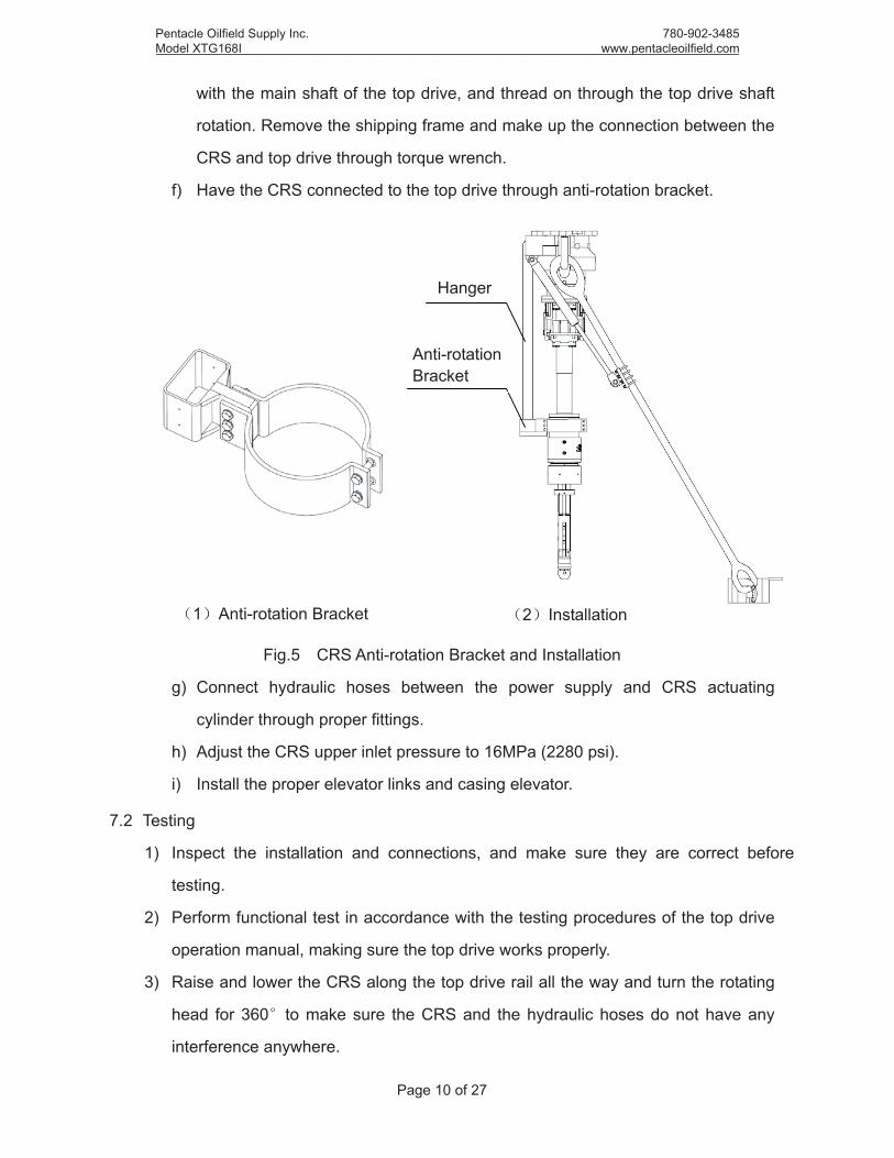
with the main shaft of the top drive, and thread on through the top drive shaft
rotation. Remove the shipping frame and make up the connection between the
CRS and top drive through torque wrench.
f) Have the CRS connected to the top drive through anti-rotation bracket.
Fig.5 CRS Anti-rotation Bracket and Installation
g) Connect hydraulic hoses between the power supply and CRS actuating
cylinder through proper fittings.
h) Adjust the CRS upper inlet pressure to 16MPa (2280 psi).
i) Install the proper elevator links and casing elevator.
7.2 Testing
1) Inspect the installation and connections, and make sure they are correct before
testing.
2) Perform functional test in accordance with the testing procedures of the top drive
operation manual, making sure the top drive works properly.
3) Raise and lower the CRS along the top drive rail all the way and turn the rotating
head for 360 to make sure the CRS and the hydraulic hoses do not have any
interference anywhere.
Hanger
1 Anti-rotation Bracket 2 Installation
Anti-rotation Bracket
Pentacle Oilfield Supply Inc.Model XTG168I _____________________________________________________________________________________
780-902-3485 www.pentacleoilfield.com

Page 11 of 27
4) Open the hydraulic supply, pressure up the upper and lower chamber of the
actuating cylinder, and monitor whether the pressure is normal and the slips can
perform disengaged and engaged function.
5) Rotate the main shaft of the top drive for a few minutes continuously, and see
whether the CRS works properly.
8. Application and Operations
Well completion is a project that requires close coordination and cooperation to
accomplish. From the wellbore quality to the drilliing mud properties, from the well
completion plans to operations, every single step is essential and there will be no
guarantee for quality if any step is problematic. Casing running operation is the most
significant step of all and it will determine the well completion quality.
As it is going to be the first time for some casing crews to run casing with top drive and
casing running equipment, it will be totally different from the conventional casing running
operation. So to ensure a successful casing job, please read the following materials
thoroughly and follow the exact procedures listed here.
8.1 Preparation before Running Casing
Because of the process of the casing job and all the hazards that will be confronted
with, it is important to be able to run the casing continuously. So it is essential to be fully
prepared for the following aspects:
1) Casing preparation, such as making a record of the quantity, specification, size,
and labeling the casing.
2) Surface equipment preparation, such as examining the derrick, crown block, top
drive, braking system, transmission system, pneumatic system, hoisting system,
circulation system, weight indicator, pump pressure indicator, blowout preventer
equipment, electrical equipment and electric circuit, so as to make sure that the
surface equipment works properly. Casing running equipment and the tools should
be in place, and spare parts should be ready.
3) Elevator links preparation, normally 180" elevator links are configured for CRS.
Please user or drilling contractor prepare the proper elevator links for this
application.
Pentacle Oilfield Supply Inc.Model XTG168I _____________________________________________________________________________________
780-902-3485 www.pentacleoilfield.com

Page 12 of 27
4) Wellbore preparation, such as flushing the wellbore based on the design and
drifting with drill bit.
5) Before casing running, drilling supervisor should organize a meeting for
engineering personnel to communicate with the casing crews for technical details,
also make sure the job is clearly assigned, and safety precaution, work standard
and project schedule is clear.
8.2 Casing Running
(1) Casing Job Precautions
a) Take care of the connection thread on the casing, prevent damage or dirt which
could lead to bad connection.
b) Operate smoothly, control the speed when lowering, apply the assited braking
in time. Any abrupt raising, lowering and braking is prohibited.
c) It is prohibited to throw casing protectors from the drill floor to the ground to
avoid injuries. Casing protectors should be collected and send to the ground
with winch.
d) Casing should be centralized before making the connection. Turn the casing
slowly at the beginning, and if there is any sign that the casing cannot be made
up, break out the connection, examine or rework the thread, and then stab the
casing, make up the connection and lower the casing into the wellbore.
e) During make-up, if the casing vibrates too much, the make-up speed should be
slowed down. If the problem still exists, then it might be caused by disalignment
of the axis of the thread and the casing, and this is an indication of quality issue,
therefore the casing should not be run into the wellbore.
f) When lowering the casing, avoid impact load which could lead to casing body,
coupler shoulder and thread damage.
g) When lowering the casing, perform the automatic mud fill-up timely, and if
necessary, inject the drilling mud after each casing is run.
h) When lowering the casing, minimize the inactive time, and move the casing up
and down.
i) When lowering the casing, if stuck casing or other complex situation happens,
Pentacle Oilfield Supply Inc.Model XTG168I _____________________________________________________________________________________
780-902-3485 www.pentacleoilfield.com

Page 13 of 27
take advantage of the top drive, for example, rotate the casing, raise or lower
the casing, circulate the mud and etc. Avoid the situation getting worse, and
ensure a smooth casing running job.
j) There should be assigned personnel to watch and record the drilling mud return,
record the changes of the suspending load, and if there is abnormal situation,
take measures accordingly.
(2) Casing Running Procedure:
a) Field personnel should roll the casing to the catwalk, tie the rope sling to the
casing firmly 1.5m away from the female thread, have the thread protector on
and have it hung from the air hoist, tie down the rope sling.
b) Hoist operator should follow the instructions of the rope sling operator, start the
air winch to tighten the rope sling, wait till the field personnel to step to the
safety zone, bring the casing to the catwalk, stop the movement when the
female thread portion get onto the rig floor for around 2m, the casing operator
remove the casing thread protector and rope sling.
c) Operate the elevator link to forward position so that the casing elevator is close
to the coupler of the casing that will be lowered, then the elevator hold the
casing under the assistance of a rig floor crew, and lock up the elevator.
Fig.6 Have the Casing Held in Elevator
Pentacle Oilfield Supply Inc.Model XTG168I _____________________________________________________________________________________
780-902-3485 www.pentacleoilfield.com

Page 14 of 27
d) Hoist the top drive and the casing, operate elevator link to backward position.
When it returns to the center of the wellbore approximately, operate the
elevator link to neutral position and tilt cylinders will be in unload mode.
Fig.7 Hoist the Casing and Prepare for Connection Make-up
e) Hoist the casing to return it to a center position. Remove the thread protector,
apply casing grease and thread sealant evenly.
f) Tighten up the casing guide shoes with the hydraulic tongs.
g) Driller releases the brake, and the first casing will be set. Repeat the previous
steps to hoist the second casing to a point where its male thread is 0.2m higher
than the female thread of the previous casing segment.
h) Rig crews remove the thread protector, and the driller releases the brake. Stab
carefully to avoid cross threading. Avoid dust or dirt falling into the thread, and
take care of the metal sealing area.
i) After stabbing, operate the "Engage" button, start the CRS to actuate the slips
to grip the casing, and then make up the connection to the specified torque with
Pentacle Oilfield Supply Inc.Model XTG168I _____________________________________________________________________________________
780-902-3485 www.pentacleoilfield.com

Page 15 of 27
the top drive.
j) After the makeup operation, hoist the casing slowly for about 0.2 0.3m before
braking, wait till the power slips of the rotary table releases, then apply the
brake slowly, watch the weight indicator and lower the casing. When the
elevator is about 2m above the rotary table, slow down and make the stop
when the elevator is about 0.5m~1m above the rotary table. Apply the power
slips to grip the casing. Repeat the previous steps to set all the casings into the
wellbore.
Warning: When lowering the casing into the wellbore, before the air slips grip
the casing, do not disengage the casing elevator on the elevator links.
(3) Disassembly of the CRS
a) After the completion of the casing job, disconnect all the piping connections,
fasteners, accessories from the top drive.
Note: Before disassembling the hydraulic hoses, prepare suitable containers,
cotton cloth and oil plugs to avoid the hydraulic oil spill and contaminating the
equipment and surrounding environment.
Warning: Shut off the valves in the system and relieve the system pressure
slowly before disassembling the hydraulic line. Make sure there is no trapped
pressure in the system.
Warning: The hydraulic oil might be hot after operation, so it takes some time
for it to cool down to a level for access.
b) Before disassembly, please mark the assembly positions for the connections
for a correct re-assembly work.
c) After disassembly, please inventory the parts and clean up for repair work or reuse.
Note: After the disassembly, restore the top drive saver sub, retaining
equipment, backup tong, hydraulic hoses and pressure relief valve to the
original condition, making sure a safe application of the top drive next time.
9. Intelligence Aided Equipment
In order to promote the CRS casing job automation and intelligentization, and to ensure
job security and efficiency, devices like travel switch, and video monitoring system have
Pentacle Oilfield Supply Inc.Model XTG168I _____________________________________________________________________________________
780-902-3485 www.pentacleoilfield.com

Page 16 of 27
been integrated into the system design.
9.1 Video Monitoring System
In order to increase the visual monitoring ability
in the casing running process, to decrease the labor
intensity, to monitor the CRS insertion into and lower
the casing, and to ensure the operation precision,
the CRS is equipped with a Video Monitoring System:
a color video camera that is infrared and
explosion-proof is installed on the derrick, a monitor
and a graphics controller are installed in the driller’s
console to achieve point to point video monitoring
(refer to the figure on the right).
The installation height of the video camera should be about the same as the length of a
casing stand above the drill floor. The video camera focus on the casing coupling that is
hoisted, the casing hoisting, CRS lowering and inserting into the casing, slips engaging,
casing rotation, casing string lowering, circulation are under monitoring. The zoom in ability
of the video camera will surpass the eyes of a human for observing closely, so the working
conditions of the slips and the abrasion of the cup packer can all be mastered in time.
10. Maintenance and Repair
A safe and reliable CRS determines whether the casing job will be successful or not
and the benefit. So to ensure a properly working CRS during the casing job, there is
relatively high requirements for the quality level of the routine maintenance and repair work.
Notes: The CRS maintenance should be done in accordance with the requirements, it
will increase the service life of the system and is very important for operation safety.
Warning: The repair quality of the CRS is related to safety and reliability of this product,
so the maintenance personnel must be trained and has valid certification for repair work
from the equipment manufacturer, and written approval needs to be obtained for the repair
work environment. It is strictly prohibited to disassemble the hydraulically actuating section
for maintenance and replace the relevant parts for any company or individual without the
authority and permission from the manufacturer. Otherwise, the maintenance personnel
Pentacle Oilfield Supply Inc.Model XTG168I _____________________________________________________________________________________
780-902-3485 www.pentacleoilfield.com

Page 17 of 27
should take full responsibility of the associated consequences. The normal replacement of
the slips is not covered by this caution, but the repair personnel must be trained, qualified,
and received the repair authority from the manufacturer.
10.1 Routine Inspection and Maintenance
1) Inspection Items:
a) Check if the engage/disengage of the slips is normal.
b) Check if there is any leakage of the hydraulic fluid.
c) Check if there is any loose fasteners or damage of the fasteners.
d) Check the abrasion condition of the seals.
e) Check if there is abnormal condition of the surface-treated locations.
f) Check the locations where grease is needed.
2) Maintenance Items:
a) Remove the oil contamination and foreign matters timely, avoid plugging the
pressure balance orifice on the actuating cylinder.
b) Ensure the fastners are tightened and locked. Replace the damaged parts in time.
Warning: Prevent the fastners from loosening up and hurting someone.
c) There are bearings inside the actuating cylinder and slip coupler, so pump
lithium based grease through the grease nipple and gaps regularly.
d) If there is excessive wear or flake, then it needs repair or replacement.
e) Watch the pressure gauge closely each time setting the casing, if the pressure
is not stable, then it should be disassembled and repaired. In principle, all the
seals and backup rings need to be replaced for each disassembly and repair.
Warning: Avoid the hydraulic fluid leaking, as it might cause injury and slipping
of slips.
Note: After each completion of the casing job by the CRS, inspect each
component carefully; make sure the hydraulic cylinder is working properly and leak free,
and the slips are in good condition. If necessary, disassemble and repair the equipment to
ensure a safe operation.
10.2 Repair Preparation
1) Disassembly and assembly frame, and proper tools (including special tools, pipe
Pentacle Oilfield Supply Inc.Model XTG168I _____________________________________________________________________________________
780-902-3485 www.pentacleoilfield.com

Page 18 of 27
tongs, chain tongs, nylon slings, and etc.).
2) All the lubricants (calcium based grease, lithium based grease, L-HM32 anti-friction
hydraulic oil).
3) Documents associated with the equipment (including the Operation Manual, Seals
Checklist and etc.).
4) Spare parts (including seals, backup rings and etc.).
10.3 Disassembly
Caution During disassembly, it is prohibited to nip the sealing surface and the outer
surface of the thin wall sleeve. There is Y680 bonding agent applied on the connecting
thread between the shaft and slip mandrel (normally, it is not necessary to unthread the
connection between the mandrel and slip mandrel), so before breakout, the thread portion
should be heated to around 250 to break the bond between the parts, then unthread the
connection.
1) Mount the CRS mandrel on the bench clamp of the disassembly breakout machine,
prepare a container for oil collection, use Allen key to remove two hexagon plugs, and drain
the hydraulic oil out of the two chambers.
2) Remove two hex. socket set screws on the stabbing guide with allen key, and then
remove the stabbing guide.
3) Remove three hex. socket set screws on the outer sleeve of the retainer ring with
allen key, then remove the outer sleeve, the leaf spring, retainer ring, inner sleeve.
4) Remove three socket head cap screws on the outer sleeve of the slip coupler with
allen key, and than remove the sleeve, and the split coupler.
5) Remove the bearing housing, thrust ball bearing, slips, thrust ball bearing, and
spacer sequentially.
Caution: The slips may drop out after the constraints have been removed, so take
caution and do not get hurt.
Warning The hydraulic cylinder will be disassembled starting from now, and
unauthorized personnel should not take on this job, otherwise the the relevant personnels
should be responsible for the consequences that followed.
6) Remove the locking wire on the hex head bolt.
Pentacle Oilfield Supply Inc.Model XTG168I _____________________________________________________________________________________
780-902-3485 www.pentacleoilfield.com

Page 19 of 27
7) Remove the hex head bolts and lock washers that are between the upper, lower
cylinder head and the actuating cylinder, and then remove the upper and lower
cylinder head.
8) Use the hoisting strap to remove the actuating cylinder and the piston together
horizontally. Make sure the alignment of the actuating cylinder and mandrel.
9) Tie the hoisting strap to the lower end of the piston, then take the cylinder and
piston apart.
10) Remove the backup ring, lock nut, tapered bearing, spacer, and tapered roller
bearing sequentially from the mandrel.
11) Use the spline sleeve tool to remove the slip mandrel from the top drive shaft.
12) Remove the o-rings, backup rings, wiper rings and wear band from each
component.
13) Flush all the components with cleaning equipment. Inspect all the components
visually for any severe wear or damage. Examine the mandrel, slip mandrel,
actuating cylinder, piston, slips and other important components nondestructively,
and determine whether they need replacements accordingly.
14) All the sealings need to be replaced after each disassembly and repair.
10.4 Assembly
Caution: During assembly, it is prohibited to nip the sealing surface and the outer
surface of the thin wall sleeve. It is also prohibited to use sharp tool for the assembly of
seals. It is recommended to use soft rubber/plastic tools.
1) Remove the components that were rejected after examination, and replace with
new parts. Prepare for a set of backup seals and greasing tools.
Note: Please refer to the instructions in the package for installation location.
2) Actuating System Assembly
a) Mount the mandrel on the bench clamp of the disassembly and assembly frame,
Use the spline sleeve to engage the slip mandrel and mandrel following the
instructions of Table 2.
b) Heat the inner ring of the tapered roller bearing and install it onto the mandrel
(pay attention to the direction), and then install the spacer, and by the same way,
Pentacle Oilfield Supply Inc.Model XTG168I _____________________________________________________________________________________
780-902-3485 www.pentacleoilfield.com

Page 20 of 27
install the other inner ring of the bearing, then install the outer rings of the
bearings from each side.
c) Thread the clamping nut onto the mandrel, and tighten the thread with the
groove on the outiside, make sure the bearing has been pressed tight, and then
install the elastic lock washer. Apply lithium based grease around the bearing.
d) Install the backup ring, o-ring and wear band at the right place, and apply
calcium based grease at the groove.
e) Install the wear band inside the piston Turcon Roto-glyd ring and Turcon
Double Delta Seal Ring, then apply calcium based grease at the groove.
Caution: Ensure each part is clean, and it is prohibited to heat the seals with hot
water.
f) Push the piston assembly slowly into the actuating cylinder, pay attention to the
seals and wear band, make sure it is clean inside the cylinder, the orifices, and
there are no foreign matters in the orifices and injection ports.
3) Slips Assembly
a) Mount the mandrel on the bench clamp of the disassembly and assembly frame,
hoist the actuating cylinder and piston assembly slowly and push the assembly
from the right side of the slip mandrel till the face of the actuating cylinder inner
bore aligns with the face of tapered roller bearing.
b) Install the backup ring, o-ring, backup ring, o-ring, wear band, wiper ring at the
corresponding locations, apply calcium based grease at the groove.
c) Push the lower housing assembly onto the mandrel from the right side, pay
attention to the seals, make sure to align the thread holes of the lower housing
and the actuating cylinder.
d) Slide the spring washer onto the hex head bolt, thread the bolts into the tapped
holes in a diametrically staggered pattern following the instructions of Table 3.
e) Fix the outer housing, and try to rotate the mandrel to make sure the mandrel
can rotate smoothly and easily.
f) Measure and remachine the upper housing to adjust the axial clearance of the
bearing.
g) Install the wiper ring in the upper housing, and push the upper housing
Pentacle Oilfield Supply Inc.Model XTG168I _____________________________________________________________________________________
780-902-3485 www.pentacleoilfield.com

Page 21 of 27
assembly from the left side of the mandrel. Make sure to align the tapped holes
of the upper housing and the actuating cylinder. Apply Loctite 510 at the
interface between the upper housing and the actuating cylinder.
h) Fit the spring washer onto the hex head bolt, thread the bolts into the tapped
holes in a diametrically staggered pattern following the instructions of Table 2.
i) Install the direct injection grease nipple at the corresponding location, and
make sure the orifice is clean and clear.
j) Measure and remachine the spacer to adjust the axial clearance of the thrust
ball bearing.
k) Fix the mandrel, mount the assembly on the bench clamp of the disassembly
and assembly frame, support in the middle if necessary. Install the spacer,
thrust ball bearing from the right side of the slip mandrel (pay attention to the
direction), and then install the slips sequentially into the spline grooves, and
hold them together with iron wire. Install the other thrust ball bearing (pay
attention to the direction, and apply enough lithium based grease), then install
the bearing housing to hold the bearing and slips.
l) Adjust the spacing between the piston and the bearing housing, connect the
piston and the coupler ring with the split type coupler. Slide the sleeve onto the
coupler and fasten with hex. socket set screws following the instructions of
Table 2.
m) Slide the inner sleeve of the retainer ring onto the slips from the right side,
install the four-pieces retainer ring onto the slip mandrel, and install four leaf
springs at the corresponding locations of the retainer ring, then push the inner
sleeve to the right so it touches the retainer ring and make sure the leaf spring
is compressed. Slide the outer sleeve on from the right side, tighten the hex.
socket set screws between the inner sleeve and the outer sleeve in accordance
with the requirements of Table 2.
4) Guideline for Slips, Cup Packer, Stabbing Guide and Seal Cap Selection, Assembly
and Disassembly
a) Based on the specification of the casing (O.D. and Wall Thickness) and refer to
Appendix A, pick the right Slips, Cup Packer, Stabbing Guide and Seal Cap for
Pentacle Oilfield Supply Inc.Model XTG168I _____________________________________________________________________________________
780-902-3485 www.pentacleoilfield.com

Page 22 of 27
the application. The first step is to know the specification of the casing (O.D.
and Wall Thickness), for example, if 7" casing with wall thickness of 11.51mm
will be set, then refer to Appendix A, Slip 9556910146 is selected, then Cup
Packer 5303940220(7B) is the one to pick and the stabbing guide 9556901158
follows, and then Seal Cap 9556902158. Pick these parts in the right order.
b) Apply a thin layer of Calcium Based Grease on the Stabbing Guide Figure 1
shows how the Stabbing Guide and Cup Packer fit together.
1. Stabbing Guide 2. Cup Packer
Fig 8. Cup Packer and Stabbing Guide
c) Refer to Figure 2, install the Seal Cap at the right end of the Slip Mandrel.
Install the O-ring at the left end of the Stabbing Guide, have the Stabbing Guide
threaded to the Slip Mandrel. The Seal Cap now abuts against the Cup Packer.
1. Cup Packer Assembly 2. O-ring 3. Slip Mandrel
Fig 9. Illustration for Assembly of the Stabbing Guide and Cup Packer
d) Have the Set Screws threaded to the Slip Mandrel. The dog point sets into the
groove in the Stabbing Guide for anti-loosening.
Part No.
Part No.
Pentacle Oilfield Supply Inc.Model XTG168I _____________________________________________________________________________________
780-902-3485 www.pentacleoilfield.com

Page 23 of 27
e) For disassembly, reverse the procedures above.
5) Assembly Completion
a) Plug the tapped holes on the actuating cylinder with blanking plugs, tighten the
plugs manually.
b) Keep the hex head bolts from getting loose by using the iron wire to hold the
bolts circumferentially.
c) Inject bearing grease for the tapered roller bearing with grease gun till the
chamber is full. The assembly is complete now.
Notes: All the thread connections are to be tightened with grease and to the specified
torque values according to Table 2.
Table 2 CRS Thread Connection Torque (kN·m) and Grease
Model
Thread
XTG140 XTG168 XTG244
Torque Additive Torque Additive Torque Additive
Mandrel Thread 62 Loctite 680 62 Loctite 680 62 Loctite 680
Bolt Thread 0.33 Loctite 243 0.33 Loctite 243 0.33 Loctite 243
Screw Thread Manually Tighten MoS2 Grease Manually Tighten MoS2 Grease Manually Tighten Loctite 243
Other Thread Manually Tighten MoS2 Grease Manually Tighten MoS2 Grease Manually Tighten MoS2 Grease
Pentacle Oilfield Supply Inc.Model XTG168I _____________________________________________________________________________________
780-902-3485 www.pentacleoilfield.com
Page 24 of 27
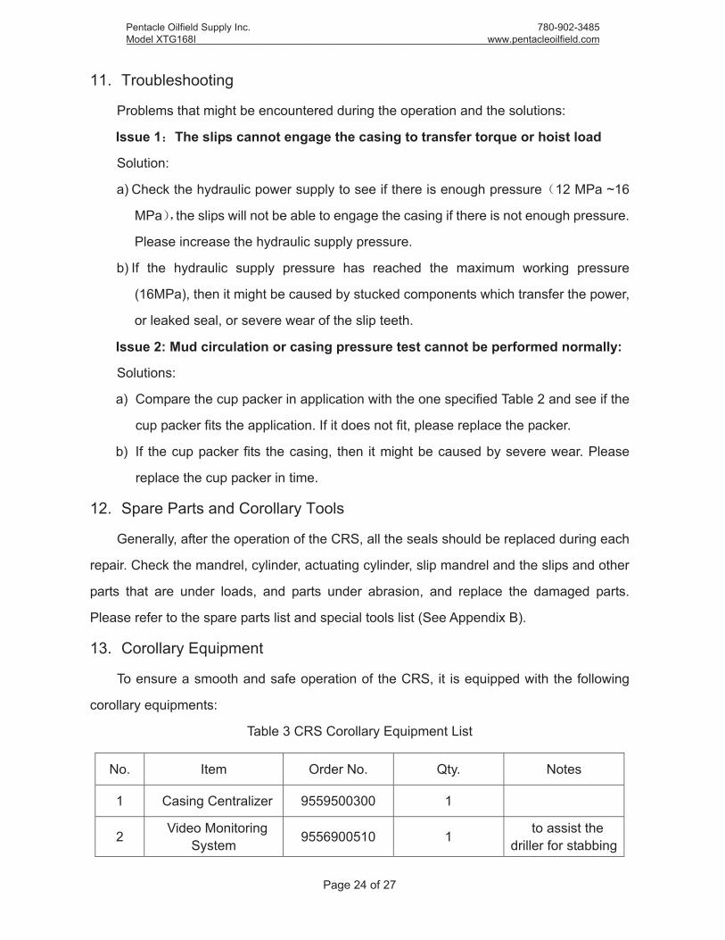
11. Troubleshooting
Problems that might be encountered during the operation and the solutions:
Issue 1 The slips cannot engage the casing to transfer torque or hoist load
Solution:
a) Check the hydraulic power supply to see if there is enough pressure 12 MPa ~16
MPa the slips will not be able to engage the casing if there is not enough pressure.
Please increase the hydraulic supply pressure.
b) If the hydraulic supply pressure has reached the maximum working pressure
(16MPa), then it might be caused by stucked components which transfer the power,
or leaked seal, or severe wear of the slip teeth.
Issue 2: Mud circulation or casing pressure test cannot be performed normally:
Solutions:
a) Compare the cup packer in application with the one specified Table 2 and see if the
cup packer fits the application. If it does not fit, please replace the packer.
b) If the cup packer fits the casing, then it might be caused by severe wear. Please
replace the cup packer in time.
12. Spare Parts and Corollary Tools
Generally, after the operation of the CRS, all the seals should be replaced during each
repair. Check the mandrel, cylinder, actuating cylinder, slip mandrel and the slips and other
parts that are under loads, and parts under abrasion, and replace the damaged parts.
Please refer to the spare parts list and special tools list (See Appendix B).
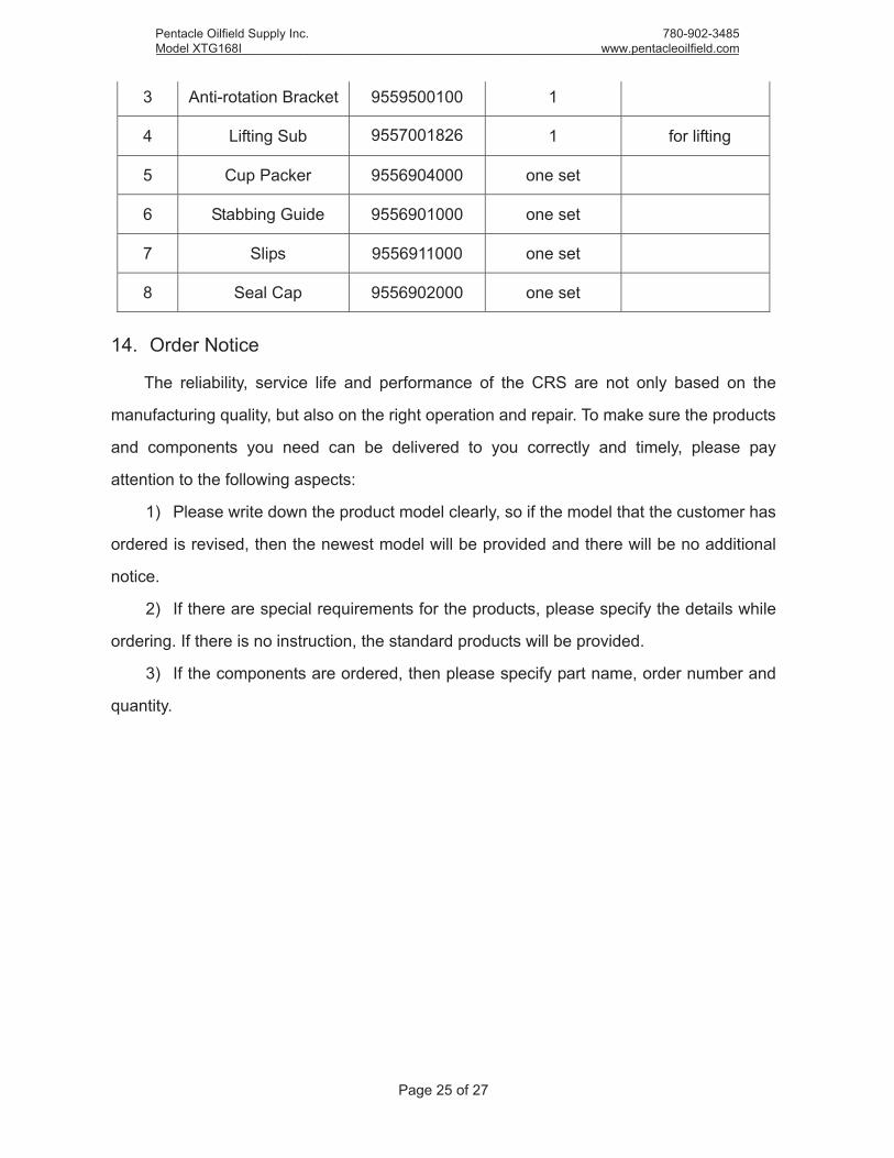
13. Corollary Equipment
To ensure a smooth and safe operation of the CRS, it is equipped with the following
corollary equipments:
Table 3 CRS Corollary Equipment List
No. Item Order No. Qty. Notes
1 Casing Centralizer 9559500300 1
2 Video Monitoring System 9556900510 1 to assist the
driller for stabbing
Pentacle Oilfield Supply Inc.Model XTG168I _____________________________________________________________________________________
780-902-3485 www.pentacleoilfield.com
Page 25 of 27
3 Anti-rotation Bracket 9559500100 1
4 Lifting Sub 9557001826 1 for lifting
5 Cup Packer 9556904000 one set
6 Stabbing Guide 9556901000 one set
7 Slips 9556911000 one set
8 Seal Cap 9556902000 one set
14. Order Notice
The reliability, service life and performance of the CRS are not only based on the
manufacturing quality, but also on the right operation and repair. To make sure the products
and components you need can be delivered to you correctly and timely, please pay
attention to the following aspects:
1) Please write down the product model clearly, so if the model that the customer has
ordered is revised, then the newest model will be provided and there will be no additional
notice.
2) If there are special requirements for the products, please specify the details while
ordering. If there is no instruction, the standard products will be provided.
3) If the components are ordered, then please specify part name, order number and
quantity.
Pentacle Oilfield Supply Inc.Model XTG168I _____________________________________________________________________________________
780-902-3485 www.pentacleoilfield.com

Pag
e 26
of 2
7
App
endi
x A
Slip
s, C
up P
acke
r, S
tabb
ing
Gui
de a
nd S
eal C
ap S
elec
ting
Gui
de
Cas
ing
Spe
cifa
ctio
n Sel
ecting
CRS C
ompo
nent
s
Siz
e O
.D.
Wal
lTh
ick
I.D
.D
rift
Dia
.Slip
s Cup
Pac
ker
Sta
bbin
g G
uide
Sea
l Cap
6-5/
816
8.28
7.32
153.
6415
0.46
9556
9101
4653
0394
0220
(7B
) 95
5690
1158
95
5690
2158
6-
5/8
168.
288.
9415
0.40
147.
227
177.
805.
8716
6.06
162.
88
9556
9101
5853
0394
0210
(7A
)
9556
9011
58
9556
9021
58
717
7.80
6.91
163.
9816
0.80
717
7.80
8.05
161.
7015
8.52
717
7.80
9.19
159.
4215
6.24
717
7.80
10.3
615
7.08
153.
90
9556
9101
4653
0394
0220
(7B
) 7
177.
8011
.51
154.
7815
1.60
717
7.80
12.6
515
2.50
149.
327
177.
8013
.72
150.
3614
7.18
7-5/
819
3.68
7.62
178.
4417
5.26
9556
9101
7853
0394
0430
(75A
) 95
5690
1178
95
5690
2178
7-
5/8
193.
688.
3317
7.02
173.
847-
5/8
193.
689.
5217
4.64
171.
467-
5/8
193.
6810
.92
171.
8416
8.66
9556
9101
58
5303
9404
40 (7
5B)
7-5/
819
3.68
12.7
168.
2816
5.10
7-5/
819
3.68
14.2
716
5.14
161.
9653
0394
0210
(7A
) 95
5690
1158
95
5690
2158
7-
5/8
193.
6815
.11
163.
4616
0.28
7-5/
819
3.68
15.8
816
1.92
158.
747-
5/8
193.
6817
.45
158.
7815
5.60
5303
9404
50 (7
5C)
7-5/
819
3.68
19.0
515
5.58
152.
4095
5691
0146
Pen
tacl
e O
ilfie
ld S
uppl
y In
c.M
odel
XTG
168I
____
____
____
____
____
____
____
____
____
____
____
____
____
____
____
____
____
____
____
____
____
_
78
0-90
2-34
85
ww
w.p
enta
cleo
ilfie
ld.c
om

Pag
e 27
of 2
7
App
endi
x A
: Slip
s, C
up P
acke
r, St
abbi
ng G
uide
and
Sea
l Cap
Sel
ectin
g G
uide
Cas
ing
Spe
cific
atio
n Sel
ecting
CRS C
ompo
nent
s
Siz
e O
.D.
Wal
lTh
ick
I.D
.D
rift
Dia
.Slip
s Cup
Pac
ker
Sta
bbin
g G
uide
Sea
l Cap
7-3/
419
6.85
15.1
116
6.63
163.
4595
5691
0158
5303
9404
40 (7
5B)
9556
9011
7895
5690
2178
8-5/
821
9.08
6.71
205.
6620
2.48
9556
9101
9853
0394
0400
(9D
) 95
5690
1198
9556
9021
988-
5/8
219.
087.
7220
3.64
200.
468-
5/8
219.
088.
9420
1.20
198.
02
9556
9101
8853
0394
0410
(8A
) 95
5690
1188
9556
9021
888-
5/8
219.
0810
.16
198.
7619
5.58
8-5/
821
9.08
11.4
319
6.22
193.
048-
5/8
219.
0812
.70
193.
6819
0.50
5303
9404
20 (8
B)
8-5/
821
9.08
14.1
519
0.78
187.
609-
5/8
244.
487.
9222
8.64
224.
66
9556
9102
1553
0394
0240
(9A
)
9556
9012
1595
5690
2215
9-5/
824
4.48
8.94
226.
6022
2.63
9-5/
824
4.48
10.0
322
4.42
220.
459-
5/8
244.
4811
.05
222.
3821
8.41
5303
9402
50 (9
B)
9-5/
824
4.48
11.9
922
0.50
216.
549-
5/8
244.
4813
.84
216.
8021
2.83
9556
9101
98
9-5/
824
4.48
15.1
121
4.26
210.
2953
0394
0390
(9C
) 95
5690
1198
9556
9021
989-
5/8
244.
4815
.47
213.
5420
9.58
9-5/
824
4.48
17.0
721
0.34
206.
389-
5/8
244.
4818
.64
207.
2020
3.23
5303
9404
00 (9
D)
9-5/
824
4.48
20.2
420
4.00
200.
02
Pen
tacl
e O
ilfie
ld S
uppl
y In
c.M
odel
XTG
168I
____
____
____
____
____
____
____
____
____
____
____
____
____
____
____
____
____
____
____
____
____
_
78
0-90
2-34
85
ww
w.p
enta
cleo
ilfie
ld.c
om

Page 28 of 27
Appendix B Spare Parts and Corollary Tools
1 XTG168 Spare Parts List
No. Part Name Model Part No. Qty. Notes
1.1 7" Casing Cup Packer
7A 5303940210 1 covering 6-5/8casing7B 5303940220 1
1.2 7-5/8" Casing Cup Packer
75A 5303940430 1 covering 7-3/4
casing75B 5303940440 1 75C 5303940450 1
1.3 8-5/8" Casing Cup Packer
8A 5303940410 1 8B 5303940420 1
1.4 9-5/8" Casing Cup Packer
9A 5303940240 1 9B 5303940250 1 9C 5303940390 1 9D 5303940400 1
1.5 Slip 9556910146 1
1.6 Slip 9556910158 1
1.7 Slip 9556910178 1
1.8 Slip 9556910188 1
1.9 Slip 9556910198 1
1.10 Slip 9556910215 1
1.11 Thrust Ball Bearing 9557001200 2
1.12 Hex. Socket Cap Screw 4202300010 8
1.13 Hex. Socket Set Screw 4201030840 2
1.14 Hydraulic Hoses 9556900008 6 1m
1.15 Seals Pack 9556900900 1 one set
2 Corollary Tools
No. Part Name Model Part No. Qty. Notes 2.1 Corollary Tools 9556900913 1
Pentacle Oilfield Supply Inc.Model XTG168I _____________________________________________________________________________________
780-902-3485 www.pentacleoilfield.com