pennsylvania state urban hydrology model as a tool for...
TRANSCRIPT
36 TRANSPORTATION RESEARCH RECORD 1279
Pennsylvania State Urban Hydrology Model as a Tool for Highway Drainage Design
THOMAS A. SEYBERT AND DAVID F. KIBLER
The capabilities of the Pennsylvania State Urban Hydrology Model are presented. he mode.I contains 17 subprograms that perform various hydrologic and hydraulic operations, which include curve n 1 1 er •e.ighting, tra •el tirm: swale design, hydrograph combining graphic. plorting, rninfall calculations, Soil Conservation Service ( ) unit hydrograph , tabular hydrograpb , modiri~u rntional hyurograph Muskingum chann I routing, modified Puls routing, and multiple-stage outlet ana ly is. The model operates on an rBM personal computer or compatible and is menu driven. An example is presented to illustrate l'he use of the model.
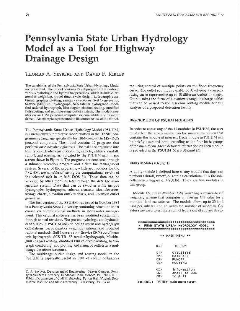
The Pennsylvania State Urban Hydrology Model (PSUHM) is a mt:nu-driven interactive model written in the BASIC programming language specifically for IBM-compatible MS-DOS personal computers. The model contains 17 programs that perform various hydrologic tasks . The tasks are organized into four types of hydro logic operations; namely, utilities, rainfall, runoff, and routing, as indicated by the PSUHM main menu screen shown in Figure 1. The programs are connected through a submenu selection program and a data file management system. Several of the programs, which are modules for the PSUHM, are capable of saving the computational results of the selected task in an MS-DOS file. These data can be m.:1.:essed by other modules later through the data file management system. Data that can be saved as a file include hyetographs, hydrographs, subarea characteristics, elevationstorage charts, elevation-outflow charts, and detention outlet geometry.
The first version of the PSUHM was issued in October 1984 in a Pennsylvania State University continuing education short course on computational methods in stormwater management. This original software has been modified substantially through annual revisions. The present hydrologic and hydraulic capabilities in PSUHM include design storm and hyetograph calculations, curve number weighting, rational and modified rational methods, Soil Conservation Service (SCS) curvilinear unit hydrograph, SCS TR-55 tabular hydrograph , Muskingum channel routing, modified Puls reservoir routing, hydrograph combining, and plotting and sizing of outlets in a multistage detention structure.
The multistage outlet design and routing model in the PSUHM is especially useful in light of recent ordinances
T. A. Seybert, Department of Engineering, Beaver Campus, Pennsylvania State University, Brodhead Road, Monaca, Pa . 15061. D. F. Kibler, Department of Civil Engineering, Patton Hall, Virginia Polytechnic Institute and State University, Blacksburg, Va . 24061.
requiring control of multiple points on the flood frequency curve. The outlet routine is capable of developing a complex rating curve representing up to 10 different outlets or stages. Output takes the form of elevation-storage-discharge tables that can be passed to the reservoir routing module for full analysis of a proposed detention facility.
DESCRIPTION OF PSUHM MODULES
In order to access any of the 17 modules in PSUHM, the user must select the group nu111be1 011 Lile main mt:nu s<.:reen that contains the module of interest. Each module in PSUHM will be briefly described here according to the four basic groups of the main menu. More detailed information on each module is provided in the PSUHM User's Manual (1).
Utility Modules (Group 1)
A utility module is defined here as any module that does not perform rainfall, runoff, or muting calculations. It is the miscellaneous category of PSUHM. There are five modules in this group.
Module lA. Curve Number (CN) Weighting is an area-based weighting scheme that computes an average CN value for a multiple-land use subarea. The module allows up to 20 land uses per subarea and an unlimited number of subareas. CN values are used to estimate runoff from rainfall and are <level-
******•******************************* * PENN STATE URBAN HYDROLOGY MODEL * **************************************
** MAIN MENU **
HIT TO RUN
<1> UTILITIES <2> RAINFALL <3> RUNOFF <4> ROUTING
<I> information <D> shell to DOS <Q> to QUIT
FIGURE 1 PSUHM main menu screen.
Seybert and Kibler
oped by the SCS as described in the SCS Technical Release 55 (TR-55) (2).
Module lB. Travel Time Calculation will solve various travel time equations that are listed in the module's travel time menu. This module features the SCS segmental approach to travel time calculation from TR-55 (2). Other equations solved in this module are the average velocity charts in the 1975 TR-55 (J), the Federal Aviation Administration (FAA) overland flow equation, the kinematic wave equation, Manning's equation for pipe or channel flow, and the SCS basin lag equation. These single quations are summarized in the American Geophysical Union (AGU) Water Resources Monograph No. 7 (4).
Module lC. Hydrograph Combination will add two hydrographs together, as in the case of a confluence point in a stream network. The new hydrograph can be saved in a data file.
Module 1 D. Data File Plotting uses screen graphics to display the contents of one or two data files of the same type for comparative analysis. Hyetographs, hydrographs, elevationstorage, and elevation-outflow files may be plotted on the display. The screen display can be sent to the printer.
Module lE. Swale Design uses a Newton-Raphson scheme to solve Manning's equation for a trapezoidal channel. The user can specify depth and solve for flow or specify flow and solve for depth. A report of several hydraulic parameters of the swale is provided, including a recommended rip-rap for bed stability.
Rainfall Modules (Group 2)
Five rainfall modules are available in PSUHM. Every module creates a hyetograph that can be stored and used in conjunction with the Unit Hydrograph Module 3A.
Module 2A. Composite Storm by U.S. Weather Bureau IDF Curves will create a synthetic hyetograph for a specified return period, on the basis of the U.S. Weather Bureau' standard intensity-duration-frequency (IDF) curves as developed by Yarnell (5). The storm is central peaking, limited to a maximum length of 120 min and minimum step of 5 min.
Module 2B. SCS Type II Scaled Rainfall Distribution will create a synthetic hyetograph according to th SCS Type II rainfall distribution. Thi. di iribution is defined in TR-55 (2) . The duration of the storm can be any length from 0 to 24 hr and the step can be any practical value, in hours. Design storms shorter than the Type II standard of 24 hr are scaled to include the most intense portion of the 24-hr distribution.
Module 2C. SCS Type III Scaled Rainfall Distribution works exactly the same as the Type TI Module 2B , except it u e ' the Type UI rainfall di tr.ibution a.I o de cribed in TR-55 (2) .
Module 20. omposite S1orm by Pe1111sy/v(l11ia DOT- IDF Curves works practically identical to Module 2A except that it uses rainfall curves developed specifically for Pennsylvania as given by Aron (6) . Use is limited to Pennsylvania and neighboring areas.
Module 2E. Manual Entry of a Hyetograph will allow the user to enter a design storm or observed storm of any duration and any time step. The storm can contain up to 101 data points.
37
Runoff Modules (Group 3)
The runoff modules contain methods that create complete runoff hydrographs for a given watershed or subarea. The TR-55 methods in Module 3B were designed to create partial hydrographs; however, for most small watersheds the hydrographs produced will be sufficiently complete.
Module 3A. Subarea Hydrographs by SCS Unit Hydrograph will create a hydrograph based on the SC curvilinear uni t hydrograph discussed in the SCS National Engineering Handbook, Section 4 (7). A design storm created through one of the rainfall modules in Group 2 acts as the input to this subprogram. Along with the runoff hydrograph, periods of rainfall excess and the unit hydrograph are presented. The method is general and no limit is placed on watershed size.
Module 3B. SCS TR-55 Tabular Hydrograph will create a hydrograph using the 19 6 tabular method found in Chapter 5 of TR- 55 (2). The method is based on the SCS TR- 20 runoff program and is an approximate method for developing a hydrograph for a watershed composed of several subareas. In addition to a complete hydrograph, this module generates a summary screen that shows runoff contributions of each subarea to the peak flow in the composite hydrograph. The method is limited to areas with times of concentration less than 2 hr, but greater than 0.1 hr.
Module 3C. Hydrograph by Modified Rational Method will create a simple yet useful hydrograph for small areas (0 to 20 acres) with uniform land u e. The method use the Pennsylvania Department of Tran ·portation IDF cu.rves (6) to create a skewed hyetograph with time base equal to 11 times the subarea time of concentration. The program then utilizes the rational formula (Q = ciA) by multiplying each ordinate of the hyetograph by cA to create a hydrograph. The program also has an opti0n that allows the user toe ·timare the required detention pond size for a given design release rate .
Module 3D. Manual Entry of Hydrograph will allow the entry of an observed or created hydrograph (up to 101 point ·) to be used with other PSUHM module uch a Module 4B Modified Puls Routing.
Routing Modules (Group 4)
The routing modules will pass a given hydrograph through a detention structure or channel reach and examine the effects on the hydrograph. PSUHM contains three routing modules.
Module 4A. Muskingum Channel Routing is a hydrologic procedure that rout s a hydrograph through a channel reach. It is approximate and i based on the principle of ma s continuity and a storage flow relation. The method i described in most hydrology text , such as Viessman et al. (8) . The module checks to ensure that the routing procedure is numerically stable and that the proper number of subreaches is used .
Module 4B. Modified Puls Ro1.11i11g will route a hydrograph through a reservoir using the torage indication method also described in Vies man et al. (8). This method is based on mass conservation principles and the hydraulics of the reservoir outlet structure. The user must develop and enter two curves: a storage-elevation curve from basin contour data and
38
a discharge-elevation curve from the hydraulics of the outlet configuration. The storage-elevation and discharge-elevation curves can be stored in a file and used again for other runoff situations. The storage-elevation and discharge-elevation curves can be developed in Module 4C.
Module 4C. Multiple Stage Routing Model (MSRM) will route a hydrograph through a multiple outlet detention facility. Written by Chamberlain (9), the model contains a subroutine thal will compute the hydraulic performance curve;: for an outlet structure with up to 10 openings or tages. Th i capability is useful when trying to reduce runoff peaks for several return periods through the use of one structure. The subroutine can model rectangular, v-notch and proportional weirs, perforated risers, emergency spillways, circular and rectangular orifices, open and grated drop inlets, discharge pipes, outfall cu lverts, anu uulfall channels. MSRM will adjust outlet capacity for riser box submergence and for inlet-outlet control in the outfall culvert.
APPLICATIONS OF PSUHM
The software package has an interactive structure that allows it to model an infinite number of hydrologic situations. The user must decide on a sequence of hydrologic operations necessary to solve the problem at hand and then select the appropriate modules from the model to complete the task. On se.lection of a given module, the subprogram will prompt the user to enter the required information for completing the module task. On task completion, the user is returned to the main menu for the next task selection. This process is repeated until the sequence of desired operations is completed.
The following example will illustrate the use and interactive structure of PS UHM. This example consists of a hypothetical design based on an actual watershed and highway-stream crossing in Pennsylvania.
PROTECTING A HIGHWAY CROSSING IN THE WHISKEY RUN WATERSHED
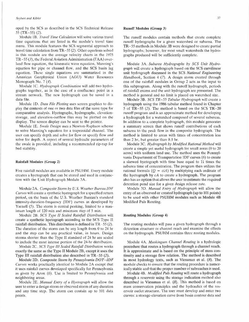
A highway crossing at Whiskey Run located along old Route 28 in East Franklin Township, Armstrong County, Pennsylvania, contains a 50-ft, 6- x 6-fl box culvert that was built in 1925 to control the 25-year flood. Under full-flow conditions, the culvert capacity is 440 ft3/sec, assuming submergeu outlet with head of 4.0 ft. The watershed area of 645 acres above the culvert is shown in Figure 2. Since 1925, the area above the culvert has developed from an agricultural watershed to a single-family residential watershed. Highway flooding at the culvert has been observed on numerous occasions. The flooding condition could be corrected by the construction of a stormwater detention facility within the contributing watershed. In addition to correcting the roadway flooding condition, the detention facility should also be designed to protect the downstream receiving channel from erosion by reducing the 5-year flood peak back to the 2-year flood peak.
Thus the 2- and 25-year events (Q2 and Q25) are chosen as the levels for stream channel and highway crossing protection. PSUHM has been used to design a detention facility that will meet release targets of Q2 and Q25 from Subarea
TRANSPORTATION RESEARCH RECORD 1279
FLOW PATH l~NTIFICATION
0 - Suboreo I 14 SeQments)
Q - Suboreo 2 ( 3 Segments)
FIGURE 2 Sketch of Whiskey Run watershed.
Channel
1. The first step is to analyze runoff peaks and volumes for Q2, Q5, and Q25 so that the basin release targets can be set.
Assembling Physical Data for Whiskey Run Watershed
The engineer must collect watershed physical information before using PSUHM as a runoff model. In this case involving a sizeable watershed, it is reasonable to use the SCS tabular hydrograph module in PSUHM. The necessary information include water hed area, land u e types, hydrologic soil group. (HSG) for each land use, and travel times along critical runoff flow paths.
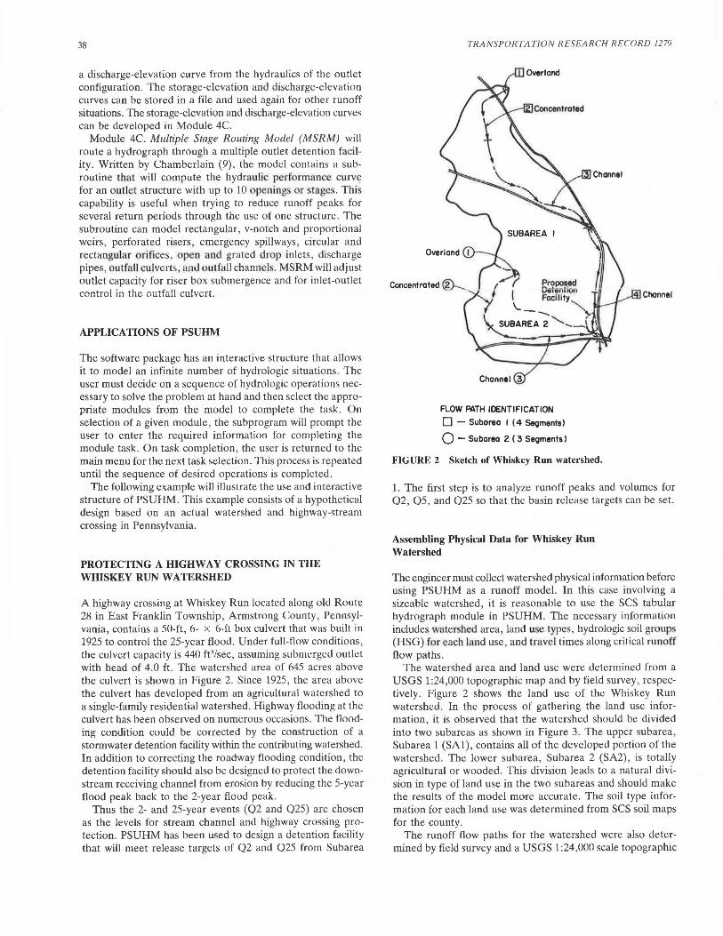
The watershed area and land use were determined from a USGS 1:24,000 topographic map and by field survey , respectively. Figure 2 shows the land use of the Whiskey Run watershed. In the process of gathering the land use information, it is observed that the watershed should be divided into two subareas as shown in Figure 3. The upper subarea, Subarea 1 (SAl), contains all of the developed portion of the watershed. The lower subarea, Subarea 2 (SA2), is totally agricultural or wooded. This division leads to a natural division in type of land use in the two subareas and should make the results of the model more accurate. The soil type information for each land use was determined from SCS soil maps for the county.
The runoff flow paths for the watershed were also determined by field survey and a USGS 1:24,000 scale topographic
Seyberl and Kibler
Ben Franklin Hiohway
LEGEND : Hiohway Stream
C:J Wooded Area
~ Commercial Area
k.'.:Z:::~2 Residential Area
j:::::( Bridoe - Culvert
FIGURE 3 Subarea definition and detention facility location.
map. Several flow paths were investigated to determine which flow path was critical, that is, which flow path had the longest travel time.
Estimating Runoff and Designing a Detention Facility
With the drainage area, land use, and travel time information, the runoff hydrographs for Whiskey Run watershed can be generated. The appropriate steps would be as follows:
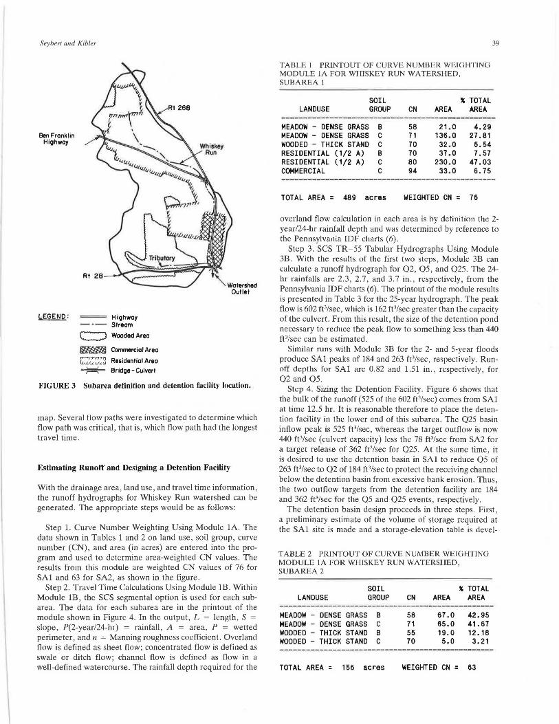
Step 1. Curve Number Weighting Using Module lA. The data shown in Tables 1 and 2 on land use, soil group, curve number (CN), and area (in acres) are entered into the program and used. to determine area-weighted CN values. The results from this module are weighted CN values of 76 for SAl and 63 for SA2, as shown in the figure.
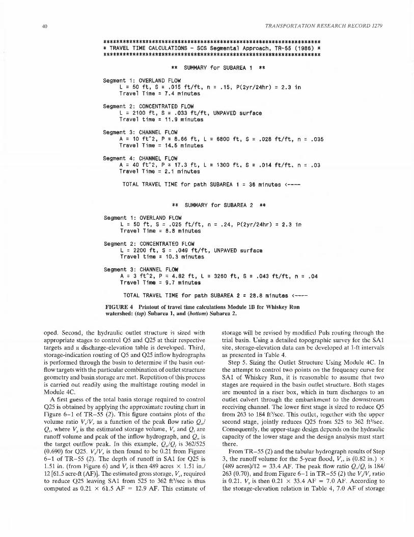
Step 2. Travel Time Calculations Using Module lB. Within Module lB, the SCS segmental option is used for each subarea. The data for each subarea are in the printout of the module shown in Figure 4. In the output, L = length, S = slope, P(2-year/24-hr) = rainfall, A = area, P = wetted perimeter, and n = Manning roughness coefficient. Overland flow is defined as sheet flow; concentrated flow is defined as swale or ditch flow; channel flow is defined as flow in a well-defined watercourse. The rainfall depth required for the
TABLE 1 PRINTOUT OF CURVE NUMBER WEIGHTING MODULE lA FOR WHISKEY RUN WATERSHED, SUBAREA 1
LAN DUSE SOIL GROUP CN
' TOTAL AREA AREA
39
------------------------------------------------MEADOW - DENSE GRASS B 58 21.0 4.29 MEADOW - DENSE GRASS c 71 136.0 27.81 WOODED - THICK STAND c 70 32.0 6.54 RESIDENTIAL (1/2 A) B 70 37.0 7.57 RESIDENTIAL (1/2 A) c 80 230.0 47.03 Cot4MERCIAL c 94 33.0 6.75
TOTAL AREA = 489 acres WEIGHTED CN = 76
overland flow calculation in each area is by definition the 2-year/24-hr rainfall depth and was determined by reference to the Pennsylvania IDF charts (6).
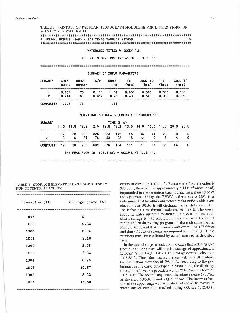
Step 3. SCS TR-55 Tabular Hydrographs Using Module 3B. With the results of the first two steps, Module 3B can calculate a runoff hydrograph for Q2, Q5, and Q25. The 24-hr rainfalls are 2.3, 2.7, and 3.7 in., respectively, from the Pennsylvania IDF charts (6). The printout of the module results is presented in Table 3 for the 25-year hydrograph. The peak flow is 602 ft3/sec, which is 162 ft 3/sec greater than the capacity of the culvert. From this result, the size of the detention pond necessary to reduce the peak flow to something less than 440 ft3/sec can be estimated.
Similar runs with Module 3B for the 2- and 5-year floods produce SAl peaks of 184 and 263 ft 3/sec, respectively. Runoff depths for SAl are 0.82 and 1.51 in., respectively, for Q2 and Q5.
Step 4. Sizing the Detention Facility. Figure 6 shows that the bulk of the runoff (525 of the 602 ft3/sec) comes from SAl at time 12.5 hr. It is reasonable therefore to place the detention facility in the lower end of this subarea. The Q25 basin inflow peak is 525 ft3/sec, whereas the target outflow is now 440 ft3/sec (culvert capacity) less the 78 ft3/sec from SA2 for a target release of 362 ft3/sec for Q25. At the same time, it is desired to use the detention basin in SAl to reduce Q5 of 263 ft3/sec to Q2 of 184 ft3/sec to protect the receiving channel below the detention basin from excessive bank erosion. Thus, the two outflow targets from the detention facility are 184 and 362 ft3/sec for the Q5 and Q25 events, respectively.
The detention basin design proceeds in three steps. First, a preliminary estimate of the volume of storage required at the SAl site is made and a storage-elevation table is devel-
TABLE 2 PRINTOUT OF CURVE NUMBER WEIGHTING MODULE lA FOR WHISKEY RUN WATERSHED, SUBAREA 2
LAN DUSE SOIL GROUP
MEADOW - DENSE GRASS B MEADOW - DENSE GRASS C WOODED - THICK STAND B WOODED - THICK STANO C
TOTAL AREA = 156 acres
CN
58 71 55 70
' TOTAL AREA AREA
67 .0 65.0 19.0 5.0
42.95 41. 67 12.16 3.21
WEIGHTED CN = 63
40 TRANSPORTATION R ESEA RCH RECORD 1279
******************************************************************* * TRAVEL TIME CALCULATIONS - SCS Segmental Approach, TR-55 (1986) * *******************************************************************
** SUMMARY for SUBAREA 1 ** Segment 1: OVERLAND FLOW
L = 50 ft, S = .015 ft/ft, n = .15, P(2yr/24hr) = 2.3 in Travel Time= 7.4 minutes
Segment 2: CONCENTRATED FLOW L = 2100 ft, S = .033 ft/ft, UNPAVED surface Travel time = 11.9 minutes
Segment 3: CHANNEL FLOW A = 10 ftA2, P = 8.66 ft, L = 6800 ft, S = .028 ft/ft, n = .035 Travel Time = 14.5 minutes
Segment 4: CHANNEL FLOW A = 40 ftA2, P = 17.3 ft, L = 1300 ft, s = .014 ft/ft, n = .03 Travel Time= 2.1 minutes
TOTAL TRAVEL TIME for path SUBAREA = 36 minutes <----
** SUMMARY for SUBAREA 2 **
Segment 1: OVERLAND FLOW L = 50 ft, s = .025 ft/ft, n = .24, P(2yr/24hr) = 2.3 in Travel Time = 8.8 minutes
Segment 2: CONCENTRATED FLOW L = 2200 ft, S = .049 ft/ft, UNPAVED surface Travel time = 10.3 minutes
Segment 3: CHANNEL FLOW A = 3 ftA2, P = 4.82 ft, L = 3260 ft, s = .043 ft/ft, n = .04 Travel Time= 9.7 minutes
TOTAL TRAVEL TIME for path SUBAREA 2 = 28.8 minutes <----
FIGURE 4 Printout of ti·avel time calculations Module 1D for Whiskey Run watershed: (top) Subarea 1, and (bottom) Subarea 2.
oped. Second, the hydraulic outlet structure is sized with appropriate stages to control Q5 and Q25 at their respective targets and a discharge-elevation table is developed. Third , storage-indication routing of Q5 and Q25 inflow hydrographs is performed through the basin to determine if the basin outflow targets with the particular combination of outlet structure geometry and basin storage are met. Repetition of this process is carried out readily using the multistage routing model in Module 4C.
storage will be revised by modified Puls routing through the trial basin. Using a detailed topographic survey for the SAl site, storage-elevation data can be developed at 1-ft intervals as presented in Table 4.
Step 5. Sizing the Outlet Structure Using Module 4C. In the attempt to control two points on the frequency curve for SAl of Whiskey Run , it is reasonable to assume that two stages are required in the basin outlet structure. Both stages are mounted in a riser box, which in tum discharges to an outlet culvert through the embankment to the downstream receiving channel. The lower first stage is sized to reduce Q5 from 263 to 184 ft1/scc. This outlet, together with the upper second stage, jointly reduces Q25 from 525 to 362 ft 3/sec. Consequently, the upper-stage design depends on the hydraulic capacity of the lower stage and the design analysis must start there.
A first guess of the total basin storage required to control Q25 is obtained by applying the approximate routing chart in figure 6-1 of TR-55 (2). This figure contains plots of the volume ratio V,IV, as a function of the peak flow ratio Qj Q1, where Vs is the estimated storage volume, V, and Q1 are runoff volume and peak of the inflow hydrograph, and Q0 is the target outflow peak. In this example, Q)Q1 is 362/525 (0.690) for Q25. Vs/V, is then found to be 0.21 from Figure 6-1 of TR-55 (2) . The depth of runoff in SAl for Q25 is 1.51 in. (from Figure 6) and V, is then 489 acres x 1.51 in ./ 12 [61.5 acre-ft (AF)]. The estimated gross storage, V,, required to reduce Q25 leaving SAl from 525 to 362 ft3/sec is thus computed as 0.21 x 61.5 AF = 12.9 AF. This estimate of
From TR-55 (2) and the tabular hydrograph results of Step 3, the runoff volume for the 5-year flood, V,, is (0.82 in .) x (489 acres)/12 = 33.4 AF. The peak flow ratio Q) Q; is 184/ 263 (0.70), and from Figure 6-1 in TR-55 (2) the V/ V, ratio is 0.21. Vs is then 0.21 x 33.4 AF = 7.0 AF. According to the storage-elevation relation in Table 4, 7.0 AF of storage
Seybert and Kibler
TABLE 3 PRINTOUT OF TABULAR HYDROGRAPH MODULE 3B FOR 25-YEAR STORM OF WHISKEY RUN WATERSHED
******************************************************************************** * PSUHM: MODULE <3-B> - SCS TR-55 TABULAR METHOD * ********************************************************************************
WATERSHED TITLE: WHISKEY RUN
25 YR. STORM: PRECIPITATION= 3.7 1n.
===============================================================================
SUBAREA
1 2
AREA (scimi)
0. 764 0.244
COMPOSITE 1.008
SUMMARY OF INPUT PARAMETERS
CURVE IA/P NUMBER
76 63
73
0.171 0.317
RUNOFF (1n)
1. 51 0.76
1. 33
TC (hrs)
0.600 0. 480
ADJ. TC (hrs)
0.500 0. 500
INDIVIDUAL SUBAREA & COMPOSITE HYDROGRAPHS
SUBAREA TIME (hrs)
TT (hrs)
0.000 0.000
ADJ. TT (hrs)
0.100 0.000
11 . 0 11.9 12.2 12.5 12.8 13.2 13.6 14.0 15.0 17.0 20.0 26.0
1 12 38 203 525 333 142 86 65 44 29 19 0 2 0 0 27 78 43 22 15 12 9 6 4 0
----------·---·--------------·---------------------------------------------------COMPOSITE 12 38 230 602 376 164 101 77 53 35 24 0
THE PEAK FLOW IS 602.4 cfs - OCCURS AT 12.5 hrs
===============================================================================
41
TABLE 4 STORAGE-ELEVATION DATA FOR WHISKEY RUN DETENTION FACILITY
occurs at elevation 1003.44 ft. Because the floor elevation is 998.00 ft, there will be approximately 5.44 ft of water (head) impounded in the detention basin during maximum stage of the Q5 event. Using the FHWA culvert charts (10), it is determined that two 48-in.-diameter circular orifices with invert elevations at 998.00 ft will discharge just slightly more than 184 ft 3/sec at a maximum headwater of 4.38 ft. The corresponding water surface elevation is 1002.38 ft and the associated storage is 4.75 AF. Preliminary runs with the outlet rating and basin routing programs in the multistage routing Module 4C reveal that maximum outflow will be 187 ft3/sec and that 4. 75 AF of storage are required to control Q5. These numbers must be confirmed by actual routing, as described later.
Elevation (ft)
998
999
1000
1001
1002
1003
1004
1005
1006
1007
Storage (acre-ft)
0
0.23
0.94
2.18
3.95
6.04
8.28
10.67
13.22
15.50
In the second stage, calculation indicates that reducing Q25 from 525 to 362 ft 3/sec will require storage of approximately 12.9 AF. According to Table 4, this storage occurs at elevation 1005.88 ft. Thus, the maximum stage will be 7.88 ft above the basin floor elevation of 998.00 ft. According to the preliminary rating curve developed in Module 4C, the discharge through the lower stage outlets will be 294 ft3/sec at elevation 1005.88 ft. The second stage must therefore release 68 ft3/sec at elevation 1005.88 ft under Q25 inflows. The invert or bottom of the upper stage will be located just above the maximum water surface elevation reached during Q5, say 1002.40 ft.
42 TRANSPORTA TION RESEARCH RECORD 1279
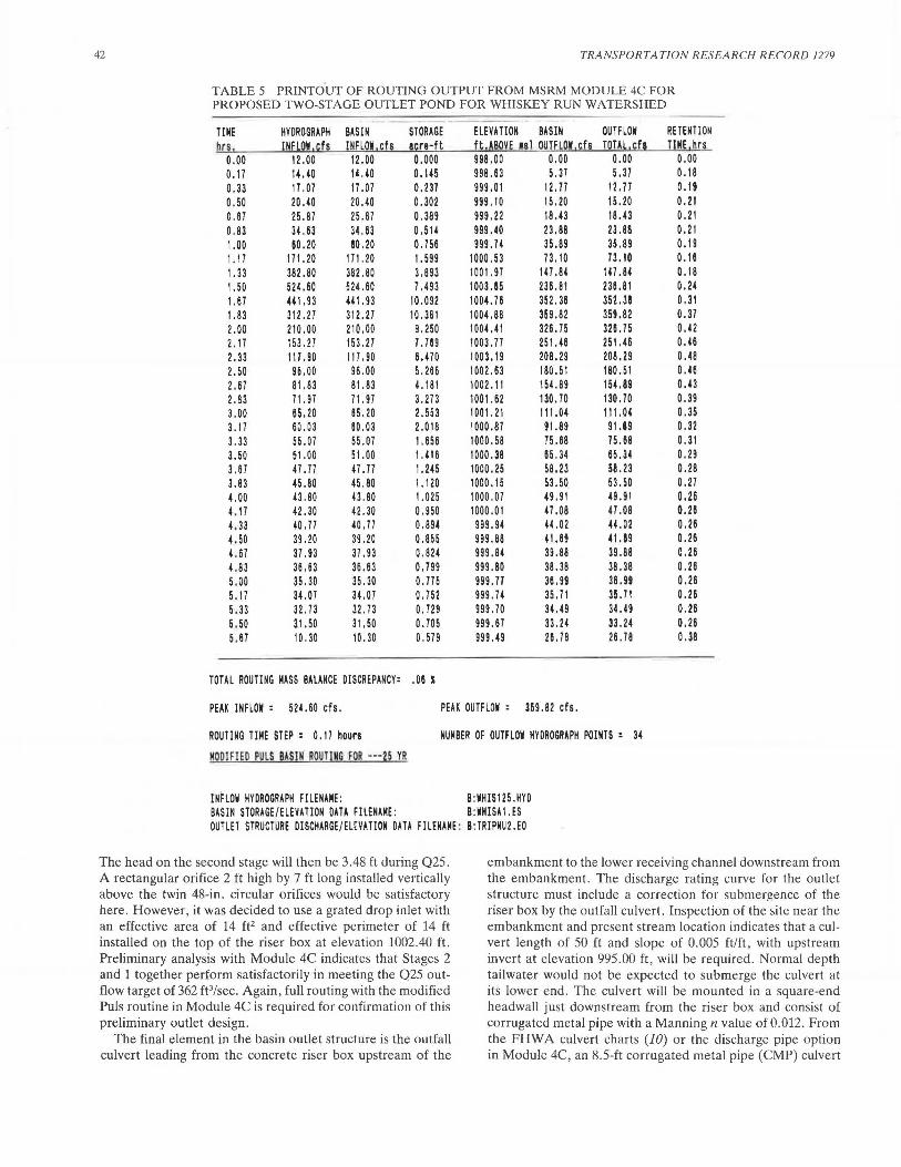
TABLE 5 PRINTG°UT OF ROUTING OUTPUT FROM MSRM MODULE 4C FOR PROPOSED TWO-STAGE OUTLET POND FOR WHISKEY RUN WATERSHED
---TIME HYDROGRAPH BASIN STORAGE ELEVATION BASIN OUTFLOW RETENT ION hrs, I NFLOW , ~fs INFL0~ 1 cfs a,re-ft ft, ~BOVE 111 OUTFLQW ,cfs TOTAl , ~fl TIME ,hr§
0 .00 12 .00 12 .00 0. 000 998.00 0. 00 0. 00 0 .oo 0 .17 14.40 14.40 0. 145 998. 63 5. 37 5. 37 0 .18 0. 33 17.07 17. 07 0. 237 999 .01 12. 77 12. 77 0. 19 0. 50 20 .40 20 .40 0. 302 999. 10 15. 20 15. 20 0. 21 0. 67 25. 87 25 .87 0. 389 999.22 18.43 18 .43 0. 21 0. 83 34.63 34.63 0.514 999. 40 23 .88 23. 88 0. 21 1.00 80. 20 80. 20 0. 756 999. 74 35 .89 35 .89 0 .19 1.17 171.20 171 . 20 1. 599 1000.53 73. 10 73 .10 0. 16 1.33 382. 80 382.80 3. 893 1001.97 147.84 1'7.84 0. 18 1.50 524. 60 524.60 7 .493 1003.85 236. 81 236. 81 0. 24 1.67 441.93 441. 93 10.092 1004. 76 352.38 352. 38 0. 31 1. 83 312. 27 312 .27 10. 381 1004.88 369 .82 359. 82 0. 37 2. 00 210 .00 210.00 9. 250 1004.41 326 . 75 326 . 75 0.42 2. 17 153. 27 153. 27 1.m 1003.77 251. 46 251 .46 0. 46 2. 33 117. 90 117. 90 6.m 1003.19 208.29 208. 29 0. 48 2. 50 96. 00 96 .00 5. 266 1002.63 180. 51 180. 51 0. 46 2. 67 81.83 81. 83 4. 181 1002 .11 154.89 154.89 G.43 2. 83 71. 97 71.97 3.273 1001.62 130 . 70 130. 70 0. 39 3 .00 65. 20 65. 20 2. 553 1001. 21 111.04 111. 04 0. 35 3 .17 60. 03 60.03 2.018 1000.87 91.89 91.89 0. 32 3. 33 55.07 55 .07 1. 656 1000.58 75. 88 75. 88 0. 31 3. 50 51.00 51.00 1.418 1000.38 65. 34 65.34 0. 29 3. 67 47.77 47.77 1.245 1000.25 58 .23 58. 23 0. 28 3 .83 45 .80 45. 80 1. 120 1000. 15 53. 50 53. 50 0. 27 uo 43. 80 43. 80 1. 025 1000 .07 49. 91 49. 91 0. 26 4. 17 42. 30 42. 30 0. 950 1000.01 47.08 47 .08 0. 26 4.33 40. 77 40. 77 0. 894 999.94 44.02 44.02 0. 26 4.50 39. 20 39. 20 0. 855 999.88 41.69 41.89 0. 26 4.67 37. 93 37. 93 0.824 999. 84 39. 88 39 .88 0. 26 4.83 36 . 63 36 . 63 0. 799 999. 80 38. 38 38. 38 0. 26 5 .00 35. 30 35.30 0. 775 999. 71 38. 99 36.99 0. 26 5. 17 34.07 34.07 0. 752 999. 74 35. 71 35. 71 0. 26 5' 33 32. 73 32. 73 0. 729 999. 70 34.49 34.49 0. 26 5. 50 31.50 31.SO 0. 705 999 .67 33. 24 33. 24 0. 26 5 .67 10. 30 10. 30 0. 579 999.49 26. 78 26 . 78 0. 38
TOTAL ROUTING MASS BALANCE DISCREPANCY: . 06 I
PEAK INFLOW : 524.60 cfs. PEAK OUTFLOW : 359.82 cfs.
ROUTING TIME STEP : o. 17 hours NUMBER OF OUTFLOW HYOROGRAPH POINTS : 34
MOO!FIEO PULS BAS IN ROUTING FOR ·--25 YR
INFLOW HYDROGRAPH FI LE NAME : B:WH!S125 .HYO BASIN STORAGE/ELEVATION om FILENAME : B:WHISA 1. ES OUTLET STRUCTURE OISCHARGE/EL~VATION om FILENAME : B:TRIPNU2.EO
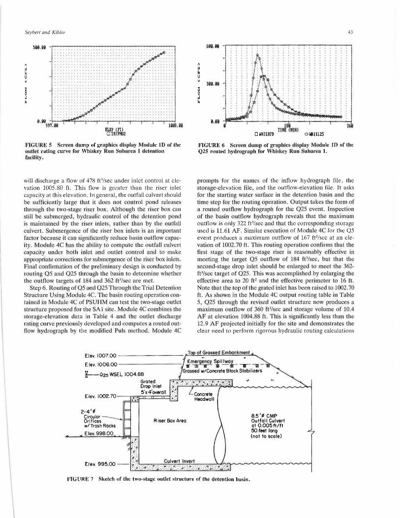
The head on the second stage will then be 3.48 ft during Q25. A rectangular orifice 2 ft high by 7 ft long installed vertically above the twin 48-in. circular orifices would be satisfactory here. However, it was decided to use a grated drop inlet with an effective area of 14 ft2 and effective perimeter of 14 ft installed on the top of the riser box at elevation 1002.40 ft. Preliminary analysis with Module 4C indicates that Stages 2 and 1 together perform satisfactorily in meeting the Q25 outflow target of 362 ft3/sec. Again , full routing with the modified Puls routine in Module 4C is required for confirmation of this preliminary outlet design.
The final element in the basin outlet structure is the outfall culvert leading from the concrete riser box upstream of the
embankment to the lower receiving channel downstream from the embankment. The discharge rating curve for the outlet structure must include a correction for submergence of the riser box by the outfall culvert. Inspection of the site near the embankment and present stream location indicates that a culvert length of 50 ft and slope of 0.005 ft/ft , with upstream invert at elevation 995.00 ft, will be required . Normal depth tailwater would not be expected to submerge the culvert at its lower end . The culvert will be mounted in a square-end headwall just downstream from the riser box and consist of corrugated metal pipe with a Manning n value of 0.012. From the FHWA culvert charts (10) or the discharge pipe option in Module 4C, an 8.5-ft corrugated metal pipe (CMP) culvert
Seybert and Kibler
Sllll.Sll - ••......••......•.•
"'" 0 0 o ••• + • ole ' ••I••' oO•• ••' ' ' • •• o• I. 0 •••et ....... ' ... ····· ......... ' ...... '. ······· t y•otooo 0 >101 Io 0000 I' - .................. ' ..
ELEU (FT) 0 TRIPHU2
FIGURE 5 Screen dump of graphics display Module ID of the outlet rating curve for Whiskey Run Su bar •a 1 detention facility.
will discharge a flow of 478 ft3/sec under inlet control at elevation 1005.80 ft. This flow is greater than the riser inlet capacity at this elevation. In general, the outfall culvert should be sufficiently large lhat it doe. not control pond releases through the two-stage ri er box. All'hough the riser b x C<rn sti ll be ubmerged hydraulic contr I of th detention pond i · maintained by the riser inlets , rath r than by th outfall culvert. ubmergen e f the riser box inlets i an important factor becaus · it can ignificantly reduce basin outflow capacity. Module 4 has th ability to compute the outfall culvert capacity under both inlel and oullet control and to make appropriate correction for ubmergence of the ri er box int t . Final co.nfirrnatio.n of the prelimiirnry design is conducted by routing QS and Q25 through the basin to determine whether the outflow targets of 184 and 362 (t3/sec are met.
tep 6. Routing of 05 and 025 Through the Trial Detention Structure Using Module 4C. The ba in routing operation contained in Module 4 of PSUHM can le t the two- tage outlet structure proposed for the Al site. M dule 4 c mbines the storage-eleva tion data in Table 4 and the outlet discharg rating CLu·ve previou. ly developed and computes a routed outflow hydrograp.h by the modified Pul method. Module 4
Elev. 1007.00 - - ------
Elev.1006.00 --------
43
m.ee -.----..----~-------------.
31lll.91l -
18 IIKE <KIHl
36
D WHISRID o NHIS125
FIGURE 6 Screen dump of graphics display Module ID of the Q25 routed hydrograph for Whiskey Run Subarea 1.
prompt for the names of the inflow hydr graph file, the storage-elevation file and the outflow-elevati n file. It asks for the starting water surface in the detention basin and the time tep for the r uting operation. Output take the form of a routed outfl w hydrograph for the Q25 event. Inspection of the basin outflow hydrograph reveal that the maximum outflow is only 322 ft3/sec and that the corresponding storage used is 11.61 AF. Similar execution of Module 4 for the Q5 event produces a maximum outflow of 167 ft3/sec at an elevation f 1002.70 ft. Thi r uting operation confirm that the fir l stage of the two- tage ri er i reasonably effective in meeting the target Q5 outflow f 184 ft3/ ec but that the econd-stage drop inlet should be enlarged to meet the 362-
ft3/ ·ec target of Q25. This was accomplished by enlarging the effective area to 20 ft2 and the effective perimcl r to 16 ft. Note that the top of the grated inlet has been raised to 1002. 70 ft. A hown in the Modul 4 output routing table in Table 5, Q25 through the revised outlet lructure now produce a maximum outflow of 360 ft3/sec and torag vo.lume of 10.4 AF at elevation 1004. ft. Thi i. i~nificantly le than the 12.9 AF proj cted initially for the ite and demon trates the clear need to perform rigorous hydraulic routing calculations
~· v
Emergency Spil lwoy • -m-.-- 111 - ar- --.- , -¥---025 WSEL 1004.88
Grossed wtConcrete Block Stabilizers
g~~~e~let ~:;.:·.~·;:~;:~ ' ::;·.~~,: ~ ;~ :.:,•;~~•'-~·':.;! ·. 5'x 4'overoll .:~ :·:
2-4'¢ Circular Orifices w/ Trash Rocks
Elev. 998.00
'>';'!:J:J::::::::n==n=t:.:.. Concrete 1:: .•:.: Headwall
Riser Box Area
FIGURE 7 Sketch of the two-stage outlet structure of the detention basin.
8.5 '¢ CMP Outfall Culvert at 0.005ft/ft 50feet long (not to scale)
44
for larger detention st:ruclures. Plot of the fin al outlet rating curve and the routed 025 byurt)gr. ph are ·hown in FigLrres 5 and 61 respectively . A ketch of the final outlet tructure is shown in Figure 7.
As a matter of interest Q25 wa routed through the final detention basin with the upper stage deleted from the outlet strncture. A expecte<.l ma imum outflow wns con~iderably reduced to 256 ft 3/sec versus the target 62 ft3/ ec. On the other hand , maximum torage require I wa increased to 13.7 AF at elevation 1006.22 fl. This example iJlustrates the difficulty of meetiug multiple outfl w targets with a single- ·t;:ig outflow structure. The final two-stage structure in this case does an excellent' job of meeting both the 05 and the 025 targets and probably provides considerable protection at other design frequencies as well.
REFERENCES
1. D. F. Kibler E. L. White, and T. A. eybert. Users A•l1111ual 10
111 Pe1111 tme Urba11 Hydrology Model . Penn ylvania State Univer ity, Department f Civil Engineering, May 1990.
2. Urban Hydrology for Small Wlllerslied -. Tech nical Release SS, U.S . Department of Agriculture, oil on ervation ervicc, June 1986.
3. Urban Hydrology for Small Watershed . Technical Release SS, U.S. Department of Asriculture, . oil .. nn~ervation Service. Jan. 197S.
TRANSPORTATION RESEARCH RECORD 1279
4. D. F. Kibler, ed. Urban tormwm •r llydrology. Water Resources Monograph 7, American Geophysical Union. Washington, D.C. , l982.
S. D. L. Yarnell. Rainfa/111111!11 'ii -Frequency Data. Miscellaneous Publication 204, .. Departmenl of griculture, Washing1on, D .. , 193S.
6. G. Aron, D. J. Wall, E. L. White, e1 al. Pennsylvania Deprlf/me111 of Tran porrat/011 Storm J111e11sity-D111·a1io11-Freq11e11cy 01ans (PDT- IDF') . ReportFHWA-PA-85-0J2.13nvironmcnt:il Resource Research lnstilt1te (lns1i1ute for Research on Land and Water Resources) .Penn ylvani;i tale University, University Park, Pu ., May 1986.
7. Hydrology. National Engineering Handbook Section 4, U.S. Department of Agricullu1c, Soil Con ·crvalion Sen•ice, Washington , D.C., 1972.
8. W. Viessman, J . W. Knapp, and G. L. Lewis. /11troduc1io11 10 Hydrology. 3rd ed., Harper and Row, New York , 1989.
9. A. S. hambcrla.in nr. A Multiple Swge De1e111/011 8(1si11 A11alysi mrtl n esig11 Modi.II. M.S. thesis, Dcpurtmcnt of Civil nginecring, Pennsylvania State University, University Park, Pa., Aug. 1986.
10. Hydraulic Desi}111 of Highway ulverts. Report FHWA-TP- 5-15. Hydraulic Design 'eries No. S. FHWA, U.:->. Uepanmcm of Transportation , ept. 19 S.
Publication of this paper sponsored by Committee on Hydrology, Hydraulics, and Water Quality.