pendulum hardness tester pendeldämpfungsprüfer · precision balances, therefore a vibration free...
TRANSCRIPT

Additives & InstrumentsA member of
Measure what you see.
Pendulum Hardness TesterPendeldämpfungsprüfer
Operating Instructions
Betriebsanleitung

Eng
lish
Deu
tsch
Pendulum Hardness Tester Pendeldämpfungsprüfer
Operating Instructions Bedienungsanleitung
Patent pendingPatent angemeldet
216 019 785 ED 07/10
BYK-Gardner GmbHLausitzer Str. 8D-82538 GeretsriedGermanyTel. 0-800-gardner (0-800-4273637) +49-8171-3493-0Fax +49-8171-3493-140
BYK - Gardner USA9104 Guilford RoadColumbia, MD 21046USAPhone 800-343-7721 301-483-6500Fax 800-394-8215 301-483-6555
www.byk.com/instruments/


3
Language directory / Sprachenverzeichnis
English ...........................................................................................................5
Deutsch .......................................................................................................25
Language directory / Sprachenverzeichnis

4
Dear customer,
thank you for having decided for a BYK-Gardner product. BYK-Gardner is committed to providing you with quality products and services. We offer complete system solutions to solve your problems in areas of color, appearance and physical properties. As the basis of our worldwide business, we strongly believe in total customer satisfaction. Therefore, in addition to our products, we offer many VALUE-ADDED services:
• Technical Sales Force
• Technical & Application Support
• Application and Technical Seminares
• Repair & Certifi cation Service
BYK-Gardner is part of Altana AG and a direct subsidiary of BYK-Chemie GmbH, a leading supplier of additives for coatings and plastics. Together, we offer complete and unique solutions for you, our customer.
Thank your for your trust and confi dence. If there is anything we can do better to serve your needs, do not hesitate to let us know.
Your BYK-Gardner Team
5
1. General and Safety Information ..............................................................7
2. System description ...............................................................................10
3. Installation .............................................................................................11
4. Mounting the Protective Casing ............................................................13
5 Operating and controls .........................................................................14
6. Adjust König method .............................................................................16
7. Adjust Persoz method ...........................................................................18
8. Test Procedure ......................................................................................19
9. Conversion Persoz/König ......................................................................20
10. Error lis ..................................................................................................21
11. Standards ..............................................................................................22
12. Technical Data .......................................................................................22
13. Delivery Content and Accessories ........................................................24
Eng
lish
Index

6
Reference note for this dokumentThie instruction manual is an important part of this instrument. It contains essential information about setting up, placing in service and use. If you pass the device on to another user, please ensure that the instruction manual is included with the instrument. The manual must be studied carefully before working with the equipment. Please contact your regional service offi ce if you have any questions or require additional information about the device.
The technology and fi ttings are based on state-of-the art optic and electronic technology. New developments and innovations are constantly being integrated into the equipment. Thus, the diagrams, dimensions, and technical data used in this manual may have changed as a result of adapting the device to new information and improvements.
© Copyright 2005 BYK-Gardner GmbHAll rights reserved
No portion of the software, documentation or other accompanying materials may be translated, modifi ed, reproduced, copied or otherwise duplicated (with the exception of a backup copy), or distributed to a third party, without prior written authorization from BYK-Gardner GmbH. In any cases, this requires the prior written consent of BYK-Gardner.
BYK-Gardner GmbH offers no guarantee that the software will function without error or that the functions incorporated therein can be executed on all applications and combinations selected by you.
No liability other than as provided by law as assumed for direct or indirect damage sustained in association with the use of the instrument, the software or documentation.
BYk-Gardner GmbH reserves the right to update the software and written documentation without prior notice.
Eng
lish
Reference note for this document
7
1. General and Safety Information
1.1. Symbols and terms
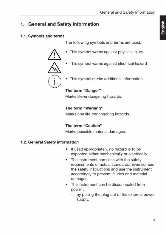
The following symbols and terms are used:
• This symbol warns against physical injury
• This symbol warns against electrical hazard
• This symbol marks additional information.
The term “Danger”Marks life-endangering hazards.
The term “Warning”Marks non life-endangering hazards.
The term “Caution”Marks possible material damages.
1.2. General Safety information
• If used appropriately, no hazard is to be expected either mechanically or electrically.
• The instrument complies with the safety requirements of actual standards. Even so read the safety instructions and use the instrument accordingly to prevent injuries and material damages.
• The instrument can be disconnected from power :- by pulling the plug out of the external power
supply.
Eng
lish
General and Safety Information

8
- by disconnecting the DC plug from the external power supply to the instrumentMake sure that the power plug is always easy to access!
• Any damage or injury caused by ignoring the safety instructions, general information or improper usage, no warranty or product liability from the manufacturer can be claimed.
• Keep this manual for reference always near by the instrument.
• In case of transferring this instrument, make sure this manuaI is included.
I DangerBefore starting, read the manual and follow the safety instructions and general information. Unpack the instrument and check the delivery contents for completeness (Please refer to chapter “Delivery Contents”).
If safe usage of the instrument is obviously impossible, immediately put the instrument out of action and prevent it from unintentional activation. Safe usage is impossible:
- if the instrument is visibly damaged
- or does not work anymore
- after long-storage under bad conditions
- after heavy transport stress
Do not perform any electrical or mechanical repair. The instrument may only be opened by a trained service technician. Please contact our technical service for assistance.
Only devices conforming to the safety standards for low voltage appliances are allowed to be connected to the DC input.
Use only the power supply and connection cable delivered with the instrument.
Eng
lish
General and Safety Information
9
Use the original accessories available for the instrument, additional information can be found in the chapters: technical data, standards, and delivery content.
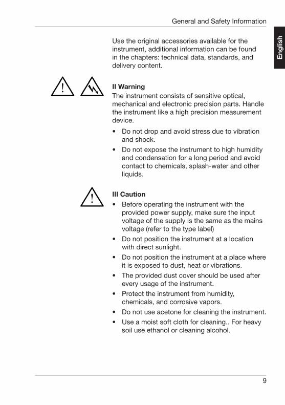
II WarningThe instrument consists of sensitive optical, mechanical and electronic precision parts. Handle the instrument like a high precision measurement device.
• Do not drop and avoid stress due to vibration and shock.
• Do not expose the instrument to high humidity and condensation for a long period and avoid contact to chemicals, splash-water and other liquids.
III Caution• Before operating the instrument with the
provided power supply, make sure the input voltage of the supply is the same as the mains voltage (refer to the type label)
• Do not position the instrument at a location with direct sunlight.
• Do not position the instrument at a place where it is exposed to dust, heat or vibrations.
• The provided dust cover should be used after every usage of the instrument.
• Protect the instrument from humidity, chemicals, and corrosive vapors.
• Do not use acetone for cleaning the instrument.
• Use a moist soft cloth for cleaning.. For heavy soil use ethanol or cleaning alcohol.
Eng
lish
General and Safety Information

10
2.1 Delivery content
PH-5858 Pendulum tester König
PH-5856 Pendulum König
PH-5860 wire release
Protective cover acrylic glass
Power supply
Manual
AlternativePH-5859 Pendulum tester Persoz
PH-5857 Pendulum Persoz
PH-5860 wire release
Protective cover acrylic glass
Power supply
Manual
Accessories and spare partsPH-5856 Pendulum König
PH-5857 Pendulum Persoz
PH-5860 wire release
2. System descriptionThe pendulum hardness tester is an instrument to determine the elastic hardness of coatings according to DIN EN ISO 1522 and ASTM D 4366. It consists of a sample holder where a pendulum freely oscillates on the sample surface and a counting device. The number of oscillations in a defi ned angular range is a measure for the elastic hardness of a coating. It is expressed in seconds or number of oscillations.
The number of oscillations is detected by light barriers in the lower part of the instrument and is shown on the display as seconds or oscillations.
System description
Eng
lish

11
3. Setting up the instrument
• Unpack the instrument and check for possible transport damage.
• Before starting make sure delivery is complete.The pendulum tester is delivered calibrated and ready for use. Only the protective cover needs to be mounted after delivery.
Pendulum hardness testers are as sensitive as precision balances, therefore a vibration free position on a special table suitable for balances is recommended.
After installing the instrument on a suitable location, remove the protective cover.
• Plug in the power supply and switch on the instrument.
• Balance the instrument properly by turning the screw feet according to the bubble level on top and lock it with the counter nuts (open-ended wrench size 10)
• For testing according to Koenig, mount the wire release at 6° mark of the scale, for Persoz at 12 °.
• Clean the balls of the pendulum and the adjustable glass plate with alcohol.
• Place the glass plate on the lifting table.
• Raise the lifting table to the stop.
• Turn the handle by 180° to the stop position. The handle sits horizontally and points forward.
• If the bubble level is exactly horizontal, the glass plate is also in a straight position.
• Lower the lifting table by turning the handle.
• Place the pendulum exactly with the small holes on the pins of the lifting table, the marking arrow on the bar of the pendulum must point to the front. If it is placed the wrong way, the light barriers and the counter are inoperable.
Setting up the instrument
Eng
lish

12
• Slowly raise the lifting table with the glass plate up to the pins . The handle is in horizontal position and points forward. The pendulum must lift up equally with both balls, if not the pins can be moved slightly in vertical direction. In the lifted position the pendulum must swing freely.
• Check the position of scale to the pendulum. The completely stopped pendulum must point exactly to the zero marking of the scale. If not, check the tip of the pendulum. If twisted, straighten it and position the pendulum with the lifting table in the lowered position and then raise it. Repeat this procedure three times to assure an equal rest.
• Pull out the handle.
• Put the protective cover (mounting see chapter 9) onto the instrument. The case fi ts exactly onto the edges of the base plate. Eventually fi x the cover plates in the treads with a suitable adhesive.
• Insert the handle through the opening in the cover into the jack underneath the lifting table. Check the bubble level once more, correct the leveling if necessary.
The pendulum tester is now ready for operation.
Setting up the instrument
Eng
lish

13
Mounting of the protective cover
4. Mounting of the protective coverRemove the protective fi lm and clean the acrylic glass parts. Attach the profi le rail (8) with miter on top sidewise to part (1) and (2). Push Parts (3) and (4) from above into the profi le rails, shift the profi le (9) onto part (5). Attach Part (5) to part (1) and part (2). Mount Knob (10) on part (6) and (7). Shift part (6) and (7) from above (with knob outside). The acrylic glass parts can be fi xed to the profi le rails with an appropriate adhesive.
Eng
lish

14
Control elements and operation
5. Control elements and operation
5.1. Control elements
Four buttons to control the instrument sit on the front panel
start/stop
signal
modus
enter
To prepare a measurement fi rst choose the appropriate method by pressing the ”mode“ button: four settings are available:
• Persoz 4° time
• Koenig 3° osc.
• No Std. 4° osc.
• No Std. 3° time
According to the standards for
• Persoz: oscillation time in seconds
• König: number of oscillations
The combinations
• 4° amplitude / number of oscillations and3° amplitude / oscillation time are not defi ned in the standards.
• The selected method is confi rmed by pressing the ”enter”-button.
• Move the pendulum with the displacement arm to the starting position.
• Press the wire release to hold the pendulum in position
• Press “Start/Stop“- button, an asterisk appears on the display and the red LED lights up(no air draft or vibration from now on)
Eng
lish

15
Control elements and operation
• Release the pendulum, the measurement starts
• At the end of the measurement, the asterisk disappears and the green LED lights up
The measurement result appears on the display and an optional signal sounds
Setup the acoustic signal sound(Setup not possible if ”Start/Stop“ function is active - red LED)
Press the “signal” button
Five settings are available:
• 5 s
• 15 s
• 60 s
• infi nite ∞
• off ---Confi rm with “enter”
Eng
lish
16
Adjustment for König
6. Adjustment for König
6.1. Standards
ASTM D 4366
DIN EN ISO 1522
Pendulum and light barrier are adjusted at delivery. A periodical recertifi cation by authorized service personal is recommended for equipment monitoring.
6.2. Duration of pendulum oscillation
According to the Standard one pendulum oscillation is specifi ed with 1.4 s ± 0.02 s. This value can be verifi ed by the following procedure:
• Mount the wire release at 6 °
• Raise the lifting table to the stop and check the zero position.
• Move the pendulum to 6 ° position and fi x it with the wire release. Press start button.
• Release pendulum
• Repeat the procedure with the 3° osc. mode. . After 100 oscillations the elapsed time must be 140 + 2s. If not, please call a service technician for adjusting.
6.3. Damping time
The damping time is the change of oscillations from 6° to 3°.The damping time from 6° to 3° must be 250 ± 10s on the glass plate (for tolerance please check actual version of the standards.)´This can be verifi ed with the following procedure:
• Level the instrument with the positioning feet exactly horizontally control of the bubble level.
• Move the pendulum to 6° position and hold it with the wire release.
Eng
lish
17
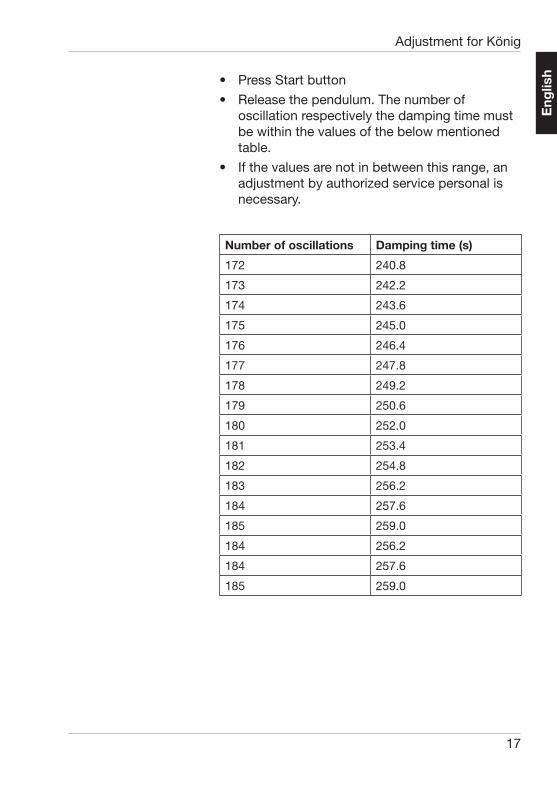
Number of oscillations Damping time (s)
172 240.8
173 242.2
174 243.6
175 245.0
176 246.4
177 247.8
178 249.2
179 250.6
180 252.0
181 253.4
182 254.8
183 256.2
184 257.6
185 259.0
184 256.2
184 257.6
185 259.0
Adjustment for König
• Press Start button
• Release the pendulum. The number of oscillation respectively the damping time must be within the values of the below mentioned table.
• If the values are not in between this range, an adjustment by authorized service personal is necessary.
Eng
lish
18
Adjustment according to Persoz
7. Adjustment according to Persoz
7.1. Standards
ASTM D 4366, DIN EN ISO 1522
7.2. Duration of oscillation
According to the Standards the time of one oscillation is one second at 12°.
7.3. Damping time
The damping time from 12° to 4° must be 430 ± 10 seconds on the glass plate.
This value can be controlled with the procedure described in chapter 3.
Eng
lish

19
Testing procedure
8 Testing procedure
• Mount the wire release at 12°
• Choose the appropriate method with the mode button.
• Choose the required signal options
• Place the sample on the lifting table.
• Raise the table to the stop.
• Move the pendulum to the 12 ° position and hold it with the wire release.
• Start Measurement. By pressing the start button.
• Release the pendulum with the wire release.The signal starts at the end of measurement and the result is shown on the display.
Eng
lish
20
Exchange König/Persoz
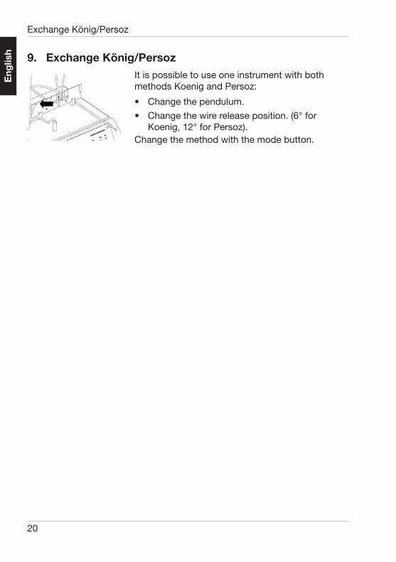
9. Exchange König/PersozIt is possible to use one instrument with both methods Koenig and Persoz:
• Change the pendulum.
• Change the wire release position. (6° for Koenig, 12° for Persoz).
Change the method with the mode button.
Eng
lish

21
10. Error list
Counter does not work properly
Pendulum not attached properly
Attach pendulum with arrow to the front
Tip of pendulum is dirty Clean the polished tip of the pendulum.
No display Power supply not plugged in properly
Check power connec-tion
Error list
Eng
lish

22
11. StandardsASTM D 4366
DIN EN ISO 1522
Standards / Technical Data
12. Technical Data
12.1 Instrument
Input: 12 V DC; 0.12 A
Size: LxWxH=(320x300x710) mm
Weight: 17.5 kg
12.2 External Power supply
Input: 100-240 VAC; 50/60 Hz; 800 mA
Output: 12 VDC, 2.5 A
Size: LxWxH=(95x45x30) mm
Weight: 0.32 kg
12.3 General
Temperature range: 10-40 °C (Use)
0-60 °C (Storage)
Rel. humidity: up to 85% at 35 ° C non- condensing.
Eng
lish

23
13. Delivery contentPH-5858 Pendulum tester König
PH-5856 Pendulum König
PH-5860 wire release
Protective cover acrylic glass
Power supply
Manual
Alternative
PH-5859 Pendulum tester Persoz
PH-5857 Pendulum Persoz
PH-5860 wire release
Protective cover acrylic glass
Power supply
Manual
Accessories and spare parts
PH-5856 Pendulum König
PH-5857 Pendulum Persoz
PH-5860 wire release
Delivery content and Accessories
Eng
lish

24
Eng
lish

25
Deu
tsch
Inhaltsverzeichnis
1. Allgemeine- und Sicherheitshinweise .................................................. 27
2. Systembeschreibung ........................................................................... 31
3. Aufstellen des Gerätes ......................................................................... 32
4. Montage der Schutzhaube ................................................................... 35
5. Bedienungselemente und Bedienung .................................................. 36
6. Justierung nach König ......................................................................... 38
7. Justierung nach Persoz ........................................................................ 40
8. Durchführung der Prüfung .................................................................... 41
9. Umrüstung Persoz/König ..................................................................... 42
10. Fehlersuchliste ..................................................................................... 43
11. Normen ................................................................................................. 44
12. Technische Daten ................................................................................. 44
13. Lieferumfang und Zubehör ................................................................... 45

26
Deu
tsch
Hinweise zu diesem DokumentDiese Betriebsanleitung ist Bestandteil des Geräts mit dem sie geliefert wurde. Sie enthält wichtige Hinweise zur Aufstellung, Inbetriebnahme und Handhabung. Achten Sie bei der Weitergabe des Gerätes darauf, dass die Betriebsanleitung dem Gerät beigefügt ist. Sie ist vor Beginn der Arbeit auf-merksam zu lesen. Sollten Sie zusätzliche Fragen haben oder Informationen wünschen, wenden Sie sich bitte an die zuständige regionale Servicestelle.
Technik und Ausstattung entsprechen dem neuesten Stand optischer und elektronischer Technik. Weiterentwicklungen und Verbesserungen werden laufend berücksichtigt. Daher können sich die Abbildungen, Maße oder technischen Daten in dieser Betriebsanleitung in der Zwischenzeit durch Anpassung an neue Erkenntnisse und Verbesserungen verändert haben.
© Copyright 2005 BYK-Gardner GmbHAlle Rechte vorbehalten
Kein Teil der Software, der Dokumentation oder sonstigen Begleitmaterials darf übersetzt, abgeändert, reproduziert, kopiert oder anders vervielfältigt, mit Ausnahme einer Sicherheitskopie, oder Dritten zugänglich gemacht wer-den. Hierzu ist in jedem Fall die vorherige schriftliche Zustimmung von BYK-Gardner einzuholen.
BYK-Gardner übernimmt keine Gewähr dafür, dass die Software fehlerfrei arbeitet und, dass die in ihr enthaltenen Funktionen in allen ihrerseits ge-wählten Anwendungen und Kombinationen ausführbar sind.
Eine Haftung für mittelbare oder unmittelbare Schäden, die in Zusammen-hang mit dem Gebrauch des Messgeräts, der Software oder Dokumentation entstehen, ist ausgeschlossen, soweit es gesetzlich zulässig ist.
BYK-Gardner behält sich vor, Aktualisierungen der Software und des schrift-lichen Materials ohne vorherige Ankündigungen vorzunehmen.

27
Deu
tsch
Allgemeine- und Sicherheitshinweise
1. Allgemeine- und Sicherheitshinweise
1.1. Symbole und Begriffe
Die folgenden Symbole und Begriffe fi nden Ver-wendung:
• Dieses Symbol warnt vor Verletzungsgefahren
• Dieses Symbol warnt vor Gefahren durch elektrische Energie
• Dieses Symbol kennzeichnet weitere Hinweise
Der Begriff „Gefahr“Weißt auf lebensbedrohliche Verletzungsgefahren hin.
Der Begriff „Warnung“Weißt auf nicht lebensbedrohliche Verletzungsge-fahren hin.
Der Begriff „Hinweis“Weißt auf mögliche Geräte bzw. Materialschäden hin.
1.2. Allgemeine Sicherheitshinweise
• Bei sachgemäßer Verwendung des Gerätes sind keine Gefahren zu befürchten, weder durch mechanische noch durch elektrische Einwirkung.
• Das Gerät entspricht allen Sicherheitsanforder-ungen geltender Regelwerke. Lesen Sie trotz-dem die Sicherheitshinweise und verwenden Sie das Gerät nur in der beschriebenen Weise
28
Deu
tsch
um Gesundheitsschäden und Gerätedefekte zu verhindern.
• Das Gerät kann folgendermaßen von der Stromversorgung getrennt werden:- durch Ziehen des Netzsteckers der
Netzanschlussleitung des externen Tischnetzteils.
- durch Ziehen des DC-Eingangssteckers vom externen Netzteils zum Gerät
Stellen Sie sicher, dass der Netzstecker immer leicht zugänglich ist!
• Im Falle einer nicht sachgemäßen Verwen-dung oder Nichtbeachtung der Hinweise in der Bedienungsanleitung oder am Gerät können weder Garantie- noch Produkt-haftungsansprüche geltend gemacht werden.
• Bewahren Sie diese Bedienungsanleitung zur späteren Referenz immer in der Nähe des Gerätes auf.
• Im Falle der Weitergabe des Gerätes stellen Sie sicher, dass diese Bedienungsanleitung mitgeliefert wird.
I GefahrVor Einschalten und Inbetriebnahme des Gerätes lesen Sie zuerst die Bedienungsanleitung und be-achten Sie die Sicherheitshinweise
Wenn anzunehmen ist, dass ein gefahrloser Be-trieb nicht mehr möglich ist, so ist das Gerät au-ßer Betrieb zu setzen und gegen unabsichtlichen Betrieb zu sichern. es ist anzunehmen, dass ein gefahrloser Betrieb nicht mehr möglich ist,
– wenn das Gerät sichtbare Beschädigungen aufweist
– wenn das Gerät nicht mehr funktioniert
– nach längerer Lagerung unter ungünstigen Verhältnissen
Allgemeine- und Sicherheitshinweise

29
Deu
tsch
– nach schweren Transportbeanspruchungen
Führen Sie keine Reparaturen am Gerät durch, weder mechanische noch elektrischer Art. Dieses Gerät darf nur von geschultem Servicepersonal geöffnet werden. Bitte kontaktieren Sie für Repara-turen unseren Technischen Service, dort hilft man Ihnen gern so schnell wie möglich.
Am DC-Eingang dürfen nur Geräte angeschlos-sen werden die die Anforderungen für Sicherheits-kleinspannung erfüllen.
Benutzen Sie ausschließlich das mitgelieferte Netzteil und Netzanschlusskabel.
- Verwenden Sie nur geeignetes Zubehör und Er-satzteile die für das Gerät erhältlich sind, weitere Informationen fi nden Sie in den Kapiteln: Techni-sche Daten, Standards und Lieferumfang.
Benutzen Sie ausschließlich das mitgelieferte Netzteil und Netzanschlusskabel.
II WarnungDas Gerät besteht aus empfi ndlichen elektroni-schen und mechanischen Teilen, behandeln Sie das Gerät wie ein Präzisionsmessgerät,
• verhindern Sie Stöße und Vibrationen
• Setzen Sie das Gerät nicht für längere Zeit erhöhter Luftfeuchtigkeit und Kondensation aus. Verhindern Sie den Kontakt mit Chemikalien, Spritzwasser und andern Flüssigkeiten.
Allgemeine- und Sicherheitshinweise

30
Deu
tsch
III Achtung
• Beim Betrieb mit dem externen Netzteil ist darauf zu achten, dass die Nennspannung des Netzteils (siehe Typenschild des Netzteils) mit der Netzspannung Ihrer Netzsteckdose übereinstimmt.
• Stellen Sie das Gerät an einem Ort ohne direkte Sonneneinstrahlung auf
• Stellen Sie das Gerät nicht an einem Ort auf an dem es Staub, Hitze oder starken Vibrationen ausgesetzt ist.
• Schützen Sie das Gerät vor Feuchtigkeit, Chemikalien und korrosiven Dämpfen.
• Verwenden Sie kein Aceton zur Reinigung des Gerätes
• Zur Reinigung verwenden Sie einen weichen feuchten Lappen, bei starker Verschmutzung verwenden Sie Ethanol oder Reinigungsalkohol.
Allgemeine- und Sicherheitshinweise

31
Deu
tsch
2. SystembeschreibungDer Pendeldämpfungs-Prüfer ist ein Gerät zur Prüfung der elastischen Härte von Beschichtungen nach DIN EN ISO 1522. Es besteht aus einem Probentisch auf dem ein Pendel frei auf der Pro-benoberfl äche schwingen kann und einem Zähl-werk. Die Anzahl der Schwingungen in einem defi nierten Winkelbereich ist Maß für die elastische Härte einer Beschichtung und wird in Sekunden oder Schwingungsanzahl angegeben.
Die Schwingungsanzahl wird durch Lichtschran-ken im unteren Teil des Pendelprüfers bestimmt und auf einem Display als Sekunden oder Schwin-gungswert ausgegeben.
Systembeschreibung
2.1 Lieferumfang
PH-5858 Pendelprüfer nach König
PH-5856 Pendel nach König
PH-5860 Drahtauslöser
Schutzhaube aus Acrylglas
Netzteil
Bedienungsanleitung
oderPH-5859 Pendelprüfer nach Persoz
PH-5857 Pendel nach Persoz
PH-5860 Drahtauslöser
Schutzhaube aus Acrylglas
Netzteil
Bedienungsanleitung
Zubehör und Ersatzteile:PH-5856 Pendel nach König
PH-5857 Pendel nach Persoz
PH-5860 Drahtauslöser

32
Deu
tsch
3. Aufstellen des Gerätes
a. Gerät auspacken und auf eventuelle Transportschäden kontrollieren
b. Vor Inbetriebnahme die Lieferung auf Vollständigkeit überprüfen
Der Pendeldämpfungs-Prüfer wird fertig justiert und aufstellbereit geliefert. Lediglich die Schutz-haube ist nach Erhalt der Sendung noch zusam-menzubauen
Pendeldämpfungsprüfer sind ebenso empfi ndliche Geräte wie Analysenwaagen. Deshalb wird die er-schütterungsfrei Aufstellung auf einem Wägetisch empfohlen.
Nach Aufstellen des Grundgerätes am vorgesehe-nen Standort wird die Schutzhaube vorerst nicht aufgesetzt.
• Das Netzgerät einstecken und Gerät einschalten
• Das Gerät durch Verstellen der Nivellierfüße nach der Dosenlibelle exakt horizontal ausrichten und mit Kontermutter (10er Gabelschlüssel) fi xieren.
• Für die Prüfung nach König, den Drahtauslöser an der 6° Markierung der Skala einschrauben, für die Prüfung nach Persoz an der 12° Markierung.
• Die Kugeln des Pendels und die Justier-glasplatte mit Aceton oder Alkohol reinigen.
• Die Justierplatte aus Glas auf den Hebetisch legen.
• Hebetisch mit der Justierglasplatte bis zum Anschlagstift anheben.
• Den Bedienungshebel um 180° bis zum Endanschlag drehen. Der Hebel steht dann waagerecht und weist nach vorn.
Aufstellen des Gerätes

33
Deu
tsch
• Mit der exakten horizontalen Ausrichtung der Dosenlibelle ist die genaue horizontale Lage der Justierglasplatte durch die Werkseinstellung gewährleistet.
• Den Hebetisch absenken.
• Das Pendel so in die Kegelzapfen des Hebe-tischhalters einsetzen, dass der Markierungs-pfeil auf dem Trägerbalken nach vorne zur Frontseite des Gerätes zeigt. Bei falscher Einhängung des Pendels sind die Lichtschranke und das Zählwerk funktionslos.
• Den Hebetisch mit aufgelegter Justierglasplatte langsam bis zu den Anschlagstiften anheben. Der Hebel steht waagerecht und weist nach vorn. Dabei muss das Pendel mit beiden Kugeln gleichmäßig abheben. Falls das nicht der Fall ist, die Lage der verstellbaren Kegelzapfen durch Verschieben in vertikaler Richtung verändern.
Das Pendel muss im angehobenen Zustand frei schwingen.
• Die Stellung der Skala zum Pendel überprüfen. Das völlig zur Ruhe gekommene Pendel muss über der Nullmarkierung der Skala stehen. Wenn das nicht der Fall ist, zunächst die Pendelspitze überprüfen. Falls sie verbogen ist, wird sie gerichtet und das Pendel bei abgesenktem Hebetisch wieder eingehängt und ausgehoben. Zur Gewährleistung einer gleichmäßigen Aufl age wird dieser Vorgang dreimal wiederholt.
• Den Bedienungshebel des Hebetischs abziehen.
• Die gemäß Kapitel 8 wie in Abb. 3 montierte Haube so auf das Gerät setzen, dass die Grundplatte des Stativs exakt von den Innenkanten der Haube umgeben ist. Eventuell Acrylglasscheiben in den Profi len mit Kleber fi xieren.
Aufstellen des Gerätes

34
Deu
tsch
• Den Bedienungshebel durch die Bohrung der Plexiglaswand stecken und wieder in die geschlitzte Buchse unterhalb des Hebetisches einstecken. Dosenlibelle noch einmal überprüfen, ggf. korrigieren
Damit ist der Pendeldämpfungs-Prüfer betriebs-bereit.
Aufstellen des Gerätes
35
Deu
tsch
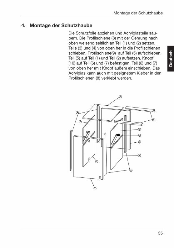
4. Montage der SchutzhaubeDie Schutzfolie abziehen und Acrylglasteile säu-bern. Die Profi lschiene (8) mit der Gehrung nach oben weisend seitlich an Teil (1) und (2) setzen. Teile (3) und (4) von oben her in die Profi lschienen schieben, Profi lschiene(9) auf Teil (5) aufschieben. Teil (5) auf Teil (1) und Teil (2) aufsetzen. Knopf (10) auf Teil (6) und (7) befestigen. Teil (6) und (7) von oben her (mit Knopf außen) einschieben. Das Acrylglas kann auch mit geeignetem Kleber in den Profi lschienen (8) verklebt werden.
Montage der Schutzhaube
36
Deu
tsch
5. Bedienungselemente und Bedienung
5.1. Bedienungselemente
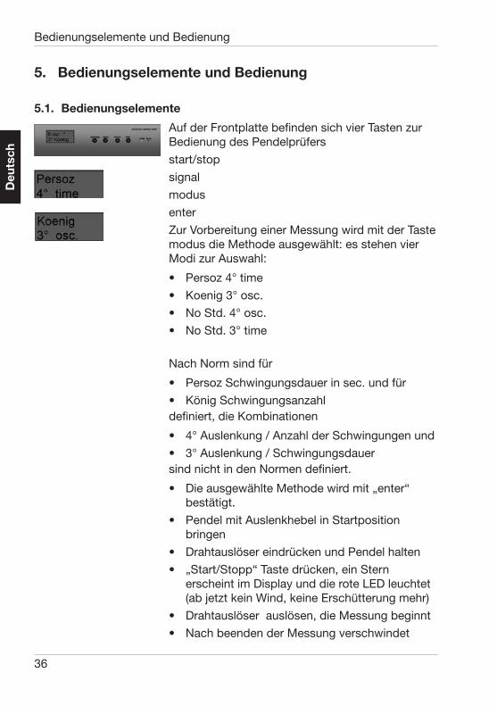
Auf der Frontplatte befi nden sich vier Tasten zur Bedienung des Pendelprüfers
start/stop
signal
modus
enter
Zur Vorbereitung einer Messung wird mit der Taste modus die Methode ausgewählt: es stehen vier Modi zur Auswahl:
• Persoz 4° time
• Koenig 3° osc.
• No Std. 4° osc.
• No Std. 3° time
Nach Norm sind für
• Persoz Schwingungsdauer in sec. und für
• König Schwingungsanzahl defi niert, die Kombinationen
• 4° Auslenkung / Anzahl der Schwingungen und
• 3° Auslenkung / Schwingungsdauer sind nicht in den Normen defi niert.
• Die ausgewählte Methode wird mit „enter“ bestätigt.
• Pendel mit Auslenkhebel in Startposition bringen
• Drahtauslöser eindrücken und Pendel halten
• „Start/Stopp“ Taste drücken, ein Stern erscheint im Display und die rote LED leuchtet (ab jetzt kein Wind, keine Erschütterung mehr)
• Drahtauslöser auslösen, die Messung beginnt
• Nach beenden der Messung verschwindet
Bedienungselemente und Bedienung

37
Deu
tsch
der Stern aus der Anzeige und die grüne LED leuchtet
Der Messwert erscheint auf dem Display und auf Wunsch ertönt ein Signal.
Einstellen des Signaltons:(Einstellung nur möglich, wenn „Start/Stopp“ nicht aktiv ist)
Taste Signal drücken
fünf Einstellungen für die Signaldauer sind mög-lich:
• 5 s
• 15 s
• 60 s
• unendlich ∞
• aus ---Nach Auswahl mit der enter Taste bestätigen
Bedienungselemente und Bedienung

38
Deu
tsch
6. Justierung nach König
6.1. Normen
ASTM D 4366
DIN EN ISO 1522
Pendel und Lichtschranke sind bereits werkseitig justiert. Eine regelmäßige Kontrolle der Justage durch autorisiertes Servicepersonal wird im Rah-men der Prüfmittelüberwachung empfohlen.
6.2. Dauer der Pendelschwingung
Nach Norm ist die Dauer einer Pendelschwingung mit 1,4 s ± 0.02 s angegeben. Dieser Wert wird wie folgt überprüft:
• Drahtauslöser bei 6° einschrauben
• Den Hebetisch bis zum Anschlag anheben und die Nullstellung überprüfen.
• Das Pendel auf 6° auslenken und arretieren. Start taste drücken.
• Pendel auslösen
• Wiederholen mit König osc. und sec durch osc teilen, Wert muss zwischen 1,38 und 1,42 liegen. wenn nicht Justage durch Servicetechniker notwendig.
6.3. Dämpfungsdauer
Die Dämpfungsdauer von 6° auf 3° soll auf der Justierglasplatte 250 ± 10s betragen (Toleranzbe-reich siehe aktuelle Version der Norm) Das kann wie folgt überprüft werden:
• Das Gerät durch Verstellen der Nivellierfüße nach der Dosenlibelle exakt horizontal ausrichten.
• Das Pendel auf 6° auslenken und arretieren
• Start drücken
Justierung nach König

39
Deu
tsch
• Das Pendel durch den Drahtauslöser freigeben die Zahl der Schwingungen, bzw. die Dämpfungsdauer muss entsprechend der nachstehenden Tabelle erreicht werden.
• Falls die Erreichte Zahl nicht im Bereich der Tabelle liegt ist eine Justage durch Servicepersonal erforderlich.
Justierung nach König
Anzahl der Schwingungen
Dämpfungsdauer (s)
172 240.8
173 242.2
174 243.6
175 245.0
176 246.4
177 247.8
178 249.2
179 250.6
180 252.0
181 253.4
182 254.8
183 256.2
184 257.6
185 259.0
184 256.2
184 257.6
185 259.0

40
Deu
tsch
7. Justierung nach Persoz
7.1. Normen
ASTM D 4366, DIN EN ISO 1522
7.2. Dauer der Pendelschwingung
Nach Norm ist die Dauer einer Pendelschwingung mit 1,0 Sekunden angegeben.
7.3. Dämpfungsdauer
Die Dämpfungsdauer von 12° auf 4° (Lichtschranke) soll auf der Justierglasplatte 430 ± 10 Sekunden betragen.
Die Kontrolle dieser Werte erfolgt wie in Kapitel 3 beschrieben.
Justierung nach Persoz

41
Deu
tsch
Durchführung der Prüfung
8. Durchführung der Prüfung
• Drahtauslöser bei 12° einschrauben
• Mit der „mode“-Taste die dem Pendel entsprechende Meßmethode nach Persoz einstellen, Abb. 1 (8).
• Die gewünschte Signaltondauer einstellen (6).
• Die Probe auf den Hebetisch legen.
• Den Hebetisch bis zum Anschlag anheben.
• Das Pendel auf 12° auslenken und arretieren.
• Die Messung starten (5).
• Das Pendel durch den Drahtauslöser (4) freigeben.
Der Signalton ertönt bei Messende und der Mess-wert wird im Display angezeigt.

42
Deu
tsch
9. Umrüstung Persoz/KönigEs ist möglich, die beiden Meßmethoden nach König und Persoz mit nur einem Grundgerät durchzuführen:
• Das Pendel auswechseln (siehe auch Kap. 2)
• Den Drahtauslöser an der entsprechenden Markierung (6° für Prüfung nach König oder 12° bei Prüfung nach Persoz) einsetzen, Abb. 1 (9, 10).
Mit der „mode“-Taste auf die geänderte Methode umstellen.
Umrüstung Persoz/König

43
Deu
tsch
10. Fehlersuchliste
Zählwerk arbeitet nicht einwandfrei
Pendel nicht richtig eingehängt
Pendel mit Markie-rungsteil nach vorne eingehängt
Pendelspitze verschmutzt
polierte Seite der Pendelspitze reinigen
Keine Anzeige Netzteil nicht richtig eingesteckt
Verbindung Netzteil mit Netzanschluss überprüfen
Fehlersuchliste
44
Deu
tsch 12. Technische Daten
12.1 Messgerät
Eingang: 12 V DC; 0,12 A
Maße: LxBxH=(320x300x710) mm
Gewicht: 17,5 kg
12.2 Externes Netzteil
Eingang: 100-240 VAC; 50/60 Hz; 800 mA
Ausgang: 12 VDC, 2,5 A
Abmessungen: LxBxH=(95x45x30) mm
Gewicht: 0,32 kg
12.3 Allgemein
Temperaturbereich: 10-40 °C (Gebrauch)
0-60 °C (Lagerung)
Rel. Luftfeuchte: bis zu 85% bei 35 °C nicht kondensierend.
Normen / Technische Daten
11. NormenASTM D 4366
DIN EN ISO 1522

45
Deu
tsch
Lieferumfang und Zubehör
13. LieferumfangPH-5858 Pendelprüfer nach König
PH-5856 Pendel nach König
PH-5860 Drahtauslöser
Schutzhaube aus Acrylglas
Netzteil
Bedienungsanleitung
oder
PH-5859 Pendelprüfer nach Persoz
PH-5857 Pendel nach Persoz
PH-5860 Drahtauslöser
Schutzhaube aus Acrylglas
Netzteil
Bedienungsanleitung
Zubehör und Ersatzteile:
PH-5856 Pendel nach König
PH-5857 Pendel nach Persoz
PH-5860 Drahtauslöser

46
Deu
tsch
EC - declaration of conformity / EG - Konfromitätserklärung
EC declaration of conformity / EG - Konformitätserklärung
We / Wir BYK-Gardner GmbH Lausitzer Strasse 8
82538 Geretsried
declare in accordance with EC Directives: / erklären im Sinne der EG-Richtlinie(n):
Electromagnetic Compatibility 89/336/EEC Elektromagnetischen Verträglichkeit 89/336/EWG Low Voltage 73/23/EEC / Niederspannung 73/23/EWG
The design type of products: / Die Bauart de Produktes:
Pendeldämpfungsprüfer / Pendulum Hardness Tester
was developed, constructed and produced in accordande with a.m. EC Directive(s). / ist entwickelt, konstruiert und gefertigt in Übereinstimmung mit vorgenannter(n) EG-Richtlinie(n).
Further safety relevant standards were observed. / Weitere entsprechende sicherheitsrelevante Normen wurden berücksichtigt.
A Technical Documentation is available. / Eine Technischen Dokumentation ist vorhanden
BYK-Gardner GmbH
Dr. Georg Schroeder
Managing Director

47
Deu
tsch
EC - declaration of conformity / EG - Konfromitätserklärung
Déclaration de conformité - Nous, BYK-Gardner GmbH, déclarons que les produits / instruments ci-dessus mentionnés ont été développés, produits et construits en conformité avec les directives CEE étabiles.
Konformitetserklæring - Vi, BYK-Gardner GmbH, erklærer herved, at ovennævnte produkter / instrumenter er udviklet, konstrueret og produceret i overensstemmelse med de angivne EU Direktiver.
Declaración de Conformidad - Nosotros, BYK-Gardner GmbH, declaramos, que los productos / aparatos arriba mencionados, han sido desarrollados, construídos y fabricados en consonancia con las directrices de la CEE indicadas.
EU-yhteensopivuusvakuutus - Me, BYK-Gardner GmbH, vakuuttaa, että yllämainitut tuotteet / laitteet on kehitetty, rakennettu ja valmistettu asetettujen EU-direktiivien mukaisesti.
Dichiarazione di conformità - Noi, BYK-Gardner GmbH, dichiariamo che i suddetti prodotti / strumenti sono stati sviluppati, construiti et prodotti in conformità con le Direttive EC stabilite.
Overeenkomstigheidsverklaring - Wij, BYK-Gardner GmbH, verklaren hierbij dat bovengenoemd produkten / apparaten zijn ontworpen, gekonstrueerd en vervaardigd overeenkomstig de genoemde EG-richtlijnen.
Declaração de Conformidade - Nós, BYK-Gardner GmbH, declaramos pela presente, que os produtos / aparelhos acima indicados são desenvolvidos, construídos e produzidos de acordo com as Directivas CE mencionadas.
' ' ' - ' , BYK-Gardner GmbH, ' ' ' ' '
' ' / ' ' ' ' ' ''
' .
Deklaration av överenstämmelse - Vi, BYK-Gardner GmbH, deklarerar härmed att ovanstående produkter / instrument har blivit utvecklade och tillverkade i enlighet med de gällande EU direktiven.

48
Deu
tsch

216 019 785 ED 0710