pelco kbd4002 genex multiplexer keyboard manual · the kbd4002 genex® multiplexer keyboard is a...
TRANSCRIPT

Pelco • 3500 Pelco Way • Clovis, CA 93612-5699 USA • www.pelco.com
In North America and Canada: Tel (800) 289-9100 or FAX (800) 289-9150
International Customers: Tel (1-559) 292-1981 or FAX (1-559) 348-1120
®
KBD4002 Genex® Multiplexer
Keyboard
Installation/Operation Manual
C581M-B (1/04)
LIVE/VCR
WIDE
CLOSE
FAR
IRIS
12
345
678
90
CLEAR
CAM
KBD4002MADE IN USA.
PAN / TILT
UNITMAIN
SPOTSEQ
VIEWPATTERN PRESET
ONOFF
MONITOR
AUX

2 Pelco Manual C581M-B (1/04)

Pelco Manual C581M-B (1/04) 3
CONTENTS
Section Page
IMPORTANT SAFEGUARDS AND WARNINGS ................................................................ 4REGULATORY NOTICES ..................................................................................................4
DESCRIPTION ...................................................................................................................5
INSTALLATION ..................................................................................................................6MULTIPLEXER MODE INSTALLATION.....................................................................6MULTIPLEXER SERVER MODE INSTALLATION .....................................................7
OPERATION ......................................................................................................................8
PROGRAMMING ..............................................................................................................19PASSWORD ............................................................................................................. 20MENUS .....................................................................................................................20
SYSTEM SETUP (VIEW KEY) .......................................................................... 20ADVANCED SYSTEM SETUP (VIEW KEY) ..................................................... 22RECORD SETUP (LIVE/VCR KEY) .................................................................. 24CUSTOM VCR SETUP (LIVE/VCR KEY) ......................................................... 26CAMERA SETUP (NUMBER AND CAM KEYS) ............................................... 27ACTIVITY DETECTION MASK SETUP ............................................................ 29SEQUENCE SETUP (SEQ KEY) ...................................................................... 30HELP MENU .....................................................................................................31
MULTIPLE CAMERA DISPLAY SETUP .................................................................... 32
PROGRAMMING THE PICTURE-IN-PICTURE DISPLAY ( KEY) ............ 32
PROGRAMMING THE 4-CAMERA DISPLAY ( KEY) ................................ 32
PROGRAMMING THE 9-CAMERA DISPLAY ( KEY) ................................ 33
PROGRAMMING THE 16-CAMERA DISPLAY ( KEY) .............................. 33PROGRAMMING MENU DEFAULTS ....................................................................... 34PROGRAMMING A PRESET .................................................................................... 35PROGRAMMING A PATTERN .................................................................................. 35
TROUBLESHOOTING ...................................................................................................... 36
SPECIFICATIONS............................................................................................................. 37
WARRANTY AND RETURN INFORMATION.................................................................... 39
LIST OF ILLUSTRATIONS
Figure Page
1 Switch Locations and RJ-45 Jack Pinouts ......................................................... 72 KBD4002 Keyboard Definitions .........................................................................93 Basic System Setup Menu ................................................................................ 204 Advanced System Setup Menu ......................................................................... 225 Basic VCR Setting Menu .................................................................................. 256 Custom VCR Setup Menu .................................................................................267 Basic Camera Menu ......................................................................................... 278 Activity Detection Mask ..................................................................................... 299 Camera Sequence Menu .................................................................................. 3010 Help Menu .........................................................................................................30
LIST OF TABLES
Table Page
A Keyboard Addresses ..........................................................................................7B Operation Guide ................................................................................................ 11C Camera Numbers with Switch 7 ON ................................................................. 19D VCR Types ........................................................................................................ 25E Programming Menu Defaults ............................................................................ 34

4 Pelco Manual C581M-B (1/04)
IMPORTANT SAFEGUARDS AND WARNINGS
Prior to installation and use of this product, the following WARNINGS should be observed.
1. Installation and servicing should only be done by qualified service personnel andconform to all local codes.
2. Unless the unit is specifically marked as a NEMA Type 3, 3R, 3S, 4, 4X, 6, or 6Penclosure, it is designed for indoor use only and it must not be installed whereexposed to rain and moisture.
3. Only use replacement parts recommended by Pelco.
4. After replacement/repair of this unit’s electrical components, conduct a resistancemeasurement between line and exposed parts to verify the exposed parts have notbeen connected to line circuitry.
The product and/or manual may bear the following marks:
Please thoroughly familiarize yourself with the information in this manual prior to installationand operation.
This symbol indicates that dangerousvoltage constituting a risk of electricshock is present within this unit.
This symbol indicates that there areimportant operating and maintenanceinstructions in the literatureaccompanying this unit.
C A U T I O N :
RISK OF ELECTRIC SHOCK.DO NOT OPEN.
REGULATORY NOTICES
This equipment has been tested and found to comply with the limits of a Class B digitaldevice, pursuant to part 15 of the FCC rules. These limits are designed to providereasonable protection against harmful interference in a residential installation. Thisequipment generates, uses, and can radiate radio frequency energy and, if not installedand used in accordance with the instructions, may cause harmful interference to radiocommunications. However there is no guarantee that the interference will not occur in aparticular installation. If this equipment does cause harmful interference to radio or=television reception, which can be determined by turning the equipment off and on, theuser is encouraged to try and correct the interference by one or more of the followingmeasures:
• Reorient or relocate the receiving antenna.
• Increase the separation between the equipment and the receiver.
• Connect the equipment into an outlet on a circuit different from that to which the re-ceiver is connected.
• Consult the dealer or an experienced radio/TV technician for help.

Pelco Manual C581M-B (1/04) 5
DESCRIPTION
The KBD4002 Genex® Multiplexer Keyboard is a full-function keyboard controller for theGenex MX4000 Multiplexer and the Genex MX4000SVR Multiplexer Server.
This manual covers the KBD4002 keyboard’s operation with the duplex and simplex modelsof the multiplexer. The differences, as they pertain to the keyboard, will be indicated in thetext and art wherever necessary.
There are two modes of operation - multiplexer mode and multiplexer servermode–depending on whether the keyboard is connected to a multiplexer or to a server.
In the multiplexer mode, a single keyboard interfaces up to 16 multiplexers that aredaisy-chained together. With 9-channel multiplexers, the keyboard can control up to 144cameras; with 16-channel multiplexers, up to 256 cameras can be controlled.
In the multiplexer server mode, up to four keyboards can be connected to a server, whichinterfaces up to eight multiplexers. Up to 72 cameras can be controlled with 9-channelmultiplexers or 128 cameras with 16-channel multiplexers.
In addition to performing all the control functions that can be done from the front panel ofthe multiplexer, the keyboard features additional keys for full control of fixed speed andvariable speed pan, tilt, and lens functions. Variable speed control is accomplished with thenumber keypad using the “select-a-speed” feature. With select-a-speed, each digit (1-9)represents a relative pan and tilt speed. The number 1 represents the slowest speedavailable while the number 9 speed equates to turbo pan (for those receivers capable ofsupporting turbo pan speed). When the number 9 is entered, the tilt will operate at thenumber 8 speed. Entering the number 0 sets a mid-range speed. The keyboard can alsooperate presets, auxiliaries, and patterns and can be used to program the multiplexer orserver.

6 Pelco Manual C581M-B (1/04)
INSTALLATION
The following parts are supplied:
1 KBD4002 keyboard1 25-foot (7.6 m) data cable
There are two modes of operation–multiplexer mode and multiplexer server mode–dependingon whether the keyboard is connected to a multiplexer or to a server.
In the multiplexer mode, a single keyboard is plugged into the back of a Genex MX4000Multiplexer.
In the multiplexer server mode, up to four keyboards can be connected to the back of aGenex MX4000SVR Multiplexer Server. A KBDKIT(-X) is required for each keyboardconnected to the remote keyboard port.
Proceed to the Multiplexer Mode Installation or Multiplexer Server Mode Installation section.
MULTIPLEXER MODE INSTALLATION
1. Remove the DIP switch cover plate from the rear of the keyboard (refer to Figure 1).
2. Set the switches (refer to Figure 1 for switch locations).
ADDRESSSet switches 1, 2, and 3 OFF. This is address 0, which selects the multiplexer mode ofoperation.
COMMUNICATION MODESet switch 4 OFF to enable the polled communication mode. Use this for normalkeyboard operation.
Set switch 4 ON to put the keyboard in the non-polled communication mode. Use thiswhen the keyboard communicates remotely over communications media that will notsupport the polled mode. This is any communications media that introduces asignificant delay in the transmission of data (for example, phone line transmissionsystems). In the non-polled mode, the keyboard can be used to control multiplexer(s)only. The non-polled mode is not supported by the multiplexer server.
UNUSEDLeave switch 5 OFF. It is not used.
TURBO MODESet switch 6 ON to enable the turbo pan feature. Set the switch OFF to disable theturbo pan feature.
CAMERA ADDRESS MODEThere are two modes for addressing cameras: by addressing all the camerasconsecutively from 1-256 (refer to Table C) or by addressing the cameras in groups of16 according to the multiplexer they are connected to. For example, multiplexer 1,cameras 1-16; multiplexer 2, cameras 1-16, etc.
Set switch 7 ON if you want to address all cameras consecutively.
Set switch 7 OFF if you want to address cameras according to the multiplexer they areconnected to.
PROGRAMMING MODESet switch 8 ON to program the multiplexer and camera presets and patterns from thekeyboard. Set the switch OFF to disable programming.
NOTE: The KBD4002keyboard in combination witha Genex multiplexerprovides Coaxitron® controlof pan, tilt, and lensfunctions.
When used with 15-bitstandard Coaxitronreceivers, such as theCX9000 Series, the PT7700,and the ED25/27/28/29, theKBD4002 in conjunction withthe multiplexer supports allpan, tilt, and lens functions,and AUX on/off. Thekeyboard will not set or callpresets or support presetscanning.
When used with 32-bitextended Coaxitronreceivers, such as Esprit®,Intercept®, Spectra®, andLRD41C21/LRD41C22Series, the KBD4002 inconjunction with themultiplexer will support allthe functions of a 15-bitreceiver, including the settingand calling of presets andpatterns. It will not supportprogramming of labels forpresets or patterns. If labelsfor presets or patterns arerequired, they would need tobe programmed with adifferent control, such as theMPT9500.

Pelco Manual C581M-B (1/04) 7
3. Replace the cover on the back of the keyboard.
4. A 25-foot (7.6 m) data cable with RJ-45 connectors is supplied with the keyboard. Plugone end of the cable into the back of the keyboard and plug the other end into theCOM IN connector on the back of the multiplexer.
The keyboard receives power from the multiplexer. The LED display will lightmomentarily when the keyboard receives power. The LED will stay on when you entera multiplexer address.
5. Peel off the protective covering over the LED display in the upper left corner of thekeyboard.
MULTIPLEXER SERVER MODE INSTALLATION
1. Remove the DIP switch cover plate from the rear of the keyboard (refer to Figure 1).
2. Set the switches (refer to Figure 1 for switch locations).
ADDRESSRefer to Table A to set the address of the keyboard.
UNUSEDSwitches 4 and 5 are not used in the multiplexer server mode. They must be placed inthe OFF position.
TURBO MODESet switch 6 ON to enable the turbo pan feature. Set the switch OFF to disable theturbo pan feature.
CAMERA ADDRESS MODEThere are two modes for addressing cameras: by addressing all the camerasconsecutively from 1-256 (refer to Table C) or by addressing the cameras in groups of16 according to the multiplexer they are connected to; for example, multiplexer 1,cameras 1-16; multiplexer 2, cameras 1-16, etc.
Table A. Keyboard Addresses
Keyboard Switch Settings
Address 1 2 3
1 ON OFF OFF
2 OFF ON OFF
3 ON ON OFF
4 OFF OFF ON
Figure 1. Switch Locations and RJ-45 Jack Pinouts
NOTE: If the keyboard willbe connected to a serverthat will operate in thepaired mode configuration,only addresses 1 and 3 canbe used. Refer to the servermanual for information aboutthe paired modeconfiguration.
NOTE: For distances over25 feet (7.6 m), you mustorder the KBDKIT(-X)Remote Keyboard WiringKit. Refer to the KBDKIT(-X)manual for installationprocedures.
ON
ON
1 2 3 4 5 6 7 81 2 3 4 5 6 7 8
}
PIN 1
1 TX+ 5 GND2 TX– 63 12 VAC/DC 7 RX–4 NONPOLAR 8 RX+
RJ-45JACK PINOUTS

8 Pelco Manual C581M-B (1/04)
Set switch 7 ON if you want to address all cameras consecutively.
Set switch 7 OFF if you want to address cameras according to the multiplexer they areconnected to.
PROGRAMMING MODESet switch 8 ON to program the server and the multiplexer. Set the switch OFF todisable programming.
3. Replace the cover on the back of the keyboard.
4. Connect the keyboard to the MX4000SVR Multiplexer Server. A maximum of fourkeyboards can be connected to the server. One keyboard can be connected to theLOCAL KEYBOARD port on the server, and up to three keyboards can be connectedto the REMOTE KEYBOARD(S) port on the server. Or four keyboards can beconnected to the remote.
LOCAL KEYBOARD PORTTo connect the keyboard to the LOCAL KEYBOARD port, a 25-foot (7.6 m) data cablewith RJ-45 connectors is supplied with the keyboard. Plug one end of the cable intothe back of the keyboard and plug the other end into the LOCAL KEYBOARD port onthe server. Refer to the multiplexer server manual for instructions.
The keyboard receives power from the multiplexer. The LED display will light when thekeyboard receives power. The display will show the address of the multiplexer withwhich the keyboard is communicating.
REMOTE KEYBOARD(S) PORTTo connect a keyboard(s) to the REMOTE KEYBOARD(S) port on the server you mustorder a KBDKIT(-X) for each keyboard. Follow the instructions that are supplied withthe kit. Refer to Figure 1 for the keyboard RJ-45 pin-outs.
The keyboard receives power from the transformer. The LED display will light when thekeyboard receives power. The display will show the address of the multiplexer withwhich the keyboard is communicating.
5. Peel off the protective covering over the LED display in the upper left corner of thekeyboard.
OPERATION
IMPORTANT NOTE ABOUT PROGRAMMING
When the keyboard is plugged into a multiplexer or multiplexer server, the keyboard isready to operate. However, some minimal programming may be required tomake your system work.
MULTIPLEXERThe default settings for the duplex and simplex multiplexers are not the same, and it shouldnot be assumed that there is nothing more to do after connecting the keyboard to the system.Below are the minimum things to check.
1. To allow the keyboard to communicate with multiplexers in the polled mode (switch4 OFF), you must designate one multiplexer (any one) as the master and all the othersas slaves. If you have just one multiplexer, it must be the master. In the non-polledcommunication mode (switch 4 ON), all multiplexers must be slaves (the keyboard isthe master).
Set the master/slave designation from the front panel of themultiplexer, not from the keyboard. Go to the Advanced System Setup menu(refer to multiplexer manual) and select master or slave in the COMM. TYPE menu item.The default is SLAVE for duplex multiplexers and MASTER (KBD T/D) for simplexmultiplexers.

Pelco Manual C581M-B (1/04) 9
2. If you have more than one multiplexer, each one must have its own address (Unit ID inthe Advanced System Setup menu). If you have a server, the multiplexer addressmust match the input on the server to which it is connected; for example, if the multi-plexer is connected to input 3 on the server, set the multiplexer address to 3. Set theaddress from the front panel of the multiplexer, not from the key-board.
3. If you have moveable cameras (they must be Coaxitron compatible), you must pro-gram the Coaxitron format for each camera (Camera menu). The duplex multiplexerCOAXITRON FORMAT default setting is OFF, while the simplex default setting isEXTENDED. Programming can be done from the front panel of the multiplexer or fromthe keyboard (refer to the Programming section for keyboard instructions).
MULTIPLEXER SERVERBelow is the minimum you should check.
If you intend to control two monitors from one keyboard (paired mode), you must changethe settings for the monitors (Monitor menu). Programming the server can only be donefrom the keyboard. Refer to the server manual for instructions.
IMPORTANT NOTE ABOUT COAXITRON CONTROL OF CAMERAS
The KBD4002 keyboard provides Coaxitron control of pan, tilt, and lens functions.
The duplex multiplexer COAXITRON FORMAT (refer to the Camera Setup section)default setting is OFF and must be changed in order to use Coaxitron control. Thesimplex multiplexer default setting is EXTENDED and 32-bit Coaxitron control can beused without changing the setting.
When used with 15-bit standard Coaxitron receivers, such as the CX9000 Series, thePT7700, and the ED25/27/28/29, the KBD4002 supports all pan, tilt, and lens functions,and AUX on/off. The keyboard will not set or call presets or support preset scanning.
When used with 32-bit extended Coaxitron receivers, such as Esprit, Intercept ,Spectra, and LRD41C21/LRD41C22 Series, the KBD4002 will support all the functionsabove, including the setting and calling of presets and patterns. It will not supportprogramming of preset or pattern labels. If labels for presets or patterns are required, theywould need to be programmed with a different control, such as the MPT9500.
IMPORTANT NOTE ABOUT DIFFERENCES IN SIMPLEX ANDDUPLEX MULTIPLEXER MODES OF OPERATION
The simplex multiplexer has three modes of operation: live, VCR, and record.
• In the live mode, the main monitor can show live video both in full-screen ormultiple-screen views. You cannot record in the live mode. The multiplexer’sDISPLAY/RECORD LED is OFF.
• In the VCR mode, the main monitor will show full-screen or multiple-screen views ofvideotape playback. You cannot record in the VCR mode. The multiplexer’s DISPLAY/RECORD LED is OFF.
• In the record mode, the main monitor will show live video of an individual camera infull-screen view only. You can record only when in the record mode. While recording,all cameras are being recorded simultaneously. The multiplexer’s DISPLAY/RECORDLED is ON.
The duplex multiplexer has two modes of operation: live and VCR.
• In the live mode, the main monitor will show live video both in full-screen ormultiple-screen views. You can record while in this mode. The multiplexer’s LIVE/VCRLED is ON.
• In the VCR mode, the main monitor will show full-screen or multiple-screen views ofvideotape playback. You can record in the VCR mode if you have a second VCR con-nected to the VCR OUT jack on the multiplexer. The multiplexer’s LIVE/VCR LED is OFF.

10 Pelco Manual C581M-B (1/04)
1. LED DISPLAY Displays the address of the multiplexer(from 1-16) with which the keyboard is communicating.
2. LIVE/VCR KEY Selects the source of video to displayon the monitor(s). LIVE is live video from the cameras.VCR is recorded video that is played back from a VCR.
The simplex multiplexer must be in the record mode torecord video. Check the main monitor screen to see thatit indicates REC. Press the LIVE/VCR key to changemodes.
3. ZOOM KEY Zooms in (2X or 4X) on the displayedcamera. Use the pan/tilt keys to control the zoomlocation.
4. PIP KEY Displays on the main monitor a picture-in-picture insert on top of the full-screen display.
5. FOUR-CAMERA DISPLAY KEY Press once todisplay a group of four cameras on the main monitor.Repeat pressing to display other groups.
6. NINE-CAMERA DISPLAY KEY Press once todisplay a group of nine cameras on the main monitor.Press again to display second group.
7. 16-CAMERA DISPLAY KEY Press once to display all16 cameras on the main monitor.
8. AUXILIARY KEYS Turn receiver auxiliary functions onand off.
9. PRESET KEY Sends a camera to a preset: Enter thepreset number and then press this key. Also is used forprogramming presets.
10. PATTERN KEY Press to begin a pattern. Also is usedto program a pattern.
11. PAN/TILT KEYS Provide motion control to receiver andare used to navigate through the multiplexer programmingmenus. Variable speed control is accomplished with thenumber keypad using the “select-a-speed” feature. Withselect-a-speed, each digit (1-9) represents a relative panand tilt speed. The number 1 represents the slowest speedavailable while the number 9 speed equates to turbo pan*(for those receivers capable of supporting turbo pan speed).When the number 9 is entered, the tilt will operate at thenumber 8 speed. Entering the number 0 sets a mid-rangespeed.
12. VIEW KEY Press to enter program mode formultiplexer/multiplexer server.
13. LENS CONTROL KEYS Control camera lensfunctions: focus, iris and zoom.
14. SEQ KEY Starts/stops a sequence.
15. CLEAR KEY Press to clear a numeric entry.
16. CAM KEY Selects a camera: Enter the camera numberand then press this key.
17. NUMBER PAD Enter numbers.
18. MONITOR KEYS Select the main or spot monitor forviewing individual cameras. A green LED above each keyindicates which monitor is selected.
19. UNIT KEY Selects the multiplexer with which thekeyboard communicates: Enter the address of themultiplexer (1-16) and then press this key.
Figure 2. KBD4002 Keyboard Definitions
For complete instructions on how to use the keys, refer to Table B, Operation Guide.
* The turbo pan featuremay be disabled. Placeswitch 6 on the rearpanel DIP switch blockin the off position. SeeFigure 1.
KBD4002MADE IN USAPAN / TILT
ZOOM
FOCUS IRIS
WIDEFAR CLOSE
OPEN
TELE
NEAR
UNIT MAIN SPOT SEQ VIEW PATTERN PRESET ON OFF
AUXMONITOR
LIVE/VCR
CAM 0 CLEAR
7 8 9
4 5 6
1 2 3
1 2 3 4 5 6 7
8
9
10
13
1112141516
17
18
19
*
Pelco Manual C581M-B (1/04) 11
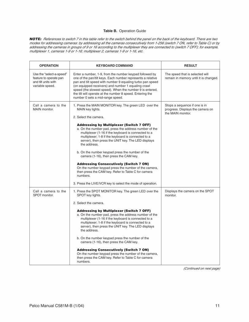
Table B. Operation Guide
NOTE: References to switch 7 in this table refer to the switch behind the panel on the back of the keyboard. There are twomodes for addressing cameras: by addressing all the cameras consecutively from 1-256 (switch 7 ON, refer to Table C) or byaddressing the cameras in groups of 9 or 16 according to the multiplexer they are connected to (switch 7 OFF); for example,multiplexer 1, cameras 1-9 or 1-16; multiplexer 2, cameras 1-9 or 1-16, etc.
OPERATION KEYBOARD COMMAND RESULT
Enter a number, 1-9, from the number keypad followed byone of the pan/tilt keys. Each number represents a relativepan and tilt speed with number 9 equaling turbo pan speed(on equipped receivers) and number 1 equaling crawlspeed (the slowest speed). When the number 9 is entered,the tilt will operate at the number 8 speed. Entering thenumber 0 sets a mid-range speed.
1. Press the MAIN MONITOR key. The green LED over theMAIN key lights.
2. Select the camera.
Addressing by Multiplexer (Switch 7 OFF)a. On the number pad, press the address number of the
multiplexer (1-16 if the keyboard is connected to amultiplexer; 1-8 if the keyboard is connected to aserver), then press the UNIT key. The LED displaysthe address.
b. On the number keypad press the number of thecamera (1-16), then press the CAM key.
Addressing Consecutively (Switch 7 ON)On the number keypad press the number of the camera,then press the CAM key. Refer to Table C for cameranumbers.
3. Press the LIVE/VCR key to select the mode of operation.
1. Press the SPOT MONITOR key. The green LED over theSPOT key lights.
2. Select the camera.
Addressing by Multiplexer (Switch 7 OFF)a. On the number pad, press the address number of the
multiplexer (1-16 if the keyboard is connected to amultiplexer; 1-8 if the keyboard is connected to aserver), then press the UNIT key. The LED displaysthe address.
b. On the number keypad press the number of thecamera (1-16), then press the CAM key.
Addressing Consecutively (Switch 7 ON)On the number keypad press the number of the camera,then press the CAM key. Refer to Table C for cameranumbers.
Call a camera to theMAIN monitor.
Call a camera to theSPOT monitor.
(Continued on next page)
Stops a sequence if one is inprogress. Displays the camera onthe MAIN monitor.
Displays the camera on the SPOTmonitor.
Use the “select-a-speed”feature to operate panand tilt units withvariable speed.
The speed that is selected willremain in memory until it is changed.

12 Pelco Manual C581M-B (1/04)
Table B. Operation Guide (Continued)
1. Go to the Advanced System Setup menu.
2. Press the pan/tilt keys so the cursor highlights SPOTMONITOR DISPLAY items.
3. Press the OPEN key until TRACK MAIN is displayed.
4. Exit the Advanced System Setup menu.
1. Go to the Advanced System Setup menu.
2. Press the pan/tilt keys so the cursor highlights SPOTMONITOR DISPLAY items.
3. Press the OPEN key until either SEQUENCE or BLANKis displayed.
4. Exit the Advanced System Setup menu.
1. Press the MAIN MONITOR key. The green LED over theMAIN key lights.
2. On the number pad, press the address number of themultiplexer (1-16 if the keyboard is connected to amultiplexer; 1-8 if the keyboard is connected to aserver), then press the UNIT key. The LED displays theaddress.
3. Press the key below the 4, 9, or 16 icon.
4. Repeat pressing the key until the correct group isdisplayed (4 or 9 only).
5. Press the LIVE/VCR key to select the mode ofoperation.
OPERATION KEYBOARD COMMAND RESULT
(Continued on next page)
Exit main tracking.
Call a group of camerasto the MAIN monitor.
Exits main tracking mode.
Displays the group of cameras onthe MAIN monitor.
Set main tracking. Spot monitor follows the cameraswitching that occurs on the mainmonitor in single screen mode. Inmulti-screen mode, the spotmonitor switches to camera 1.
Allows only P/T/Z control while inmain monitor mode. Press theSPOT key to have presets andpatterns while in this mode.

Pelco Manual C581M-B (1/04) 13
Table B. Operation Guide (Continued)
1. Press the MAIN MONITOR key. The green LED over theMAIN key lights.
2. Select the camera that you want to display full size.
Addressing by Multiplexer (Switch 7 OFF)a. On the number pad, press the address number of the
multiplexer (1-16 if the keyboard is connected to amultiplexer; 1-8 if the keyboard is connected to aserver), then press the UNIT key. The LED displaysthe address.
b. On the number keypad press the number of thecamera (1-16), then press the CAM key.
Addressing Consecutively (Switch 7 ON)On the number keypad press the number of thecamera, then press the CAM key. Refer to Table C forcamera numbers.
3. Make sure the main monitor displays live video. If thevideo is not live, press the LIVE/VCR key.
4. Press the PIP icon key.
5. On the number keypad press the number of the camerayou want to display in the insert. Then press the CAMkey. (Note: Both cameras must be connected to thesame multiplexer.)
6. To change the display in the insert, press the number ofthe camera, then press the CAM key.
7. To exit, press the PIP icon key.
1. Press the MAIN MONITOR key. The green LED overthe MAIN key lights.
2. Select the camera.
Addressing by Multiplexer (Switch 7 OFF)a. On the number pad, press the address number
of the multiplexer (1-16 if the keyboard is connectedto a multiplexer; 1-8 if the keyboard is connected to aserver), then press the UNIT key. The LED displaysthe address.
b. On the number keypad press the number of thecamera (1-16), then press the CAM key.
Addressing Consecutively (Switch 7 ON)On the number keypad press the number of thecamera, then press the CAM key. Refer to Table C forcamera numbers.
3. Press the LIVE/VCR key to select the mode ofoperation.
4. Press the key below the ZOOM icon. The zoomwill be 2X. Press the key again for 4X zoom.
5. Use the pan/tilt keys to control the zoom location.
6. To exit, press the zoom icon key or the number of thecamera, then press the CAM key.
OPERATION KEYBOARD COMMAND RESULT
(Continued on next page)
Zoom on a camera onthe MAIN monitor.
Stops a sequence if one is inprogress. Displays a 2X or 4Xzoom of the camera selected onthe MAIN monitor.
Display a picture-in-picture (PIP) insert onthe MAIN monitor.
The full-size view appears on theMAIN monitor with the PIP insert.
NOTE: In order to change thecamera shown on the full screenview, you must exit the PIP mode.

14 Pelco Manual C581M-B (1/04)
Table B. Operation Guide (Continued)
1. Press the MAIN MONITOR key. The green LED over theMAIN key lights.
2. Select a camera on the multiplexer that you want tosequence.
Addressing by Multiplexer (Switch 7 OFF)a. On the number pad, press the address number of the
multiplexer (1-16 if the keyboard is connected to amultiplexer; 1-8 if the keyboard is connected to aserver), then press the UNIT key. The LED displaysthe address.
b. On the number keypad press the number of acamera (1-16), then press the CAM key.
Addressing Consecutively (Switch 7 ON)On the number keypad press the number of a camera,then press the CAM key. Refer to Table C for cameranumbers.
3. Press the LIVE/VCR key to select the mode ofoperation.
4. To sequence individual cameras, go to step 5. Tosequence groups of cameras, press the key below the4- or 9-screen icon, then go to step 5.
5. Press the SEQ key.
1. Press the SPOT MONITOR key. The green LED overthe SPOT key lights.
2. Select a camera on the multiplexer that you want tosequence.
Addressing by Multiplexer (Switch 7 OFF)a. On the number pad, press the address number of the
multiplexer (1-16 if the keyboard is connected to amultiplexer; 1-8 if the keyboard is connected to aserver), then press the UNIT key. The LED displaysthe address.
b. On the number keypad press the number of acamera (1-16), then press the CAM key.
Addressing Consecutively (Switch 7 ON)On the number keypad press the number of a camera,then press the CAM key. Refer to Table C for cameranumbers.
3. Press the SEQ key.
1. Press the MAIN or SPOT MONITOR key.
2. On the number pad, press the address number of themultiplexer (1-16 if the keyboard is connected to amultiplexer; 1-8 if the keyboard is connected to aserver), then press the UNIT key. The LED displays theaddress.
3. Press the SEQ key.
OPERATION KEYBOARD COMMAND RESULT
Starts the sequence of individualcameras on the SPOT monitor.
Stops the sequence. The monitordisplays video from the camera onwhich sequence stops.
Run a sequence ofcameras from onemultiplexer on theSPOT monitor. (SPOTMONITOR DISPLAY inthe Advance SystemSetup menu must be inSEQUENCE.)
Stop a sequence ofcameras on amultiplexer.
(Continued on next page)
Run a sequence ofcameras from onemultiplexer on theMAIN monitor.
Starts the pre-programmedsequence of individual cameras orgroups of cameras on the MAINmonitor.

Pelco Manual C581M-B (1/04) 15
1. Select the desired multi-camera display.
2. Press and hold the multi-camera display key to enterthe multi-screen programming mode. A bar will appearin the first camera location.
3. Use the pan/tilt keys to move the on-screen bar to thedesired camera location for sequencing, and presssequence key to initiate the sequencing of all activecameras.
1. Hold down the SEQ key for approximately threeseconds.
1. Follow the steps under “Run a sequence of camerasfrom one multiplexer on the MAIN monitor” or “Run asequence of cameras from one multiplexer on theSPOT monitor” to start sequencing the cameras on themain and spot monitors of individual multiplexers thatyou want to sequence.
2. Hold down the SEQ key for approximately threeseconds to start sequencing the multiplexers.
1. Press the key.
2. Press the SEQ key.
Press a pan/tilt key or select any camera.
Program the monitor in the Advanced System Setupmenu.
Table B. Operation Guide (Continued)
Starts sequencing the multiplexersin numerical order, displaying themain monitor first, then the spotmonitor. Monitors to be displayedare selected in the Set Sequencesubmenu of the Monitor menu ofthe server. As each monitor isdisplayed, it sequences.Sequencing appears on themonitor affiliated with the key-board; for example, if the keyboardis set for address 1, the sequencewill appear on monitor 1.
Sequences all active cameras inthe PIP display.
OPERATION KEYBOARD COMMAND RESULT
(Continued on next page)
Stop a sequence ofmultiplexers.
Call a camera or run asequence of camerason the AUX monitor(duplex multiplexeronly).
Sequence multiplexersconnected to a serverand sequence camerason a multiplexer(s).
Sequence the PIPdisplay.
Sequence stops.
Monitor responds to programminginstructions.
Starts sequencing the multiplexersin numerical order, displaying themain monitor first, then the spotmonitor. Monitors to be displayedare selected in the Set Sequencesubmenu of the Monitor menu ofthe server. Sequencing appears onthe monitor affiliated with thekeyboard; for example, if thekeyboard is set for address 1, thesequence will appear on monitor 1.
Sequence multiplecameras in onelocation of a 4-, 9-, or16-camera display.
Sequence multiplexersconnected to a server.
The sequence will run until thesequence key is pressed or untilanother camera or multi-screendisplay has been selected.

16 Pelco Manual C581M-B (1/04)
1. Press the MAIN or SPOT MONITOR key. The greenLED over the MAIN or SPOT key lights. When using theMAIN MONITOR, the SPOT MONITOR DISPLAY menuitem in the Advanced System Setup menu must beset to TRACK MAIN (refer to the Advanced SystemSetup section).
2. Select the camera.
Addressing by Multiplexer (Switch 7 OFF)a. On the number pad, press the address number of the
multiplexer (1-16 if the keyboard is connected to amultiplexer; 1-8 if the keyboard is connected to aserver), then press the UNIT key. The LED displaysthe address.
b. On the number keypad press the number of thecamera (1-16), then press the CAM key.
Addressing Consecutively (Switch 7 ON)On the number keypad press the number of thecamera, then press the CAM key. Refer to Table C forcamera numbers.
3. On the number keypad press the number of the preset,then press the PRESET key. (Note: When calling preset95 on Esprit™ or Spectra® systems, hold the PRESETkey until the menu appears on the screen.)
1. Press the SPOT MONITOR key. The green LED overthe SPOT key lights.
2. Select the camera.
Addressing by Multiplexer (Switch 7 OFF)a. On the number pad, press the address number of the
multiplexer (1-16 if the keyboard is connected to amultiplexer; 1-8 if the keyboard is connected to aserver), then press the UNIT key. The LED displaysthe address.
b. On the number keypad press the number of thecamera (1-16), then press the CAM key.
Addressing Consecutively (Switch 7 ON)On the number keypad press the number of thecamera, then press the CAM key. Refer to Table C forcamera numbers.
3. On the number keypad press 97, then press thePRESET key.
With system in auto scan, press 97 on the numberkeypad, then press the PRESET key.
Table B. Operation Guide (Continued)
OPERATION KEYBOARD COMMAND RESULT
(Continued on next page)
Start random scanwith 15-bit receiver.
Starts random scanning.
Start auto scan with15-bit receiver.
Starts auto scanning.
Call a preset. Moves the camera to the presetlocation.

Pelco Manual C581M-B (1/04) 17
1. Press the SPOT MONITOR key. The green LED overthe SPOT key lights.
2. Select the camera.
Addressing by Multiplexer (Switch 7 OFF)a. On the number pad, press the address number of the
multiplexer (1-16 if the keyboard is connected to amultiplexer; 1-8 if the keyboard is connected to aserver), then press the UNIT key. The LED displaysthe address.
b. On the number keypad press the number of thecamera (1-16), then press the CAM key.
Addressing Consecutively (Switch 7 ON)On the number keypad press the number of thecamera, then press the CAM key. Refer to Table C forcamera numbers.
3. On the number keypad press 96, then press thePRESET key.
1. Press the MAIN or SPOT MONITOR key. The greenLED over the MAIN or SPOT key lights. When using theMAIN MONITOR, the SPOT MONITOR DISPLAY menuitem in the Advanced System Setup menu must beset to TRACK MAIN (refer to the Advanced SystemSetup section).
2. Select the camera.
Addressing by Multiplexer (Switch 7 OFF)a. On the number pad, press the address number of the
multiplexer (1-16 if the keyboard is connected to amultiplexer; 1-8 if the keyboard is connected to aserver), then press the UNIT key. The LED displaysthe address.
b. On the number keypad press the number of thecamera (1-16), then press the CAM key.
Addressing Consecutively (Switch 7 ON)On the number keypad press the number of thecamera, then press the CAM key. Refer to Table C forcamera numbers.
3. On the number keypad press 1, then press thePATTERN key.
4. To stop the pattern, press a pan/tilt key.
Table B. Operation Guide (Continued)
OPERATION KEYBOARD COMMAND RESULT
(Continued on next page)
Begin a pattern. The pattern operates until stopped.
Stops auto or random scanning, ifoperating, and activates manualscanning.
Start manual scan (orstop auto or randomscan) with 15-bitreceiver.

18 Pelco Manual C581M-B (1/04)
OPERATION KEYBOARD COMMAND RESULT
Table B. Operation Guide (Continued)
1. Press the SPOT MONITOR key. The green LED overthe SPOT key lights.
2. Select the camera.
Addressing by Multiplexer (Switch 7 OFF)a. On the number pad, press the address number of the
multiplexer (1-16 if the keyboard is connected to amultiplexer; 1-8 if the keyboard is connected to aserver), then press the UNIT key. The LED displaysthe address.
b. On the number keypad press the number of thecamera (1-16), then press the CAM key.
Addressing Consecutively (Switch 7 ON)On the number keypad press the number of thecamera, then press the CAM key. Refer to Table C forcamera numbers.
3. On the number keypad press the number of theauxiliary you want to operate, then press the AUX ON orOFF key.
For duplex multiplexer, recording is done automatically.For simplex multiplexer, the multiplexer must be in therecord mode (DISPLAY/RECORD LED is ON).
1. Press the MAIN MONITOR key. The green LED over theMAIN key lights.
2. On the number pad, press the address number of themultiplexer (1-16 if the keyboard is connected to amultiplexer; 1-8 if the keyboard is connected to aserver), then press the UNIT key. The LED displays theaddress.
3. Press the LIVE/VCR key to put the multiplexer in theplayback mode.
4. Select the cameras to play back from one of thefollowing choices:
• For an individual camera, press the number of thecamera, then press the CAM key. If switch 7 is OFF,enter a camera number from 1-16. If switch 7 is ON,refer to Table C for camera numbers.
• For multiple camera display, press the key below the4, 9, or 16 icon.
• For sequencing, select an individual or multiplecamera display, then press the SEQ button.
5. Turn on the VCR and press the PLAY button.
Play a tape. Displays the recorded cameras inthe selected format on the MAINmonitor.
Turn an auxiliaryfunction on or off.
The auxiliary function operates.
Records all cameras connected tothe multiplexer.
For simplex multiplexer, while themultiplexer is in the record mode(DISPLAY/RECORD LED on ON)you can only see a full-screen viewof one camera (or one camera at atime if sequencing) on the mainmonitor, but all active cameras arebeing recorded.
Record a tape.

Pelco Manual C581M-B (1/04) 19
PROGRAMMING
This section applies only to programming the multiplexer. To program themultiplexer server, refer to the server manual.
Programming allows you to configure the multiplexer from the KBD4002 for the way thatyou want your system to operate. The multiplexer automatically selects the most commonoperating parameters. However, some minimal programming may be required to make yoursystem work.
Programming of system, camera, and VCR setup; camera sequencing; and alarm and ac-tivity detection are done through on-screen menus that are displayed on the main monitor.A password can be enabled to prevent unauthorized access to the menus.
Programming of the picture-in-picture, and 4-, 9-, and 16-camera displays can be donedirectly without going through menus.
IMPORTANT NOTEBefore the keyboard can be used to control the multiplexer(s), perform the following steps atthe multiplexer(s) front panel.
1. Press the VIEW button for approximately three seconds. The basic SYSTEM Setupmenu appears.
2. The currently selected menu item blinks. Use the arrow buttons to highlight AD-VANCED SETUP.
3. Press the +/- button. The Advanced System Setup menu appears. Skip steps 4 and 5 ifyour system has only one multiplexer.
4. Use the arrow buttons to move the cursor to UNIT ID.
5. Press the +/- button to select the UNIT ID of the multiplexer.
6. Use the arrow button to move the cursor to COMM.TYPE.
7. In the polled communication mode (switch 4 OFF), one multiplexer must be themaster and all others slaves. In the non-polled mode (switch 4 ON), all multiplexersmust be slaves.
8. Use the arrow button to go to EXIT. Press the +/- button to exit the menu. The keyboardcan now be used to program the multiplexer(s).
NOTE: Whenever amultiplexer server isinstalled, programming themultiplexer must be doneat the multiplexer frontpanel. In this situation, themultiplexer cannot beprogrammed from the+keyboard. The keyboardcan only be used toprogram the multiplexerserver, not the multiplexer.
Table C. Camera Numbers with Switch 7 ON
Multiplexer Cameras9-channel 16-channel
1 1-9 1-16
2 17-25 17-32
3 33-41 33-48
4 49-57 49-64
5 65-73 65-80
6 81-89 81-96
7 97-105 97-112
8 113-121 113-128
9 129-137 129-144
10 145-153 145-160
11 161-169 161-176
12 177-185 177-192
13 193-201 193-208
14 209-217 209-224
15 225-233 225-240
16 241-249 241-256

20 Pelco Manual C581M-B (1/04)
PASSWORD
You can program the multiplexer to request a password for access to programming menus.The password is enabled in the Advanced System Setup menu (refer to the AdvancedSystem Setup section).
The universal password is 3916 and cannot be changed. This password must be enteredwhenever one is requested. The password is entered from the keyboard by pressing eachnumber followed by pressing the CAM key: 3, CAM, 9, CAM, 1, CAM, 6, CAM.
MENUS
To program from the keyboard you have to be in main monitor mode. Press the MAINMONITOR key.
SYSTEM SETUP (View Key)To program the main basic system parameters:
1. Press the MAIN MONITOR key.
2. Use the number keypad to enter the address of the multiplexer (1-16 if the keyboard isconnected to a multiplexer; 1-8 if the keyboard is connected to a server), then pressthe UNIT key.
3. Press the VIEW key for approximately three seconds. Type the password, if requested.The password must be entered by pressing each number key followed by pressing theCAM key. The System Setup menu appears. The currently selected menu item blinks.
4. Use the pan/tilt keys to move between items on the screen. When the menu item youdesire is highlighted (blinking), do one of the following:
• If a menu item has more than one option, press the OPEN key to cycle throughthe options to select the one you want.
• If a menu item has only one option, press the OPEN key to select it.
Time and DateSet the current time and date. The time uses a 24-hour clock.
Time DisplayON - Displays the time on the main monitor.OFF - The time is not shown on the main monitor.
TIP: Once you are in amenu, you can go to anothermenu by pressing the key(s)for that menu. Press andrelease the VIEW key toswitch to the system setupmenu. Enter a cameranumber and then press andrelease the CAM key tochange to a camera menu.Press and hold the SEQ andLIVE/VCR keys to switch tothe sequence and recordmenus.
TIP: In any menu you canscroll the options forward bypressing the OPEN key orscroll backward by pressingthe CLOSE key.
Figure 3. Basic System Setup Menu
2/6/8 Hr2/6/8 Hr
MAIN MONITOR VIDEO
RESET ACTIVITY DETECTION ALL CH TO
*2,6,or 8 Hr 120 Hr 12 Hr 168 Hr 16 Hr 180 Hr 18 Hr 240 Hr 24 Hr 360 Hr 48 Hr 480 Hr 72 Hr 600 Hr 84 Hr 720 Hr 96 Hr 960 Hr
HIGH RESOLUTIONREDUCED FLICKER
MAIN MONITOR DISPLAY HIGH RESOLUTION
**
* 2/6/8 HR FOR NTSC/EIA MODEL MULTIPLEXERS, 3 HR FOR PAL/CCIR MODELS. REMAINING RECORD SPEEDS DEPEND UPON VCR MODEL. ** NOT SHOWN ON DUPLEX MONOCHROME MODELS OR SIMPLEX MULTIPLEXERS
**

Pelco Manual C581M-B (1/04) 21
Title Display (Duplex Multiplexer)ON - Displays camera titles and the word LIVE or VCR on the main monitor.OFF - Camera titles and the word LIVE or VCR are not shown on the main monitor.
Title Display (Simplex Multiplexer)ON - Displays camera titles on the main monitor.OFF - Camera titles are not shown on the main monitor.
Record SpeedsSets the speed at which the VCR normally records video and the speed at which itrecords when there is an alarm(s). Setting the speeds in the System Setup menu alsosets the speeds in the Record Setup and Custom VCR Setup menus.
Main Monitor Video (Duplex Multiplexer Color Models Only)Composite is standard video on coaxial cable. SVHS is higher resolution video on aspecial cable.
Main Monitor DisplayThe options are High Resolution or Reduced Flicker. Reduced Flicker can be selectedwhen there is flickering on the monitor screen, such as from a neon light. This problemis more visible to the eye in PAL format multiplexers.
GLOBAL SETUPS
Video TerminationsThese settings set the terminations for all video inputs. To set individual inputs, referto the Camera Setup section.
Set to 75 OHM when equipment is connected only to the video IN connectors. Theremust be no equipment connected to the video OUT connectors.
Set to LOOP HI-Z when equipment is connected to the video OUT (looping) connectors.For every channel that has equipment connected to the video IN connector, theremust be equipment connected to the video OUT connector. Do not use this globalsetting if any channel has equipment connected to a video input but no equipmentconnected to the video output. Equipment connected to the looping connectors mustbe terminated at 75 ohms.
NO CHANGE - This is a pass-through selection in case you unintentionally hit theOPEN key. This is not an undo key.
Alarm InputsNormally closed operation = current flow = alarm switch or relay closed.Normally open operation = no current flow = alarm switch or relay open.
Dwell RatesSets the sequence dwell rate for all cameras. To set individual dwell rates forcameras, refer to the Sequence Setup section.
Activity DetectionENABLED/DISABLED - Turns activity detection on or off for all video inputs. To setindividual inputs, refer to the Camera Setup section.
NO CHANGE - This is a pass-through selection in case you unintentionally hit theOPEN key. This is not an undo key.
5. When you have completed all the changes you want to make, go to EXIT orADVANCED SETUP.
6. Press the OPEN key to exit the programming mode or to go to the advanced systemsetup menu.
When HELP is highlighted, you may press the OPEN key to display a help screen that willtell you which keys to press to configure specific options.
NOTE: Title Display shows amaximum of 12 characters inall modes except 16-cameradisplay, in which only 9 char-acters are shown.

22 Pelco Manual C581M-B (1/04)
ADVANCED SYSTEM SETUP (View Key)To program the advanced main system parameters:
1. Press the MAIN MONITOR key.
2. Use the number keypad to enter the address of the multiplexer (1-16 if the keyboard isconnected to a multiplexer; 1-8 if the keyboard is connected to a server), then pressthe UNIT key.
3. Press the VIEW key for approximately three seconds. The basic System Setup menuappears.
4. The currently selected menu item blinks. Use the pan/tilt keys to highlight ADVANCEDSETUP.
5. Press the OPEN key. The Advanced System Setup menu appears.
6. Use the pan/tilt keys to move between items on the screen. When the menu item youdesire is highlighted (blinking), press the OPEN key to cycle through the options.
Date FormatSets the format for displaying the date on the main monitor.
PasswordEnables or disables password control to access programming menus.
Front Panel ControlEnables or disables the front panel buttons to operate the multiplexer. In either modeyou can access programming menus. Has no effect on the keyboard.
Main Monitor DisplaySelect ALARMS, ACTIVITY, or ALARMS/ACTIVITY if you want the main monitor toswitch to cameras that have alarms or activity detection. If you are using the mainmonitor for normal video and you do not want alarms or activity detection to overridewhat you are observing, select NONE.
Figure 4. Advanced System Setup Menu
ALL COLOR*COLOR & B/WRESERVED
DATE FORMAT MM-DD-YYPASSWORD DISABLEDFRONT PANEL CONTROL ENABLED
MAIN MONITOR DISPLAYRESPONDS TO NONE
SPOT MONITOR DISPLAY SEQUENCERESPONDS TO ALARMS
AUX MONITOR DISPLAY BLANKRESPONDS TO ACTIVITY
CAMERA TYPES ALL COLOR
UNIT ID 001COMM. TYPE MASTER (KBD-T/D)
RELAY OUTPUT ALARM
MASTER (KBD-T/D)** (1)SLAVE (2)
001–240
SEQUENCEBLANKTRACK MAIN
* ALL B/W SHOWN ON MONOCHROME MODELS. (1) SIMPLEX DEFAULT SETTING** MUST BE SET IN THIS MODE FROM THE FRONT PANEL OF THE (2) DUPLEX DEFAULT SETTING
MULTIPLEXER TO PROGRAM THE MULTIPLEXER FROM THE KEYBOARD.*** DUPLEX MULTIPLEXER ONLY; NOT ON SIMPLEX
BLANKCAM 1
CAM 16SEQUENCE
******

Pelco Manual C581M-B (1/04) 23
Spot Monitor DisplayIf you want the spot monitor to switch to cameras that have alarms or activitydetection, select BLANK, SEQUENCE, or TRACK MAIN, then under RESPONDS TOselect ALARMS, ACTIVITY, or ALARMS/ACTIVITY. If you are using the spot monitorfor normal video and you do not want alarms or activity detection to override what youare observing, select NONE.
BLANK - Allows you to view an individual camera, but you cannot run a sequence. Analarm or activity detection will override the camera you are viewing. When the alarm oractivity detection goes away, the screen will return to the camera you were viewing.
SEQUENCE - Allows you to view an individual camera or run a sequence. An alarm oractivity detection will override what you are observing. When the alarm or activitydetection goes away, the screen will return to the camera or sequence you wereviewing.
TRACK MAIN - The spot monitor will follow the camera switching that occurs on themain monitor. This feature is used only when a KBD4002 keyboard is connected to themultiplexer for controlling moveable cameras. This mode provides an easy method ofsimplifying P/T/Z control in single-monitor applications. The operator does not have toswitch to SPOT to gain P/T/Z control and there is no separate control of the spotmonitor when in this mode. However, to do presets and patterns, switch to SPOT.
Aux Monitor Display (Duplex Multiplexer Only)Select ALARMS, ACTIVITY, or ALARMS OR ACTIVITY if you want the auxiliarymonitor to show cameras with alarms or activity detection. If you are using theauxiliary monitor to sequence all cameras and you do not want alarms or activitydetection to override the sequence, select NONE.
BLANK - This means the screen will remain blank unless there is an alarm or activitydetection.
SEQUENCE - This means the monitor will sequence all cameras unless there is analarm or activity detection.
CAM 1 through CAM 16 - This means the monitor will display the selected cameraunless there is an alarm or activity detection.
Camera TypesThe COLOR & B/W setting allows the multiplexer to adapt to the combination of bothcolor and monochrome video signals. The switching speed of the multiplexer is not asfast when it has to change formats between monochrome and color cameras. Forduplex monochrome models, you will not receive color from a color camera excepton the SPOT or AUX monitor displays. For simplex monochrome models, you willnot receive color from a color camera except in RECORD mode.
The RESERVED setting can improve performance when using cameras withnon-standard sync or poor video quality.
Unit IDThis is the address of the multiplexer. If your system has more than one multiplexer,each multiplexer must have its own address. This must be set at the multiplexer, not atthe keyboard.
Comm.TypeIn the polled communication mode (switch 4 OFF), one multiplexer (any one) mustbe the master. Only one multiplexer can be the master. All other multiplexers must beslaves. The master multiplexer communicates with the slave multiplexers.
In the non-polled communication mode (switch 4 ON), all multiplexers must beslaves.
The default is SLAVE for duplex multiplexers and MASTER (KBD T/D) for simplexmultiplexers.
CAUTION: Whenprogramming theMX4000
Multiplexer from theKBD4002 Keyboard, DONOT ATTEMPT TOCHANGE THE UNIT ID.Changing the unit ID fromthe keyboard will interruptthe keyboardcommunications to themultiplexer, resulting inerratic multiplexer operation.Refer to the Troubleshootingsection, in this manual tocorrect the situation.

24 Pelco Manual C581M-B (1/04)
Relay OutputOperates the relay on the back of the multiplexer. The relay is used to change the VCRto its alarm recording speed. In the alarms mode, an alarm signal is produced when aremote switch opens or closes a ground in the multiplexer; for example, if a switch ison a door and the door is opened. In the activity mode, the multiplexer continuallymonitors select camera inputs for motion. When motion is detected, the multiplexer increases the frequency with which that camera(s) is shown and recorded. Activitydetection is most effective when only a few cameras are showing activity (refer to theCamera Setup section).
7. When you have completed all the changes you want to make, go to EXIT or BASIC SETUP.
8. Press the OPEN key to exit the programming mode or to go to the basic system setupmenu.
When HELP is highlighted, you may press the OPEN key to display a help screen that willtell you which keys to press to configure specific options.
RECORD SETUP (Live/VCR Key)To program the VCR recording parameters:
1. Press the MAIN MONITOR key.
2. Use the number keypad to enter the address of the multiplexer (1-16 if the keyboard isconnected to a multiplexer; 1-8 if the keyboard is connected to a server), then pressthe UNIT key.
3. Press the LIVE/VCR key for approximately three seconds. Type the password,if requested. The Record Setup menu appears. The currently selected menu itemblinks.
4. Use the pan/tilt keys to move between items on the screen. When the menu item youdesire is highlighted (blinking), press the OPEN key to cycle through the options toselect the one you want.
Record SpeedsSets the speed at which the VCR normally records video and the speed at which itrecords when there is an alarm(s). Setting the speeds in the Record Setup menu alsosets the speeds in the System Setup and Custom VCR Setup menus.
VCR Type (See Table D)If your VCR is not listed among the options, do either of the following:
• Select UNIVERSAL. In the recording speed menu item at the top of the screen,select an option that your VCR will support.
• Select CUSTOM. Then go to CONFIGURE CUSTOM VCR and press the OPENkey to go to the Custom VCR Setup menu. The switch interval can be changed onlywhile in this setting.
VCR Video FormatThis feature is not available on monochrome multiplexers. Composite is standardvideo on a coaxial cable. SVHS is higher resolution video on a special cable.
VCR Switch PulseENABLED means the multiplexer waits for a head switching pulse from the VCR. If themultiplexer does not get a pulse from the VCR (because of a broken wire or the VCRdoes not give a pulse in some modes), it may appear that the multiplexer is notworking properly.
DISABLED means the VCR head switching pulse is not used.
Alarm HandlingDetermines how alarms are recorded and for how long.
Configure Custom VCRPress the OPEN key to get to the CUSTOM VCR SETUP menu.
Playback FormatTapes made using Pelco, Robot, and DM multiplexers can be played.

Pelco Manual C581M-B (1/04) 25
Figure 5. Basic VCR Setting Menu
Table D. VCR Types
NTSC PAL
UNIVERSAL UNIVERSALGYYR TLC1800 ASUTA TLVCR 251GYYR 2100 ASUTSA TLVCR 964GYYR 2100 HD MODE BURLE TC3910XJVC SR-L900U HITACHI VTL30EJVC SR-L901U HITACHI VT-L1000EJVC SR-9070U HITACHI VT-L2000EJVC BR-S925U JVC BR9060EMITSUBISHI HS7424U JVC BR-S920/925MITSUBISHI HS7496U JVC SR-L900EMITSUBISHI HS5168U MITS. HS5300/5600MITS. HS7168U NORM MITS. HS5424EMITS. HS7168U HD PANAS. AG6024/6124PANASONIC AG-RT600 PANASONIC AG6720PANASONIC AG6124 PANASONIC AG6730PANASONIC AG 6730 PANASONIC AG6040PELCO TLR2024 SANYO TLS900PPELCO TLR2096 SANYO TLS1000PELCO TLR2168 NORM SANYO SRT-500PPELCO TLR2168HD SANYO TLS2000SANYO SRT600 SONY SVT100PSANYO TLS924/972 SONY SVT5000PSANYO TLS2500/7000 CUSTOMTOSHIBA KV6300TOSHIBA KV7024ATOSHIBA KV7168ATOSHIBA KV7960ATOSHIBA KV8168ACUSTOM
****
ALARM DURATION30 SECONDS1 MINUTE2 MINUTES5 MINUTES10 MINUTES15 MINUTES
ENABLEDDISABLED
*2,6,or 8 Hr 24 Hr 96 Hr 240 Hr 12 Hr 48 Hr 120 Hr 360 Hr 16 Hr 72 Hr 168 Hr 480 Hr 18 Hr 84 Hr 180 Hr 600 Hr 720 Hr 960 Hr
PELCOROBOTDM
SEE TABLE D
* 2/6/8 HR FOR NTSC/EIA MODEL MULTIPLEXERS, 3 HOUR FOR PAL/CCIR MODELS. REMAINING RECORD SPEEDS DEPEND UPON VCR MODEL. ** NOT SHOWN ON MONOCHROME MODELS.
NORMAL REC. SPEED 2/6/8 HrALARM REC. SPEED 2/6/8 Hr
VCR SETUP
VCR TYPE UNIVERSALVCR VIDEO FORMAT COMPOSITEVCR SWITCH PULSE DISABLED
ALARM HANDLING
RECORD ALARMS AS A PRIORTIYALARM RECORD TIME ALARM DURATION
CONFIGURE CUSTOM VCR
PLAYBACK FORMAT PELCO

26 Pelco Manual C581M-B (1/04)
5. When you have completed all the changes you want to make, go to EXIT.
6. Press the OPEN key to exit the programming mode.
When HELP is highlighted, you may press the OPEN key to display a help screen that willtell you which keys to press to configure specific options.
CUSTOM VCR SETUP (Live/VCR Key)To program the advanced VCR parameters:
1. Press the MAIN MONITOR key.
2. Use the number keypad to enter the address of the multiplexer (1-16 if the keyboard isconnected to a multiplexer; 1-8 if the keyboard is connected to a server), then pressthe UNIT key.
3. Press the LIVE/VCR key for approximately three seconds. The Record Setup menuappears. The currently selected menu item blinks.
4. Make sure the VCR Type in the Record Setup menu is set to CUSTOM.
5. Use the pan/tilt keys to highlight CONFIGURE CUSTOM VCR.
6. Press the OPEN key. The Custom VCR Setup menu appears.
7. Use the pan/tilt keys to move between items on the screen. When the menu item youdesire is highlighted (blinking), press the OPEN key to cycle through the options.
Record SpeedsSets the speed at which the VCR normally records video and the speed at which itrecords when there is an alarm(s).
Setting the speeds in the Custom VCR Setup menu also sets the speeds in the SystemSetup and Record Setup menus.
IntervalInterval is the number of fields recorded by the VCR before switching to the next camera.
8. When you have completed all the changes you want to make, go to EXIT or BACK.
9. Press the OPEN key to exit the programming mode or to return to the Record Setupmenu.
When HELP is highlighted, you may press the OPEN key to display a help screen that willtell you which keys to press to configure specific options.
NOTE: For proper record-ing, the switching rate of themultiplexer must match thatof the VCR. If they do notmatch, the VCR may skipframes or record duplicateframes.
Figure 6. Custom VCR Setup Menu
NORMAL RECORD SETUP
RECORD SPEED 2/6/8 HrSWITCH INTERVAL 003
ALARM RECORD SETUP
RECORD SPEED 2/6/8 HrSWITCH INTERVAL 003
EXIT BACK
003 TO 509 **
*2,6,or 8 Hr 120 Hr 12 Hr 168 Hr 16 Hr 180 Hr 18 Hr 240 Hr 24 Hr 360 Hr 48 Hr 480 Hr 72 Hr 600 Hr 84 Hr 720 Hr 96 Hr 960 Hr
*2/6/8 HR FOR NTSC/EIA MODEL MULTIPLEXERS, 3 HR FOR PAL/CCIR MODELS.REMAINING RECORD SPEEDS DEPEND UPON VCR MODEL.
** VCR TYPE IN RECORD SETUP MENU MUST BE SET TO CUSTOM IN ORDER TO MAKE SELECTIONS.

Pelco Manual C581M-B (1/04) 27
CAMERA SETUP (Number and CAM Keys)To program a camera input:
1. Press the MAIN MONITOR key.
2. Select the camera.
Addressing by Multiplexer (Switch 7 OFF)a. On the number keypad, enter the address number of the multiplexer (1-16 if the
keyboard is connected to a multiplexer; 1-8 if the keyboard is connected to aserver), then press the UNIT key.
b. On the number keypad, enter the number of the camera, then press and hold theCAM key until the Camera menu appears.
Addressing Consecutively (Switch 7 ON)On the number keypad, enter the number of the camera, then press and hold the CAMkey until the Camera menu appears. Refer to Table C for camera numbers.
3. A video insert appears that shows what the camera is viewing. This is useful to makesure you have selected the correct camera and to see what effect there is on the videowhen you select a menu option. The currently selected menu item blinks.
4. Use the pan/tilt keys to move between items on the screen. When the menu item youdesire is highlighted (blinking), press the OPEN key to cycle through the options toselect the one you want. Use the right pan key to advance to the next characterposition when titling a camera.
Video TerminationSet to 75 OHM when equipment is connected only to the video IN connector.
Set to LOOP HI-Z when equipment is also connected to the video OUT (looping)connector. Equipment connected to the looping connector must be terminated at 75ohms.
Alarm InputNormally closed operation = current flow = alarm switch or relay closed.Normally open operation = no current flow = alarm switch or relay open.
Figure 7. Basic Camera Menu
OPENCLOSEDDISABLED
VIDEO INPUT TERMINATION 75 OHMALARM INPUT NORMALLY OPENCOAXITRON FORMAT EXTENDED
ACTIVITY DETECTION ENABLEDSET DETECTION MASK
ENABLEDDISABLED
* ONLY NINE CHARACTERS APPEAR WHEN IN THE 16-CAMERA DISPLAY.(1) SIMPLEX DEFAULT SETTING(2) DUPLEX DEFAULT SETTING
EXTENDED (1)OFF (2)STANDARD
ENTER UP TO 12* NUMBERS,LETTERS OR SYMBOLS

28 Pelco Manual C581M-B (1/04)
Coaxitron FormatEXTENDED - Use when your system has moveable cameras controlled by 32-bitCoaxitron receivers, such as Esprit, Intercept, Spectra, and LRD41C21/LRD41C22Series.
OFF - Use when your system has fixed cameras only.
STANDARD - Use when your system has moveable cameras controlled by 15-bitCoaxitron receivers, such as the CX9000 Series, the PT7700, and the ED25/27/28/29.
Activity DetectionA camera can be set to respond or not to respond to motion. If enabled select SETDETECTION MASK to define what part of the camera’s viewing field will be monitoredfor motion.
5. To program another camera, press the number key for that camera then press theCAM key. Repeat steps 2-4.
6. When you have completed all the changes you want to make, go to EXIT.
7. Press the OPEN key to exit the programming mode.
When HELP is highlighted, you may press the OPEN key to display a help screen that willtell you which keys to press to configure specific options.
NOTE: The Coaxitron formatdefault setting is OFF for theduplex multiplexer and EX-TENDED for the simplex mul-tiplexer.

Pelco Manual C581M-B (1/04) 29
ACTIVITY DETECTION MASK SETUPActivity detection continually monitors selected camera inputs for motion. When motion isdetected, the multiplexer increases the frequency with which that camera(s) is shown andrecorded. Activity detection is most effective when only a few cameras are showing activity.As the number of cameras with activity increases, the slower the frequency at which theycan be shown and recorded. If all 16 cameras show activity, there will be virtually noincrease.
The activity detection mask selects that portion or portions of the camera’s field of view thatthe multiplexer will monitor for motion. The entire grid is active on default.
To program an activity detection mask for a camera:
1. Press the MAIN MONITOR key.
2. Select the camera.
Addressing by Multiplexer (Switch 7 OFF)a. On the number keypad, enter the address number of the multiplexer (1-16 if the
keyboard is connected to a multiplexer; 1-8 if the keyboard is connected to aserver), then press the UNIT key.
b. On the number keypad, enter the number of the camera, then press and hold theCAM key until the Camera menu appears.
Addressing Consecutively (Switch 7 ON)On the number keypad, enter the number of the camera, then press and hold the CAMkey until the Camera menu appears. Refer to Table C for camera numbers.
3. The currently selected menu item blinks. Use the pan/tilt keys to highlightSET DETECTION MASK.
4. Press the OPEN key. The Activity Detection Mask appears. The currently selectedmenu item or activity box blinks.
5. Use the pan/tilt keys to move between menu items and activity boxes on the screen.
6. Highlight the sensitivity menu item. Press the OPEN key to select the sensitivity.The higher the sensitivity is, the less the amount of motion that will be needed todetect activity.
Figure 8. Activity Detection Mask
ACTIVITY DETECTION MED SENSITIVITY
SET ALL CLEAR ALL EXIT TEST
ACTIVITY BOX SET
ACTIVITY BOX CLEAR
LOW SENSITIVITYMED SENSITIVITYHIGH SENSITIVITY

30 Pelco Manual C581M-B (1/04)
7. Turn activity boxes on or off (by default, all activity boxes are on).
To turn on all activity boxes, use the pan/tilt keys to choose SET ALL. Press the OPENkey. All boxes will contain a symbol as shown in Figure 8. The multiplexer will monitormotion in those boxes.
To turn off all activity boxes, use the pan/tilt keys to choose CLEAR ALL. Press theOPEN key. All boxes will be blank.
To turn on or off an individual box, use the pan/tilt keys to select the box. Press OPENkey to toggle a box on or off.
Turn off activity boxes where you want motion ignored, such as blowing trees, high-ways, computer monitors, fluorescent lighting, and non-problem areas. An example ofa non-problem area would be a camera focused on a bank vault entrance but ignoringtellers working nearby.
8. To test the activity detection, highlight TEST and press the OPEN key.
Create motion in front of the camera. Small black and white dashes will flash wheremotion is detected.
To exit the test mode, press the OPEN key to return to the mask.
9. If you did not like what you saw in the test mode, change the mask and test the activitydetection again.
10. When you finish defining the activity detection mask, go to EXIT. Press the OPEN orCLOSE key to exit the programming mode.
11. If necessary, repeat steps 1-10 to program the activity detection mask for other cameras.
SEQUENCE SETUP (SEQ Key)Sequencing can be programmed in full screen, four-camera and nine-camera displays.The cameras will not sequence when operating the zoom function. The LED(s) above thecamera button(s) on the multiplexer will illuminate to indicate which camera(s) is beingdisplayed.
To program camera sequencing:
1. Press the MAIN MONITOR key.
2. Use the number keypad to enter the address of the multiplexer (1-16 if the keyboard isconnected to a multiplexer; 1-8 if the keyboard is connected to a server), then pressthe UNIT key.
3. Press the SEQ key for approximately three seconds. Type the password, if requested.The Sequence menu appears. The currently selected menu item blinks.
4. Use the pan/tilt keys to move between items on the screen. When the menu item youdesire is highlighted (blinking), press the OPEN key to cycle through the options toselect the one you want.
5. When you have completed all the changes you want to make, go to EXIT.
6. Press the OPEN key to exit the programming mode.
When HELP is highlighted, you may press the OPEN key to display a help screen that willtell you which keys to press to configure specific options.

Pelco Manual C581M-B (1/04) 31
HELP MENUThe Help menu is accessed from any other menu.
1. Use the pan/tilt keys in any menu to highlight HELP.
2. Press the OPEN key. The Help menu appears.
Figure 9. Camera Sequence Menu
Figure 10. Help Menu
GROUP QUAD (2x2) 1 04 2 04 3 04 4 04
NINE (3x3) 04 04
VCR/LIVE*
* SIMPLEX MULTIPLEXERS SHOW “DISP/REC”.PRESS THE “LIVE/VCR” KEY ON THE KEYBOARD.
BUTTON SETTINGVCR SPEED & ALARM
QUICK SETUP
MONITOR SETUP
HELP
+/– - SINGLE PRESS MODIFY DOUBLE PRESS CHANGE EDIT DIRECTION
HOLD BUTTONS TO ENTER/EXITTHEIR ASSOCIATED MENUUSE ARROWS TO NAVIGATE

32 Pelco Manual C581M-B (1/04)
MULTIPLE CAMERA DISPLAY SETUP
The multiple camera display formats may be configured using the keyboard. The LEDsabove the camera buttons on the multiplexer will illuminate to indicate which cameras arebeing displayed.
PROGRAMMING THE PICTURE-IN-PICTURE DISPLAY( Key)The on-screen location and size of the picture-in-picture (PIP) display are programmable.PIP is not available in duplex VCR playback or in simplex RECORD mode.
To program the PIP display:
1. Press the MAIN MONITOR key.
2. Use the number keypad to enter the address of the multiplexer (1-16 if the keyboard isconnected to a multiplexer; 1-8 if the keyboard is connected to a server), then pressthe UNIT key.
3. Press the key.
4. Press the key for approximately three seconds until the message PROGRAM PIPSIZE appears.
5. Use the pan/tilt keys to increase or decrease the PIP display size.
6. Press the key for approximately three seconds until the message PROGRAM PIPPOSITION appears.
7. Use the pan/tilt keys to move the PIP display location.
8. Press and hold the key to exit the PIP programming menu.
PROGRAMMING THE 4-CAMERA DISPLAY ( Key)You can program four groups of four cameras each. Each of the four groups can be pro-
grammed to include any four cameras. is not available in simplex RECORD mode.
To program the four-camera displays:
1. Press the MAIN MONITOR key.
2. Use the number keypad to enter the address of the multiplexer (1-16 if the keyboard isconnected to a multiplexer; 1-8 if the keyboard is connected to a server), then pressthe UNIT key.
3. Press the key to call up a four-camera display. If necessary, press the keyagain to advance to the four-camera group that you wish to configure.
4. Press the key for approximately three seconds. A bar will appear in the firstcamera location of the four-camera display, indicating that you are in the programmingmode.
5. Use the pan/tilt keys to move to each camera location in the four-camera display.
6. When the camera location that you desire is highlighted, choose the new camera bypressing the number key for the desired camera and then pressing the CAM key.
7. To exit the programming mode, use the pan/tilt keys to move the bar off the screen.
8. If necessary, repeat steps 1-5 to program another group.

Pelco Manual C581M-B (1/04) 33
PROGRAMMING THE 9-CAMERA DISPLAY ( Key)You can program two groups of nine cameras each. Both groups can be programmed toinclude any nine cameras. is not available in simplex RECORD mode.
To program the nine-camera displays:
1. Press the MAIN MONITOR key.
2. Use the number keypad to enter the address of the multiplexer (1-16 if the keyboard isconnected to a multiplexer; 1-8 if the keyboard is connected to a server), then pressthe UNIT key.
3. Press the key to call up a nine-camera display. If necessary, press the keyagain to advance to the other nine-camera group.
4. Press the key for approximately three seconds. A bar will appear in the firstcamera location of the nine-camera display, indicating that you are in the programmingmode.
5. Use the pan/tilt keys to move to each camera location in the nine-camera display.
6. When the camera location that you desire is highlighted, choose the new camera bypressing the number key for the desired camera and then pressing the CAM key.
7. To exit the programming mode, use the pan/tilt keys to move the bar off the screen.
8. If necessary, repeat steps 1-5 to program the second group.
PROGRAMMING THE 16-CAMERA DISPLAY ( Key) is not available in simplex RECORD mode.
To program the 16-camera display:
1. Press the MAIN MONITOR key.
2. Use the number keypad to enter the address of the multiplexer (1-16 if the keyboard isconnected to a multiplexer; 1-8 if the keyboard is connected to a server), then pressthe UNIT key.
3. Press the key to call up the 16-camera display.
4. Press the key for approximately three seconds. A bar will appear in the firstcamera location of the 16-camera display, indicating that you are in the programmingmode.
5. Use the pan/tilt keys to move to each camera location in the 16-camera display.
6. When the camera location that you desire is highlighted, choose the new camera bypressing the number key for the desired camera and then pressing the CAM key.
7. To exit the programming mode, use the pan/tilt keys to move the bar off the screen.
34 Pelco Manual C581M-B (1/04)
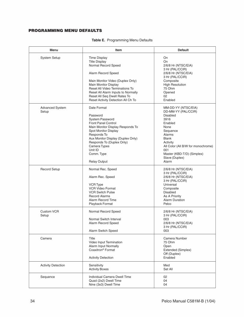
PROGRAMMING MENU DEFAULTS
Table E. Programming Menu Defaults
Menu Item Default
System Setup Time Display OnTitle Display OnNormal Record Speed 2/6/8 Hr (NTSC/EIA)
3 Hr (PAL/CCIR)Alarm Record Speed 2/6/8 Hr (NTSC/EIA)
3 Hr (PAL/CCIR)Main Monitor Video (Duplex Only) CompositeMain Monitor Display High ResolutionReset All Video Terminations To 75 OhmReset All Alarm Inputs to Normally OpenedReset All Seq Dwell Rates To 02Reset Activity Detection All Ch To Enabled
Advanced System Date Format MM-DD-YY (NTSC/EIA)Setup DD-MM-YY (PAL/CCIR)
Password DisabledSystem Password 3916Front Panel Control EnabledMain Monitor Display Responds To NoneSpot Monitor Display SequenceResponds To AlarmsAux Monitor Display (Duplex Only) BlankResponds To (Duplex Only) ActivityCamera Types All Color (All B/W for monochrome)Unit ID 001Comm. Type Master (KBD-T/D) (Simplex)
Slave (Duplex)Relay Output Alarm
Record Setup Normal Rec. Speed 2/6/8 Hr (NTSC/EIA)3 Hr (PAL/CCIR)
Alarm Rec. Speed 2/6/8 Hr (NTSC/EIA)3 Hr (PAL/CCIR)
VCR Type UniversalVCR Video Format CompositeVCR Switch Pulse DisabledRecord Alarms As A PriorityAlarm Record Time Alarm DurationPlayback Format Pelco
Custom VCR Normal Record Speed 2/6/8 Hr (NTSC/EIA)Setup 3 Hr (PAL/CCIR)
Normal Switch Interval 003Alarm Record Speed 2/6/8 Hr (NTSC/EIA)
3 Hr (PAL/CCIR)Alarm Switch Speed 003
Camera Title Camera NumberVideo Input Termination 75 OhmAlarm Input Normally OpenCoaxitron® Format Extended (Simplex)
Off (Duplex)Activity Detection Enabled
Activity Detection Sensitivity MedActivity Boxes Set All
Sequence Individual Camera Dwell Time 02Quad (2x2) Dwell Time 04Nine (3x3) Dwell Time 04

Pelco Manual C581M-B (1/04) 35
PROGRAMMING A PRESET
1. Press the MAIN or SPOT MONITOR key. The green LED over the MAIN or SPOT keylights. When using the MAIN MONITOR, the SPOT MONITOR DISPLAY menu item inthe Advanced System Setup menu must be set to TRACK MAIN (refer to theAdvanced System Setup section).
2. Select the camera.
Addressing by Multiplexer (Switch 7 OFF)a. On the number pad, press the address number of the multiplexer (1-16 if the
keyboard is connected to a multiplexer; 1-8 if the keyboard is connected to aserver), then press the UNIT key. The LED displays the address.
b. On the number keypad press the number of the camera (1-16), then press theCAM key.
Addressing Consecutively (Switch 7 ON)On the number keypad press the number of the camera, then press the CAMkey. Refer to Table C for camera numbers.
3. Position the camera using the pan/tilt and lens keys.
4. On the number keypad press the number of the preset, then hold down thePRESET key for five seconds.
PROGRAMMING A PATTERN
1. Press the MAIN or SPOT MONITOR key. The green LED over the MAIN or SPOT keylights. When using the MAIN MONITOR, the SPOT MONITOR DISPLAY menu item inthe Advanced System Setup menu must be set to TRACK MAIN (refer to theAdvanced System Setup section).
2. Select the camera.
Addressing by Multiplexer (Switch 7 OFF)a. On the number pad, press the address number of the multiplexer (1-16 if the
keyboard is connected to a multiplexer; 1-8 if the keyboard is connected to aserver), then press the UNIT key. The LED displays the address.
b. On the number keypad press the number of the camera (1-16), then press theCAM key.
Addressing Consecutively (Switch 7 ON)On the number keypad press the number of the camera, then press the CAM key.Refer to Table C for camera numbers.
3. On the number pad, press a number key for the pattern number. Example: If you areprogramming pattern 1 press the number 1 key. Then hold down the PATTERN keyuntil the message PROGRAMMING PATTERN appears on the screen.
4. Move the camera through the pattern using the pan/tilt and lens keys.
5. To stop programming the pattern, repress the number key for the pattern followed bythe PATTERN key. Example: Press number 1 and then the PATTERN key if you areprogramming pattern 1. The message PROGRAMMING PATTERN disappears.
NOTE: The LEDs abovethe camera buttons on themultiplexer will illuminate toindicate which cameras arebeing displayed.
NOTE: Refer to your domeor pan and tilt systemmanual for information onthe number of availablepatterns and patterndurations.
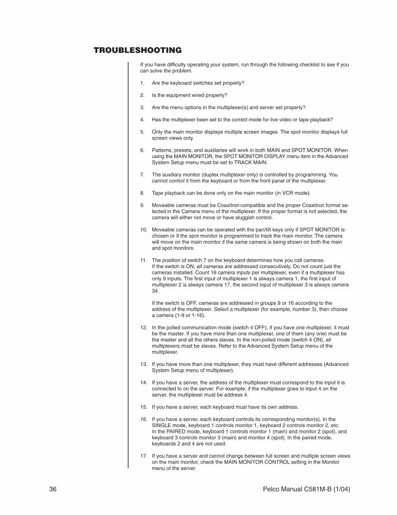
36 Pelco Manual C581M-B (1/04)
TROUBLESHOOTING
If you have difficulty operating your system, run through the following checklist to see if youcan solve the problem.
1. Are the keyboard switches set properly?
2. Is the equipment wired properly?
3. Are the menu options in the multiplexer(s) and server set properly?
4. Has the multiplexer been set to the correct mode for live video or tape playback?
5. Only the main monitor displays multiple screen images. The spot monitor displays fullscreen views only.
6. Patterns, presets, and auxiliaries will work in both MAIN and SPOT MONITOR. Whenusing the MAIN MONITOR, the SPOT MONITOR DISPLAY menu item in the AdvancedSystem Setup menu must be set to TRACK MAIN.
7. The auxiliary monitor (duplex multiplexer only) is controlled by programming. Youcannot control it from the keyboard or from the front panel of the multiplexer.
8. Tape playback can be done only on the main monitor (in VCR mode).
9. Moveable cameras must be Coaxitron compatible and the proper Coaxitron format se-lected in the Camera menu of the multiplexer. If the proper format is not selected, thecamera will either not move or have sluggish control.
10. Moveable cameras can be operated with the pan/tilt keys only if SPOT MONITOR ischosen or if the spot monitor is programmed to track the main monitor. The camerawill move on the main monitor if the same camera is being shown on both the mainand spot monitors.
11. The position of switch 7 on the keyboard determines how you call cameras.If the switch is ON, all cameras are addressed consecutively. Do not count just thecameras installed. Count 16 camera inputs per multiplexer, even if a multiplexer hasonly 9 inputs. The first input of multiplexer 1 is always camera 1, the first input ofmultiplexer 2 is always camera 17, the second input of multiplexer 3 is always camera34.
If the switch is OFF, cameras are addressed in groups 9 or 16 according to theaddress of the multiplexer. Select a multiplexer (for example, number 3), then choosea camera (1-9 or 1-16).
12. In the polled communication mode (switch 4 OFF), if you have one multiplexer, it mustbe the master. If you have more than one multiplexer, one of them (any one) must bethe master and all the others slaves. In the non-polled mode (switch 4 ON), allmultiplexers must be slaves. Refer to the Advanced System Setup menu of themultiplexer.
13. If you have more than one multiplexer, they must have different addresses (AdvancedSystem Setup menu of multiplexer).
14. If you have a server, the address of the multiplexer must correspond to the input it isconnected to on the server. For example, if the multiplexer goes to input 4 on theserver, the multiplexer must be address 4.
15. If you have a server, each keyboard must have its own address.
16. If you have a server, each keyboard controls its corresponding monitor(s). In theSINGLE mode, keyboard 1 controls monitor 1, keyboard 2 controls monitor 2, etc.In the PAIRED mode, keyboard 1 controls monitor 1 (main) and monitor 2 (spot), andkeyboard 3 controls monitor 3 (main) and monitor 4 (spot). In the paired mode,keyboards 2 and 4 are not used.
17. If you have a server and cannot change between full screen and multiple screen viewson the main monitor, check the MAIN MONITOR CONTROL setting in the Monitormenu of the server.

Pelco Manual C581M-B (1/04) 37
18. If the UNIT ID, in the ADVANCED SYSTEM SETUP menu, is inadvertently changed atthe keyboard resulting in an uncontrollable sequencing of unit ID numbers and loss ofkeyboard control:
a. Go to the multiplexer and press the down arrow button. The sequencing shouldstop. Exit the menu, then return to the ADVANCED SYSTEM SETUP menu andchange the UNIT ID back to 001. Continue normal programming from the key-board.
OR
b. If the multiplexer is remotely located away from the keyboard, wait until thenumbers sequence to the correct multiplexer unit ID number and immediatelypress any pan/tilt key. The sequencing should stop. Continue normal program-ming from the keyboard.
SPECIFICATIONS
ELECTRICAL
Input Voltage: 12 VAC or ±12 VDC
Power Consumption: 5 watts
KEYBOARD COMMUNICATION
Keyboard Interface: RS-485 (25-foot flat cable supplied)
Connector Type: RJ-45 8-pin modular (female)
MECHANICAL
Keyboard Keypad: Mechanical
Digital Display: Two red seven-segment LEDs
Main/SpotMonitor Indicators: Two green LEDs
GENERAL
Ambient OperatingTemperature: 20° to 120°F (-7° to 49°C)
Humidity: 10% - 90% non-condensing
Dimensions: 8.125 (W) x 7.125 (L) x 2.25 (H) inches (20.64 x 18.10 x 5.72 cm)
Weight: 2.1 lb (0.97 kg)
Shipping Weight: 3 lb (1.35 kg)
Design and product specifications subject to change without notice.

38 Pelco Manual C581M-B (1/04)

Pelco Manual C581M-B (1/04) 39
REVISION HISTORYManual # Date CommentsC581M 8/99 Original version.C581M-A 9/03 Added Regulatory Notices section and changed power specification.C581M-B 1/04 Revised per ECO #03-9291, software upgrade to increase the number of programmable patterns.
Pelco, the Pelco Logo, Camclosure, Coaxitron, Esprit, Genex, Intercept, Legacy, and Spectra are registered trademarks of Pelco. © Copyright 2004, Pelco. All rights reserved.Endura and ExSite are trademarks of Pelco.
This equipment contains electrical or electronic components that must be recycled properly to comply with Directive 2002/96/EC of the European Union regarding the disposal of waste electrical and electronic equipment (WEEE). Contact your local dealer for procedures for recycling this equipment.
PRODUCT WARRANTY AND RETURN INFORMATION
WARRANTYPelco will repair or replace, without charge, any merchandise proved defective in material orworkmanship for a period of one year after the date of shipment.
Exceptions to this warranty are as noted below:
• Five years on FT/FR8000 Series fiber optic products.
• Three years on Genex® Series products (multiplexers, server, and keyboard).
• Three years on Camclosure® and fixed camera models, except the CC3701H-2,CC3701H-2X, CC3751H-2, CC3651H-2X, MC3651H-2, and MC3651H-2X camera models,which have a five-year warranty.
• Two years on standard motorized or fixed focal length lenses.
• Two years on Legacy®, CM6700/CM6800/CM9700 Series matrix, and DF5/DF8 Seriesfixed dome products.
• Two years on Spectra®, Esprit®, ExSite™, and PS20 scanners, including when used incontinuous motion applications.
• Two years on Esprit® and WW5700 Series window wiper (excluding wiper blades).
• Eighteen months on DX Series digital video recorders, NVR300 Series network videorecorders, and Endura™ Series distributed network-based video products.
• One year (except video heads) on video cassette recorders (VCRs). Video heads will becovered for a period of six months.
• Six months on all pan and tilts, scanners or preset lenses used in continuous motionapplications (that is, preset scan, tour and auto scan modes).
Pelco will warrant all replacement parts and repairs for 90 days from the date of Pelcoshipment. All goods requiring warranty repair shall be sent freight prepaid to Pelco, Clovis,California. Repairs made necessary by reason of misuse, alteration, normal wear, or accidentare not covered under this warranty.
Pelco assumes no risk and shall be subject to no liability for damages or loss resulting fromthe specific use or application made of the Products. Pelco’s liability for any claim, whetherbased on breach of contract, negligence, infringement of any rights of any party or productliability, relating to the Products shall not exceed the price paid by the Dealer to Pelco forsuch Products. In no event will Pelco be liable for any special, incidental or consequentialdamages (including loss of use, loss of profit and claims of third parties) however caused,whether by the negligence of Pelco or otherwise.
The above warranty provides the Dealer with specific legal rights. The Dealer may also haveadditional rights, which are subject to variation from state to state.
If a warranty repair is required, the Dealer must contact Pelco at (800) 289-9100 or(559) 292-1981 to obtain a Repair Authorization number (RA), and provide the followinginformation:1. Model and serial number2. Date of shipment, P.O. number, Sales Order number, or Pelco invoice number3. Details of the defect or problem
If there is a dispute regarding the warranty of a product which does not fall under thewarranty conditions stated above, please include a written explanation with the productwhen returned.
Method of return shipment shall be the same or equal to the method by which the item wasreceived by Pelco.
RETURNSIn order to expedite parts returned to the factory for repair or credit, please call the factory at(800) 289-9100 or (559) 292-1981 to obtain an authorization number (CA number if returnedfor credit, and RA number if returned for repair).
All merchandise returned for credit may be subject to a 20% restocking and refurbishingcharge.
Goods returned for repair or credit should be clearly identified with the assigned CA or RAnumber and freight should be prepaid. Ship to the appropriate address below.
If you are located within the continental U.S., Alaska, Hawaii or Puerto Rico, send goods to:Service DepartmentPelco3500 Pelco WayClovis, CA 93612-5699
If you are located outside the continental U.S., Alaska, Hawaii or Puerto Rico and areinstructed to return goods to the USA, you may do one of the following:
If the goods are to be sent by a COURIER SERVICE, send the goods to:Pelco3500 Pelco WayClovis, CA 93612-5699 USA
If the goods are to be sent by a FREIGHT FORWARDER, send the goods to:Pelco c/o Expeditors473 Eccles AvenueSouth San Francisco, CA 94080 USAPhone: 650-737-1700Fax: 650-737-0933

Worldwide Headquarters3500 Pelco Way
Clovis, California 93612 USA
USA & CanadaTel: 800/289-9100Fax: 800/289-9150
InternationalTel: 1-559/292-1981Fax: 1-559/348-1120
www.pelco.com
ISO9001
United States | Canada | United Kingdom | The Netherlands | Singapore | Spain | Scandinavia | France | Middle East