pdst solidworks 2015 - t4 spring/seminars/dcg...dcg - wireless mouse page 2 wireless mouse...
TRANSCRIPT

Wireless Mouse
Surfaces
Design & Communication Graphics

DCG - Wireless Mouse Page 1
Table of Contents
Table of Contents ....................................................................................................................... 1
Introduction …………………………………………………………………………………………………………………………2
Mouse Body….………………………………………………………………………………………………………………………3
Edge Cut …………………………………………………………………………………………………………………………….12
Centre Cut..………………………………………………………………………………………………………………………..14
Wheel Opening………………………………………………………………………………..…………………………………15
Wheel Location…………………………………………………………………………………………………..………………16
Laser…..………………………………………………………………………………………………………………………………18
Wheel…………………………………………………………………………………………………………………………………18
Mouse Mat………………………………………………………………………………………..……………………………….20
Assembly…………………………………………………………………………………………………………………………….21

DCG - Wireless Mouse Page 2
Wireless Mouse
Introduction Surface modelling is clearly a lot more work than solid modelling. Surface modelling
forces you to work face by face and faces must fit together. These action are all performed automatically in solid modelling. Where Surface techniques become beneficial is in a situations where solid modelling become clumsy or inefficient, or when a given modelling task is simply impossible with solids. The focus of this exercise is to add to the skills based on the advanced surface modelling materials and explore further the functionality of surfacing tools.
Learning Intentions
In addition to the normal command the following commands will be used.
o Splines o Projected Curves o Lofted Surfaces o Filled Surfaces o Knit Surfaces o 3D Sketch Convert Entity o Create Solid o Dome

DCG - Wireless Mouse Page 3
Mouse Body
The part is symmetrical with respect to the Right reference
plane. Open a new part and name it Mouse. Select the Top
reference plane and sketch a rectangle as shown. Exit the sketch
and rename the sketch Reference Dim. This sketch will help you
sketch the free-form splines approximately the correct size.
Bottom Edge
Open a new sketch on the Top reference plane, and sketch a
5-point spline as shown to represent the bottom edge of the
mouse. Draw only half of the outline. Make sure that the
endpoints of the spline are Coincident with the corners of the
rectangle in the Reference Dim sketch.

DCG - Wireless Mouse Page 4
Add Relations
Use relations on the handles at the ends of the spline to create tangency across the
line of symmetry. Add Horizontal relations to the Spline handles
Tangent Relation
To make the spline tangent to the rectangle, sketch a short construction line Tangent
to the spline itself, not to a handle or a spline point. Add a Vertical relation to the
construction line. Make the Endpoint of the construction line Coincident with the
rectangle.
DCG - Wireless Mouse Page 5
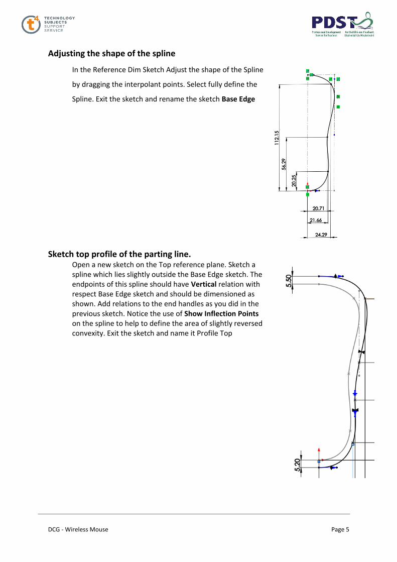
Adjusting the shape of the spline
In the Reference Dim Sketch Adjust the shape of the Spline
by dragging the interpolant points. Select fully define the
Spline. Exit the sketch and rename the sketch Base Edge
Sketch top profile of the parting line.
Open a new sketch on the Top reference plane. Sketch a spline which lies slightly outside the Base Edge sketch. The endpoints of this spline should have Vertical relation with respect Base Edge sketch and should be dimensioned as shown. Add relations to the end handles as you did in the previous sketch. Notice the use of Show Inflection Points on the spline to help to define the area of slightly reversed convexity. Exit the sketch and name it Profile Top
DCG - Wireless Mouse Page 6
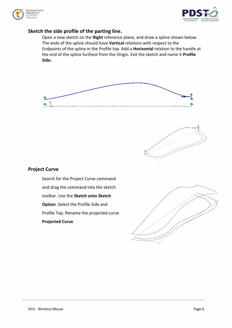
Sketch the side profile of the parting line. Open a new sketch on the Right reference plane, and draw a spline shown below. The ends of the spline should have Vertical relations with respect to the Endpoints of the spline in the Profile top. Add a Horizontal relation to the handle at the end of the spline furthest from the Origin. Exit the sketch and name it Profile Side.
Project Curve
Search for the Project Curve command
and drag the command into the sketch
toolbar. Use the Sketch onto Sketch
Option. Select the Profile Side and
Profile Top. Rename the projected curve
Projected Curve
DCG - Wireless Mouse Page 7
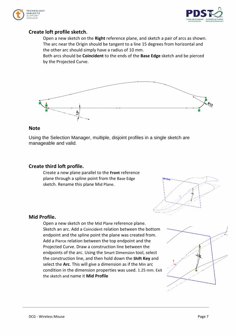
Create loft profile sketch.
Open a new sketch on the Right reference plane, and sketch a pair of arcs as shown. The arc near the Origin should be tangent to a line 15 degrees from horizontal and the other arc should simply have a radius of 10 mm. Both arcs should be Coincident to the ends of the Base Edge sketch and be pierced by the Projected Curve.
Note
Using the Selection Manager, multiple, disjoint profiles in a single sketch are manageable and valid.
Create third loft profile. Create a new plane parallel to the Front reference plane through a spline point from the Base Edge sketch. Rename this plane Mid Plane.
Mid Profile. Open a new sketch on the Mid Plane reference plane. Sketch an arc. Add a Coincident relation between the bottom endpoint and the spline point the plane was created from. Add a Pierce relation between the top endpoint and the Projected Curve. Draw a construction line between the endpoints of the arc. Using the Smart Dimension tool, select the construction line, and then hold down the Shift Key and select the Arc. This will give a dimension as if the Min arc condition in the dimension properties was used. 1.25 mm. Exit
the sketch and name it Mid Profile

DCG - Wireless Mouse Page 8
Create the Surface Loft. Use the Selection Manager to select open profiles at the ends. The Mid Profile sketch will not require the Selection Manager. For Guide Curves, select Projected Curve and Bottom Edge Edge. For Start/End Constraints, use Normal to Profile for both ends so that it is smooth across the plane of symmetry.
DCG - Wireless Mouse Page 9
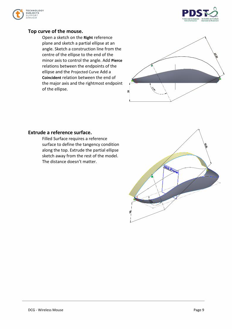
Top curve of the mouse. Open a sketch on the Right reference plane and sketch a partial ellipse at an angle. Sketch a construction line from the centre of the ellipse to the end of the minor axis to control the angle. Add Pierce relations between the endpoints of the ellipse and the Projected Curve Add a Coincident relation between the end of the major axis and the rightmost endpoint of the ellipse.
Extrude a reference surface.
Filled Surface requires a reference surface to define the tangency condition along the top. Extrude the partial ellipse sketch away from the rest of the model. The distance doesn’t matter.

DCG - Wireless Mouse Page 10
Filled surface Click the Filled Surface. Select the Edge of the extruded surface and the edge of the lofted surface. Use the end condition Tangent for the extruded surface and Contact for the lofted surface. Notice that with Optimize surface selected, the surface again becomes degenerate. This is because the Optimize surface option applies a simplified surface patch that is similar to a lofted surface. Clear Optimize surface and you will get a better, four-sided patch. Click OK.
Hide the Extruded Surface

DCG - Wireless Mouse Page 11
Mirror the surface bodies. Click Mirror on the Features toolbar. Select the Right reference plane as the mirror plane. In the Bodies to Mirror selection list, select the lofted and filled surfaces to be mirrored Uncheck Knit surfaces. Leaving the Knit surfaces option cleared this way there is no confusion about what will or will not knit by the Mirror feature
Planar surface. Select the edges of the lofted surface and mirrored loft on the bottom and create a planar surface.
Knit
Knit the five surface bodies into a solid Save the Part Select
Try to form Solid
DCG - Wireless Mouse Page 12
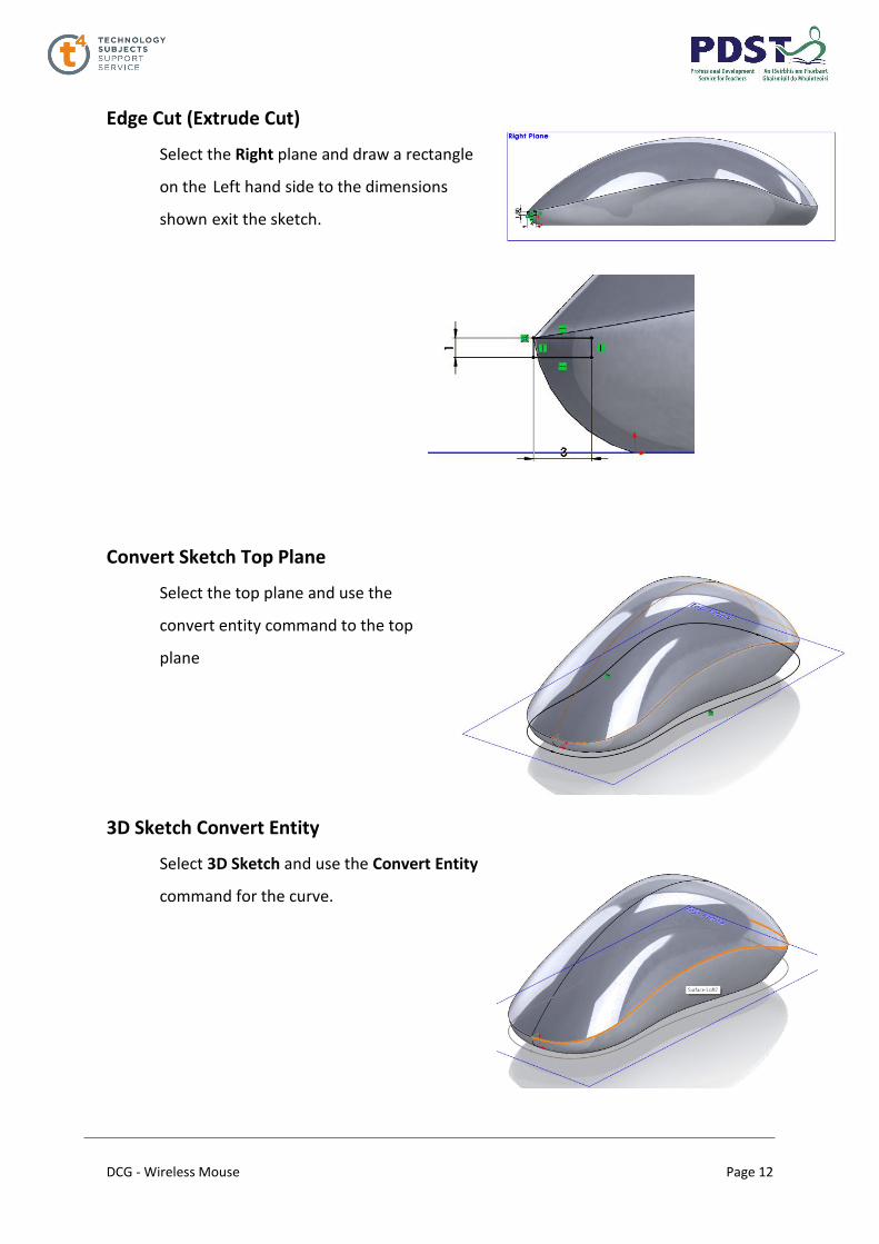
Edge Cut (Extrude Cut)
Select the Right plane and draw a rectangle
on the Left hand side to the dimensions
shown exit the sketch.
Convert Sketch Top Plane
Select the top plane and use the
convert entity command to the top
plane
3D Sketch Convert Entity
Select 3D Sketch and use the Convert Entity
command for the curve.

DCG - Wireless Mouse Page 13
Edge Cut
Select the Swept Cut command Select the
Profile Path and Guide Curve

DCG - Wireless Mouse Page 14
Centre Cut
Select the Right plane and
use the Convert Entity
sketch command and trim
the line to the dimension
shown.
Note: A vertical construction line at the centre.
Use the Section View command to assist in the create the centre line
Create a Plane on the end of the trimmed sketch.
Sketch a square to the dimensions shown
Select the Swept Cut to create the mid Centre Cut

DCG - Wireless Mouse Page 15
Wheel Opening
Select the Right plane and create sketch
to the dimensions shown
Plane Creation
Create a plane at the end of the
construction line
Straight Slot
Use the Straight Slot command to create a sketch to the dimension shown and
Extrude 21mm

DCG - Wireless Mouse Page 16
Fillet 5mm
Create a fillet 5mm
Wheel Location
Select the Right plane and reference the
Midpoint of the wheel slot create a line 12.5mm and a
circle radius 2mm. Use the Extrude Cut command and
select midpoint extrude distance of 14 mm
DCG - Wireless Mouse Page 17
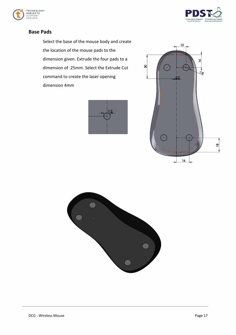
Base Pads
Select the base of the mouse body and create
the location of the mouse pads to the
dimension given. Extrude the four pads to a
dimension of .25mm. Select the Extrude Cut
command to create the laser opening
dimension 4mm

DCG - Wireless Mouse Page 18
Laser (New Part)
Sketch a circle of 2mm radius extrude to a distance of
1mm. Use the Dome command to create the top of the
laser
Wheel Hub (New Part)
Create the sketch to the dimensions below and revolve to create the
wheel hub. Create a circle of 2mm on the mid plane and use the
Mid Plane End Condition to a distance of 14mm
DCG - Wireless Mouse Page 19
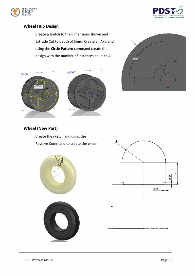
Wheel Hub Design
Create a sketch to the dimensions shown and
Extrude Cut to depth of 5mm. Create an Axis and
using the Circle Pattern command create the
design with the number of instances equal to 4.
Wheel (New Part)
Create the sketch and using the
Revolve Command to create the wheel

DCG - Wireless Mouse Page 20
Mouse Mat
Create a rectangle 200mm by 160 mm and
Extrude to a distance of 5mm and fillet the
edges. Apply Decals to the mouse mat.
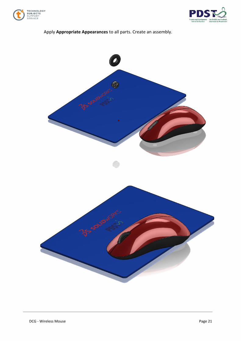
Assembly
DCG - Wireless Mouse Page 21
Apply Appropriate Appearances to all parts. Create an assembly.