w.r. grace & co., inc. (acton plant), landfill … indicator light for the high/high level alarm...
TRANSCRIPT
Superfund Records Center . SDMS DocID 508277
SITE: W , $ CfTA** BREAK: %\p OTHER: S O O T l
LANDFILL AREA
GROUNDWATER OPERATION & MAINTENANCE PLAN
W.R. GRACE SUPERFUND SITE
ACTON, MASSACHUSETTS
PREPARED FOR
W.R. GRACE & Co. - CONN
62 WHITTEMORE AVENUE
CAMBRIDGE, MASSACHUSETTS 02140
PREPARED BY
O & M, INC.
450 MONTBROOK LANE
KNOXVILLE,TN 37919
AND
TETRA TECH GEO
ONE MONARCH DRIVE, SUITE 101
LITTLETON, MA 01460
APRIL, 2012
REVISION 01
Disclaimer: This document is a DRAFT document prepared by W. R. Grace under a government Consent Decree. This document has not undergone formal review by EPA and Massachusetts Department of Environmental Protection. The opinions, findings, and conclusions, expressed are those of the author and not those of USEPA and MassDEP.
O&M Inc./Tetra Tech GEO

¥ PAGE
1.0 INTRODUCTION 1 1.1 ELEMENTS OF THE O & M PLAN 1
1.2 IMPORTANT MESSAGES AND WARNINGS 1
2.0 EQUIPMENT DESCRIPTION 3 2.1 TREATMENT SYSTEM INFLUENT CONTAMINANTS OF CONCERN 3
2.2 EXISTING EXTRACTION WELLS 3
2.3 GROUNDWATER TREATMENT SYSTEM , 3
2.3.1 TREATMENT SYSTEM BUILDING 4
2.3.2 METALS MICROFILTRATION SYSTEM 4
2.3.3 PHOTOCATALYTIC OXIDATION SYSTEM .„ 10
2.3.4 DISCHARGE EQUALIZATION TANK AND PIPING 11
2.3.5 ANCILLARY SYSTEMS 11
3.0 SYSTEM OPERATION 14 3.1 START-UP PROCEDURE 14
3.2 NORMAL OPERATING CONDITIONS 14
3.3 NORMAL SHUT-DOWN PROCEDURE 15
3.3.1 LOCAL SHUTDOWN 15
3.4 EMERGENCY SHUT-DOWN PROCEDURE 15
4.0 SYSTEM MAINTENANCE 16 4.1 GENERAL MAINTENANCE 16
4.1.1 RESIDUALS MANAGEMENT ; 18
4.2 MAJOR MAINTENANCE 18
4.3 SPARE PARTS... 19
4.4 WINTERIZATION 19
5.0 MONITORING, SAMPLING AND REPORTING 20 5.1 LONG-TERM MONITORING 20
5.2 REPORTING 23
6.0 POTENTIAL OPERATING PROBLEMS AND CORRECTIVE ACTIONS 25 6.1 EQUIPMENT MALFUNCTIONS ..: 25
6.2 EXCEEDANCE OF A GROUNDWATER DISCHARGE STANDARD 25
6.3 DECLINING YIELD OF EXTRACTION WELLS 28 7.0 DOCUMENTATION 31
7.1 OPERATING REPORTS '. 31
7.2 MAINTENANCE RECORDS 34
7.3 NON-ROUTINE CONDITIONS 34
7.4 PERSONNEL RECORDS 34
8.0 SAFETY ISSUES 35 8.1 GENERAL SITE SAFETY 35
9.0 REFERENCES 38
(Revision 01) O & M, Inc./Tetra Tech GEO
*
TABLES
PAGE
TABLE 3-1TABLE 4-1
TABLE 4-3
TABLE 5-1
TABLE 6-1
TABLE 6-2
'
GWTS DESIGN OPERATING CONDITIONS
SUMMARY OF ROUTINE MAINTENANCE •.
CONTACT INFORMATION FOR EQUIPMENT MANUFACTURERS/SUPPLIERS
MONITORING AND SAMPLING FOR LANDFILL AREA REMEDIAL ACTION
POTENTIAL OPERATIONAL PROBLEMS AND REMEDIES
JUNE 2010 EXTRACTION RATES AND SPECIFIC CAPACITIES
15 17
18
22
27
29
TABLE 6-3 STEPS TO DETERMINE CAUSE AND CORRECT LOSS OF EXTRACTION WELL YIELD 30
TABLE 7-1
TABLE 8-1
MONTHLY GWTS INSPECTION REPORT AND EXTRACTION WELL MONITORING
REPORT 32
HAZARDS ASSOCIATED WITH GWTS OPERATION 37
FIGURES
FIGURE 2-1 TREATMENT SYSTEM LOCATION
FIGURE 2-2 PROCESS FLOW DIAGRAM
FIGURE 2-3 EQUIPMENT & BUILDING LAYOUT
APPENDICES
APPENDIX A GROUNDWATER TREATMENT SYSTEM AS-BUILT DESIGN DRAWINGS
APPENDIX B SIEMENS WASTEWATER TREATMENT SYSTEM O&M MANUAL
APPENDIX C SIEMENS J-PRESS FILTER PRESS OWNERS MANUAL
APPENDIX D KAISER AIR COMPRESSORS MANUAL
APPENDIX E PURIFICS PHOTO-CAT MANUAL
APPENDIX F ADDENDUM TO THE QUALITY ASSURANCE PROJECT PLAN
APPENDIX G SITE SPECIFIC HEALTH AND SAFETY PLAN
(Revision 01) O & M, Inc./Tetra Tech GEO
4 1.0 I N T R O D U C T I O N
The Landfill Area Groundwater Operation & Maintenance Plan (O&M Plan) for the W. R. Grace & Co. - Conn. (Grace) Acton Superfund Site (the Site) is submitted in accordance with the Operable Unit Three (OU-3) Remedial Design/Remedial Action (RD/RA) Statement of Work (SOW), as approved by the United States Environmental Protection Agency (USEPA) and the Massachusetts Department of Environmental Protection (MassDEP) on August 30, 2006 (USEPA, 2006).
This O&M Plan provides a general description of the equipment and operating procedures for the Ground Water Treatment System (GWTS) located in the Landfill Area of the Site. The GWTS is designed to remove organics and metals from a flow rate up to approximately 100 gallons per minute (gpm) of extracted ground water and discharge the treated water into Sinking Pond.
Details on the site background and design are presented in previous documents, including the Landfill Area Groundwater Final Design (GeoTrans, 2010b).
The major components of the GWTS include a treatment system building, metals microfiltration system, photocatalytic oxidation system, discharge equalization tank and piping system, and ancillary systems.
1.1 ELEMENTS OF THE O&M PLAN
The O&M Plan is comprised of the following elements:
Equipment Description
System Operations
System Maintenance
Monitoring and Sampling
Potential Operating Problems and Remedies
Documentation and Reporting
Safety Issues
Each of the elements is discussed in detail in Sections 2.0 through 8.0, respectively.
1.2 IMPORTANT MESSAGES AND WARNINGS
This manual should be in the possession of the personnel who operate and maintain the GWTS. The purpose of this manual is to instruct and advise operators and maintenance personnel. This manual will remain a valuable resource for the safe, economical, efficient operation and maintenance of the GWTS.
1 (Revision 01) O & M, Inc./Tetra Tech GEO

Safety is a key consideration of this O&M Workplan. Only qualified personnel who have been properly instructed in this equipment's proper operation and maintenance requirements and in its potential hazards shall be allowed to operate and maintain it.
(Revision 01) O&M, Inc./Tetra Tech GEO
<
2.0 EQUIPMENT DESCRIPTION
2.1 TREATMENT SYSTEM INFLUENT CONTAMINANTS OF CONCERN
The Landfill Area groundwater remedy groundwater treatment system (GWTS) was designed to extract contaminated groundwater located immediately southeast and southwest of the Industrial Landfill. The groundwater treatment system has been designed to remove the maximum VOC, 1,4-dioxane, arsenic, iron, manganese and phosphorus concentrations to below discharge standards.
2.2 EXISTING EXTRACTION WELLS
The system consists of five (5) extraction wells (SELF-1, SELF-2, SWLF-1, MLF, and WLF). Each well is outfitted with an electric submersible pump that is compatible with the identified contaminants.
Each extraction well pump discharges individually into a single 550-gallon, polyethylene, enclosed dome top equalization tank housed in an 8-foot by 20-foot steel shipping container located southwest of the Industrial Landfill (Figure 2-1). The purpose of the equalization tank system is to allow control of the groundwater flow rate to the GWTS. Each extraction well discharge line is outfitted with a pressure gauge, flow control/isolation valve, flow meter/totalizer and sample port.
The motor starter and on/off controls for each extraction pump are installed on the wall near the system control panel. The equalization tank is outfitted with level controls to operate a transfer pump. In addition, a high/high level alarm is installed to stop the extraction well pumps in the event of a unit operation failure.
The system has one centralized control panel. The control panel has an alarm/shutdown indicator light for the high/high level alarm in the equalization tank and an emergency shut off switch. The current equalization tank system is incorporated into the new GWTS.
2.3 GROUNDWATER TREATMENT SYSTEM
The new GWTS is modular and consists of two (2) main treatment unit operations; metals removal and VOC removal. The treatment system components, which are described further below, include:
Treatment System Building; Metals Microfiltration System; Photocatalytic Oxidation System; Discharge Equalization Tank and Piping; and Ancillary Systems.
(Revision 01) O & M , Inc./Tetra Tech GEO
y As built design drawings for the GWTS are included in Appendix A. Manuals for the main components of the GWTS are included as Appendices B through E.
2.3.1 TREATMENT SYSTEM BUILDING
Water from the extraction wells is piped underground to the existing equalization tank system. The extracted groundwater is then pumped to the new treatment system building for treatment by the GWTS prior to discharge to Sinking Pond. The new building is a 50-foot by 100-foot metal building with a roof height of 25 feet. The floor is constructed of reinforced coated concrete and incorporates a containment berm around the entire perimeter and select pieces of equipment. Figure 2-1 shows the location of the new treatment building, as well as the piping from the existing equalization tank system to the new building and from the new building to Sinking Pond. Figure 2-2 shows the process flow diagram and Figure 2-3 shows the equipment and building layout.
2.3.2 METALS MICROFILTRATION SYSTEM
The Siemens metals microfiltration system is designed to remove arsenic, iron, manganese and phosphorus from Site groundwater to below discharge limits.
The Siemens metals microfiltration system consists of the following main components:
Inlet Equalization Tank and Transfer Pump; Dual Chemical Reaction System; Membrane Microfiltration System with Semi-Automatic Cleaning System; Effluent Neutralization System; Sludge Storage/Thickening Tank; Filter Press System; Filtrate Collection/Transfer Tank/Transfer Pump; Liquid Chemical Addition System; Powdered Chemical Addition System; and Chemical Storage Totes.
The Siemens membrane microfiltration system is described further below.
(Revision 01) O&M, Inc./Tetra Tech GEO
Inlet Equalization Tank and Transfer Pump The inlet equalization tank is a 12,000-gallon molded high-density polyethylene tank with an enclosed dome top. The duplex transfer pump system is a skid-mounted, piped and wired module designed to transfer wastewater from the inlet equalization tank to the first stage of the dual chemical reaction system. Included are two horizontal centrifugal pumps, flow and pressure indicators, isolation valves and piping manifold. A manually adjustable diaphragm throttling valve, in coordination with the flow indicator, is used to ensure proper flow delivery. The system design provides for one pump online and a second pump as a standby alternate pump. Level controls are wired into the. overall control system that manages the on/off functions of the online pump. Manual on/off functions are also provided. A check valve on the discharge of the pump prevents siphoning. Components include:
12,000-gallon capacity, HDPE, dome top tank; Man way; Pump suction connection; Duplex, horizontal centrifugal pumps; 100 gpm capacity at 50 feet total discharge head; 460-VAC, 3-phase, TEFC motors; Pump discharge flow meter; Pump discharge pressure gauge; Ultrasonic level control for pump on/off control; and Pump skid with Schedule-80 PVC piping and shutoff valves.
Dual Chemical Reaction System
This is a two stage chemical mixing and reaction system consisting of two chemical mixing modules that are piped, wired and designed as a single operating module. Each module includes HDPE reaction tanks (with hinged covers) mounted under a steel access catwalk. The steel access structure is coated for maximum corrosion protection. The catwalk grating is constructed of fiberglass reinforced plastic (FRP).
In the first reaction tank (pre-treatment step), the wastewater pH is adjusted (if necessary). The first stage module is equipped with an electric mixer, duplex pH sensors, and duplex ORP sensors. Sodium hypochlorite (oxidant) is added volumetrically to optimize the iron and arsenic removal. Sodium hydroxide is added volumetrically to adjust the pH to maintain optimum removal of manganese. This is typically between an 8 to 8.2 pH. A 10-minute
(Revision 01) 5 O&M, Inc./Tetra Tech GEO
reaction time is maintained.
The wastewater flows via gravity to the second reaction tank. This is the solids formation stage. This compartment is equipped with an electric mixer and duplex pH sensor similar to the first reaction stage of the system. The pH is adjusted by addition of sodium hydroxide to precipitate the manganese. A 10-minute reaction time is maintained.
By this stage of the process, the inorganic contaminants of interest have been converted to filterable solids. Both reaction tank modules are piped, wired and equipped with instrumentation and chemical injection metering pumps. The mixers, chemical pumps and instrumentation are wired into the overall system Programmable Logic Controller (PLC). The chemical reaction system is contained in a secondary containment structure capable of holding 110% of the capacity of the system. Components include:
• Two 1,000-gallon capacity, heavy-duty, HDPE reaction tanks (with hinged covers);
• Two heavy-duty mixers; • Two pH monitor/transmitters with four pH probes; • One ORP monitor/transmitter with two ORP probes in the
first reaction tank; • Five chemical metering pumps; and • Catwalk with stairs for easy access to the equipment.
Membrane Microfiltration System with Semi-Automatic Cleaning System The system operates with wastewater flowing by gravity from the second stage of the dual chemical reaction system into the microfilter concentration tank where solids separation begins. Wastewater from the concentration tank is pumped through the microfiltration membrane modules. The membrane is a polyvinylidene difluoride (PVDF) material that is cast on the inside of a 1-inch polyethylene support tube. Several membranes are bundled into a larger housing to form a membrane module. This technology utilizes cross-flow filtration where the waste slurry is pumped at a high velocity through the center of the membrane tubes and returned back to the concentration tank. The filtered water or permeate passes through the membrane and into
. the effluent neutralization system. Each pass through the membrane concentrates the slurry a little more. To prevent rapid plugging or fouling, the membranes are back-pulsed with air and treated water.
(Revision 01) 6 O&M, Inc./Tetra Tech GEO
The concentration tank is equipped with an ultrasonic level control that allows the microfilter feed pump to cycle on and off. The purpose of this tank is to ensure that a consistent concentration of solids is pumped to and from the microfiltration membranes. Solids dewatering is automatic. The solids are removed from the concentration tank to a sludge storage/thickener tank by an air diaphragm pump. The duration and frequency control of the air diaphragm pump is automatic.
A flow indicator and totalizing meter is provided on the filtrate line. Once the flow drops below a certain rate, a portion of the system must be taken off-line for cleaning. The semi-automatic cleaning system automates the valves associated with the cleaning process and helps to limit operator intervention during the cleaning cycle. The membranes are flushed with system make-up water prior to being placed back in service. The chemical cleaning tank and system make-up water tank, along with a recirculation pump are part of the clean-in-place system. The membrane microfiltration system is contained in a secondary containment structure capable of holding 110% of the capacity of the system. Components include:
• 2,600-gallon capacity, FRP tank with ultrasonic level control; Two 30 HP process recirculation pumps; Two (2) sets of 24, 10-tube membrane filtration modules; Back pulse mechanism; Two permeate flow meters; Semi-automatic cleaning system with cleaning pump; System make-up water flush tank, covered cleaning tank, and automated valves; and
• Air operated double diaphragm pump for solids removal.
Effluent Neutralization System
An effluent neutralization system is provided for any required adjustments to the process stream prior to the Purifies Photo-Cat Photo-Catalytic oxidation system. The effluent neutralization system is sized to receive and treat the effluent from the membrane microfiltration system. The reaction chamber is sized for a minimum 10-minute retention time at the maximum flow rate. The mixer is designed to ensure proper mixing and homogenous treatment. The addition of the Oxone takes place automatically. The effluent leaves the system by gravity. Components include:
• One 2,000-galIon capacity, HDPE dome top tank;
(Revision 01) 7 O & M, Inc./Tetra Tech GEO
• . One heavy-duty mixer; • One pH monitor/transmitter with two pH probes; and • Two chemical metering pumps.
Sludge Storage/Thickening Tank
The sludge thickening tank stores sludge so the filter press can be completely loaded. The sludge from the microfilter concentration tank is pumped to the thickening tank via an air operated diaphragm pump. Once the sludge is in the thickening tank, gravity may further increase the solids concentration. As more sludge is added to the thickening tank, the supernatant gravity flows back to the waste treatment system for reprocessing. The thickened sludge from the bottom of the thickening tank is then pumped to a filter press. The proposed sludge storage/thickening tank includes a mixer to allow for manual addition of a body feed (if required) to allow for better filter press operation. Components include:
3,000-gallon capacity, vertical, cylindrical, Conical bottom FRP tank; Mixer; Overflow nozzle; Ultrasonic level control; Flanged bottom nozzle; Powder feed chute with dust control hood and fan; Scissor lift capable of 96" travel; and Operator access platform with ladder.
Filter Press System
The filter press system consists of an air diaphragm transfer pump system and a filter press. The air diaphragm transfer pump system is a skid-mounted, piped and wired module designed to transfer sludge/slurry from the sludge thickening tank to the filter press. The system includes an air diaphragm pump, isolation valves and piping manifold. The filter press dewaters the slurry of sludge to typically between 20 and 30 percent solids. Components include:
Simplex, air operated diaphragm pump; 50 gpm capacity at 50 feet total discharge head; Pump skid with Schedule-80 PVC piping; 20 cu ft filter cake capacity; 100 psi filtration capacity; Center feed;
(Revision 01) O&M, Inc./Tetra Tech GEO
Four comer filtrate discharge connection; Set of gasketed polypropylene plates; Air blow down manifold; Semi-automatic plate shifter; Painted steel skeleton; and Automatic pump control;
Filtrate Collection/Transfer Tank/Transfer Pump
The filter press filtrate collection/transfer tank is a molded high-density polyethylene tank with an enclosed dome top. The tank is sized to provide sufficient volume for collecting filter press filtrate and sludge thickener decant prior to transferring it back to the inlet equalization tank. A graduated scale is molded onto the side of the tank. Liquid level and volume are typically visible through the wall of the tank. The air diaphragm transfer pump system is a skid-mounted, piped and wired module designed to transfer filter press filtrate from the filtrate collection/transfer tank to the inlet equalization tank for reprocessing through the system. The system includes an air diaphragm pump, isolation valves and piping manifold. The steel frame and platform are coated for corrosion protection. Level controls are wired into the overall control system to manage the on/off functions of the pump. Manual on/off functions are provided. Components include:
One 1,000-gallon capacity, HDPE dome top tank; Man way; Inlet connection; Pump suction connection; Simplex, air operated diaphragm pump; 50 gpm capacity at 50 feet total discharge head; Ultrasonic level control for pump on/off control; and Pump skid with Schedule-80 PVC piping.
Liquid Chemical Addition System
A liquid chemical make-up and delivery system uses liquid feed chemicals (sodium hypochlorite and sodium hydroxide) for controlled and convenient introduction of the reagent into the reaction section of the system. A feed tank is periodically filled with the desired quantity of chemical and is delivered by a metering pump to the reaction tank. Components include:
• Two 300-gallon capacity, heavy-duty, HDPE domed tanks; • Ultrasonic level control for alarm; and • Two chemical metering pumps.
(Revision 01) 9 O & M, Inc./Tetra Tech GEO
Powdered Chemical Addition System
A chemical make-up and delivery system dissolves granular chemical reagent (Oxone) for controlled and convenient introduction of the reagent into the effluent neutralization system. Oxone is being added as an oxidant for use in the Purifies Photo-Cat Photo-Catalytic oxidation system. A tank is periodically filled with the desired quantity of water and granular powdered chemical is added manually in the prescribed amount. A mixer assures that the reagent is completely dissolved before it is delivered by a metering pump to the reaction tank. Components include:
• One 100-gallon capacity, heavy-duty, HDPE covered tank; • Ultrasonic level control for alarm;
One mixer; and One chemical metering pump.
2,3.3 PHOTO-CATALYTIC OXIDATION SYSTEM
The Purifies Photo-Cat photocatalytic oxidation system is designed to remove and destroy dissolved-phase VOCs and 1,4-dioxane from the extracted groundwater. The system consists of the following:
• Photo-Cat Inlet Equalization Tank; and • Photo-Cat Photo Catalytic Oxidation Unit.
Photo-Cat Inlet Equalization Tank
The Photo-Cat inlet equalization tank is a molded high-density polyethylene tank with an enclosed dome top. The tank is sized to provide sufficient volume for collecting groundwater from the effluent neutralization tank. A graduated scale is molded onto the side of the tank. A transfer pump in the Photo-Cat transfers groundwater from the inlet equalization tank to the Photo-Cat system. Components include:
• One 1,000-gallon capacity, HDPE, dome top tank; • Man way; and, • High level shutdown switch.
(Revision 01) 10 O&M, Inc./Tetra Tech GEO
Photo-Cat Photo catalytic Oxidation Unit
A Purifies Photo-Cat photo catalytic oxidation system will remove and destroy dissolved-phase VOCs and 1,4-dioxane from the extracted groundwater. The Photo-Cat is capable of treating a maximum of 60-gpm continuous throughput. The Purifies Photo-Cat model results show that a 3-rack unit will remove VOCs and 1,4-dioxane to below discharge levels. Oxone (oxidant) is added as a liquid solution in the neutralization tank to enhance the treatment efficiency. The Photo-Cat transfer pump transfers the treated groundwater from the Photo-Cat sump into the discharge equalization tank. Components include:
Purifies 30kW unit; 3 rack unit; 460 volt, 3-phase, 100 gpm capacity; Stainless steel housing; Two transfer pumps; and 1 to 100 gpm flow capacity.
2.3.4 DISCHARGE EQUALIZATION TANK AND PIPING
The Photo-Cat system discharges. into a 12,000-gallon capacity, polyethylene, enclosed dome top, discharge equalization tank. The purpose of the discharge equalization tank is to allow control of the groundwater discharge and system make-up water. The tank is outfitted with level controls operating the two (2) transfer pumps. In addition, a high/high level alarm is used to stop the treatment system in the event of a unit operation failure. The discharge equalization tank transfer pumps transfers the treated groundwater from the equalization tank to Sinking Pond and to the system make-up water applications. Components include:
• 12,000-gallon polyethylene, enclosed dome top tank; • Two (2) pumps, 460v, 3-phase, 7.5 hp, TEFC motor; and • 100-gpm flow at 150 feet TDH.
2.3.5 ANCILLARY SYSTEMS
Process Controls
The Siemens Water Technologies standard control system consists of a PLC (Programmable Logic Controller) and HMI (Human Machine Interface) graphical display as the main components providing system automation and operator monitoring of the water treatment system.
(Revision 01) 11 O&M, Inc./Tetra Tech GEO
The HMI display is provided as the central location for an operator to visually monitor equipment status, alarm messaging, and process pH, flow and level values. The adjustment of process set points is performed via the HMI. The HMI allows Hand/Off/Auto (or On/Off) control of devices and display interlock statuses. The HMI also displays all alarm conditions.
The HMI provides the following functionality:
Real-time flow diagram of the system with device status and process values; Ability for the user to "drill down" to get more detail on each module of the system; Hand/Off/Auto or On/Off controls (depending upon device) for all devices (excluding values that stay in Auto for safety reasons); Status of all interlocks for all devices; Current alarm status and historical alarm summary, with button to silence alarm horn and acknowledge alarms; Help text to explain screen operation; For redundant sensors (pH/ORP), a screen for selecting the current device and enabling/disabling differential alarming; Status of all "E-stops" plus a Process Stop button, which stops pumps, but leaves mixers and adjustment chemicals running (for overnight shutdown while keeping particles in suspension); Set point entry with password protection; and Indication when there is a manual override in the system.
There is no overall "System On" button. Instead, each device has its own Hand/Off/Auto controls. This is a safety feature, because there are remote panels that are not in direct view of the HMI.
Air Compressor System
Two (2) 25 HP Kaiser rotary screw air compressor systems are utilized for the plant air supply. The air compressor systems provide approximately 112 standard cubic feet per minute (scfm) of compressed air at 125 pounds per square inch (psi) continuously. Key elements are:
Kaiser Model AS25; 460v, 3-phase, TEFC motor; High efficiency particulate filters; 500 gallon receiver tank; Condensate collection and separation system; and Desiccant air dryer.
(Revision 01) 12 O&M, Inc/Tetra Tech GEO
Process Chemicals Due to' the anticipated small quantities of chemicals required for process operations, the chemicals on-Site will be limited to the quantities required for immediate use in the treatment system operations. These chemicals will be placed next to the specific equipment that require their use and will be located within the containment berms. The following are the chemicals that will be used in the treatment system process:
• Sodium hypochlorite 12.5% (55-gallon container/liquid); • Sodium hydroxide 25% (55-gallon container/liquid); • Oxone (50 pound bags, granular); and, • Citric acid (25 pound bucket, granular).
(Revision 01) 13 O & M, Inc./Tetra Tech GEO

3.0 SYSTEM O P E R A T I O N
Operation of the GWTS is in accordance with manufacturer's recommendations and the procedures outlined in this document. The groundwater treatment system is designed for continuous unattended operation and requires minimal operator assistance. The system has automatic shutdown controls in case of upset conditions.
3.1 START-UP PROCEDURE
Normal startup of the GWTS will be done locally at the control panel within the treatment building.
To perform a normal GWTS startup, follow these steps:
1) Inspect all system components for leaks or other problems; 2) Verify that there is electrical power and no breakers are tripped; 3) Read any alarm conditions noted on the HMI screen; 4) Initiate start-up per:
a) Siemens Wastewater Treatment System Operation and Maintenance Manual, Section 5 (included as Appendix B of this manual),
b) Siemens J-Press Filter Press Owner's Manual 800mm, Section 6 (included as Appendix C of this manual), and
c) Purifies PhotoCat Operation and Maintenance Manual, Section 10 (included as Appendix E of this manual).
3.2 NORMAL OPERATING CONDITIONS
The GWTS will be operated continuously except for short periods of time when it will be temporarily shut off to inspect or repair components and clean the microfiltration unit. Under normal operations, water will be pumped from the ground water extraction wells through the manifold piping and into the GWTS influent equalization tank. The groundwater will be treated by the GWTS in batches then discharged to Sinking Pond. The GWTS design operating conditions are listed in Table 3-1.
(Revision 01) 14 O&M, Inc./Tetra Tech GEO

Table 3-1
GWTS Design Operating Conditions
Parameter Representative Value Comment Average groundwater flow 50 gpm Range 0 - 6 0 gpm rate Average GWTS throughput 60 gpm Range 0 -100 gpm flow rate Sodium hypochlorite addition 25 ml/m rate Sodium hydroxide addition 90 ml/m rate Oxone addition rate 25 mg/1
3.3 NORMAL SHUT-DOWN PROCEDURE
Normal shutdown of the GWTS can be done locally at the control panel within the treatment building.
3.3.1 Local Shutdown
To shut down the system for routine maintenance or any non-emergency reason, follow these steps:
1. Turn off the extraction well pumps through the HMI display at the GWTS control panel. All treatment process equipment will continue to operate until the water level in all equipment reaches minimum levels.
2. If necessary, operating switches for all pumps and equipment can be turned to off once the operator verifies that it is safe to do so.
3. Follow safety procedures before conducting any maintenance activities.
3.4 EMERGENCY SHUT-DOWN PROCEDURE
Although the normal shutdown procedure is the preferred method for shutting down the system, the following procedure will take place when rapid shutdown is necessary during emergency conditions such as fire or catastrophic failure of tanks, pipes, etc:
1. Shut off electrical power to the system by pressing the red "Emergency Stop" button on the GWTS microfiltration unit control panel and the red "Unit Power" button on the Purifies unit control panel.
2. Then shut off electrical power to the system by turning the main disconnect on the southeast wall of the treatment building to the "OFF" position. This will turn off all electricity to the GWTS.
(Revision 01) 15 O&M, Inc./Tetra Tech GEO

4.0 SYSTEM MAINTENANCE
The following sections describe general and component system maintenance, as well as troubleshooting.
4.1 GENERAL MAINTENANCE
General maintenance will be completed in accordance with manufacturer's recommendations. Maintenance inspections will be performed during scheduled monitoring events and as needed throughout the treatment system's operation. Activities include a detailed and thorough examination of the entire groundwater treatment system. All equipment, piping and instrumentation will be inspected with maintenance performed per manufacturer's specifications. The maintenance and troubleshooting guidelines are presented in:
• Section 6 of the Siemens Wastewater Treatment System Operation and Maintenance Manual, (included as Appendix B of this manual);
• Section 7 of the Siemens J-Press Filter Press Owner's Manual, (included as Appendix C of this manual); and
• Section 7 of the Kaiser Air Compressors Manual (included as Appendix D of this manual);
• Section 7 of the Purifies PhotoCat Operation and Maintenance Manual (included as Appendix E of this manual).
Typical maintenance activities include:
Cleaning and redevelopment of the extraction wells and pumps; Cleaning of the flow meters; Checking for leaks in the water and compressed air systems; Lubrication of pump and mixer motors; Visual inspection of UV lamps in Purifies unit; Air compressor oil replacement and air dryer adjustments; Replacement of diaphragms in air operated pumps; and, Hydraulic fluid replacement in the filter press.
System inspections will be done weekly during system operations. Table 4-1 summarizes activities to be performed during routine monitoring and Table 4-2 summarizes the frequency of routine maintenance tasks. Contact information for the manufacturers and vendors of the equipment is presented in Table 4-3. Specific information regarding key maintenance tasks is provided below.
(Revision 01) 16 O&M, Inc./Tetra Tech GEO

Item Extraction Wells
Influent & Discharge Equalization Tanks and Transfer Pumps
Concentration and Filtrate Collection Tanks and Transfer Pumps
Filter Press
Process Monitoring Equipment & Instrumentation
Purifies Photo-Cat Unit
Air Compressors & Dryer
Table 4-1
Summary of Routine Maintenance
Maintenance Activity Check the condition of the well head. Check water level in the extraction well. Record flow and pressure from the extraction well. Check that the flow control valve position is correct for the extraction well. Check that the flow meter is operating properly for the extraction well. Check for leaks in the process piping. Clean pumps and redevelop wells. Check that the water level in the equalization tank is within the normal operating range. Complete manufacturers pump maintenance. Clean flow meters. Check for proper operation of the transfer pumps. Check for leaks. Check that the water level in the tank is within the normal operating range. Check that the level controls are operating properly.
Check wasting rate.
Complete manufacturers pump maintenance.
Check for leaks.
Inspect lines for leaks.
Clean filter plates and cloths to remove particulate build-up.
Check hydraulic fluid level and change fluid yearly.
Inspect hydraulic fluid filters and replace yearly.
Inspect hydraulic cylinder boot for holes or tears.
Check, clean & recalibrate pH and ORP probes.
Check and recalibrate chemical addition pumps. Check for leaks in the process piping. Check inlet filter pressure drop. Annually perform UV output test. Clean titanium dioxide catalyst. Clean cabinet air filters. Check air filter elements and clean or replace as necessary. Check auto drains and clean if necessary. Check compressor oil level and change oil after 6 months of operation. Check condition of desiccant and replace as needed.
Frequency Monthly Weekly Weekly Weekly
Weekly
As required Daily
As required Monthly Daily Daily Daily
Monthly
Monthly
As required
Daily
During use
As needed
As required
As required
Monthly
Weekly
Weekly Daily Weekly As required As needed As needed As needed As needed As required As needed
(Revision 01) 17 O&M, Inc/Tetra Tech GEO
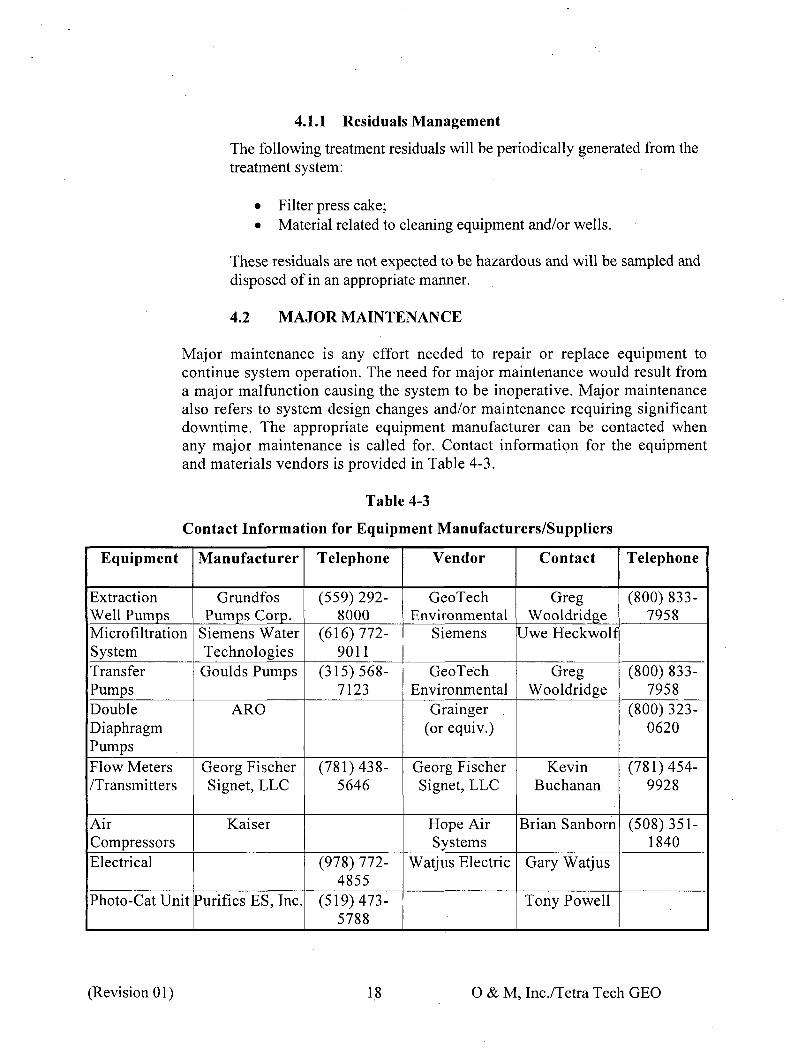
4.1.1 Residuals Management
The following treatment residuals will be periodically generated from the treatment system:
• Filter press cake; • Material related to cleaning equipment and/or wells.
These residuals are not expected to be hazardous and will be sampled and disposed of in an appropriate manner.
4.2 MAJOR MAINTENANCE
Major maintenance is any effort needed to repair or replace equipment to continue system operation. The need for major maintenance would result from a major malfunction causing the system to be inoperative. Major maintenance also refers to system design changes and/or maintenance requiring significant downtime. The appropriate equipment manufacturer can be contacted when any major maintenance is called for. Contact information for the equipment and materials vendors is provided in Table 4-3.
Table 4-3
Contact Information for Equipment Manufacturers/Suppliers
Equipment Manufacturer Telephone Vendor Contact Telephone
Extraction Grundfos (559) 292 GeoTech Greg (800)833Well Pumps Pumps Corp. 8000 Environmental Wooldridge 7958 Microfiltration Siemens Water (616)772 Siemens Uwe Heckwolf System Technologies 9011 Transfer Goulds Pumps (315)568 GeoTech Greg (800)833Pumps 7123 Environmental Wooldridge 7958 Double ARO Grainger (800)323Diaphragm (or equiv.) 0620 Pumps Flow Meters Georg Fischer (781)438 Georg Fischer Kevin (781)454/Transmitters Signet, LLC 5646 Signet, LLC Buchanan 9928
Air Kaiser Hope Air Brian Sanborn (508)351Compressors Systems 1840 Electrical (978)772 Watjus Electric Gary Watjus
4855 Photo-Cat Unit Purifies ES, Inc. (519)473 Tony Powell
5788
(Revision 01) 18 O&M, Inc./Tetra Tech GEO
4.3 SPARE PARTS
A reasonable supply of spare parts will be maintained according to the maintenance requirements for each item of equipment and the vendor recommendations. One (1) pump and motor for each extraction well will be maintained on-site.
4.4 WINTERIZATION
Winter maintenance activities are those required to protect the system from damage during periods of freezing temperatures. The extraction wells are to be inspected prior to the onset of freezing conditions. Snow or heavy ice accumulation will be removed.
(Revision 01) 19 O & M, Inc./Tetra Tech GEO
5.0 M O N I T O R I N G , SAMPLING AND REPORTING
5.1 LONG-TERM MONITORING
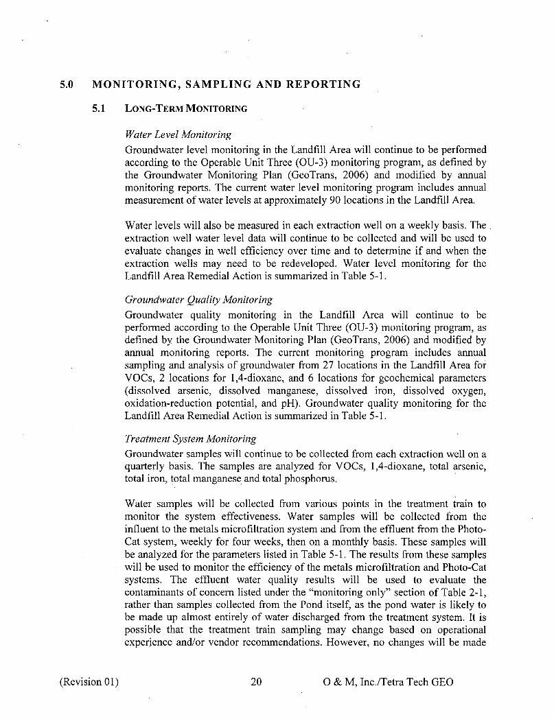
Water Level Monitoring Groundwater level monitoring in the Landfill Area will continue to be performed according to the Operable Unit Three (OU-3) monitoring program, as defined by the Groundwater Monitoring Plan (GeoTrans, 2006) and modified by annual monitoring reports. The current water level monitoring program includes annual measurement of water levels at approximately 90 locations in the Landfill Area.
Water levels will also be measured in each extraction well on a weekly basis. The extraction well water level data will continue to be collected and will be used to evaluate changes in well efficiency over time and to determine if and when the extraction wells may need to be redeveloped. Water level monitoring for the Landfill Area Remedial Action is summarized in Table 5-1.
Groundwater Quality Monitoring Groundwater quality monitoring in the Landfill Area will continue to be performed according to the Operable Unit Three (OU-3) monitoring program, as defined by the Groundwater Monitoring Plan (GeoTrans, 2006) and modified by annual monitoring reports. The current monitoring program includes annual sampling and analysis of groundwater from 27 locations in the Landfill Area for VOCs, 2 locations for 1,4-dioxane, and 6 locations for geochemical parameters (dissolved arsenic, dissolved manganese, dissolved iron, dissolved oxygen, oxidation-reduction potential, and pH). Groundwater quality monitoring for the Landfill Area Remedial Action is summarized in Table 5-1.
Treatment System Monitoring Groundwater samples will continue to be collected from each extraction well on a quarterly basis. The samples are analyzed for VOCs, 1,4-dioxane, total arsenic, total iron, total manganese and total phosphorus.
Water samples will be collected from various points in the treatment train to monitor the system effectiveness. Water samples will be collected from the influent to the metals microfiltration system and from the effluent from the PhotoCat system, weekly for four weeks, then on a monthly basis. These samples will be analyzed for the parameters listed in Table 5-1. The results from these samples will be used to monitor the efficiency of the metals microfiltration and Photo-Cat systems. The effluent water quality results will be used to evaluate the contaminants of concern listed under the "monitoring only" section of Table 2-1, rather than samples collected from the Pond itself, as the pond water is likely to be made up almost entirely of water discharged from the treatment system. It is possible that the treatment train sampling may change based on operational experience and/or vendor recommendations. However, no changes will be made
(Revision 01) 20 O&M, Inc./Tetra Tech GEO
without approval of USEPA.
Samples of the treatment system discharge will be sent for whole effluent toxicity testing. The whole effluent toxicity testing will consist of Ceriodaphnia dubia and Pimephales promelas chronic toxicity tests. The laboratory conducting the toxicity tests will measure water quality parameters of the sample including dissolved oxygen, pH, conductivity, hardness, alkalinity, and total residual chlorine. Whole effluent toxicity testing will be conducted on a quarterly basis for the first year, after which the frequency and/or need for continued toxicity testing will be evaluated. An Addendum to the Quality Assurance Project Plan, describing the toxicity testing, is included as Appendix F.
No air samples will be collected since the Photo-Cat system destroys VOCs, resulting in the groundwater treatment system having no air emissions. Treatment system monitoring for the Landfill Area Remedial Action is summarized in Table 5-1.
Extraction Well Monitoring
Extraction well monitoring will be done weekly with the following data recorded during each monitoring event:
• Record the water level for each extraction well; • Record totalizer reading for each extraction well; and • Record flow rate for each extraction well.
(Revision 01) 21 O & M, Inc./Tetra Tech GEO

Table 5-1
Monitoring and Sampling for Landfill Area Remedial Action
Location
Approximately 90 locations Extraction Wells (5)
27 locations 2 locations 6 locations
Extraction Wells (5)
Influent to Metals Microfiltration System & Effluent from Photo-Cat System**
Effluent from Treatment System
Extraction Wells (5)
Analysis Water Level Monitoring
Hand Measurement Hand measurement
Groundwater Quality Monitoring VOCs 1,4-dioxane geochemical parameters (dissolved arsenic, dissolved manganese, dissolved iron, dissolved oxygen, oxidation-reduction potential, and pH). Treatment System Monitoring
VOCs 1,4-dioxane Total arsenic Total iron Total manganese Total phosphorus chloroethane, MTBE, MEK, VDC, vinyl chloride*, benzene, 1,2dichloroethane*, 1,2dichloropropane*, methylene chloride, TCE, bis (2-chloroethyl) ether*, bis (2-ethylhexyl) phthalate*, 1,4-dioxane, total arsenic, total chromium, total iron, total lead, total manganese, total nickel, total beryllium and total phosphorus Whole effluent toxicity testing
Totalizer Reading/Flow Rate
Frequency
Annually Weekly
Annually Annually Annually
Quarterly
Weekly for 4 weeks; Monthly thereafter
Quarterly for 1 year; Need/Frequency to be determined thereafter Weekly
* Minimum "Related Numeric Criteria" associated with monitoring only discharge requirement (listed in Table 2-1) is below the reporting limit specified in the QAPP (HSI GeoTrans, 2000). ** Subject to change based on operational experience and vendor recommendations.
(Revision 01) 22 O&M, Inc/Tetra Tech GEO

5.2 REPORTING
Monitoring and sampling results related to installation and start-up of the Landfill Area remedial action will be included in the Landfill Area Groundwater Remedial Action Report, which will be submitted within, 90 days after USEPA determines that construction is complete and that the Landfill Area Groundwater Remedial Action is "Operational and Functional".
Long-term monitoring and sampling results related to the Landfill Area remedial action will be reported in one of two documents:
• Annual Monitoring Program Reports or • Annual Groundwater Treatment System Reports.
The annual Monitoring Program Reports for the Site will be submitted following completion of the annual Site-wide water level and groundwater sampling round. The following information will be included in the Monitoring Program Reports:
• A brief description of the water level and water quality sampling procedures;
• A table summarizing the water level measurements; • Unconsolidated deposits and bedrock potentiometric maps showing water
level elevations and potentiometric contours; • Evaluation of Landfill Area capture zone; • Tables summarizing the water quality data; • Unconsolidated deposits and bedrock water quality maps indicating the
VDC, vinyl chloride, and benzene concentrations detected in each monitoring well;
• Contour maps showing the distribution of VDC, vinyl chloride, and benzene concentrations above MCLs; . .
• Maps showing the distribution of arsenic in groundwater; • Time-concentration plots of VDC, vinyl chloride and benzene; • A discussion of any statistically significant water quality concentration
trends observed; and • Discussion/proposal of changes to the monitoring program, including a
listing of monitoring wells, if any, that should be dropped from annual sampling.
(Revision 01) 23 O & M, Inc./Tetra Tech GEO
The annual Groundwater Treatment System Reports for the Site will be submitted by the end of the first quarter of each calendar year. The following information will be included in the Groundwater Treatment System Reports:
• Tables summarizing the treatment system water quality sampling results; • Estimate of the VOC mass removed by the remedy; • Summary of metals microfiltration system and photocatalytic oxidation
system removal efficiencies; • Tables summarizing extraction rates; • Discussion of operation and maintenance activities performed; and • Discussion of issues, if any, related to the treatment system operation.
(Revision 01) 24 O & M, Inc./Tetra Tech GEO

6.0 POTENTIAL OPERATING PROBLEMS AND C O R R E C T I V E ACTIONS
This section is a listing of the most likely potential problems with the GWTS, their possible causes and corrective actions.
6.1 EQUIPMENT MALFUNCTIONS
Table 6-1 lists general equipment malfunctions, probable causes, and in most cases, corrective actions to be taken. By no means is this list complete. It is intended only as a guide for the maintenance personnel to help them in properly identifying and isolating equipment malfunctions. Equipment specific troubleshooting guidelines are presented in Section 6 of the Siemens Wastewater Treatment System Operation and Maintenance Manual (Appendix B), Section 7 of the Siemens J-Press Filter Press Owner's Manual. (Appendix C), and Section 12 of the Purifies PhotoCat Operation and Maintenance Manual (Appendix E). If in doubt as to the actual cause of a malfunction, consult the equipment manufacturer for assistance.
The GWTS will automatically shut down and will need to be restarted manually under the following conditions:
1. Motor fault in any GWTS pump. 2. Electrical fault in any control panel. 3. High-high level alarm in any tank. 4. Any shutdown of the PhotoCat unit. 5. Any shutdown of the air compressor system. 6. Loss of Site electrical power.
In the event the system shuts down, the cause will be investigated, an appropriate remedy implemented, and the system restarted. All other alarms do not require immediate attention by the operator.
6.2 EXCEEDANCE OF A GROUNDWATER DISCHARGE STANDARD
In the event the effluent from the GWTS exceeds a groundwater discharge standard, the following steps will be taken:
1. Notify the EPA and MassDEP within one (1) business day of learning of the exceedance.
2. If an arsenic, iron, or phosphorus discharge standard is exceeded, inspect the microfiltration system and make any required adjustments or repairs and resample the GWTS effluent.
(Revision 01) 25 O & M, Inc./Tetra Tech GEO

3. If chromium III, lead or nickel discharge standard is exceeded, discussions will be initiated with the EPA and MassDEP. These compounds are not typically present at this Site and the existing GWTS is not designed to treat for these compounds.
4. If 1,4 dioxane is detected above its Drinking Water MCL listed in Table 2-1, inspect the Photo-Cat system, make any required adjustments or repairs and resample the GWTS effluent.
5. If a parameter listed as 'monitoring only' in Table 2-1 is detected above its related numeric criteria, discussions will be initiated with EPA and MassDEP.
6. If the toxicity discharge standards are exceeded, discussions will be initiated with the EPA and MassDEP.
Table 6-1 summarizes operational problems that may be encountered during system operation, and potential remedies for each problem.
(Revision 01) 26 O & M, Inc./Tetra Tech GEO
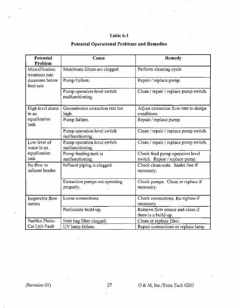
Table 6-1
Potential Operational Problems and Remedies
Remedy
Perform cleaning cycle
Repair / replace pump.
Clean / repair / replace pump switch.
Adjust extraction flow rate to design conditions. Repair / replace pump.
Clean / repair / replace pump switch.
Clean / repair / replace pump switch.
Check feed pump operation level switch. Repair / replace pump. Check clean-outs. Snake line if necessary.
Check pumps. Clean or replace if necessary.
Check connections. Re-tighten if necessary. Remove flow sensor and clean if there is a build-up. Clean or replace filter. Repair connections or replace lamp.
Potential Problem
Microfiltration treatment rate decreases below feed rate
High level alarm in an equalization tank
Low level of water in an equalization tank
No flow in influent header
Inoperable flow meters
Purifies PhotoCat Unit Fault
Cause
Membrane filters are clogged
Pump Failure.
Pump operation level switch malfunctioning.
Groundwater extraction rate too high. Pump failure.
Pump operation level switch malfunctioning. Pump operation level switch malfunctioning. Pump feeding tank is malfunctioning. Influent piping is clogged.
Extraction pumps not operating properly.
Loose connections.
Particulate build-up.
Inlet bag filter clogged. UV lamp failure.
(Revision 01) 27 O&M, Inc/Tetra Tech GEO
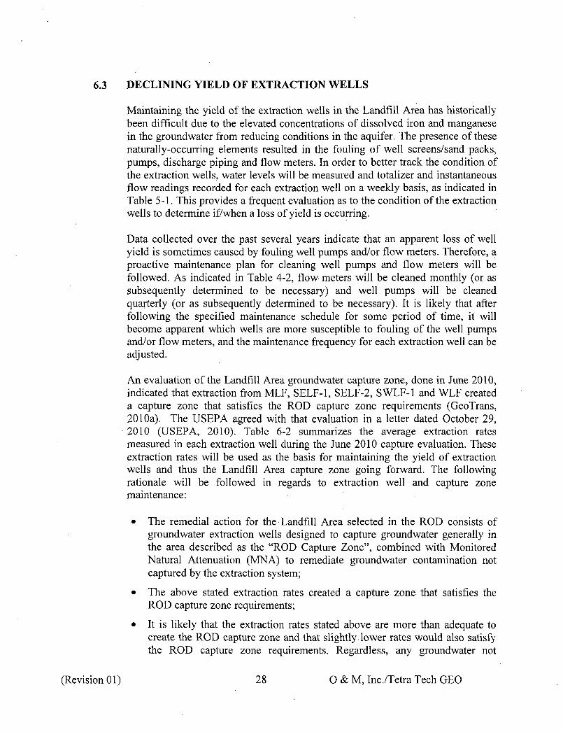
6.3 DECLINING YIELD OF EXTRACTION WELLS
Maintaining the yield of the extraction wells in the Landfill Area has historically been difficult due to the elevated concentrations of dissolved iron and manganese in the groundwater from reducing conditions in the aquifer. The presence of these naturally-occurring elements resulted in the fouling of well screens/sand packs, pumps, discharge piping and flow meters. In order to better track the condition of the extraction wells, water levels will be measured and totalizer and instantaneous flow readings recorded for each extraction well on a weekly basis, as indicated in Table 5-1. This provides a frequent evaluation as to the condition of the extraction wells to determine if/when a loss of yield is occurring.
Data collected over the past several years indicate that an apparent loss of well yield is sometimes caused by fouling well pumps and/or flow meters. Therefore, a proactive maintenance plan for cleaning well pumps and flow meters will be followed. As indicated in Table 4-2, flow meters will be cleaned monthly (or as subsequently determined to be necessary) and well pumps will be cleaned quarterly (or as subsequently determined to be necessary). It is likely that after following the specified maintenance schedule for some period of time, it will become apparent which wells are more susceptible to fouling of the well pumps and/or flow meters, and the maintenance frequency for each extraction well can be adjusted.
An evaluation of the Landfill Area groundwater capture zone, done in June 2010, indicated that extraction from MLF, SELF-1, SELF-2, SWLF-1 and WLF created a capture zone that satisfies the ROD capture zone requirements (GeoTrans, 2010a). The USEPA agreed with that evaluation in a letter dated October 29, 2010 (USEPA, 2010). Table 6-2 summarizes the average extraction rates measured in each extraction well during the June 2010 capture evaluation. These extraction rates will be used as the basis for maintaining the yield of extraction wells and thus the Landfill Area capture zone going forward. The following rationale will be followed in regards to extraction well and capture zone maintenance:
• The remedial action for the Landfill Area selected in the ROD consists of groundwater extraction wells designed to capture groundwater generally in the area described as the "ROD Capture Zone", combined with Monitored Natural Attenuation (MNA) to remediate groundwater contamination not captured by the extraction system;
• The above stated extraction rates created a capture zone that satisfies the ROD capture zone requirements;
• It is likely that the extraction rates stated above are more than adequate to create the ROD capture zone and that slightly lower rates would also satisfy the ROD capture zone requirements. Regardless, any groundwater not
(Revision 01) 28 O&M, Inc./Tetra Tech GEO

captured by the extraction system would be remediated by MNA;
The following procedures will be followed:
o Track specific capacity (pumping rate in gpm/feet of drawdown);
o Compare current specific capacity to the wells specific capacity as measured in June 2010 (Table 6-2);
o When a 10% to 15% loss in specific capacity is observed, determine the cause and correct the problem. Table 6-3 summarizes the steps to be taken and the estimated timeframe for each step;
o Rehabilitate the well before 25% of specific capacity is lost.
If rehabilitation does not restore well yield and specific capacity, then either re-evaluate the Landfill Area Capture Zone to determine if the current extraction rates are attaining an adequate capture zone or install a replacement extraction well;
o Re-evaluation of the capture zone consists of:
o Collecting water levels in the monitoring wells in the Landfill Area and preparing potentiometric maps and sections similar to Figures 10 through 15 in the June 2010 capture zone evaluation (GeoTrans, 2010a); and
o Submitting the results to USEPA and MassDEP for review and approval;
o Replacement of an extraction well consists of submitting a proposed well design and schedule to USEPA and MassDEP for review and approval.
Table 6-2
June 2010 Extraction Rates and Specific Capacities
June 20: 10 Water Level
Elevation (feet Specific Flow NGVD) Capacity
Extraction Rate Not Drawdown (gpm/ft Well (gpm) Pumping Pumping (feet)* drawdown) MLF 37.7 137.6 130.7 6.5 5.800
SELF-1 1.2 135.6 117.1 18.1 0.066 SELF-2 1.3 134.5 118 16.1 0.08.1 SWLF-1 2.4 137.3 34.3 102.6 0.023
WLF 8.4 137.6 111.9 25.3 0.332 Adjusted for background water level change.
(Revision 01) 29 O&M, Inc/Tetra Tech GEO
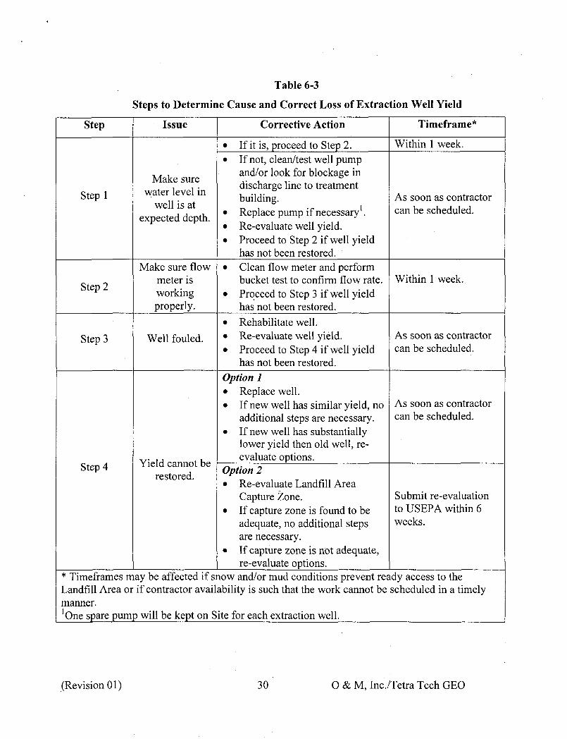
Table 6-3
Steps to Determine Cause and Correct Loss of Extraction Well Yield
Step Issue
Make sure water level in Stepl
well is at expected depth.
Make sure flow meter is
Step 2 working properly.
Step 3 Well fouled.
Yield cannot be Step 4 restored.
Corrective Action
• If it is, proceed to Step 2. • If not, clean/test well pump
and/or look for blockage in discharge line to treatment building.
• Replace pump if necessary1. • Re-evaluate well yield. • Proceed to Step 2 if well yield
has not been restored. • Clean flow meter and perform
bucket test to confirm flow rate. • Proceed to Step 3 if well yield
has not been restored. • Rehabilitate well. • Re-evaluate well yield. • Proceed to Step 4 if well yield
has not been restored. Option 1 • Replace well. • If new well has similar yield, no
additional steps are necessary. • If new well has substantially
lower yield then old well, reevaluate options.
Option 2 • Re-evaluate Landfill Area
Capture Zone. • If capture zone is found to be
adequate, no additional steps are necessary.
• If capture zone is not adequate, re-evaluate options.
Timeframe*
Within 1 week.
As soon as contractor can be scheduled.
Within 1 week.
As soon as contractor can be scheduled.
As soon as contractor can be scheduled.
Submit re-evaluation to USEPA within 6 weeks.
* Timeframes may be affected if snow and/or mud conditions prevent ready access to the Landfill Area or if contractor availability is such that the work cannot be scheduled in a timely manner. 'One spare pump will be kept on Site for each extraction well.
(Revision 01) 30 O&M, Inc./Tetra Tech GEO
7.0 DOCUMENTATION
An important factor in operating any efficient extraction and treatment system is the completion of accurate operational and maintenance records. Without a record of past operational performance, it is, impossible to identify trends in any. process. Records provide the operators with valuable information upon which to base their decisions concerning the system operation.
Four types of GWTS records will be maintained at the site: operating reports, maintenance records, emergency condition records, and personnel records. These records are discussed further in the following sections.
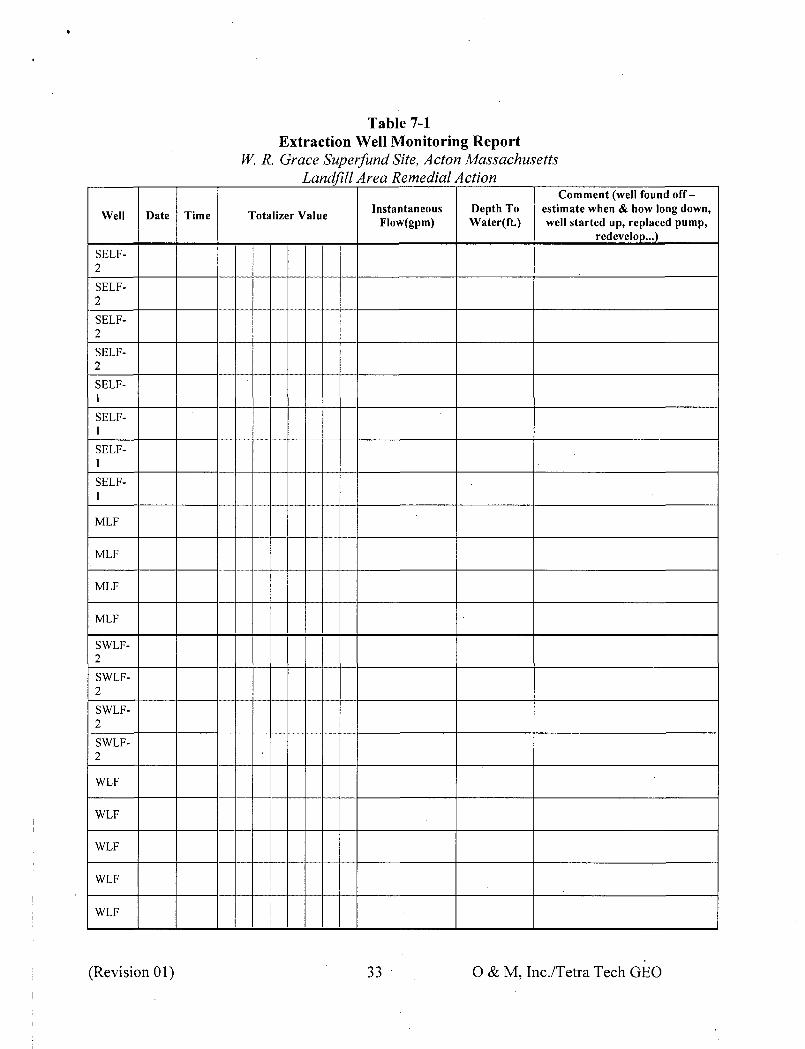
7.1 OPERATING REPORTS
Detailed operating reports will be maintained for GWTS operation. These reports will be used to record information that is integral to observing and controlling operational trends of the GWTS. Table 7-1 presents an example Monthly GWTS Inspection Report, which will be filled in monthly and an Extraction Well Monitoring Report, which will be filled in weekly. Table 5-1 summarizes the frequency of data collection.
(Revision 01) 31 O&M, Inc./Tetra Tech GEO

Table 7-1
Monthly GWTS Inspection Report W. R. Grace Superfund Site, Acton Massachusetts
Landfill Area Remedial Action
Date: Weather:
Equipment/Personnel On-Site:
Description of Work Performed:
Influent Transfer Pump 1 Pressure psi Flow ,gpm
Influent Transfer Pump 2 Pressure psi Flow gpm
RXN Tank 1 pH ORP RXN Tank 2 pH ORP
Sodium Hypochlorite Feed Rate ml/min Sodium Hydroxide Feed Rate ml/min
MMF Trains 1 & 2 Flow Rate gpm i Pump Inlet Pressure psi Outlet psi
MMF Trains 3 & 4 Flow Rate gpm i Pump Inlet Pressure psi Outlet psi
Neutralization Tank pH
Effluent Transfer Pump 1 Pressure psi Flow gpm
Effluent Transfer Pump 2 Pressure psi Flow gpm
Plant Water Pump 1 Pressure psi Flow gpm
Plant Water Pump 2 Pressure psi Flow gpm
Sludge Thickener Feed Pump Pressure psi Filter Press Feed Pump Pressure psi
Filtrate Tank Pump Pressure psi
Purifies System Operating? Y / N
Ozone Feed Rate ml/min
Additional Information:
(Revision 01) 32 O&M, Inc./Tetra Tech GEO
Well
SELF2
SELF2
SELF2
SELF2
SELF1
SELF1
SELF1
SELF1
MLF
MLF
MLF
MLF
SWLF2
SWLF2
SWLF2
SWLF2
WLF
WLF
WLF
WLF
WLF
Table 7-1 Extraction Well Monitoring Report
W. R. Grace Superfund Site, Acton Massachusetts Landfill Area Remedial Action
Comment (well found off-Instantaneous Depth To estimate when & how long down,
Date Time Totalizer Value Flow(gpm) Water(ft.) well started up, replaced pump,
redevelop...)
(Revision 01) 33 O&M, Inc./Tetra Tech GEO
7.2 MAINTENANCE RECORDS
Record completion and retention is the most important aspect of the maintenance program. From a review of the maintenance records, operating personnel, the responsible regulatory agency, and the design engineer can identify recurring problems with various pieces of equipment, select the appropriate list of spare parts to be maintained on-site, and develop and design solutions to overcome these problems.
A log book will be maintained on-site to record maintenance activities. In addition, a running.record of maintenance performed on each piece of equipment will be kept. The equipment inspection and service record provides an easily identifiable list of maintenance performed on each piece of equipment. Data concerning the preventive maintenance necessary on each item of equipment is obtained from the manufacturer's O&M manuals, and the next scheduled servicing can be easily indicated.
7.3 NON-ROUTINE CONDITIONS
A record of non-routine conditions affecting the system will be maintained in the site logbook. Example non-routine conditions include: area wide power failures, extraction pump failures, or natural disasters. The logbook also serves as a register of major emergencies or alarm conditions, with supplemental reports filed describing the occurrence, damage, cause, emergency corrective actions taken, costs attributed to the situation, and permanent corrective actions taken, if required.
7.4 PERSONNEL RECORDS
A record of on-site personnel and any visitors, subcontractors, regulatory agency personnel, etc. will be maintained at the Site.
(Revision 01) 34 O & M, Inc./Tetra Tech GEO
8.0 SAFETY ISSUES
A site-specific O&M HASP has been prepared for the Site and is included in Appendix G of this O&M Plan. The HASP contains the following information:
• organization and responsibilities of the project/health and safety team; • characterization of the chemical and physical hazards present at the Site; • a description of the medical program required for O&M personnel; • instruction on selection and use of personal protective equipment (PPE) and action
levels for upgrading or downgrading PPE; • proper delineation of work zones and equipment personal decontamination; and • an accident prevention and contingency plan.
8.1 GENERAL SITE SAFETY
Any piece of equipment can be dangerous if operated improperly. Safety is ultimately the responsibility of those operating and maintaining the equipment. All personnel operating and maintaining the GWTS and its proper implementation must be familiar with all of the system components, and observe all OSHA, federal, state and local safety codes and requirements. The personnel should also be active participants in the approved company health and safety program.
Failure to properly follow instructions and failure to take proper safety precautions is dangerous and can cause serious personal injury, needless equipment damage, and unnecessary environmental harm. Mechanical modifications and/or substitutions of parts on equipment that will affect structural, operational, or environmental safety should not be made. Modifications that may defeat protective features originally designed into the equipment and its controls should not be made.
Table 8-1 summarizes the hazards associated with the GWTS operation. The following is a partial list of general precautions to follow, but in no case is the list exhaustive, nor is it intended to be. Operators and maintenance personnel should expand on this list after first reviewing the entire GWTS and its' operation with the appropriate health and safety authorities. • Always ask or be aware of the required PPE for the work area.
• Keep work areas clean. A clean work area is a much safer area.
• Keep all equipment guards in place. If removed to service the equipment, make sure the guards are replaced properly.
• Wear eye and face protection around rotating and pumping equipment and whenever working around or handling chemicals. Be especially cautious for splash when disconnecting piping, valves and fittings.
(Revision 01) 35 O & M, Inc./Tetra Tech GEO
• Wear ear protection as required.
• Wear proper apparel. Do not wear loose clothing, or jewelry, which could be caught in machinery.
• Wear an appropriate respirator for use around chemicals and in areas where vapors and/or gases may be present.
• Non-skid footwear is recommended and always wear protective gloves when the job requires.
• Remove adjusting screws or wrenches. Form a habit of checking to see that all tools are removed from equipment and return them to their proper storage area.
• Make sure all personnel are familiar with OSHA approved Material Safety Data Sheets for all hazardous materials they may encounter.
Reporting mechanisms for medical emergencies are described in the site health and safety plan (nearest hospital or medical treatment facility, etc.). Signs containing 24-hour emergency phone number contacts are posted in the control room and system compound gates.
(Revision 01) 36 O & M, Inc./Tetra Tech GEO
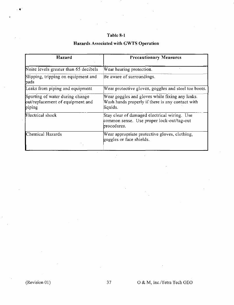
Table 8-1
Hazards Associated with GWTS Operation
Hazard
Noise levels greater than 65 decibels
Slipping, tripping on equipment and pads
Leaks from piping and equipment
Spurting of water during change out/replacement of equipment and piping
Electrical shock
Chemical Hazards
Precautionary Measures
Wear hearing protection.
Be aware of surroundings.
Wear protective gloves, goggles and steel toe boots.
Wear goggles and gloves while fixing any leaks. Wash hands properly if there is any contact with liquids.
Stay clear of damaged electrical wiring. Use common sense. Use proper lock-out/tag-out procedures.
Wear appropriate protective gloves, clothing, goggles or face shields.
(Revision 01) 37 O&M, Inc./Tetra Tech GEO

- * •
9.0 R E F E R E N C E S
GeoTrans, 2006, Groundwater Monitoring Plan, September 12, 2006.
GeoTrans, 2007, Project Operations Plan Addendum, February 1, 2007.
GeoTrans 2010a, Letter to USEPA and MassDEP RE: Installation of Extraction well SELF-2, Decommissioning of Extraction Wells ELF and RLF, and Re-Evaluation of Landfill Area Groundwater Capture Zone, August 18, 2010.
GeoTrans, 2010b, Landfill Area Groundwater Final Design, December 13, 2010.
HIS GeoTrans, 2000, Project Operations Plan (Revised). March 10, 2000.
USEPA, 2005. Record of Decision, W. R. Grace & Co. (Acton Plant) Superfund Site, Operable Unit Three, Towns of Acton and Concord, Middlesex County, Massachusetts. September 2005.
USEPA, 2006. Remedial Design/Remedial Action Statement of Work W.R. Grace (Acton Plant) Superfund Site, Acton & Concord, MA, August 30, 2006.
USEPA, 2010, Letter to de maximis Re: EPA & MassDEP Comments and Conditional Approval on the following reports: Landfill Area Groundwater Concept Design, dated 9/8/09; Additional Information Related to Landfill Area Groundwater Concept Design, dated 10/23/09 and the Landfill Area Groundwater Capture Zone Evaluation, dated 11/19/09, January 22, 2010.
(Revision 01) 38 O&M, Inc./Tetra Tech GEO

Environmental Operations and Maintenance Management
450 Montbrook Lane Knoxville, TN 37919
(865)691-6254 FAX (865) 691-9595
Acct. FAX (865) 691-9835
April 4, 2012
Mr: Derrick Golden Ms. Jennifer McWeeney Waste Management Division Bureau of Waste Site Cleanup U.S. Environmental Protection Agency Massachusetts Department of Region I Environmental Protection. 5 Post Office Square One Winter Street, 7th Floor Mail Code OSRR07-4 Boston, MA 02108 Boston, MA 02109-3912
RE: Landfill Area Groundwater Operation and Maintenance Plan Revision 01, W. R. Grace Superfund Site, Acton, Massachusetts
Dear Mr. Golden and Ms. McWeeney:
Attached is the Landfill Area Groundwater Operation and Maintenance Plan Revision 01. The revisions were limited to the main text. We have sent one hard copy of the main text of the document to each recipient. If you have any questions regarding the enclosed documents please call me at (978) 952-0120.
Projeer Manager Thor Helgason, PE
cc: Electronic Only Lydia Duff, W. R. Grace. Lynne Gardner, W. R. Grace Jack Guswa, JG Environmental Seth Jaffe, Foley Hoag Bob Medler, Remedium David Fuerst, O&M, Inc. Anne Sheehan, Tetra Tech GEO
Orrtana, PA • Clinton, NJ • Danville, IN • Knoxville, TN • Westland, Ml • Clearwater, FL Shorewood, Wl • Windsor, CT • Columbia, SC • Philpot. KY • North Billerica, MA • Dallas, GA
fei<9 PAPER