the complete guide to chain - u.s. tsubaki effect of normal chain wear on fatigue strength . . . 20...
TRANSCRIPT

TheComplete Guide to
Chain

U.S. Tsubaki, Inc., Wheeling, Illinois
The Complete Guide to Chain

ii
The Complete Guide to Chain© 1997 by U.S. Tsubaki, Inc.
First English-language edition, 1997ISBN 0-9658932-0-0
Library of Congress 97-061464
Translated and printed with permission of Kogyo Chosakai Publishing Co., Ltd.
Distributed in North America, Australia, and Europeby U.S. Tsubaki, Inc., 301 East Marquardt Drive,Wheeling, Illinois 60090. Originally published by
Kogyo Chosakai Publishing Co., Ltd., under the title:Machine Elements Manual, Chain.
Original Editor: Tsubakimoto Chain Co.Original Publisher: Sachio Shimura
All rights reserved. No part of this book may bereproduced or utilized in any form or by any means,electronic or mechanical, including photocopying,
recording, or by any information storage and retrievalsystem, without permission in writing from
the publisher.

iii
ContributorsSupervising EditorKyosuke Otoshi
DirectorChain Products Division
EditorMakoto Kanehira
ManagerChain Products Division
Production Engineering Department
WritersMakoto Kanehira
ManagerChain Products Division
Production Engineering Department
Tomofumi Otani Manager
Chain Products Division Engineering Department
Chain Engineering Section
Masayuki Yoshikawa Manager
Chain Products Division Engineering Department
Conveyor Chain Engineering Section
Toshio Takahashi Manager
Chain Products Division Roller Chain Production Department
Engineering Plastics Manufacturing Section

CONTRIBUTORS . . . . . . . . . . . . . . . . . . . . . . . . . . . . . . . . . . . . . . . . . . . . . . . . iiPREFACE . . . . . . . . . . . . . . . . . . . . . . . . . . . . . . . . . . . . . . . . . . . . . . . . . . xiiiACKNOWLEDGMENTS . . . . . . . . . . . . . . . . . . . . . . . . . . . . . . . . . . . . . . . . . . . . xv
BASICS SECTION1. CHAIN BASICS . . . . . . . . . . . . . . . . . . . . . . . . . . . . . . . . . . . . 1
1.1 WHAT IS A CHAIN? . . . . . . . . . . . . . . . . . . . . . . . . . . . . . . . . . . . . 11.1.1 Basic Structure of Power Transmission Chain . . . . . . . . . . . . 21.1.2 Basic Structure of Small Pitch Conveyor Chain . . . . . . . . . . . 41.1.3 Basic Structure of Large Pitch Conveyor Chain—
Engineering Class . . . . . . . . . . . . . . . . . . . . . . . . . . . . . . . . 41.1.4 Functions of Chain Parts . . . . . . . . . . . . . . . . . . . . . . . . . . . 4
1.2 ADVANTAGES AND DISADVANTAGES OF CHAIN FORPOWER TRANSMISSION AND CONVEYORS . . . . . . . . . . . . . . . . . . 61.2.1 Power Transmission Uses . . . . . . . . . . . . . . . . . . . . . . . . . . . 61.2.2 Conveyance Uses . . . . . . . . . . . . . . . . . . . . . . . . . . . . . . . . . 8
1.3 SPROCKETS . . . . . . . . . . . . . . . . . . . . . . . . . . . . . . . . . . . . . . . . 8
2. CHAIN DYNAMICS . . . . . . . . . . . . . . . . . . . . . . . . . . . . . . . . 9
2.1 CHAINS UNDER TENSION . . . . . . . . . . . . . . . . . . . . . . . . . . . . . . . 9
2.1.1 Elastic Stretch, Plastic Deformation, and Breakage . . . . . . . . . 92.1.2 Engagement with Sprockets . . . . . . . . . . . . . . . . . . . . . . . . 12
2.2 CHAIN DRIVE IN ACTION . . . . . . . . . . . . . . . . . . . . . . . . . . . . . . . 152.2.1 Chordal Action . . . . . . . . . . . . . . . . . . . . . . . . . . . . . . . . . . 152.2.2 Repeated Load Tension, Fatigue Failure . . . . . . . . . . . . . . . 172.2.3 Transmission Capability of Drive Chains . . . . . . . . . . . . . . . 19
2.2.3.1 Difference Between Linear Tension and Wrapping . . 192.2.3.2 Effect of Normal Chain Wear on Fatigue Strength . . . 202.2.3.3 Strength Differences Between Chain and the
Connecting Links and Offset Links . . . . . . . . . . . . . 202.2.4 Wear of Working Parts . . . . . . . . . . . . . . . . . . . . . . . . . . . . 222.2.5 Noise and Vibration . . . . . . . . . . . . . . . . . . . . . . . . . . . . . . 23
2.3 CHARACTERISTIC PHENOMENA IN CONVEYOR CHAIN . . . . . . . . . 242.3.1 Coefficient of Friction . . . . . . . . . . . . . . . . . . . . . . . . . . . . . 242.3.2 Dynamic Tension of Starting and Stopping . . . . . . . . . . . . . 262.3.3 Wear Between Rollers and Bushings . . . . . . . . . . . . . . . . . . 27
v
Contents

vi
2.3.4 Strength of Attachments . . . . . . . . . . . . . . . . . . . . . . . . . . . 282.3.5 Stick Slip . . . . . . . . . . . . . . . . . . . . . . . . . . . . . . . . . . . . . . 282.3.6 Relative Differences in Chain’s Total Length . . . . . . . . . . . . 292.3.7 Take-Up . . . . . . . . . . . . . . . . . . . . . . . . . . . . . . . . . . . . . . 29
3. PUBLIC STANDARDS OF CHAINS . . . . . . . . . . . . . . 31
4. HOW TO SELECT CHAINS . . . . . . . . . . . . . . . . . . . . . . . 32
4.1 TRANSMISSION CHAIN SELECTION . . . . . . . . . . . . . . . . . . . . . . . 324.1.1 Chain Selection Factors . . . . . . . . . . . . . . . . . . . . . . . . . . . 334.1.2 Coefficients Used in Selection . . . . . . . . . . . . . . . . . . . . . . . 344.1.3 Drive Chain Selection (General Selection) . . . . . . . . . . . . . . 364.1.4 Power Transmission Chain Selection for Slow Speeds . . . . . 394.1.5 Hanging Transmission Chain Selection . . . . . . . . . . . . . . . . 41
4.2 CONVEYOR CHAIN SELECTION . . . . . . . . . . . . . . . . . . . . . . . . . . 474.2.1 Check of Conditions for Selection . . . . . . . . . . . . . . . . . . . . 474.2.2 Conveyor Type Selection . . . . . . . . . . . . . . . . . . . . . . . . . . 484.2.3 Selection of Chain Type and Specification . . . . . . . . . . . . . 504.2.4 Points of Notice About Roller Type . . . . . . . . . . . . . . . . . . 504.2.5 Chain Pitch Decision . . . . . . . . . . . . . . . . . . . . . . . . . . . . . 514.2.6 Deciding the Number of Sprocket Teeth . . . . . . . . . . . . . . . 514.2.7 Deciding the Attachment Type . . . . . . . . . . . . . . . . . . . . . . 524.2.8 Calculation of Tension . . . . . . . . . . . . . . . . . . . . . . . . . . . . 52
4.2.8.1 Horizontal Conveyor . . . . . . . . . . . . . . . . . . . . . . . . 534.2.8.2 Free Flow Conveyor . . . . . . . . . . . . . . . . . . . . . . . . 53
4.2.9 Allowable Load of Roller and Standard A Attachment . . . . . 544.3 SELECTION EXAMPLE . . . . . . . . . . . . . . . . . . . . . . . . . . . . . . . . . 55
5. CHAINS AND ENVIRONMENTS . . . . . . . . . . . . . . . . . 57
5.1 STEEL CHAINS . . . . . . . . . . . . . . . . . . . . . . . . . . . . . . . . . . . . . . 57
5.1.1 Use of Steel Chains in High Temperatures . . . . . . . . . . . . . . 575.1.2 Use of Steel Chains in Low Temperatures . . . . . . . . . . . . . . 58
5.2 ENGINEERED PLASTIC CHAIN IN HIGH AND LOW TEMPERATURES . 585.3 OTHER CHAIN MATERIALS IN HIGH TEMPERATURES . . . . . . . . . . . 595.4 COPING WITH SPECIAL CONDITIONS . . . . . . . . . . . . . . . . . . . . . . 59
5.4.1 Use in Wet Conditions . . . . . . . . . . . . . . . . . . . . . . . . . . . . 595.4.2 Use in Acidic, Alkaline, or Electrolytic Conditions . . . . . . . . 605.4.3 Use in Abrasive Conditions . . . . . . . . . . . . . . . . . . . . . . . . 60
vii
6. BASIC LAYOUTS . . . . . . . . . . . . . . . . . . . . . . . . . . . . . . . . . . 63
6.1 BASIC LAYOUTS OF WRAPPING TRANSMISSION CHAINS . . . . . . . 63
6.1.1 General Arrangements . . . . . . . . . . . . . . . . . . . . . . . . . . . . 636.1.2 Special Layouts . . . . . . . . . . . . . . . . . . . . . . . . . . . . . . . . . 646.1.3 Special Arrangements . . . . . . . . . . . . . . . . . . . . . . . . . . . . . 65
6.2 BASIC CONVEYOR CHAIN LAYOUTS . . . . . . . . . . . . . . . . . . . . . . . 656.2.1 Horizontal Conveyor Arrangement . . . . . . . . . . . . . . . . . . . 656.2.2 Vertical Conveyor Arrangement . . . . . . . . . . . . . . . . . . . . . . 676.2.3 Inclined Conveyor Arrangement . . . . . . . . . . . . . . . . . . . . . 676.2.4 Horizontal Circulating Conveyor Arrangement . . . . . . . . . . . 67
6.3 SUPPORTING THE ROLLER OF A CONVEYOR CHAIN . . . . . . . . . . . 67
7. MANIPULATION OF CHAINS . . . . . . . . . . . . . . . . . . . . 69
7.1 TRANSMISSION CHAINS, SMALL PITCH CONVEYOR CHAINS . . . . 69
7.1.1 Installation . . . . . . . . . . . . . . . . . . . . . . . . . . . . . . . . . . . . 697.1.2 Installation Accuracy . . . . . . . . . . . . . . . . . . . . . . . . . . . . . 70
7.1.2.1 Chain Slack . . . . . . . . . . . . . . . . . . . . . . . . . . . . . . 707.1.2.2 Horizontal Precision and Parallelism of the Shafts . . 71
7.1.3 Start-Up . . . . . . . . . . . . . . . . . . . . . . . . . . . . . . . . . . . . . . . 727.1.3.1 Prestart-Up Checklist . . . . . . . . . . . . . . . . . . . . . . . 727.1.3.2 Start-Up Test . . . . . . . . . . . . . . . . . . . . . . . . . . . . . 72
7.1.4 Lubrication . . . . . . . . . . . . . . . . . . . . . . . . . . . . . . . . . . . . 727.1.5 Inspection . . . . . . . . . . . . . . . . . . . . . . . . . . . . . . . . . . . . . 737.1.6 Troubleshooting and Problem-Solving . . . . . . . . . . . . . . . . . 74
7.2 LARGE PITCH CONVEYOR CHAINS . . . . . . . . . . . . . . . . . . . . . . . . 797.2.1 Installation . . . . . . . . . . . . . . . . . . . . . . . . . . . . . . . . . . . . 797.2.2 Installation Accuracy . . . . . . . . . . . . . . . . . . . . . . . . . . . . . 80
7.2.2.1 Chain Tension . . . . . . . . . . . . . . . . . . . . . . . . . . . . 807.2.2.2 Horizontal Precision and Parallelism of the Shafts . . 807.2.2.3 Accuracy of the Rails . . . . . . . . . . . . . . . . . . . . . . . 80
7.2.3 Start-Up . . . . . . . . . . . . . . . . . . . . . . . . . . . . . . . . . . . . . . . 807.2.4 Lubrication . . . . . . . . . . . . . . . . . . . . . . . . . . . . . . . . . . . . 817.2.5 Inspection . . . . . . . . . . . . . . . . . . . . . . . . . . . . . . . . . . . . . 817.2.6 Troubleshooting and Problem-Solving . . . . . . . . . . . . . . . . . 81

APPLICATIONS SECTION1. TRANSMISSION CHAINS . . . . . . . . . . . . . . . . . . . . . . . . 85
1.1 STANDARD ROLLER CHAINS . . . . . . . . . . . . . . . . . . . . . . . . . . . . 861.1.1 ANSI Roller Chains (RS) . . . . . . . . . . . . . . . . . . . . . . . . . . . 861.1.2 BS/DIN Roller Chain . . . . . . . . . . . . . . . . . . . . . . . . . . . . . 87
1.2 HIGH PERFORMANCE CHAINS . . . . . . . . . . . . . . . . . . . . . . . . . . . 881.2.1 Super Roller Chain . . . . . . . . . . . . . . . . . . . . . . . . . . . . . . . 891.2.2 Super-H Roller Chain . . . . . . . . . . . . . . . . . . . . . . . . . . . . . 911.2.3 RS-HT Roller Chain . . . . . . . . . . . . . . . . . . . . . . . . . . . . . . 921.2.4 Ultra Super Chain . . . . . . . . . . . . . . . . . . . . . . . . . . . . . . . 93
1.3 LUBE-FREE CHAINS . . . . . . . . . . . . . . . . . . . . . . . . . . . . . . . . . . . 941.3.1 LAMBDA® Roller Chain . . . . . . . . . . . . . . . . . . . . . . . . . . . 941.3.2 Sealed Roller Chain . . . . . . . . . . . . . . . . . . . . . . . . . . . . . . 96
1.4 ENVIRONMENTALLY RESISTANT CHAINS . . . . . . . . . . . . . . . . . . . 981.4.1 Nickel-Plated Roller Chain (NP) . . . . . . . . . . . . . . . . . . . . 1001.4.2 WP® Roller Chain . . . . . . . . . . . . . . . . . . . . . . . . . . . . . . 1021.4.3 Stainless Steel Roller Chain (SS) . . . . . . . . . . . . . . . . . . . . 1031.4.4 Poly-Steel Chain (PC) . . . . . . . . . . . . . . . . . . . . . . . . . . . 107
1.5 SPECIALTY CHAINS, TYPE 1 . . . . . . . . . . . . . . . . . . . . . . . . . . . . 1091.5.1 Bicycle Chain . . . . . . . . . . . . . . . . . . . . . . . . . . . . . . . . . . 1091.5.2 Motorcycle Chain . . . . . . . . . . . . . . . . . . . . . . . . . . . . . . 1121.5.3 Chains for Automotive Engines . . . . . . . . . . . . . . . . . . . . . 115
1.6 SPECIALTY CHAINS, TYPE 2 . . . . . . . . . . . . . . . . . . . . . . . . . . . . 1171.6.1 Miniature Chain . . . . . . . . . . . . . . . . . . . . . . . . . . . . . . . . 1171.6.2 Leaf Chains . . . . . . . . . . . . . . . . . . . . . . . . . . . . . . . . . . . 1181.6.3 Inverted Tooth Chain (Silent Chain) . . . . . . . . . . . . . . . . . 121
2. SMALL PITCH CONVEYOR CHAINS . . . . . . . . . . . 124
2.1 SMALL PITCH CONVEYOR CHAINS FOR GENERAL USE . . . . . . . . 1262.1.1 RS Attachment Chain . . . . . . . . . . . . . . . . . . . . . . . . . . . . 1262.1.2 Double Pitch Roller Chain . . . . . . . . . . . . . . . . . . . . . . . . 1282.1.3 Plastic Roller Plus Plastic Sleeve Chain . . . . . . . . . . . . . . . 1302.1.4 Hollow Pin Chain . . . . . . . . . . . . . . . . . . . . . . . . . . . . . . 132
2.2 SPECIALTY CHAINS . . . . . . . . . . . . . . . . . . . . . . . . . . . . . . . . . . 1342.2.1 Step (Escalator) Chain . . . . . . . . . . . . . . . . . . . . . . . . . . . 1342.2.2 ATC Chain . . . . . . . . . . . . . . . . . . . . . . . . . . . . . . . . . . . . 136
viii

ix
2.3 STANDARD ATTACHMENTS . . . . . . . . . . . . . . . . . . . . . . . . . . . . 1392.3.1 A Attachment . . . . . . . . . . . . . . . . . . . . . . . . . . . . . . . . . . 1392.3.2 K Attachment . . . . . . . . . . . . . . . . . . . . . . . . . . . . . . . . . . 1402.3.3 SA Attachment . . . . . . . . . . . . . . . . . . . . . . . . . . . . . . . . . 1412.3.4 SK Attachment . . . . . . . . . . . . . . . . . . . . . . . . . . . . . . . . . 1422.3.5 D Attachment (Extended Pin) . . . . . . . . . . . . . . . . . . . . . . 143
2.4 PLUS α ALPHA ATTACHMENTS . . . . . . . . . . . . . . . . . . . . . . . . . 1442.5 SPECIAL ATTACHMENTS . . . . . . . . . . . . . . . . . . . . . . . . . . . . . . 146
3. PRECISION CONVEYOR CHAINS . . . . . . . . . . . . . . 149
3.1 BEARING BUSH CHAIN . . . . . . . . . . . . . . . . . . . . . . . . . . . . . . . 1503.2 INDEXING TABLE CHAIN . . . . . . . . . . . . . . . . . . . . . . . . . . . . . . 153
4. TOP CHAINS . . . . . . . . . . . . . . . . . . . . . . . . . . . . . . . . . . . . 154
4.1 WHAT IS TOP CHAIN? . . . . . . . . . . . . . . . . . . . . . . . . . . . . . . . . 1554.1.1 Plastic Materials for Top Chains . . . . . . . . . . . . . . . . . . . . . 1554.1.2 Guide Rail Materials . . . . . . . . . . . . . . . . . . . . . . . . . . . . . 1564.1.3 Lubrication . . . . . . . . . . . . . . . . . . . . . . . . . . . . . . . . . . . 1574.1.4 Various Accessories . . . . . . . . . . . . . . . . . . . . . . . . . . . . . . 157
4.2 TYPES OF TOP CHAIN . . . . . . . . . . . . . . . . . . . . . . . . . . . . . . . . 1584.2.1 TTP Top Chain . . . . . . . . . . . . . . . . . . . . . . . . . . . . . . . . 1584.2.2 TP Top Chain . . . . . . . . . . . . . . . . . . . . . . . . . . . . . . . . . 1604.2.3 TTUP Top Chain . . . . . . . . . . . . . . . . . . . . . . . . . . . . . . . . 1624.2.4 TPU Top Chain . . . . . . . . . . . . . . . . . . . . . . . . . . . . . . . . . 1644.2.5 TT Top Chain . . . . . . . . . . . . . . . . . . . . . . . . . . . . . . . . . . 1664.2.6 TS Top Chain . . . . . . . . . . . . . . . . . . . . . . . . . . . . . . . . . . 1684.2.7 TTU Top Chain . . . . . . . . . . . . . . . . . . . . . . . . . . . . . . . . 1694.2.8 TO Crescent Top Plate Chain . . . . . . . . . . . . . . . . . . . . . . . 1704.2.9 TN Snap-On Top Plate Chain . . . . . . . . . . . . . . . . . . . . . . . 1724.2.10 RS Plastic Top Chain . . . . . . . . . . . . . . . . . . . . . . . . . . . . 1744.2.11 Bel-Top Chain . . . . . . . . . . . . . . . . . . . . . . . . . . . . . . . . . 175
5. FREE FLOW CHAINS . . . . . . . . . . . . . . . . . . . . . . . . . . . 177
5.1 WHAT IS FREE FLOW CHAIN? . . . . . . . . . . . . . . . . . . . . . . . . . . . 1785.2 TYPES OF FREE FLOW CHAIN . . . . . . . . . . . . . . . . . . . . . . . . . . . 179
5.2.1 DOUBLE PLUS® Chain . . . . . . . . . . . . . . . . . . . . . . . . . . . 1795.2.2 Outboard Roller Chain—Side Roller Type . . . . . . . . . . . . . 1845.2.3 Outboard Roller Chain—Top Roller Type . . . . . . . . . . . . . . 1875.2.4 Roller Table Chain (ST, RT) . . . . . . . . . . . . . . . . . . . . . . . . 189

x
6. LARGE PITCH CONVEYOR CHAINS . . . . . . . . . . . 192
6.1 WHAT IS LARGE PITCH CONVEYOR CHAIN? . . . . . . . . . . . . . . . . 1936.1.1 Standards . . . . . . . . . . . . . . . . . . . . . . . . . . . . . . . . . . . . . 1936.1.2 Nomenclature . . . . . . . . . . . . . . . . . . . . . . . . . . . . . . . . . . 1936.1.3 Construction and Features . . . . . . . . . . . . . . . . . . . . . . . . . 194
6.1.3.1 Shape Features . . . . . . . . . . . . . . . . . . . . . . . . . . . 1946.1.3.2 Function Features . . . . . . . . . . . . . . . . . . . . . . . . . 1946.1.3.3 Disadvantages . . . . . . . . . . . . . . . . . . . . . . . . . . . . 196
6.2 STANDARD CONVEYOR CHAINS . . . . . . . . . . . . . . . . . . . . . . . . 1986.2.1 RF Conveyor Chain . . . . . . . . . . . . . . . . . . . . . . . . . . . . . . 1986.2.2 RF Bearing Roller Conveyor Chain . . . . . . . . . . . . . . . . . . . 2006.2.3 RF Plastic Roller Plus Plastic Sleeve Conveyor Chain . . . . . . 204
6.3 SPECIALTY CONVEYOR CHAINS . . . . . . . . . . . . . . . . . . . . . . . . . 2056.3.1 Bucket Elevator Chain . . . . . . . . . . . . . . . . . . . . . . . . . . . 2056.3.2 Flow Conveyor Chain . . . . . . . . . . . . . . . . . . . . . . . . . . . 2086.3.3 Parking Tower Chain . . . . . . . . . . . . . . . . . . . . . . . . . . . . 2126.3.4 Continuous Bucket Unloader Chain . . . . . . . . . . . . . . . . . 2146.3.5 Large Bulk Handling Conveyor Chain (CT) . . . . . . . . . . . . 2166.3.6 Block Chain (Bar and Pin) . . . . . . . . . . . . . . . . . . . . . . . . . 2186.3.7 Sewage Treatment Chain (Rectangular Sludge Collector) . . . 2206.3.8 Sewage Treatment Chain (Bar Screen) . . . . . . . . . . . . . . . . 225
6.4 STANDARD ATTACHMENTS . . . . . . . . . . . . . . . . . . . . . . . . . . . . 2286.5 PLUS α ALPHA ATTACHMENTS . . . . . . . . . . . . . . . . . . . . . . . . . 2296.6 SPECIAL ATTACHMENTS . . . . . . . . . . . . . . . . . . . . . . . . . . . . . . 233

xi
BIBLIOGRAPHY . . . . . . . . . . . . . . . . . . . . . . . . . . . . . . . . . . . . . . . . . . . . . 234AFTERWORD . . . . . . . . . . . . . . . . . . . . . . . . . . . . . . . . . . . . . . . . . . . . . . . 239
COFFEE BREAKS Roller Chain Manufacturing Process . . . . . . . . . . . . . . . . . . . . . . . . . 191A Brief History of Chain . . . . . . . . . . . . . . . . . . . . . . . . . . . . . . . . . . 211The Tools Developed from Chain . . . . . . . . . . . . . . . . . . . . . . . . . . . . 235Sizing Up Chain . . . . . . . . . . . . . . . . . . . . . . . . . . . . . . . . . . . . . . 236Speed Variation . . . . . . . . . . . . . . . . . . . . . . . . . . . . . . . . . . . . . . 237

xiii
PrefaceWhen most people hear the word “chain,” they imagine a short-link chain,
which consists of connected metal rings, or the type of chain used on a motor-cycle or bicycle. However, chains of every size and description are used infactories, even though they are rarely seen in daily life. In fact, most peopleprobably don’t notice that chain is being used all around them, in parking ele-vators or escalators, for example.
Steel roller chain, which is the ultimate in chain design, and constitutes themajority of chain produced today, is a relatively new invention. Its history isonly about 100 years old. It is newer as a machine part than gears and belts.In Japan, the first chain was imported with bicycles during the Meiji-period(1867~1912 A.D.). Domestic production started when the supply from theUnited States and European countries was stopped during World War I.
There are two functions of chain: power transmission and conveyance. Fortransmission roller chains, Japanese chain makers gradually changed the prior-ity of production from bicycle chain to industrial chain. After World War II,these chains challenged the advanced chain from the United States andEurope. Now they have achieved the highest levels in the world for both qual-ity and quantity. This holds true for conveyor chain, as well.
The industries that are the main users of the chain, including automobile,electronics, steel, chemical, environmental, food, bicycle, and motorcycleindustries, have developed new technologies and production methods thatrequire various high performance chain. These industries are looking forimprovement in tensile strength, fatigue strength, abrasion resistance, environ-mental resistance, and efficiency, as well as perfection of maintenance-freechain products. To satisfy these many requirements, chain makers are makingevery effort to improve chain’s basic performance step by step. In addition,new chain technologies, including rolling bearing systems, super engineeredplastic, and free flow chains, are being developed. Because of these two fac-tors, chains with special characteristics are now being produced.
During his lifetime of experience, the editor of this book has helped todevelop most of these new types of chain. He has also acquired a great dealof practical knowledge through his contacts with end users. Accordingly, thiscomprehensive book explains the points that readers may want to know,including the most important point: determining the quality of the chain. Ihope this book can always be with you when you use chains.
I’m afraid some of the descriptions in this book may be either inadequate orhard to understand; therefore, I hope that readers will point out any mistakesand send me their comments and input. Furthermore, because this book is

xiv
based on a lot of technical data and specialized books, I would like to extendmany thanks to them all. I also thank Mr. Seihin Shibuya, vice-director ofKogyo Chosakai Publishing Co., Ltd., for his whole-hearted efforts in publish-ing this book.
March 1995
Kyosuke Otoshi Director, Chain Products Division
Tsubakimoto Chain Co.
xv
David Doray DirectorCorporate Marketing DepartmentU.S. Tsubaki, Inc.
Lee Marcus Marketing Communications SpecialistCorporate Marketing DepartmentU.S. Tsubaki, Inc.
James LamoureuxDesign & Application EngineerProduct EngineeringRoller Chain DivisionU.S. Tsubaki, Inc.
Mokoto Kameda Project AdministratorCustomer Service and MaterialsRoller Chain DivisionU.S. Tsubaki, Inc.
Katsuya MatsudaCoordinatorStrategic Business DevelopmentDepartment
U.S. Tsubaki, Inc.
Toshiharu YamamotoQuality ManagerProduct EngineeringRoller Chain DivisionU.S. Tsubaki, Inc.
Jack KaneManagerCustomer Service and MaterialsRoller Chain DivisionU.S. Tsubaki, Inc.
Leszek Wawer Senior Design & Application EngineerProduct EngineeringAtlanta Service CenterU.S. Tsubaki, Inc.
Editorial services provided by Drake Creative, Inc., Chicago, IL
Design services provided by Toomey Associates, Ltd., Hinsdale, IL
AcknowledgmentsThe following people contributed considerable time, talent, and energyto ensure the accurate translation and timely publication of The CompleteGuide to Chain.

1. CHAIN BASICS1.1 WHAT IS A CHAIN?
A chain is a reliable machine component, which transmits power by meansof tensile forces, and is used primarily for power transmission and conveyancesystems. The function and uses of chain are similar to a belt. There are manykinds of chain. It is convenient to sort types of chain by either material ofcomposition or method of construction.
We can sort chains into five types:1. Cast iron chain.2. Cast steel chain.3. Forged chain.4. Steel chain.5. Plastic chain.Demand for the first three chain types is now decreasing; they are only used
in some special situations. For example, cast iron chain is part of water-treat-ment equipment; forged chain is used in overhead conveyors for automobile factories.
In this book, we are going to focus on the latter two: “steel chain,” especial-ly the type called “roller chain,” which makes up the largest share of chainsbeing produced, and “plastic chain.”
For the most part, we will refer to “roller chain” simply as “chain.”
NOTE: Roller chain is a chain that has an inner plate, outer plate, pin,bushing, and roller.
In the following section of this book, we will sort chains according to theiruses, which can be broadly divided into six types:
1. Power transmission chain.2. Small pitch conveyor chain.3. Precision conveyor chain.4. Top chain.5. Free flow chain.6. Large pitch conveyor chain.The first one is used for power transmission, the other five are used for con-
veyance. In the Applications Section of this book, we will describe the usesand features of each chain type by following the above classification.
In the following section, we will explain the composition of power trans-mission chain, small pitch chain, and large pitch conveyor chain. Becausethere are special features in the composition of precision conveyor chain, topchain, and free flow chain, check the appropriate pages in the ApplicationsSection about these features.
1

2
Basics
1.1.1 Basic Structure of Power Transmission ChainA typical configuration for RS60-type chain is shown in Figure 1.1.
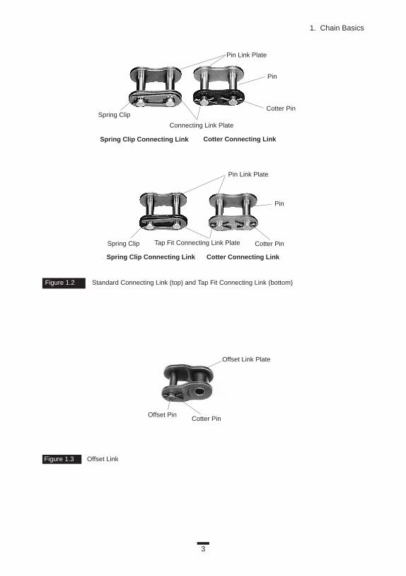
Connecting Link This is the ordinary type of connecting link. The pin and link plate are slip
fit in the connecting link for ease of assembly. This type of connecting link is20 percent lower in fatigue strength than the chain itself. There are also somespecial connecting links which have the same strength as the chain itself. (SeeFigure 1.2.)Tap Fit Connecting Link
In this link, the pin and the tap fit connecting link plate are press fit. It hasfatigue strength almost equal to that of the chain itself. (See Figure 1.2.)Offset Link
An offset link is used when an odd number of chain links is required. It is35 percent lower in fatigue strength than the chain itself. The pin and twoplates are slip fit. There is also a two-pitch offset link available that has afatigue strength as great as the chain itself. (See Figure 1.3.)
Figure 1.1 The Basic Components of Transmission Chain
Offset Pin
Slip Fit
Slip Fit
Press Fit
Press Fit Press Fit
Bushing
Pin
Connecting Link Plate
Width Between
Roller Link Plates
Cotter Pin
Offset Link
Connecting Link
Roller Chain
Pitch
Roller Diameter
Pin Link
Roller Link
Spring Clip
Roller Link PlatePin Link Plate
Roller
3
1. Chain Basics
Figure 1.2 Standard Connecting Link (top) and Tap Fit Connecting Link (bottom)
Figure 1.3 Offset Link
Pin Link Plate
Pin
Cotter PinSpring Clip
Connecting Link Plate
Cotter Connecting LinkSpring Clip Connecting Link
Spring Clip Connecting Link
Pin Link Plate
Pin
Cotter Pin
Cotter Pin
Offset Link Plate
Offset Pin
Spring Clip Tap Fit Connecting Link Plate
Cotter Connecting Link

1.1.2 Basic Structure of Small Pitch Conveyor ChainThe basic structure is the same as that of power transmission chain. Figure
1.4 shows a single pitch conveyor chain. The double pitch type in Figure 1.5has an outer plate and an inner plate of the same height, but often has a rollerwith a larger diameter. Usually, an attachment is used with this chain.
1.1.3 Basic Structure of Large Pitch Conveyor Chain—Engineering ClassLarge pitch conveyor chain has the same basic structure as double pitch con-
veyor chain (Figure 1.5), but there are some differences. Large pitch conveyorchain (Figure 1.6) has a headed pin, sometimes a flanged roller (F-roller), andusually does not use a riveted pin. Large pitch conveyor chain is also calledengineering class chain.
1.1.4 Functions of Chain Parts
PlateThe plate is the component that bears the tension placed on the chain.
Usually this is a repeated loading, sometimes accompanied by shock.Therefore, the plate must have not only great static tensile strength, but alsomust hold up to the dynamic forces of load and shock. Furthermore, the platemust meet environmental resistance requirements (for example, corrosion,abrasion, etc.).
4
Basics
Figure 1.5 Basic Structure of Double Pitch Conveyor Chain with A-2 Attachment
Figure 1.4 Single Pitch Conveyor Chain with K-1 Attachment
Pin
Connecting Link Plate
Roller
Attachment Roller Link Plate
Attachment Pin Link Plate
Cotter Pin
Roller Link Plate
Pin Link Plate
Bushing

5
1. Chain Basics
PinThe pin is subject to shearing and bending forces transmitted by the plate. At
the same time, it forms a load-bearing part, together with the bushing, whenthe chain flexes during sprocket engagement. Therefore, the pin needs hightensile and shear strength, resistance to bending, and also must have sufficientendurance against shock and wear.Bushing
The bushing is subject to shearing and bending stresses transmitted by the plate and roller, and also gets shock loads when the chain engages thesprocket.
In addition, when the chain articulates, the inner surface forms a load-bear-ing part together with the pin. The outer surface also forms a load-bearingpart with the roller’s inner surface when the roller rotates on the rail orengages the sprocket. Therefore, it must have great tensile strength againstshearing and be resistant to dynamic shock and wear.Roller
The roller is subject to impact load as it strikes the sprocket teeth during thechain engagement with the sprocket. After engagement, the roller changes itspoint of contact and balance. It is held between the sprocket teeth and bush-ing, and moves on the tooth face while receiving a compression load.
Figure 1.6 Basic Structure of Large Pitch Conveyor Chain
Pin
Pin Link Plate
Press Fit
Slip Fit
Bushing
Press Fit
Press Fit
Press Fit
Pin Link
Roller Link
Roller Link
Pin Link
Pitch
Roller Dia.
Width Between
Roller Link Plates
Roller Link Plate
Pin LinkPlate
(Flat Hole)
T-Pin
Slip Fit
Attachment

6
Basics
Furthermore, the roller’s inner surface constitutes a bearing part togetherwith the bushing’s outer surface when the roller rotates on the rail. Therefore,it must be resistant to wear and still have strength against shock, fatigue, andcompression.Cotter Pin, Spring Clip, T-Pin
These are the parts that prevent the outer plate from falling off the pin at thepoint of connection. They may wear out during high-speed operation, there-fore, for this application, these parts require heat treatment.
1.2 ADVANTAGES AND DISADVANTAGES OF CHAIN FOR POWER TRANSMISSION AND CONVEYORS
1.2.1 Power Transmission UsesPower transmission machines use either chains, gears, or belts. Table 1.1
provides a comparison of typical applications.Usually, chain is an economical part of power transmission machines for
low speeds and large loads. However, it is also possible to use chain in high-speed conditions like automobile engine camshaft drives. This is accomplishedby devising a method of operation and lubrication.
Basically, there are lower limits of fatigue strength in the gear and the chain,but not in the belt. Furthermore, if a gear tooth breaks, the gear will stop atthe next tooth. Therefore, the order is gear > chain > belt in the aspect of reli-ability.
In most cases:(1) An increase in gear noise indicates that the end of the service life is
near.(2) You will know that the chain is almost at the end of its life by wear
elongation or an increase in vibration caused by wear elongation.(3) It is difficult to detect toothed-belt life without stopping the machine
and inspecting the belt carefully.It is possible to decrease gear noise by adjusting the gears precisely or by
adapting the drive to a helical or double helical gear. Both of these are expen-sive, and thrust load may occur with the use of helical gears.
Chain is more suitable to long-term continuous running and power trans-mission with limited torque fluctuation. Gears are more fit to reversing or intermittent drives.
The greater the shaft center distance, the more practical the use of chainand belt, rather than gears.

Table 1.1 Comparison Table
Type Roller Chain Tooth Belt V Belt Spur Gear
Sychronization
TransmissionEfficiency
Anti-Shock
Noise/Vibration
SurroundingCondition Avoid Water, Dust Avoid Heat, Oil, Water, Dust Avoid Heat, Oil, Water, Dust Avoid Water, Dust
Space
Saving
Lubrication
Required No Lube No Lube Required
Layout Flexibilty
Excess Loadonto Bearing
High SpeedLow Load
Low SpeedHigh Load Compact Heavy Pulley Wider Pulley Less Durability Due to Less Engagement
Generally, under the same transmission conditions, the cost of toothed beltsand pulleys is much higher than the cost of chains and sprockets.
See the following features and points of notice about roller chain transmission.
Features of Chain Drives:1. Speed reduction/increase of up to seven to one can be easily
accommodated.2. Chain can accommodate long shaft-center distances (less than 4 m),
and is more versatile.3. It is possible to use chain with multiple shafts or drives with both sides
of the chain.4. Standardization of chains under the American National Standards Institute
(ANSI), the International Standardization Organization (ISO), and the Japanese Industrial Standards (JIS) allow ease of selection.
5. It is easy to cut and connect chains.6. The sprocket diameter for a chain system may be smaller than a belt
pulley, while transmitting the same torque.7. Sprockets are subject to less wear than gears because sprockets distribute
the loading over their many teeth.
Points of Notice:1. Chain has a speed variation, called chordal action, which is caused by
the polygonal effect of the sprockets.2. Chain needs lubrication.3. Chain wears and elongates.4. Chain is weak when subjected to loads from the side. It needs proper
alignment.7
1. Chain Basics
Excellent Good Fair Poor

1.2.2 Conveyance UsesConveyor systems use either chains, belts, or rollers, depending on the
application. The general guidelines for suitability are shown in Table 1.2, anddiscussed in Basics Section 1.2.1.
Belt conveyors are most suitable for large-volume movement of bulk materi-als. Except for this situation, chains, belts, and rollers are generally difficult tocompare in terms of capacity, speed, or distance of conveyance of unit materials.
NOTE: In this discussion, bulk materials refer to items like grain orcement that may shift during conveyance. Unit materials, such asautomobiles or cardboard, are stable when conveyed.
1.3 SPROCKETSThe chain converts rotational power to pulling power, or pulling power to
rotational power, by engaging with the sprocket.The sprocket looks like a gear but differs in three important ways:1. Sprockets have many engaging teeth; gears usually have only one or
two. 2. The teeth of a gear touch and slip against each other; there is basically
no slippage in a sprocket.3. The shape of the teeth are different in gears and sprockets.
Table 1.2
Conveyor Type Chain Belt Roller
Bulk Handling
Unit Handling
Only for light conveyor
Dust in Conveying Bulky Goods ( for closed conveyor) ——
Space Required Small Large Large
8
Basics
Figure 1.7 Types of Sprockets
Excellent Good Poor

9
Figure 2.1 Typical Chain in Tensile Test Figure 2.2 Stress-Strain Graph
2. CHAIN DYNAMICSA study of phenomena that occur during chain use.
2.1 CHAINS UNDER TENSIONA chain can transmit tension, but usually cannot transmit pushing forces.
There are actually a few special chains that can push, but this discussionfocuses on tension. In the following section we will explain how the chainacts under tension.
2.1.1 Elastic Stretch, Plastic Deformation, and Breakage
Tensile Strength How will the chain behave when it is subjected to tensile loading? There is
a standardized test to determine the tensile strength of a chain. Here’s how it works: The manufacturer takes a new, five-link-or-longer power transmis-sion chain and firmly affixes both ends to the jigs (Figure 2.1). Now a load or tension is applied and measurements are taken until the chain breaks (JIS B 1801-1990).
Chain Elongation As a chain is subjected to increasing stress or load, it becomes longer.
This relationship can be graphed (Figure 2.2). The vertical axis shows increas-ing stress or load, and the horizontal axis shows increasing strain or elonga-tion. In this stress-strain graph, each point represents the following:
O-A: elastic regionA: limit of proportionality for chains; there is not an
obvious declining point, as in mild steelA-C: plastic deformation
B: maximum tension pointC: actual breakage
Elongation
Load
O

10
Basics
Reporting Tensile Strength Point B, shown in Figure 2.2, the maximum tension point, is also called the
ultimate tensile strength. In some cases, point B will come at the same time aspoint C. After breaking a number of chains, a tensile strength graph shows anormal distribution (Figure 2.3).
The average load in Figure 2.3 is called the average tensile strength, and thelowest value, which is determined after statistically examining the results, iscalled the minimum tensile strength. JIS (Japanese Industrial Standard) alsoregulates minimum tensile strength, but it is much lower than any manufactur-er’s tensile strength listed in their catalogs.
“Maximum allowable load,” shown in some manufacturer’s catalogs, isbased on the fatigue limit (see Basics Section 2.2.2). This value is much lowerthan point A. Furthermore, in the case of power transmission chain, point A isusually 70 percent of the ultimate tensile strength (point B). If the chainreceives greater tension than point A, plastic deformation will occur, and thechain will be nonfunctional.
Using Tensile Strength InformationFor the sake of safety, you should never subject chains to tension greater
than half the average tensile strength—not even once. If the chain is inadver-tently loaded that high, you should change the whole chain set. If the chain isrepeatedly subjected to loads greater than the maximum allowable load,fatigue failure may result.
When you see tensile strength graphs or stress-strain graphs, you should beaware of the following facts:
1. Every manufacturer shows the average tensile strength in its catalog, butit is not unusual to find that the value listed may have been developedwith sales in mind. Therefore, when comparing chains from differentmanufacturers, check the minimum tensile strength.
Figure 2.3 Tensile Strength
JIS Tensile StrengthMin. Tensile Strength
Avg.Tensile Strength
Tensile Strength
Fre
quen
cy

11
2. Chain Dynamics
2. In addition to the tensile strength, the most important fact about a stress-strain graph is the value of stretch at the time of breakage. If the chain’stensile strength is higher and the capacity to stretch is greater, the chaincan absorb more energy before it breaks. This means the chain won’t beeasily broken even if it receives unexpected shock load. (In Figure 2.2,the cross-hatched area is the value of energy that the chain can absorbbefore it breaks.)
Elastic ElongationAnother important characteristic in practice is how much elastic elongation
the chain will undergo when it is subjected to tension. When you use chainsfor elevators on stage, if there is a difference between the stage floor and theelevator platform, the dancers will trip on it. In an elevator parking garage, itis necessary to lower cars down to the entrance within a small difference inthe level. Therefore, it is important to anticipate how long the chain’s elasticstretch will be. Figure 2.4 shows elasticity/stretch for power transmission rollerchains.
Please contact the individual manufacturers about small and large pitch con-veyor chains.
Figure 2.4 Elastic Elongation on Roller Chain
Load Lo
ad
Max. Allowable Load
Elongation (mm/m) Elongation (mm/m)
Max. Allowable Load

12
Basics
2.1.2 Engagement with SprocketsAlthough chains are sometimes pushed and pulled at either end by cylin-
ders, chains are usually driven by wrapping them on sprockets. In the follow-ing section, we explain the relation between sprockets and chains whenpower is transmitted by sprockets.
1. Back tensionFirst, let us explain the relationship between flat belts and pulleys. Figure
2.5 shows a rendition of a flat belt drive. The circle at the top is a pulley, andthe belt hangs down from each side. When the pulley is fixed and the left sideof the belt is loaded with tension (T0), the force needed to pull the belt downto the right side will be:
T1 = T0 3 eµu
For example, T0 = 100 N: the coefficient of friction between the belt andpulley, µ = 0.3; the wrap angle u = π (180˚).
T1 = T0 3 2.566 = 256.6 N
In brief, when you use a flat belt in this situation, you can get 256.6 N ofdrive power only when there is 100 N of back tension. For elements withoutteeth such as flat belts or ropes, the way to get more drive power is toincrease the coefficient of friction or wrapping angle. If a substance, likegrease or oil, which decreases the coefficient of friction, gets onto the contactsurface, the belt cannot deliver the required tension.
In the chain’s case, sprocket teeth hold the chain roller. If the sprocket toothconfiguration is square, as in Figure 2.6, the direction of the tooth’s reactiveforce is opposite the chain’s tension, and only one tooth will receive all thechain’s tension. Therefore, the chain will work without back tension.
Figure 2.5 Flat Belt Drive Figure 2.6 Simplified Roller/Tooth Forces
Chain Roller
Roller
Tooth Force
T0
T1

13
2. Chain Dynamics
But actually, sprocket teeth need some inclination so that the teeth canengage and slip off of the roller. The balance of forces that exist around theroller are shown in Figure 2.7, and it is easy to calculate the required backtension.
For example, assume a coefficient of friction µ = 0, and you can calculatethe back tension (Tk) that is needed at sprocket tooth number k with this for-mula:
Tk = T0 3sin ø k-1
sin(ø + 2b)Where:
Tk= back tension at tooth kT0 = chain tensionø = sprocket minimum pressure angle 17 – 64/N(˚)N = number of teeth
2b = sprocket tooth angle (360/N)k = the number of engaged teeth (angle of wrap 3 N/360); round down
to the nearest whole number to be safe
By this formula, if the chain is wrapped halfway around the sprocket, theback tension at sprocket tooth number six is only 0.96 N. This is 1 percent ofthe amount of a flat belt. Using chains and sprockets, the required back tensionis much lower than a flat belt.
Now let’s compare chains and sprockets with a toothed-belt back tension.Although in toothed belts the allowable tension can differ with the number
of pulley teeth and the revolutions per minute (rpm), the general recommen-dation is to use 1/3.5 of the allowable tension as the back tension (F). This isshown in Figure 2.8. Therefore, our 257 N force will require 257/3.5 = 73 N ofback tension.
Both toothed belts and chains engage by means of teeth, but chain’s backtension is only 1/75 that of toothed belts.
Figure 2.7 The Balance of Forces Around the Roller
Tooth Force
Link Tension
Frictional Tooth Force
Chain Tension
Pressure Angle

14
Basics
2. Chain wear and jumping sprocket teethThe key factor causing chain to jump sprocket teeth is chain wear elongation
(see Basics Section 2.2.4). Because of wear elongation, the chain creeps up onthe sprocket teeth until it starts jumping sprocket teeth and can no longerengage with the sprocket. Figure 2.9 shows sprocket tooth shape and posi-tions of engagement. Figure 2.10 shows the engagement of a sprocket with anelongated chain.
In Figure 2.9 there are three sections on the sprocket tooth face:a: Bottom curve of tooth, where the roller falls into place;b: Working curve, where the roller and the sprocket are working together;c: Where the tooth can guide the roller but can’t transmit tension. If the
roller, which should transmit tension, only engages with C, it causes jumped sprocket teeth.
The chain’s wear elongation limit varies according to the number of sprocketteeth and their shape, as shown in Figure 2.11. Upon calculation, we see thatsprockets with large numbers of teeth are very limited in stretch percentage.Smaller sprockets are limited by other harmful effects, such as high vibrationand decreasing strength; therefore, in the case of less than 60 teeth, the stretchlimit ratio is limited to 1.5 percent (in transmission chain).
Figure 2.8 Back Tension on a Toothed Belt
Figure 2.9 Sprocket Tooth Shape and Positions of Engagement
Figure 2.10 The Engagement Between a Sprocket and an Elongated Chain

In conveyor chains, in which the number of working teeth in sprockets isless than transmission chains, the stretch ratio is limited to 2 percent. Largepitch conveyor chains use a straight line in place of curve B in the sprockettooth face.
2.2 CHAIN DRIVE IN ACTIONLet’s study the case of an endless chain rotating on two sprockets
(Figure 2.12).
2.2.1 Chordal ActionYou will find that the position in which the chain and the sprockets engage
fluctuates, and the chain vibrates along with this fluctuation. Even with thesame chain, if you increase the number of teeth in the sprockets (change tolarger diameter), vibration will be reduced. Decrease the number of teeth inthe sprockets and vibration will increase.
This is because there is a pitch length in chains, and they can only bend atthe pitch point. In Figure 2.13, the height of engagement (the radius from thecenter of the sprocket) differs when the chain engages in a tangent positionand when it engages in a chord.
15
2. Chain Dynamics
Figure 2.11 Elongation Versus the Number of Sprocket Teeth
Figure 2.12 An Endless Chain Rotating Around Two Sprockets
Allo
wab
leE
long
atio
n(%
)
Number of Teeth in Sprocket

16
Basics
Figure 2.13 The Height of Engagement
Figure 2.14 Speed Variation Versus the Number of Sprocket Teeth
Therefore, even when the sprockets rotate at the same speed, the chainspeed is not steady according to a ratio of the sprocket radius (with chordalaction). Chordal action is based on the number of teeth in the sprockets:
Ratio of speed change = (Vmax – Vmin) / Vmax = 1 – cos (180˚/N)
Figure 2.14 shows the result. In addition to the number of teeth, if the shaftcenter distance is a common multiple of the chain pitch, chordal action issmall. On the other hand, if shaft center distance is a multiple of chain pitch +0.5 pitch, chordal action increases. Manufacturing and alignment errors canalso impact chordal action.
In a flat-belt power transmission machine, if the thickness and bending elas-ticity of the belt are regular, there is no chordal action. But in toothed-belt sys-tems, chordal action occurs by circle and chord, the same as chains. Generallythis effect is less than 0.6 percent, but when combined with the deflection ofthe pulley center and errors of belt pitch or pulley pitch, it can amount to 2 to3 percent.
Number of Teeth in Sprocket
Spe
edV
aria
tion
(%)
Vmax – Vmin
Vmax
Maximum Chain SpeedVmax = Rv
Chordal Rise
Minimum Chain SpeedVmin = rv
17
2. Chain Dynamics
Figure 2.16 Chain Load with the Addition of Resistance
Figure 2.15 A Typical Chain Drive with the Driving Side on the Left
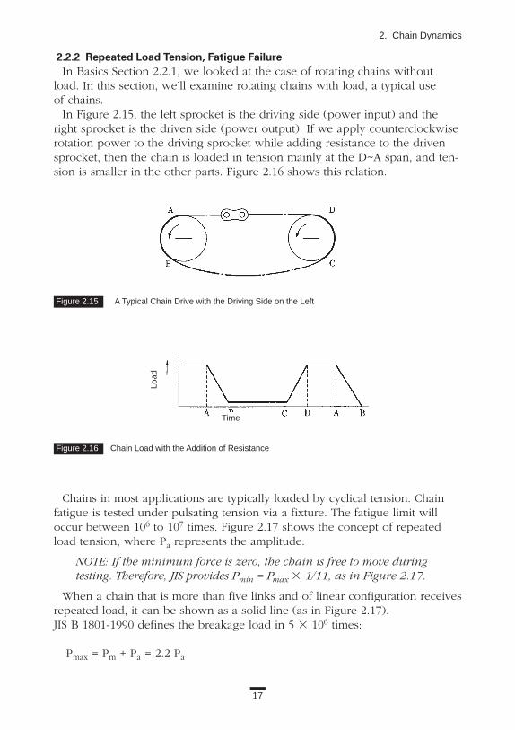
2.2.2 Repeated Load Tension, Fatigue FailureIn Basics Section 2.2.1, we looked at the case of rotating chains without
load. In this section, we’ll examine rotating chains with load, a typical use of chains.
In Figure 2.15, the left sprocket is the driving side (power input) and theright sprocket is the driven side (power output). If we apply counterclockwiserotation power to the driving sprocket while adding resistance to the drivensprocket, then the chain is loaded in tension mainly at the D~A span, and ten-sion is smaller in the other parts. Figure 2.16 shows this relation.
Time
Load
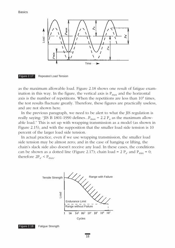
Chains in most applications are typically loaded by cyclical tension. Chainfatigue is tested under pulsating tension via a fixture. The fatigue limit willoccur between 106 to 107 times. Figure 2.17 shows the concept of repeatedload tension, where Pa represents the amplitude.
NOTE: If the minimum force is zero, the chain is free to move duringtesting. Therefore, JIS provides Pmin = Pmax 3 1/11, as in Figure 2.17.
When a chain that is more than five links and of linear configuration receivesrepeated load, it can be shown as a solid line (as in Figure 2.17). JIS B 1801-1990 defines the breakage load in 5 3 106 times:
Pmax = Pm + Pa = 2.2 Pa
18
Basics
as the maximum allowable load. Figure 2.18 shows one result of fatigue exam-ination in this way. In the figure, the vertical axis is Pmax and the horizontalaxis is the number of repetitions. When the repetitions are less than 104 times,the test results fluctuate greatly. Therefore, these figures are practically useless,and are not shown here.
In the previous paragraph, we need to be alert to what the JIS regulation isreally saying: “JIS B 1801-1990 defines...Pmax = 2.2 Pa as the maximum allow-able load.” This is set up with wrapping transmission as a model (as shown inFigure 2.15), and with the supposition that the smaller load side tension is 10percent of the larger load side tension.
In actual practice, even if we use wrapping transmission, the smaller loadside tension may be almost zero; and in the case of hanging or lifting, thechain’s slack side also doesn’t receive any load. In these cases, the conditionscan be shown as a dotted line (Figure 2.17); chain load = 2 Pa' and Pmin = 0;therefore 2Pa' < Pmax.
Figure 2.18 Fatigue Strength
Range with Failure
Endurance Limit
Range without Failure
Tensile Strength
Load
Cycles
Figure 2.17 Repeated Load Tension
Time
Load

19
2. Chain Dynamics
If you follow the JIS definition of Pmax as maximum allowable load and youchoose a chain on the higher limits of the scale, the chain might not stand up to those strength requirements. In some situations a fatigue failure might occureven though it met the JIS requirement for maximum allowable load.
This is the reason that some manufacturers, such as Tsubaki, use 2Pa as the maximum allowable load; or some manufacturers calculate 2Pa under the situation of Pmin = 0 and show this in their catalog. In the latter method, the 2Pa'value is larger than the value of the former method. The maximum allowableload value of the JIS method is 10 percent greater than the former method of 2Pa.
In addition, some manufacturers, including Tsubaki, establish a fatigue limitfor strength at 107 cycles. JIS sets a fatigue strength at 5 3 106 cycles.
Including the JIS scale, there are more than three ways of expressing thesame information in manufacturers’ catalogs. Therefore, you should not makea final determination about a chain’s functions simply by depending on infor-mation found in different catalogs. Consider a manufacturer’s reliability bychecking whether they have their own fatigue-testing equipment. Ask if theyshow fatigue limit data in their catalogs. The quality guarantee system of ISO9000 series is checked by third parties (instead of users) to gauge whether ornot their system of quality guarantee is adequate. It would be safe to choosemanufacturers who are ISO-9000-series certified.
2.2.3 Transmission Capability of Drive ChainsWe have derived fatigue limits by testing. But just as you can’t judge a per-
son by examination alone, so we must also check whether the results of ourtests can be put to practical use. Some questions remain:
1. The chain’s fatigue limit (see Basics Section 2.2.2) is tested in a linear configuration (Figure 2.1). But in wrapping transmission, the chain is engaging with the sprocket. Is there any difference between these two?
2. A new roller chain is used. Is there any decrease in the strength of a usedchain?
3. Do connecting links or offset links have the same strength? To answer these questions, a number of experiments and investigations
were done. The following are the findings.
2.2.3.1 Difference Between Linear Tension and WrappingWhen the chain engages the sprocket, the chain collides with the sprocket
tooth surfaces. The transmission capability is limited by the roller or bushingbreakage during collision.

20
Basics
As it wraps on the sprocket and rotates, the chain receives centrifugal force.The faster the speed of rotation, the larger the centrifugal force becomes.Additionally, the pin and the bushing are also subject to tension. There is alimit to their bearing function.
2.2.3.2 Effect of Normal Chain Wear on Fatigue StrengthWhen a chain is operating, the outer surface of the pin and inner surface of
the bushing rub against one another, wearing little by little. (Proper lubricationreduces the amount of wear but does not eliminate it.)
The problem is the wear of the pin. As the surface of the pin is reduced, therigidity of the pin decreases and eventually fatigue failure may result. Thequestion is how much wear is acceptable and at what point should you beconcerned.
Testing shows that when wear elongation is less than or equal to 1.5 percentfor transmission chain, or less than or equal to 2 percent for conveyor chain,there is almost no risk of fatigue failure.
NOTE: This replacment limit applies to situations in which every pinand bushing wears equally. If one part is subject to greater wear, thesystem should be examined and repaired. Chains should be replacedat the same time.
In practical terms, the most important consequence of deterioration is adecrease in the fatigue strength by environmental factors. This problem will bediscussed in Basics Section 5.4.
2.2.3.3 Strength Differences Between Chain and the Connecting Links and Offset Links
The individual connecting links and offset links have lower fatigue strength thanthe chain itself. Therefore, you have to consider the strength-decrease ratio shownin Table 2.1. The strength-decrease ratio differs from manufacturer to manufactur-er, so it is important to get specific information from each manufacturer.
If you use chain with loads that are almost the same as the maximum allow-able load, you should avoid using offset links. Use tap fit connecting links,which are stronger than standard connecting links. In some cases, you canorder chains in an endless configuration (see NOTE on next page).
Table 2.1 Strength Reduction of Connecting Links and Offset Links
Reduction RatioType Against Maximum Allowable LoadStandard Connecting Link 0 ~ 20%Tap Fit Connecting Link No reductionOffset Link 35%Two-Pitch Offset Link 0 ~ 25%

21
2. Chain Dynamics
NOTE: Endless configuration: Manufacturers create connecting com-ponents that are as strong as the chain’s other parts by riveting or otherfactory processes. The chain is assembled and delivered as an endlessconfiguration.
The transmission-ability graph, which is sometimes called a “tent curve”because of its shape, includes the result of the three points covered above.This graph is an important tool when making chain decisions. Figure 2.19illustrates the concept of a tent curve.
In Figure 2.19, Line O-A is decided according to the chain’s allowable ten-sion, which includes the fatigue strength of the connecting or offset links, aswell as the centrifugal force in high-speed rotation. Line B-C is decided bybreakage limit of the bushing and roller. In this kind of breakage of the bush-ing and roller, there is no fatigue limit as there is with the link plates.Therefore, it is shown within 15,000 hours of strength-in-limited-duration. LineD-E is decided by the bearing function of the pin and the bushing.
The range defined within these three lines (O-A, B-C, and D-E) is the usablerange. When the chain is used at low speeds, it is limited by line O-A, thefatigue limit. The conditions of the tent curve shown are:
a. Two-shaft wrapping transmission with 100 links of chain.b. Duration of 15,000 hours work.c. Under the Additional Operating Conditions (1 through 5 shown below).
Additional Operating Conditions1. The chain operates in an indoor environment of -10˚C to 60˚C,
and there is no abrasive dust.2. There are no effects from corrosive gas or high humidity.3. The two driving shafts are parallel with each other and adjusted properly.4. Lubrication is applied as recommended in the catalog.5. The transmission is subject to only small fluctuations in load.
Figure 2.19 A Transmission-Ability Graph (Tent Curve)
Roller-Bushing Impact
Link Plate Failure
Galling
Small Sprocket (rpm)
Hor
sepo
wer
(kW
)
O

2.2.4 Wear of Working PartsIn Basics Section 2.2.3.2, we discussed the effects of pin wear. When a chain
is operating, the outer surface of the pin and inner surface of the bushing rubagainst one another, wearing little by little.
When a chain is operating, obviously other parts are also moving and wear-ing. For example, the outer surface of the bushing and inner surface of theroller move against one another. In the case of transmission chain, the rollerand bushing wear is less than that of the pin and the inner surface of thebushing because the chance of rubbing is generally smaller. Also, it is easier toapply lubrication between the bushing and roller.
The progress of pin-bushing wear is shown in Figure 2.20, in which the hori-zontal axis is the working hours and the vertical axis is the wear elongation(percent of chain length).
In Figure 2.20, O-A is called “initial wear.” At first the wear progresses rapid-ly, but its ratio is less than 0.1 percent and usually it will cease within 20 hoursof continuous operation. A-B is “normal wear.” Its progress is slow. B-C is“extreme wear.” The limit of “allowable wear” (the end of its useful life) willbe reached during this stage (1.5 to 2.0 percent).
The solid line reflects a case of using chain with working parts that werelubricated in the factory, but were not lubricated again. If you lubricate regu-larly, the pin and the bushing continue to exhibit normal wear (reflected bythe dotted line), and eventually run out their useful life.
If you remove all the lubricants with solvents, the wear progresses along anearly straight line, and the life of the chain is shortened. This is shown by thedashed line.
The factors that affect chain wear are very complicated. There are many con-siderations, such as lubrication, assembly accuracy, condition of producedparts, and the method of producing parts; therefore, wear value can’t be great-ly improved by merely changing one factor.
22
Basics
Figure 2.20 Pin-Bushing Wear During Operation
Running Time
Elo
ngat
ion
(%)
OA
B
C

In transmission chain, JIS B 1801-1990 regulates the surface hardness of thepin, the bushing, and the roller (as shown in Table 2.2) to meet the multiplerequirements for wear resistance and shock resistance.
2.2.5 Noise and VibrationWhen the chain engages the sprockets, it will definitely make noise
(Figure 2.21). This is caused by several factors:1. The chain roller strikes the sprocket tooth bottom.2. There is space between the roller and the bushing; the roller makes noise
by its elastic vibration (in the case of thin rollers, like S-roller).3. Sprockets vibrate.4. The fluid held between each part (usually air or lubrication oil)
makes shock sounds.
Take for example, an RS80 transmission roller chain and a sprocket with 16teeth operating at a speed of 123 rpm. (The chain speed is 50 m/min.) In thiscase, the noise at a point 30 cm from the sprocket will be: with no lubrication,65 dB (A); with lubrication, 57 dB (A).
According to the data given above, the noise made by the chain engagingthe sprocket can be predicted. Please contact the manufacturer.
There are some steps you can take to lessen the noise level. a. Decrease striking energy:
• Use a sprocket with many teeth. This reduces the impact velocitywhile maintaining the same chain speed.
• Operate the chain at slower speeds.• Use smaller chain to decrease the chain’s weight.
23
2. Chain Dynamics
Figure 2.21 Noise Occurs when the Chain Engages the Sprocket
Table 2.2. Surface Hardness of Pin, Bushing, and Roller
Component HV HRCPin 450 or greater 45 or greaterBushing 450 or greater 45 or greaterRoller 390 or greater 40 or greater

24
Basics
b. Buffer the effects of the impacting parts:• Lubricate at the bottom of the sprocket tooth and the gap between
the bushing and the roller.• Use specially engineered plastic rollers. (This will also decrease
transmission capability. There is virtually no decrease in sound if you change to an engineered plastic sprocket.)
If we compare noise from chains and sprockets with other transmission machine parts like belt and pulley or toothed belt and pulley, we find:
a. Belt noise is less than the other two. Compared to a flat belt, a toothed belt makes a high frequency noise during high speed.
b. Usually, chain transmission is smoother than gear transmission. The chain also differs in that there is no increase in noise level as it wears and elongates during use.
2.3 CHARACTERISTIC PHENOMENA IN CONVEYOR CHAINUntil now, we have primarily been explaining matters that apply specifically
to power transmission chains. However, there are some different problems thatoccur when using conveyor chain.
2.3.1 Coefficient of FrictionThe tension of transmission chain is calculated by dividing the transmitted
power (indicated as kW or horsepower) by the chain speed and multiplying byan adequate coefficient. But in a fixed-speed, horizontal conveyor, tension isdecided by those factors shown below:
1. The coefficient of friction between the chain and the rail when conveyed objects are placed on the chain.
2. The coefficient of friction between conveyed objects and the rail when conveyed objects are held on the rail and pushed by the chain.
NOTE: There are two types of tension: the first occurs when conveyedobjects are moving at a fixed speed, and the second is inertial effectsthat occur when starting and stopping the machine. We will only talkabout the former in this section, and the latter in Basics Section 2.3.2.
Figure 2.22 Tension on a Horizontal Conveyor

Table 2.3 Friction Coefficients for Top Plate and Guide Rails
Friction CoefficientTop Plate Material Guide Rail Material Unlubricated LubricatedStainless Steel or Steel Stainless Steel or Steel 0.35 0.20Stainless Steel or Steel UHMW 0.25 0.15Engineered Plastic Stainless Steel or Steel 0.25 0.15Engineered Plastic UHMW 0.25 0.12Engineered Plastic (Low Friction) Stainless Steel or Steel 0.17 0.12Engineered Plastic (Low Friction) UHMW 0.18 0.12
25
2. Chain Dynamics
The tension (T) in a horizontal conveyor, like that in Figure 2.22, is basically calculated by this formula:
T = M1 3 g 3 f1 3 1.1 + M1 3 g 3 f2 + M2 3 g 3 f3Where:
T = total chain tensionM1 = weight of the chain, etc. M2 = weight of conveyed objectsf1 = coefficient of friction when chain, etc., are returningf2 = coefficient of friction when chain, etc., are conveyingf3 = coefficient of friction when conveyed objects are movingg = gravitational constant
1.1 = sprocket losses due to directional changes of the chain
NOTE: “chain, etc.,” in the above formula includes chain and the partsmoving with the chain, such as attachments and slats.
In this formula, a coefficient of friction is multiplied by every term in theequation. Therefore, if the coefficient of friction is high, the tension increasesand larger chain is required. Also, the necessary motor power, which is calculat-ed as tension 3 speed 3 coefficient, increases. A more powerful motor is need-ed when the coefficient of friction is high.
Reduce the coefficient of friction and you can reduce the tension, too. Thisallows you to choose a more economical chain and motor, and decrease the ini-tial and running costs for conveyor equipment.
The chain’s coefficient of friction differs by type of chain, by material, and bytype of roller; it is shown in the manufacturer’s catalog. To illustrate this con-cept, two examples are included. The coefficient of friction for different types oftop chain and guide rails is shown in Table 2.3. The coefficient of friction whenlarge R-roller chain rotates on rails (rail material: steel) is shown in Table 2.4.
Table 2.4 Friction Coefficients for Different Types of Rollers
Friction CoefficientChain Type Roller Type Unlubricated LubricatedRF Double Pitch Chain Steel 0.12 0.08
Engineered Plastic 0.08 —Large Pitch Conveyor Chain Steel 0.13 ~ 0.15 0.08
Engineered Plastic 0.08 —Bearing Roller 0.03 —
26
Basics
Technology can help you reduce the coefficient of friction. Some of thenewest chains (for example, low-friction top chain, engineered plastic rollerchain, and bearing roller chain) can achieve low coefficients of friction with-out lubrication. Other chains would have to be lubricated to achieve thesecoefficients. In some instances, these new chains achieve dramatically lowercoefficients of friction. That means you can save maintenance time, money,and energy at your facility.
2.3.2 Dynamic Tension of Starting and StoppingConveyor chain accelerates when it changes from stop mode to operational
speeds, and decelerates when it changes from operational speeds to stopmodes. Therefore, a dynamic tension resulting from inertia affects the convey-or chain, and it is added to “the tension produced when conveyed objects aremoving at fixed speed,” which is discussed in Basics Section 2.3.1. You mustconsider dynamic tension caused by inertia, especially in the following cases:
1. Starting and stopping chains frequently, such as intermittent use with indexing equipment.
2. Starting and stopping in very short time spans.3. When chains in motion suddenly receive stationary objects to convey.
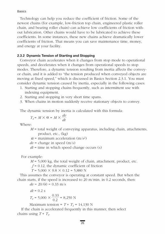
The dynamic tension by inertia is calculated with this formula:
T1 = M 3 α = M 3dvdt
Where:M = total weight of conveying apparatus, including chain, attachments,
product, etc., (kg)α = maximum acceleration (m/s2)
dv = change in speed (m/s)dt = time in which speed change occurs (s)
For example: M = 5,000 kg, the total weight of chain, attachment, product, etc.f = 0.12, the dynamic coefficient of frictionT = 5,000 3 9.8 3 0.12 = 5,880 N
This assumes the conveyor is operating at constant speed. But when thechain starts, if the speed is increased to 20 m/min. in 0.2 seconds, then:
dv = 20/60 = 0.33 m/s
dt = 0.2 s
T1 = 5,000 30.33
= 8,250 N0.2
Maximum tension = T + T1 = 14,130 NIf the chain is accelerated frequently in this manner, then select
chains using T + T1.

27
2. Chain Dynamics
2.3.3 Wear Between Rollers and BushingsDuring the operation of conveyor chains, rollers receive some additional
forces, which are shown in Figure 2.23 and listed below: 1. The weight of conveyed objects when they are put directly on the chain.2. The reaction forces when pushing conveyed objects with a dog.3. Directional variation tension when the rail is set in a curved path.
These forces cause wear between rollers and bushings.Some manufacturers publish an “allowable roller load”—a value at which the
wear rate of the roller is comparatively slow. For steel rollers, it is the valuewith lubrication. For engineered plastic rollers and bearing rollers, the valuesshown are without lubrication. Sometimes, engineered plastic rollers may beaffected by speed. Please check the catalogs.
If foreign objects, including conveyed objects, get into the working parts ofthe chain, the catalog values are no longer applicable, even if you are usinglubrication.
There are many conveyed objects that work as lubricants; therefore, it ishard to generalize about the allowable roller loads when there are any foreignobjects that might get into the working parts. Furthermore, the loads on therollers (as shown in points 1 through 3 above), are also applicable to the siderollers and to the resulting wear of pins and side rollers. Make sure you con-sider these factors when setting up a conveyor system.
Figure 2.23 Forces on Conveyor Rollers
Roller Load
Skid Line
Roller Load
Corner RailRoller Load
Roller LoadLoad

28
Basics
2.3.4 Strength of AttachmentsBending and twisting forces can affect the attachments. For the A attach-
ment, which is a common type, the allowable load calculation indicated in cat-alogs is based on the bending strength.
When a tall fixture is added onto the attachment, you must study thestrength of the entire configuration. When the attachment is subject to forcesother than those explained, you also must calculate the twisting forces. If theattachment receives bending forces at the same time, make sure to combinethe bending forces with the twisting forces.
When calculating the strength of attachments such as A-type, K-type, SA-type, and SK-type, which are extensions of a standard steel chain’s plate, usethe values shown below as their ultimate tensile strength, and choose a propersafety factor.
Nonheat-treated plate: 490 MPa (50 kgf/mm2)Heat-treated plate: 1,078 MPa (110 kgf/mm2)
2.3.5 Stick SlipWhen using an extra-long conveyor system (more than 15 m) and slow
chain speed (less than 10 m/min.), you may notice longitudinal vibration inthe line, which is called stick slip, or jerking.
The basis for this phenomenon can be seen in Figure 2.24. Here the coeffi-cient of friction is plotted against the speed of the chain. When operating along conveyor at slow speeds, the coefficient of friction for sliding surfaces (intop chains, between top plates and rails; in R-rollers, between the outer sur-face of the bushing and inner surface of the roller) decreases as speed increas-es. This causes the chain to jerk or stick slip.
Usually, you can’t solve this problem by adding lubrication or by increasingthe number of sprocket teeth. There are, however, things you can do to pre-vent or reduce stick slip:
1. Increase chain speed.
Figure 2.24 How Chain Speed Impacts the Friction Coefficient
Chain Speed
Coe
ffcie
ntof
Fric
tion

29
2. Chain Dynamics
2. Eliminate or decrease the decline in the coefficient of friction by using abearing roller (please consult with manufacturer if the speed is less than 2m/min.), or use a special kind of lubrication oil (Tsubaki special oil, orothers).
3. Increase chain rigidity (AE). A is the chain’s section area, and E is Young’s modulus. To increase AE, use a larger chain. If there are several chains with the same allowable tension, choose the one with the thicker plate.
4. Separate the conveyor into sections and reduce the length of each machine.
If stick slip continues to be a problem, consult the equipment manufacturer.
2.3.6 Relative Differences in Chain’s Total LengthIf you want to achieve a precise positioning of more than two chain lines to
be used in parallel, you can order “matched and tagged” chain. Generally, ifthe conveyor chains are made in the same lots, the relative differences inlength will vary only slightly. Table 2.5 shows the amount of variation for sev-eral types of chain chosen at random from the same production run.
If your specific application requires less variation than those listed in Table2.5, consider matched and tagged chains as an effective solution.
2.3.7 Take-UpConveyor chains need proper tension, which is why take-up is added to a sys-
tem. You have to position take-up where the chain’s tension will be minimal. Ifyou can remove two links from the chain, the adjusting length of take-up is:
L = chain pitch + spare lengthIf you can’t remove links from the chain, use this formula:
L = length of machine 3 0.02 + spare length
In this formula, 0.02 represents the allowable wear value (2 percent). Thereare two portions of the spare length: one is the maximum and minimum rangeof variation in length for new chains; the other portion is the length to loosenthe chain’s connecting link when the chain’s total length has been set as tightas possible. For example: the machine length is 10 m, the length for maximumand minimum range of variation is 0.25 percent, assuming the length neededto connect chain is 25 mm, then:
L = 10,000 3 (0.02 + 0.0025) + 25 = 225 + 25 = 250 (mm)
Table 2.5 Conveyor Chains Chosen at Random from Same Production Lot
Center Distance Matched ToleranceLess than 7 m Less than 3 mm7 ~ 15 m Less than 4 mm15 ~ 22 m Less than 5 mm

30
Basics
If the chain expands and contracts with temperature, the system needssome means to absorb it. When you use a chain in a high-temperature envi-ronment or to convey high-temperature objects, the chain becomes hotterand the length increases at about the same ratio as its coefficient of linearexpansion. When the temperature is between 0˚ and 300˚C, and 1 m of chainis heated by a value of 100˚C, the chain elongates by about 1 mm. If youwant to allow for this elongation with take-up, you must be careful about thefollowing points or the chain may fail:
• In the case of chain temperature increase, adjust take-up after the temperature increase.
• In the case of chain temperature decrease, adjust take-up before the decrease.
In the case of chain temperature change, the take-up should be designed toabsorb the elongation or the contraction of the chain.
If you don’t drive the chain in reverse, it is more convenient to design acatenary section and collect the elongation in that part. In that case, it is alsobeneficial to design a take-up. Figure 2.25 shows an example of a designwith catenary and take-up.
It is very annoying to continuously adjust take-up. Sometimes it is possible touse self-adjusting take-ups by hanging a weight or using a hydraulic powercylinder instead of adjusting the take-up. However, the chain receives addition-al tension by doing this (sometimes the motor capacity is also influenced), sodon’t forget to check the chain strength as well as the motor capacity.
Another point about take-up is that if you drive the chain in reverse whilecarrying objects, the take-up receives the load as if it were a driving part. Inthis situation, you must select and design take-up with consideration for itsstrength.
Figure 2.25 Catenary Take-Up
Driver Sprocket
Take-Up
Roller Catenary Support

31
Table 3.1. Standards for Major Types of Chains1
ANSI ISO JISChain Category Standard Standard StandardPower Transmission Roller Chain ANSI B 29.1M ISO 606 JIS B 1801Power Transmission Bushed Chain ANSI B 29.1M ISO 1395 JIS B 1801Power Transmission Sprocket ANSI B 29.1M ISO 606 JIS B 1802Heavy-Duty Chain ANSI B 29.10M ISO 3512Bicycle Chain ISO 9633 JIS D 9417Motorcycle Chain ISO 10190 JCAS 12
Leaf Chain ANSI B 29.8M ISO 4347 JIS B 1804Double Pitch Conveyor Chain & Sprocket ANSI B 29.4 ISO 1275 JIS B 1803Power Transmission Roller Chain with Attachment ANSI B 29.5 JIS B 1801Conveyor Chain ANSI B 29.15 ISO 1977/1~3 JCAS 22
1 The contents of each standard for a category may vary from group to group. 2 JCAS indicates the Japanese Chain Association Standard.
3. PUBLIC STANDARDS OF CHAINSBecause chain is widely used throughout the world, there are both interna-
tional and domestic standards to guarantee their interchangeability and func-tions. Table 3.1 shows the primary standards.

32
4. HOW TO SELECT CHAINSIn this chapter, we outline the selection process. To choose the right chain,
follow the step-by-step procedure for the type of line you’re running. The firstthing you must determine is the type of application: power transmission orconveyor. The selection process differs for the two applications; see BasicsSections 4.1 and 4.2.
In addition to the procedures described in this book, chain manufacturersusually provide comprehensive selection charts in their catalogs; refer to themanufacturer’s catalog for detailed information.
4.1 TRANSMISSION CHAIN SELECTIONThere are four main uses for transmission chains: power transmission, hang-
ing transmission, shuttle traction, and pin-gear driving. 1. Power transmission. The most frequent application, power transmission
involves an endless chain wrapped on two sprockets. There are two ways to select chains for this use.
For general applications, you can select by power transmission capability(tent curve). This is shown in Figure 4.1.
For slow-speed operation, you can make an economical selection using themaximum allowable tension. Use this method when chain speed is less than50 m/min. and starting frequency is less than five times/day (Figure 4.2).
Figure 4.1 Power Transmission Capability Figure 4.2 Maximum Allowable Load at Slow Speeds (less than 50 m/min.)
Small Sprocket (rpm)Number of Cycles
Tensile Strength
Pow
er
Max. Allowable Load
Load
With Catenary
Without Catenary
kW
1 107

2. Hanging transmission. This design is increasing in popularity. It is used, for example, in parking garage elevators. Sprockets rotate, and conveyed objects can be lifted or suspended at the end of chains. (Figure 4.3).
3. Shuttle traction. (Figure 4.4).4. Pin-gear drive. In this design, the chains are laid straight or in a large
diameter circle and are driven with special tooth form sprockets. This design is more economical than using gears (Figure 4.5).
In this book, we will focus on items 1 and 2. Consult your manufacturer’scatalog for information on items 3 and 4.
4.1.1 Chain Selection FactorsYou must consider the following conditions:1. Type of application.2. Shock load.3. Source of power: motor type; rated power (kW); moment of inertia,
I (kg • m2); rated torque at driving speed; starting torque; and stopping torque.
4. Drive sprocket rpm and shaft diameter.5. Driven sprocket rpm and shaft diameter.
33
4. How to Select Chains
Figure 4.3 Hanging Transmission Where Conveyed Objects Are Lifted or Suspended at the End of Chains
Figure 4.5 Pin-Gear Drive Transmission
Figure 4.4 Shuttle Traction

Table 4.1 Multiple Strand Factor
Number of MultipleRoller Chain Strands Strand Factor
2 1.73 2.54 3.35 3.96 4.6
34
Basics
6. Center distance between sprockets.7. Noise constraints.8. Lubrication (possible or not).
4.1.2 Coefficients Used in Selection1. Multiple strand factor
In multiple strand power transmission chains, the loading is unequal across the width of the chain, therefore, the transmission capability is not a direct multiple of the number of chains. You must use a “multiple strand factor,” which is shown in Table 4.1, to determine the correct value.
2. Service factor, KsThe chain transmission capability is reduced if there are frequent or severe load fluctuations. You must apply the appropriate factor based on the type of machine or motors (Table 4.2).
Table 4.2 Service Factor
Source of PowerInternal Combustion
EngineElectric With WithoutMotor or Hydraulic Hydraulic
Type of Impact Machines Turbine Drive Drive
Smooth Belt conveyors with small load fluctuation, 1.0 1.0 1.2chain conveyors, centrifugal blowers, ordinary textile machines, ordinary machines with small load fluctuation.
Some impact Centrifugal compressors, marine engines, 1.3 1.2 1.4conveyors with some load fluctuation, automatic furnaces, dryers, pulverizers, general machine tools, compressors, general work machines, general paper mills.
High impact Press, construction or mining machines, 1.5 1.4 1.7vibration machines, oil-well rigs, rubber mixers, rolls, general machines with reverse or high-impact loads.

35
4. How to Select Chains
3. Chain speed coefficient, Kv; sprocket tooth coefficient, KcAdjust the transmission capability according to the chain speed and number of teeth in the small sprocket (Figure 4.6). The sprocket coefficient is labeled Kc.
4. Impact coefficient, KThis coefficient (Figure 4.7) is based on the inertia ratio of the driving machine and driven machine (ratio of I, ratio of GD2) and the amount of play in transmission equipment. When the inertia ratio is less than 0.2 or greater than 10, use the value of 0.2 or 10, respectively.
Figure 4.7 Shock Factor (K)
Figure 4.6 Speed Factor (Kv) and Sprocket Factor (Kc)
Small-Sprocket Teeth
Chain speed (m/min)
Kv,
Kc
Sprocket teeth factor Kc
Speed factor Kv
Hoist work
Sho
ckfa
ctor
(K)
Hoist
Conveyor Mill
gang roll
fly foilInertia ratio (R)
crane travel and shuttle
For no backlash in tra
nsmission equipment, etc.
For backlash in transmission equipment
Motor shaft converted inertia of load
R = ———————Inertia of motor

5. Unbalanced load coefficient; Ku When you use two or four chains in a hanging application or shuttle traction setup, the tension of each chain is not equal. This must be accounted for by using the coefficient found in Table 4.3. The example assumes an unbalanced load ratio between two chains of 60/40 (percent) [i.e., 60 + 40 = 100 percent].
4.1.3 Drive Chain Selection (General Selection)A suitable chain selection may be made according to the flow chart Figure 4.8.EXAMPLE: Select a transmission chain for the conditions shown in Figure 4.9.
Step 1. Confirm the operating conditions.Step 2. Determine the service factor Ks as shown in Table 4.2. In this
example, the service factor is Ks = 1.3.Step 3. Calculate the corrected design power kW = 1.3 3 7.5 = 9.75 kW.Step 4. Consult the selection table (Figure 4.10). For n = 50 rpm and
corrected power = 9.75 kW, you should initially select RS140 chain and a 15-tooth drive sprocket. These are not the final selections. See manufacturer’s catalog for additional information.
36
Basics
Figure 4.9 Operating Conditions for Example 4.1.3
Table 4.3 Unbalanced Load Factor (Ku)
Lifting Strands Factor2 0.64 0.36
(i=1/30)
Type of Application: Drive of Belt ConveyorSource of Power: Electric Motor 7.5 kWDrive Shaft: Diameter 66 mm. 50 rpmDriven Shaft: Diameter 94 mm. 20 rpmCenter Distance of Shafts: 1,500 mmStarting Frequency: 4 times/dayType of Impact: Some ImpactReducer Ratio: 1/30
Center Distance
DriveRoller Chain
Reducer
1,500

37
4. How to Select Chains
Figure 4.8 Chain Selection Procedure (General Selection)
Make N > 15T for small sprocketsand N < 120T for large sprockets.Multi-strand factor (Table 4.1)
Tentatively select the chain size andnumber of teeth N' for the small sprocket
from the provisional selection table
Fits in the distancebetween shafts
Same sizeincrease in
number of teeth
Data required for selection
Obtain the design kW
1 size up
Calculate the chain length L(number of links)
From the kW ratingtable, kW rating of the selected
chain > design kW
Determine the method of lubrication fromrpm of the small sprocket
End
1 size down1 strand up
Procedure 1
Procedure 2
Procedure 3
Procedures 4-5
Yes
Procedure 6
Procedure 7
Procedure 8
Service factor Ks
Same sizeincrease in
number of teeth
1 size up
Fitting on the maximumshaft diameter
Chain and sprocket determined
No
Yes
No
Yes
No
Determine the number of teeth N forthe large sprocket from the speed ratio
=

38
Basics
Figure 4.10 RS Roller Chain Provisional Selection Table
Step 4a. Calculate the size of the driven sprocket. Number of teeth in driven sprocket = 15 3 (50/20) = 37.5. Therefore, select a 38-tooth driven sprocket.
Step 4b. Confirm that the chain meets the power requirements. According to the power transmission tables in the catalog, an RS140 chain with a 15-tooth sprocket is capable of transmitting 11.3 kW. Because 11.3 kW is greater than the design power of 9.75 kW, it is acceptable.
Triple Double SingleStrand Strand Strand
Des
ign
kWV
alue
Speed of the Small Sprocket (rpm)

39
4. How to Select Chains
Step 5. Confirm that you can set a 15-tooth sprocket and a 38-tooth sprocketwithin the 1,500-mm center distance and still maintain clearance. The maximum hub bores of each sprocket are 89 and 110, respectively. Therefore, these may be used.
Step 6. Calculate L, the number of chain pitches.
C = center distance chain pitch
C = 1,500 44.45
= 33.746 (sprocket center distance, in pitches)
(N - N') (38 - 15)(N + N') 6.28 (38 + 15) 6.28
L = ——-— + 2C + —--—-- = ———- + 2 3 33.746 + ——— 2 C 2 33.746
= 94.39 links
Because you can’t have fractions of links, choose the next highest even number. In this example, you would use 96 pitches. The center distance of the sprockets will then be 1,536 mm.
Step 7. Check the catalog and decide the appropriate type of lubrication (manual or drip).
4.1.4 Power Transmission Chain Selection for Slow SpeedsThis selection procedure is based on the maximum allowable tension, which
is used when the chain speed is less than 50 m/min., and the starting frequen-cy is less than 5 times/day. The selection is done following the flow chart inFigure 4.11.
EXAMPLE: Recalculate the previous example from Basics Section 4.1.3 basedupon the selection for slow speed.
Step 1. Tentatively select RS120 chain, which is one size smaller than RS140, and a 15-tooth sprocket. Then calculate the chain speed.V = PNn / 1,000 = (38.1 3 15 3 50)/ 1,000 = 28.6 m/min. < 50According to this speed and starting frequency, case selection for slow speed may be used.
Step 2. From the rated power of the motor, calculate the tension Fmon the chain.Fm = 60 3 kW / V = 60 3 7.5 / 28.6 = 15.7 kN
Step 3. Service factor Ks = 1.3, Chain speed coefficient Kv = 1.06 (from the chain speed 28.6 m/min.).
Step 4. Sprocket tooth coefficient Kc = 1.27 (from 15-tooth sprocket).Step 5. Calculate the design chain tension F'm.
F'm = Fm 3 1.3 3 1.06 3 1.27 = 27.5 kNStep 6. Decide on the chain size.
( ——)2 ( ——)2

40
Basics
Figure 4.11 Chain Selection Procedure (Slow Speed)
Make N' > 15TProvisional selection of one size smallerthan that selected for chain and sprocket
N' from the provisional selection table
Knowingthe load Ft (actual load)
on the chain
Calculate the staticchain tension Fm onthe chain from the
rated kW of theprime motor
Service factor Ks
Speed factor Kv
Sprocket teeth factor Kc
Calculation for designchain tension Ft, F'm
F't (or F'm) < Max.allowable tension
Determine the chain size
Determine the number of teeth N for thelarge sprocket from the speed ratio i
Determine the chain and sprocket
Calculate the chain length L(number of links)
Decide the method of lubricationfrom the rpm
of the small sprocket
End
Reconsiderchain size
Distance between shafts and max.shaft diameters have been confirmedby general selection method.
Procedure 1
Procedure 2
Procedure 3
Procedure 4
Procedure 5
No
Yes
Procedure 6
Procedure 7
Procedure 8
No
Yes
=
=

41
4. How to Select Chains
According to the catalog, the maximum allowable load of RS120 is 30.4 kN.Because this value is higher than the chain design tension determined in Step5, RS120 may be used in this application.
Select the number of teeth in the large sprocket according to the speed ratio,using the same procedure as in the general selection.
Confirm the chain and the sprocket: driving sprocket is RS120-15T (maxi-mum hub bore is 80 mm, and the shaft diameter is 66 mm; therefore, this maybe used), and driven sprocket is RS120-38T (maximum hub bore is not shownin catalogs). Therefore, consult with the manufacturer and determine that the38-tooth sprocket will accommodate a 94-mm shaft.
Step 7. Calculate the chain length (number of links).
C = 1,500 38.10
= 39.37 mm
(N - N') (38 - 15)(N + N') 6.28 (38 + 15) 6.28
L = ——-— + 2C + ——- = ———- + 2 3 39.37 + ——— 2 C 2 39.37
= 105.58 links
Therefore, use 106 links. Center distance = 1,508 mm.Step 8. Check the manufacturer’s catalog to determine the necessary type of
lubrication (manual or drip). As you see, this selection allows you to choose a smaller and more
economical chain than the general selection. But, at the same time, considerthese facts:
• Do not use offset links or normal connecting links for slow speeds. Use tap fit connecting links, which have a tight interference fit. If you want to use offset links or normal connecting links, check the strength derating shown in Basics Section 2.2.3 and recalculate.
• Cast-iron sprockets are not strong enough for slow speeds. Therefore, use SS400, S35C, S45C, etc.
• Use a hardened-tooth sprocket for the high-speed sprocket.• The bearing pressure on the chain will be very high, so lubricate the
chain well.
4.1.5 Hanging Transmission Chain SelectionCalculate the chain tension on both the load side and the driving side, and
select a chain with a suitable maximum allowable tension to satisfy therequirements. The points of notice are shown below.
• If there are any laws or guidelines for chain selection, check and calculate accordingly. Make sure to follow the manufacturer’s selections, and select the safer one of the two selections.
( ——)2 ( —--—)2

42
Basics
Figure 4.12 Typical Configurations for Hanging Chain
• The chain speed should be less than 50 m/min. If it is more than 50 m/min., consult the manufacturer.
• Use tap fit connecting links that have a tight interference fit. When you want to use normal connecting links or offset links, you must apply the appropriate derating value (Basics Section 2.2.3) to the chain strength.
• Lubricate the chain joints as much as possible after you reduce the loads. Lubrication is also required at terminal connections, etc.
• Make sure to follow proper safety procedures, including:a. Be sure that no one is under the suspended objects.b. Install a reliable safety guard to avoid damage in the event
of chain failure.c. Examine chains regularly, and replace when necessary.
Figure 4.12 shows some common examples of hanging use. Selection isdone according to the flow chart in Figure 4.13.
Counterweight
Counterweight
End Fittings
Roller Chains
Roller Chains
Roller Chains
End Fittings
End Fittings
End Fittings
Fork
End Fittings
Roller Chains Reducer
Reducer
Reducer

43
4. How to Select Chains
Figure 4.13 Chain Selection Procedure (Hanging Chain)
Starting torque: Ts Stalling torque: TbCalculate the
chain tension FsCalculate the
chain tension Fb
Time foracceleration ts
Time fordeceleration tb
Choose larger value
Sprocket tooth factor: Kc
Speed factor: Kv
Calculate the designchain tension F's (or F'b)
Calculate thechain tension Fms
Calculate thechain tension Fmb
Choose larger value
Calculate the designchain tensionF'ms (or F'mb)
Choose larger value
Determine the chain size where a largetension for F'w, F'ms (or F'mb),F's (or F'b), < Max. allowable.
Determine the small sprocket N',large sprocket N
Confirm the distance between shafts
Confirm that the sprockets fit the shafts.
Determine the chain and sprocket
Calculate the chain length (number of links)
Determine the lubrication method fromthe rpm of the small sprocket End
From the time foracceleration, deceleration
From inertia ratio R
Shock factor: K
Calculate the chain tension from the motorCalculate the chain tension from the load
Confirm the mass M(Weight W) of the load
Calculate the designchain tension F'w
Sprocket tooth factor: Kc
Speed factor: Kv
Service factor: Ks
Confirmation of themotor characteristics
Frequency: 5 times/day,(more than 8 hours)
No
Yes
Data required
Unbalance coefficient Ku
=

44
Basics
EXAMPLE: You are planning to use a hanging transmission machine like theone shown in Figure 4.14. Determine if you can use SUPER120 for hangingand SUPER100 for the drive chain. The power source is a 3.7-kW motor (withbrake). The motor shaft rotational speed is 1,500 rpm.
Step 1. Check the motor characteristics.Rated torque: Tn = 0.038 kN • mStarting torque: Ts = 0.083 kN • mBraking torque: Tb = 0.096 kN • mMotor moment of inertia: Im = 0.015 kN • m
Step 2. Calculate the chain tension based on load.The chain tension Fw = M = 3,000 3 9.80665 3 10-3 = 29.4 kNService factor Ks = 1.3 (with some shock)The chain speed coefficient Kv = 1.02 (from the chain speed 6.2 m/min.)Coefficient for number of sprocket teeth Kc = 1.28 (14-tooth sprocket)Coefficient of unbalanced load Ku = 0.6 (two sets of chains)Determine the chain design tension
F'w = Fw 3 Ks 3 Kv 3 Kc 3 Ku= 29.4 3 1.3 3 1.02 3 1.28 3 0.6 = 29.9 kN
Step 3. Calculate the chain tension based on the motor loading. Calculate moment of inertia of motor shaft.
I = M 3 V = 3,000 3 6.2 = 0.0013 kg • m2
2πn1 2 3 π 3 1,500
Moment of inertia of motor Im = 0.015 kg • m2
Inertia ratio R = I / Im = 0.087
Figure 4.14 Example of a Hanging Chain Machine
( )2 ( )2
Speed Reducer (i=1:60)
Motor with brake
Roller Chain: SUPER 1OO
Spocket: NT14(PCD: 171.22)
Roller Chain: SUPER 120(Chain Speed=6.2 m/min.)
Sprocket: NT14(PCD: 171.22)
Sprocket: NT14(PCD: 142.68)
Sprocket: NT30(PCD: 303.75)
M=3,000kgW=3,000kgf

45
4. How to Select Chains
When there is no play in the system, the coefficient of shock K = 0.23 (Figure 4.7). The chain tension from the starting torque:
Fms = Ts 3i 3 30 3 1,000 / (d /2)14
= 0.083 3 60 3 30 3 1,000 / (171.22 /2) = 124.7 kN14
The chain tension calculated from the braking torque:
Fmb = Tb 3i 3 30 31,000 31.2 / (d /2) 14
= 0.096 3 60 3 30 3 1,000 3 1.2 / (171.22 /2) = 173.0 kN14
Use the larger value (in this case it is Fmb) to calculate chain tension.F'mb = Fmb 3 Kv 3 Kc 3 Ku 3 K= 173.0 3 1.02 3 1.28 3 0.6 3 0.23 = 31.2 kN
Step 4. Calculate the chain tension from motor acceleration and deceleration.
Working torque Tm =(Ts + Tb)
=(0.083 + 0.096)
= 0.0895 kN • m2 2
Load torque TL =M 3 d
3g
(2 3 1,000 3 i) 1,000
= (3,000 3 171.22) 3
g = 0.02 kN • m2 3 1,000 3 60 3
30 1,000 14
Motor acceleration time ts =(Im + Il) 3 n1 3
g3 4
375 3 (Tm - Tl) 1,000
=(0.015 + 0.00130) 3 1,500
3g
3 4 = 0.037s375 3 (0.0895 - 0.02) 1,000
Motor deceleration time tb =(Im + Il) 3 n1 3
g3 4
375 3 (Tm + Tl) 1,000
=(0.015 + 0.00130) 3 1,500
3g
3 4 = 0.023s375 3 (0.0895 + 0.02) 1,000
Because tb is smaller than ts, the chain tension due to motor deceleration Fb isgreater than that of the acceleration.
Fb =M 3 V
+ Fw =3,000 3 6.2
+ 29.4 = 42.9 kNtb 3 60 3 1,000 0.023 3 60 3 1,000
46
Basics
Therefore, the chain design tension:F'b = Fb 3 Kv 3 Kc 3 Ku = 42.9 3 1.02 3 1.28 3 0.6 = 33.6 kN
When comparing the calculated chain tensions in Steps 2, 3, and 4, note thatF'b in Step 4 is the greatest. In this tension, Ku is already counted. ComparingF’b with the maximum allowable tension of SUPER 120 chain, F'b < 39.2 kN.Therefore, this chain may be selected.
The example shown above is for chain in hanging drives. The maximum ten-sion on the wrapping transmission chains is:
F'b 3 d / d' = 33.6 3 171.22 / 303.75 = 18.9 kN
This value is less than the maximum allowable tension of SUPER 100 chain,which is 30.4 kN. Therefore, this chain is acceptable.
Other Important ConsiderationsNOTE 1: If there are laws or regulations for chain selection, you must take
them into account. For example, if the safety guideline says, “Safety factormust be greater than 10:1 compared with the minimum tensile strength,” then you should design the equipment as shown above, and consider the following:
For hanging drive chain:Minimum tensile strength = M 3 g 3 Ku 3 10 = 3,000 3 (9.80665 3 10-3) 3 0.6 3 10 = 176.5 kN
But the minimum tensile strength of SUPER 120 chain is only 124.6 kN, which is not enough to meet this requirement. Instead, select SUPER 140 chain (213 kN).
Wrapping transmission chain requires more than 99.5 kN of minimum tensilestrength, therefore you may select SUPER 100 chain (111 kN).
Regulations are not always safer than manufacturer’s suggested selection pro-cedure. Choose the safest system possible.
NOTE 2: If a load greater than the motor braking torque very 48 occasionallyoccurs, the chains will be subjected to the following loads:
Wrapping transmission chain:
Fd =0.096 3 1,000 3 60 3 2
3 0.6 = 48.4 kN142.68
Hanging drive chain:
48.4 3303.75
= 85.9 kN171.22
To avoid chain plastic deformation, the minimum tensile strength must bemore than twice these loads (see Basics Section 2.1.1), therefore, you shouldselect SUPER 100 chain and SUPER 160 chain.

47
4. How to Select Chains
Figure 4.15 Chain Selection Procedure (Conveyor)
4.2 CONVEYOR CHAIN SELECTIONThere are five types of conveyor chains:
a. Small pitch conveyor chain.b. Precision conveyor chain.c. Top chain.d. Free flow chain. e. Large pitch conveyor chain.
To select any of these chains, use theprocedure outlined in the flow chart(Figure 4.15). Chain tension is calculatedbased on the load size.
In these five types, because often theobjects conveyed on small pitch conveyorchains, precision conveyor chains, andtop chains are light, sometimes you don’thave to check “allowable roller load.”Also, attachments are not usually installedon top chains and free flow chains, there-fore, you don’t need to check the attach-ment allowable load.
4.2.1 Check of Conditions for Selection You should check the items shown
below:1. Application conditions: application
environment, indoor or outdoor, temperature, existence of foreign objects.
2. Conveyed objects: type (unit materials, bulk materials), abrasive,corrosive, temperature (high or low), dimension (for unit material), weight (unit material kg/unit; bulk material kg/m3).
3. Maximum conveyance volume (unit materials, kg/conveyor length; bulk materials, tons/hour).
4. Method of conveyance: pushing with dog attachments, conveyed objects placed directly on the chains, etc.
Identify conveyor specifications
Conveyor types
Chain specifications
Roller type
Chain pitch
Number of sprocket teeth
Type of attachment
Calculate chain tension
Chain size
Check allowable load for roller
Check allowable load for attachment
Other special requirements, if any
END
No
No
Yes
Yes

48
Basics
5. Length of the conveyor, shaft center distance, vertical rise, general layout.6. The chain speed (m/min.).7. Number of the chain strands, interval length.8. The chain pitch, attachment spacing and type.9. The number of sprocket teeth, or pitch diameter.
10. Working hours (hours/day, hours/year).11. Lubrication.12. Motor: AC or DC, kW 3 number of motors.13. Noise: If there is any noise constraint, use a larger number of sprocket
teeth. Consult the manufacturer.
Some Additional Thoughts You can make your decision on point 4 after reviewing the points in Basics
Section 4.2.2, Conveyor Type Selection. Make sure to follow the procedurecarefully.
Point 7 is more difficult to determine than it looks; the materials being con-veyed impact the decision. Because the chain sizes and configuration maychange as the design is developed, you must consider this point carefully.Consider these examples:
• If you convey fixed-sized pallets directly on chain, you usually need two sets of chains. But if the pallet is not rigid enough, you should include a third chain between the two outer chains.
• If you convey different-sized pipes or similar items directly on chain, you must consider the shortest length so that at least two chains are supporting the product on line, and determine the appropriate number of chains so that the chains are equally loaded.
Points 8, 9, and 12 may be revised as you proceed with the selection processsince the chain sizes are usually determined by roller load, so make a prelimi-nary selection first.
4.2.2 Conveyor Type SelectionAccording to conveyed object type (unit or bulk materials), typical chain
conveyor types are sorted as shown on the next page. Therefore, you shouldchoose the formation from among these.
In Figure 4.16, the available chain types are abbreviated below. These abbre-viations mean:
RF: Double pitch roller chain, RF conveyor chain. Plastic roller and plastic sleeve chain may be used to convey unit materials.
RS: RS attachment chainRF-B: RF bearing roller conveyor chainRFN: Bearing bush chainRFD: Deep link chainVR: DOUBLE PLUS® chain

49
4. How to Select Chains
Figure 4.16 Types of Conveyor Chains
Material Conveyed
UnitConveyor
Types
Slat Conveyor Apron Conveyor
Pusher Conveyor, TowConveyor, Roller Coaster
Load
ing
Ele
vatin
gP
ushi
ngor
Con
veyi
ngw
ithF
rictio
n
Free Flow Conveyor
Plain Chain Conveyor
Trolley Conveyor
Tray Elevator
Tower Parking
Pusher Conveyor
Horizontal CirculatingConveyor
Flow Conveyor
Scraper/Flight Conveyor
Bucket Elevator
Bucket-TypeContinuousUnloader
Type of ChainBulkType of
Chain
RF-BRFNRF
(CT)
RFRFNNF
RF-SR
RF
RF-VRRF-TRRF-SR
RFNF
EPCRFD
RF RF
RFNRFNF Special
Chain
SpecialChain
RFNF
RFD
RF
RFRFN
RFNFX

TR: Top roller chainSR: Outboard roller chainTP: Top chainNF: Block chain (bar and pin)
NFX: Block chain—flow conveyor typeSee Applications Section for details of these chains.
4.2.3 Selection of Chain Type and SpecificationA conveyor design can use a variety of chains, depending on the type of
operation, conditions, and material conveyed. Here we present a few points ofnotice about selection.
1. Consider RF, RS, or TP chain first. Typical applications are outlined inTable 4.4.
2. If there are no special temperature or environment concerns, and if the chain is not subject to rough usage, you can use plastic roller or RF-B chain. This reduces the amount of friction.
3. When you require accurate stopping location or must avoid chain elongation, select RFN.
4. NF is suitable for rough use and for conveyance of high-temperature objects.
4.2.4 Points of Notice About Roller TypeFigure 4.17 shows the roller types and ways of guiding used in conveyor
chains.1. First of all, consider if an R-roller will meet the operating conditions. 2. An S-roller is designed to relieve shock caused by sprocket engagement,
but when the conveyed objects are light and the conveyor length is short, an S-roller may be used.
3. An F-roller is used primarily to prevent snaking in large pitch conveyor chains. Because its flange operates and wears against the side rail, it is not the roller of choice to convey heavy objects or bulk material or to operate at high speeds.
50
Basics
Table 4.4 Determination by Usage
Roller Center Conveyed MaterialType of Chain Pitch Type Distance Weight Size RigidityRS Attachment Chain Short S Short Light Small LowRF Double Pitch Chain Medium R • S Medium Light Small ~ Medium MidRF Conveyor Chain Long R• F • S Long Medium ~ Heavy Medium ~ Large HighTable Top Chain Medium N/A Medium Light Small ~ Medium Low

51
4. How to Select Chains
4.2.5 Chain Pitch DecisionThere is only one pitch for any given small pitch conveyor chain, double
pitch roller chain, and RS attachment chain. Therefore, if you decide on thechain size according to strength, you must also determine the chain pitch atthe same time. Chain pitch is measured in inches.
There are a couple of chain pitches for each size of large pitch RF conveyorchain. You must first choose the right size, then select the chain pitch. Largepitch chain is measured in millimeters.
The spacing of conveyed objects and the relationship between the sprocketdiameter and amount of available space can impact the chain-pitch decision.For example, when pushing unit materials with a pusher at intervals of 2 m,you must select a chain pitch that is a multiple: 50, 100, 200, 250, 500 mm.
In general, here is how larger pitch chain compares to smaller pitch chain: 1. Larger pitch chain costs less. 2. Attachments on larger pitch chain are stronger.3. Because of the decrease in the number of teeth in the sprockets,
chordal action is greater.4. Larger pitch chain systems tend to be noisier.5. The pin and the bushings of larger pitch chain wear faster.
4.2.6 Deciding the Number of Sprocket TeethThe number of sprocket teeth is limited by the chain pitch and the chain
speed (Figure 4.18). If noise is a consideration, consult the manufacturer.
Figure 4.17 Conveyor Rollers and Guiding Mechanisms
R-Roller S-M-N-RollerF-Roller
Flange
T-Pin

4.2.7 Deciding the Attachment TypeSee the chapters on standard, Plus α Alpha, and special attachments in the
Applications Section.
4.2.8 Calculation of TensionHere we have an example to determine the tension in a horizontal conveyor
and free flow conveyor.
TermsTmax: Maximum chain tension (kN).
T: Static chain tension at each part of conveyor (kN).Q: Maximum weight of conveyed objects (t/h).V: Conveying speed (the chain speed). (m/min.).H: Vertical center distance between sprockets (m).L: Horizontal center distance between sprockets (m).C: Center distance between sprockets (m).m: Mass of the working portion of the chain (kg/m). The mass of the
chain 3 number of the chain strands, bucket, apron, etc.
52
Basics
Figure 4.18 Chain Pitch Versus Allowable Speed
Allo
wab
leS
peed
(m/m
in.)
N: Number of Teeth
Chain Pitch (mm)

M: Mass of the conveyed object in conveying section (kg/m).f1: Coefficient of friction between the chain and the guide rail
when conveying.f2: Coefficient of friction between the chain and the conveyed objects
in the accumulating section.
4.2.8.1 Horizontal Conveyor
T1 = 1.35 3 m 3 L1 3g
(kN)1,000
T2 = (L - L1) 3 m 3 f1 3g
+ T1 (kN)1,000
T3 = 1.1 3 T2 (kN)
Tmax = (M + m) 3 L 3 f1 3g
+ T3 (kN)1,000
4.2.8.2 Free Flow Conveyor
Tmax = 2.1 3 m 3 (L1 + L2) 3 f1 3g
+ M 3 L1 3 f11,000
3g
+ M1 3 L2 3 f2 3g
(kN)1,000 1,000
L1: Length of conveying portion (m).L2: Length of accumulating portion (m).
M1: Weight of conveyed objects in accumulating portion (kg/m).Table 4.5 shows the allowable carrying load for each size of large pitch
conveyor chain when it is used in horizontal conveyance.
53
4. How to Select Chains
Figure 4.19 Horizontal Conveyor
Figure 4.20 Free Flow Conveyor
Accumulating PortionConveying Portion

54
Basics
4.2.9 Allowable Load of Roller and Standard A AttachmentThere are two kinds of allowable roller load: one is caused by load weight
(Figure 4.21); the other by corner rail (Figure 4.22).
Figure 4.21 Allowable Load Caused by Load Weight
Figure 4.22 Allowable Load Caused by Corner Rail
Table 4.5 Allowable Conveyed Loads for Selected Conveyor Chainsunits: kg/strand of chain
Allowable Conveyed LoadConveyor Chain Size RF Conveyor Chain Bearing Roller Chain
RF03 5,400 14,000RF05 12,500 33,300
RF08 • 450 14,300 36,700RF10 20,500 53,300RF12 33,900 90,000RF17 44,600 116,700RF26 57,100 150,000RF36 86,600 230,000RF60 91,100 -RF90 143,800 -RF120 201,800 -
NOTE: Calculated for horizontal conveyor. Safety factor = 7; Coefficient of rolling friction for RF type = 0.08, forbearing roller type = 0.03
Load
Roller Load
Corner Rail
Roller Load
Roller Load

55
4. How to Select Chains
Each manufacturer’s catalog shows the allowable roller load, according toeach roller type and design. Check the appropriate catalogs.
NOTE: The values listed for bearing roller chain and plastic rollerchain are for unlubricated operation; the values for other types ofchain are for lubricated conditions.
On the standard A attachment, bending load occurs from the carried load.Twisting forces may also occur, depending on the direction of the load. Themanufacturer’s catalog shows the allowable load for bending load.
4.3 SELECTION EXAMPLENow that we’ve covered the procedures you need to follow to choose a
conveyor chain, let’s complete an example. Your assignment: Select a suitable chain for the conditions shown
in Figure 4.23. 1. Operating conditions (Figure 4.23). In addition, note the following:
• The conveyed object is steel pipe supported on a plate.• The system operates in a clean environment.• The environment and conveyed objects are at ambient temperature.• The chain can be lubricated.
2. The chain conveyor type: loading on slat conveyor.3. The chain type: check both RF and RF-B types.4. The roller type: R-roller.5. The chain pitch: 250 mm.6. The number of sprocket teeth: based on the chain pitch and the
chain speed, select six teeth.7. The attachment type: A-2.8. Determine the chain size from the tension.In this example, two sets of chain convey 80,000 kg. Therefore, each of the
selected chains must be able to carry more than 40,000 kg per one set. Table 4.5 shows you that either RF17 (general series) or RF10-B are acceptable.
NOTE: We are ignoring the dynamic tension of starting and stopping tomake the example easier to understand.
9. The allowable roller load.Chain pitch is 250 mm and the length of the conveyed object is 1,000 mm. Object length /pitch = the number of rollers under the conveyed object. 1,000 /250 = 4 rollers If we use two sets of chain, there are eight rollers under one conveyed
object. If the steel pipes on the plate are not carried equally, uneven loadoccurs on the roller. In this process, we presume that only four rollers sharethe load.
The roller’s load = (2,000 3 g) / 4 = 4,900 N = 4.9 kNAccording to the catalog, either RF26 (standard series) or RF12-B (roller bear-
ing) may be selected.

56
Basics
10. The allowable load of standard A attachment.There are eight A attachments under each pallet. Assume that four attachments receive the load equally. The load on the A attachments= 4,900 N. According to the catalogs, RF12 (basic series) or stronger is acceptable.
11. Taking into account the tension, the allowable roller load, and the allowable load for standard A attachments, RF26250-R (general series) or RF12250-BR (roller bearing) may be selected.
12. Motor size.
Motor (kW) =T 3 V
31
(h = 0.85 motor efficiency)54.5 h
When using bearing roller conveyor chain, f1 = 0.03.
T = 2,000 kg 3g
3 40 pieces 3 0.03 = 23.5 kN 2,400 kgf1,000
kW = 23.5 3 10
31
= 5.1 kW54.5 0.85
When using RF series conveyor chain, f1 = 0.08.
T = 2,000 kg 3g
3 40 pieces 3 0.08 = 62.8 kN 6,400 kgf1,000
kW =62.8 3 10
31
= 13.6 kW54.5 0.85
The process is straightforward and logical. And you can see that a bear-ing roller conveyor chain, because it has lower friction, allows you to use asmaller chain and a smaller motor.
Figure 4.23 Parameters for Example Selection Process
Double Strand ConveyorConveyor Length: 50m Chain Speed: 10m/min.Weight of Conveyed Material: 2,000kg/pc x 40pcsChain: P=250mm R–Roller A-2 Attachment
1,000
50m

5. CHAINS AND ENVIRONMENTSMost chain is made of metal or engineered plastic, which may be impacted
by the conditions under which the chain is operated. For example, the tem-perature or the amount of dust in the air can affect the chain. When you selecta chain for your application, you have to take into account the environment inwhich the chain is operated.
In this chapter, we will explain problems that may develop when operating achain under certain conditions, and how to deal with them.
5.1 STEEL CHAINS
5.1.1 Use of Steel Chains in High TemperaturesWhen heat-treated chains are run in temperatures higher than their temper-
ing limits, the following problems may occur: • Increased wear due to decreased hardness. • Improper lubrication due to lubricant deterioration or carbonization. • Stiff joints and increased wear due to oxide scale formation. • Decrease in strength.To prevent lubricant deterioration at high temperatures, use a special lubri-
cant. Table 5.1 shows the transmission capability of power transmission rollerchains with high-temperature lubricant. Check the manufacturer’s catalog foradditional information.
When chains are used in temperatures above 250˚C, pay special attention tothe composition and heat-treatment of the chain. The most popular type ofchain for high temperature is SS specification, which is made of 304 stainlesssteel, and has a maximum working temperature of 650˚C at low speeds.However, to maintain an adequate safety margin at a high temperature likethis, we suggest you use NS-specification chain. NS chain is made of 316 stain-less steel, which contains molybdenum and less carbon. NS specification hasworked at low speed in environments up to 700˚C.
If your operation runs at temperatures higher than 400˚C, consult the manu-facturer before making your chain selection. Production methods and materialsmay be specially adapted for your application.
57

58
Basics
5.1.2 Use of Steel Chains in Low Temperatures When you use chains in low temperatures, the following problems may
occur: • Decrease in shock strength due to low-temperature brittleness. • Lubricant solidification. • Stiff joints caused by frost or ice.Table 5.2 shows the power transmission capacity of drive chains at
low temperatures.
Two types of chain are especially useful at lower temperatures. KT-specifica-tion chain is specially heat-treated to withstand very cold environments. SS-specification chain, which is made of 304 stainless steel, may also be used atlow temperatures. Low-temperature brittleness does not occur in austeniticstainless steel.
These chains cannot fix the problems of solidification of the lubricant or stiffjoints caused by frost or ice. Use cold-temperature oil or grease and apply it tothe inner clearances and the outside of the chain.
5.2 ENGINEERED PLASTIC CHAIN IN HIGH AND LOW TEMPERATURESStandard engineered plastic chain can be run at temperatures between -20˚C
and 80˚C. At higher temperatures, it may become soft and not keep its shape;at lower temperatures it may become brittle.
KV-specification super engineered plastic chain may be used for continuousdriving up to 250˚C. Consult the manufacturer regarding KV specification,because the available chain types and sizes are limited.
Table 5.1 Transmission Capabilities with High-Temperature Lubricants
Operating Temperature Calculation1
Up to 150°C MAX 150°C to 200°C MAX x 3/4200°C to 250°C MAX x 1/2Over 250°C Out of Use
1 MAX = Maximum allowable load as shown in the manufacturer’s catalog
Table 5.2 Transmission Capabilities of Chains at Low Temperatures
Operating Temperature Standard Roller Chain (RS80)1 KT Type1
Below -60°C Out of use Out of use-60°C to -50°C Out of use MAX x 1/2-50°C to -40°C Out of use MAX x 2/3-40°C to -30°C MAX x 1/4 MAX-30°C to -20°C MAX x 1/3 MAX-20°C to -10°C MAX x 1/2 MAX-10°C to +60°C MAX MAX
1 MAX = Maximum allowable load as shown in the manufacturer’s catalog

59
5. Chains and Environments
5.3 OTHER CHAIN MATERIALS IN HIGH TEMPERATURESAt very high temperatures, engineered ceramic is the material of choice. It
offers extreme heat resistance. It has endured repeated temperature changesfrom ambient up to 1,200˚C (Figure 5.1).
5.4 COPING WITH SPECIAL CONDITIONSWhen you use a metal or engineered plastic chain in special conditions,
other environmental factors need to be considered. For example, if the chaingets wet, the wear life may change. Please refer to the sections shown below.
5.4.1 Use in Wet ConditionsWhen metal chains are splashed with water or go through heated vapor, the
following problems may occur: • Increase in wear due to improper or insufficient lubrication. • Decrease in strength due to corrosive attack. • Shortened chain life due to rust or corrosion of the chain.You can take the following steps to reduce the effect of wet conditions in
several ways: 1. Use larger-sized chains to decrease the bearing pressure and increase
wear resistance.2. Allow for the corrosive-reduction factor in your calculations. 3. Use plated steel or stainless steel chain.Wear of engineered plastic chains may increase if they are used in water.
In wet applications, stainless steel chains will wear less than engineered plastic chains.
Figure 5.1 Engineered Ceramic Chain Will Endure Very High Temperatures

60
Basics
5.4.2 Use in Acidic, Alkaline, or Electrolytic ConditionsIf chain is exposed to sulfuric acid or nitric acid, the following problems may
occur:• Increase in wear due to chemical corrosion beyond normal mechanical
wear.• Brittle failure of chain parts (especially plates).• Decrease in strength due to corrosion.• Shortened chain fatigue life due to oxidization or corrosion.A chain exposed to an electrolytic liquid, such as sea or mine water, may
develop pitting corrosion, electrocorrosion, or electrochemical corrosion.There are chains that resist these types of corrosion. Table 5.3 shows examplesof typical corrosion resistance of each chain type. In general, the corrosivenesschanges based on the strength and temperature of the liquid. Use the informa-tion in Table 5.3 only as a reference. Select chains after thorough testing.
5.4.3 Use in Abrasive ConditionsStrong abrasive materials, such as sand, coke, metal particles, or substantial
amounts of dust in the air may affect the wear life of a chain. The particlesmay get into the chain’s working parts and engaging parts between the chainand the sprockets. In this case, you can take these steps:
1. Select a chain with hardened working parts. The parts need to be harder than the foreign objects.
2. Reduce the bearing pressure by using a larger-sized chain. This increases the abrasion-wear area.
If you’re operating conveyor chains in abrasive conditions, consider the fol-lowing points:
1. Select a chain with thicker bushings to increase the abrasion-wear area.2. Design the system so that the plates slide on the rails rather than roll
on them. The bottom edge of the plate may accept much more abrasion wear than the area between the bushings and the rollers.
3. Install many small rollers in the equipment, instead of rails. This is especially useful when conveying objects that cause significant wear.
In addition to causing wear, some objects may get into the working clear-ances of the chain, making it difficult or impossible for the chain to bend orrotate. In such cases, take the following steps:
1. Use seals, such as oil seal, labyrinth seal, or O-ring seals, to prevent particles from getting into the chain. (Applicable size is limited.)
2. Install a grease nipple and grease the chain regularly. Grease will force theparticles from the chain. (Applicable size is limited.)
3. Increase the clearances so that particles will fall out, even if they get into the chain. This is the most common method.
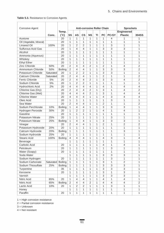
61
5. Chains and Environments
Table 5.3. Resistance to Corrosive Agents
Corrosive Agent Anti-corrosive Roller Chain SprocketsTemp. Engineered
Conc. (˚C) SS AS CS NS TI PC PC•SY Plastic 304SS Acetone 20 1 1 1 1 1 1 4 1 1Oil (Vegetable, Mineral) 20 1 1 1 1 1 1 1 1 1Linseed Oil 100% 20 1 2 2 1 1 1 3 1 1Sulfurous Acid Gas 20 1 4 4 1 1 3 3 3 1Alcohol 20 1 1 1 1 1 1 1 1 1Ammonia (Aqueous) 20 1 1 1 1 1 1 1 1 1Whiskey 20 1 1 1 1 1 1 1 1 1Ethyl Ether 20 1 1 1 1 1 1 1 1 1Zinc Chloride 50% 20 2 4 4 2 1 2 1 4 2Ammonium Chloride 50% Boiling 2 4 4 1 1 3 3 3 2Potassium Chloride Saturated 20 1 2 2 1 1 3 3 1 1Calcium Chloride Saturated 20 2 4 4 1 1 2 1 1 2Ferric Chloride 5% 20 2 4 4 2 1 3 3 4 2Sodium Chloride 5% 20 1 2 2 1 1 1 1 1 1Hydrochloric Acid 2% 20 4 4 4 4 1 4 1 4 4Chlorine Gas (Dry) 20 2 4 4 2 1 3 1 4 2Chlorine Gas (Wet) 20 4 4 4 2 1 3 1 4 4Chlorine Water 20 4 4 4 1 1 4 3 4 4Oleic Acid 20 1 1 1 1 1 1 3 1 1Sea Water 20 2 4 4 1 1 2 1 1 2Sodium Perchlorate 10% Boiling 1 4 4 1 1 3 3 3 1Hydrogen Peroxide 30% 20 1 2 2 1 1 4 1 4 1Gasoline 20 1 1 1 1 1 1 1 1 1Potassium Nitrate 25% 20 1 1 1 1 1 1 3 1 1Potassium Nitrate 25% Boiling 1 4 4 1 1 3 3 3 1Vinegar 20 2 4 4 1 1 2 1 2 2Potassium Hydroxide 20% 20 1 1 1 1 1 1 1 1 1Calcium Hydroxide 20% Boiling 1 1 1 1 1 1 1 3 1Sodium Hydroxide 25% 20 1 1 1 1 1 1 1 1 1Stearic Acid 100% Boiling 4 4 4 1 1 4 3 1 4Beverage 1 1 1 1 1 1 1 1 1Carbolic Acid 20 1 1 1 1 1 4 1 4 1Petroleum 20 1 1 1 1 1 1 3 1 1Water (Soapy) 20 1 1 1 1 1 1 1 1 1Soda Water 1 1 1 1 1 3 3 3 1Sodium Hydrogen 20 1 1 1 1 1 1 3 1 1Sodium Carbonate Saturated Boiling 1 1 1 1 1 3 1 2 1Sodium Thiosulfate 25% Boiling 1 1 1 1 1 3 3 3 1Turpentine 35 1 1 1 1 1 3 3 3 1Kerosene 20 1 1 1 1 1 3 1 3 1Varnish 1 1 1 1 1 3 3 3 1Nitric Acid 65% 20 1 4 4 1 1 4 1 4 1Nitric Acid 65% Boiling 2 4 4 2 1 4 4 4 2Lactic Acid 10% 20 1 2 2 1 1 1 3 1 1Honey 1 1 1 1 1 1 1 1 1Paraffin 20 1 1 1 1 1 1 1 1 1
1 = High corrosion resistance2 = Partial corrosion resistance3 = Unknown4 = Not resistant

62
Basics
Bearing roller chain and bearing bush chain contain rotating elements, sothey are very sensitive to particulate contamination. Make sure you installfixed seals when operating either of these.

63
6. BASIC LAYOUTSTo achieve the maximum benefit from a chain drive, it is important to
arrange chains and sprockets properly. In the following section, we willexplain some examples.
6.1 BASIC LAYOUTS OF WRAPPING TRANSMISSION CHAINS
6.1.1 General ArrangementsWhen designing the wrapping transmission drive, the center line of both
sprockets should be close to horizontal. The angle of inclination may be up to60˚. The slack should be on the lower side.
The center distance of the sprockets should be 30 to 50 times the pitch ofthe chain. When the chain is subjected to fluctuating load, the center distanceof the sprockets should be less than 20 times the chain pitch. This is shown in Figure 6.1.
Figure 6.1 Drive Positions
Slack
Sla
ck
Sla
ck
Up to 60°Up to 60°

Figure 6.2 Short Center Distance
6.1.2 Special Layouts1. Slack side on top (Figures 6.2 and 6.3)
If the shaft center distance is short, proper chain tension should be maintained by adjusting the shaft center distance.
If the shaft center distance is long, do not allow the two sides of the chain to touch each other. Reduce slack span by installing an idler.
2.High chain speed and fluctuating loadsIn this case, the chain’s characteristic frequency, impact period of the driven
shaft, or polygonal action created by the chain/sprocket engagement, may cre-ate large chain vibrations. A guide shoe made of NBR rubber or UHMW poly-ethylene will help reduce vibrations.3. Vertical or near-vertical shaft centers
Install an automatic tensioner to eliminate excess chain slack. This is impera-tive if the driving shaft is on the bottom (Figure 6.4).
64
Basics
Figure 6.3 Long Center Distance
Figure 6.4 Vertical Drive
Idler
Idler
Idler
Take-up

6.1.3 Special ArrangementsChains may be arranged as shown in Figure 6.5 to transmit power. Check the
manufacturer’s specific suggestions on special layouts.
6.2 BASIC CONVEYOR CHAIN LAYOUTS
6.2.1 Horizontal Conveyor Arrangement1. Guide rail arrangement
Chain slack may be eliminated by supporting the entire return side with a guide rail and installing a take-up on the driven shaft. The typical arrange-ment is shown in Figure 6.6 (1). This arrangement can be adapted for reversing drives.
65
6. Basic Layouts
(1) Roller Drive
Figure 6.5 Some Special Arrangements
(3) Multiple Drive
(2) Vertical Shaft Drive
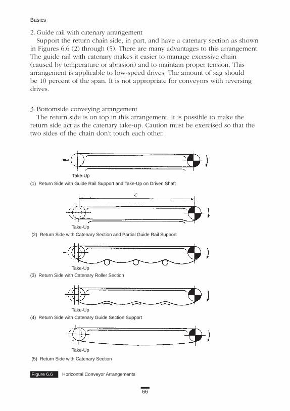
66
Basics
2. Guide rail with catenary arrangementSupport the return chain side, in part, and have a catenary section as shown
in Figures 6.6 (2) through (5). There are many advantages to this arrangement.The guide rail with catenary makes it easier to manage excessive chain(caused by temperature or abrasion) and to maintain proper tension. Thisarrangement is applicable to low-speed drives. The amount of sag should be 10 percent of the span. It is not appropriate for conveyors with reversingdrives.
3. Bottomside conveying arrangementThe return side is on top in this arrangement. It is possible to make the
return side act as the catenary take-up. Caution must be exercised so that thetwo sides of the chain don’t touch each other.
Figure 6.6 Horizontal Conveyor Arrangements
(1) Return Side with Guide Rail Support and Take-Up on Driven Shaft
(2) Return Side with Catenary Section and Partial Guide Rail Support
(3) Return Side with Catenary Roller Section
(4) Return Side with Catenary Guide Section Support
(5) Return Side with Catenary Section
Take-Up
Take-Up
Take-Up
Take-Up
Take-Up

67
6. Basic Layouts
6.2.2 Vertical Conveyor ArrangementInstall a brake or anti-reverse clutch on the driver in case the machine stops
while conveying objects. This is shown in Figure 6.7. The chain may vibrate considerably due to the characteristic frequency of the
chain, impact period of the driven shaft, or the polygonal action of the chainand sprocket. Therefore, install a guide shoe to prevent vibration.
6.2.3 Inclined Conveyor ArrangementAn inclined conveyor is set up the same way as a horizontal conveyor.
6.2.4 Horizontal Circulating Conveyor Arrangement If the shafts are vertical (Figure 6.8), install a guide roller or guide shoe to
the chain to keep the chain from hanging down. This method is covered inmore detail in the Applications Section of this book.
NOTE: For all conveyors, the use of a take-up is suggested. Take care notto overtension the chain, or the result will be increased wear between thepin and bushing. Also, if there is a corner roller guide, bushing/rollerwear will occur. There must be adequate take-up allowance.
6.3 SUPPORTING THE ROLLER OF A CONVEYOR CHAINSupport both the conveying side and the return side of the chain vertically
and restrain them horizontally. Figure 6.9 shows examples of supporting eachtype of roller and attachment.
Figure 6.7 Vertical Conveyor Arrangement Figure 6.8 Horizontal Circulating Arrangement
Take-Up Take-Up

68
Basics
Figure 6.9 Supporting the Roller of a Conveyor Chain
R-Roller (S-Roller) F-Roller Outboard Roller Chain
Ret
urni
ngC
hain
Sid
eC
onve
ying
Cha
inS
ide
Pusher

69
Figure 7.1 Installing a Chain Figure 7.2 Direction in which the Clip is Installed
7. MANIPULATION OF CHAINSYou’ve made your selection, ordered the chain, and it arrives. Now what? In
this chapter, we will review how to get started. Specifically, we will discussinstalling chain on the equipment; checking the accuracy of the installation;and testing, inspecting, and lubricating for start-up.
The guidelines in this chapter will get you started, but refer to your specificmanufacturer’s catalog for details.
7.1 TRANSMISSION CHAINS, SMALL PITCH CONVEYOR CHAINS
7.1.1 InstallationMost transmission chains are sold in standard lengths, usually 3,048 mm
(10 ft). The length may vary, depending on the size of the chain. Small pitchconveyor chains may be special ordered in lengths of chain as required.
The first thing you must do is cut the chain to the length you need.
Tools: Angle grinder (to cut the riveted parts), chain vise, punch, hammer,chain screw.
MethodStep 1. Grind the riveted portion of the two pins with the angle grinder.
If the chain has cottered pins, remove them.Step 2. Secure the chain in the chain vise. Using the primary punch and the
secondary punch (or the chain screw), remove one set of pins.Step 3. Install both ends of the chain onto sprockets and join with
connecting links (Figure 7.1). Be sure to install the clips or cotter pins as shown in Figures 7.2 and 7.3.
Direction of Travel

70
Basics
7.1.2 Installation AccuracyAfter installing the chain, you need to check the accuracy of the installation.
This involves verifying the amount of slack and the precise positioning of theshafts.
7.1.2.1 Chain SlackThe chain slack that you can move by hand (length SS', see Figure 7.4)
should be about 4 percent of the span (length A-B) unless one or more of thefollowing conditions apply:
• The center line of sprockets is vertical or almost vertical.• The center distance of sprockets is more than 1 m.• The chain is subjected to heavy loads and frequent starts.• The chain is subjected to suddenly reversing loads.If one or more of these conditions apply to your operation, make the chain
slack (length SS') about 2 percent.
Figure 7.3 Angle of Legs for Cotter Pins
Figure 7.4 Chain Slack
Cotter Pin T-pin Z-pin
Span

Figure 7.5 Horizontal Positioning of the Shafts
Figure 7.6 Parallelism of the Shafts
Figure 7.7 Alignment of Sprockets
Distance between Shafts GapUp to 1 m ± 1 mm
± Distance between Shafts (mm)1 m to 10 m1,000
Over 10 m ± 10 mm
Level
Straight Edge
Gap
71
7. Manipulation of Chains
7.1.2.2 Horizontal Precision and Parallelism of the ShaftsPosition of the shafts is shown in Figure 7.5, Figure 7.6, and Figure 7.7. 1. Check the horizontal specification with a level. The shafts should be
horizontal within ±1/300.2. Check the parallelism with a scale. They should be within
(length A – B) / L = ±1/300.3. Align the sprocket faces within tolerances shown in the table (Figure 7.7).

72
Basics
7.1.3 Start-Up
7.1.3.1 Prestart-Up ChecklistBefore you start running the chain, check the following: 1. Connecting plates, clips, and cotter pins are installed correctly.2. The chain slack has been properly adjusted.3. Adequate lubrication is available.4. The chain doesn’t touch any objects, like chain cases, etc.5. There are no objects in the chain area, and all is clean.
7.1.3.2 Start-Up TestBefore beginning full operation, turn on the power and check the following:1. Sound. There should be no strange noises. Make sure the chain doesn’t
touch the case.2. Vibration. Look for excessive chain vibration.3. Sprocket-chain interaction. Make sure the chain doesn’t climb over
the sprockets.4. Sprockets. Be sure the chain separates smoothly from the sprocket.5. Chain articulation. The chain should be articulating smoothly.If you notice any of these conditions, do not begin operation. Equipment or
chain could be damaged. Correct any problems before proceeding. (See Basics Section 7.1.6 for additional information.)
7.1.4 LubricationPower transmission chains and small pitch conveyor chains are usually pre-
lubricated with rust-prevention oil before shipping. Nevertheless, it is essentialto lubricate roller chain. Properly lubricated chain has a longer wear life and isless likely to develop rust.
Lubricate the chain where the tension is minimal, applying the lubricant inthe clearance between the link plates (Figure 7.8).
Figure 7.9 shows the lubrication method and type of oil. Table 7.1 showssuggested lubricants for low-speed operation. If your operation runs at highspeeds or in very high or low temperatures, refer to the manufacturer’s catalogfor information on proper lubrication.
Figure 7.8 Lubricate Chain in the Clearance Between Link Plates

73
7. Manipulation of Chains
Figure 7.9 Proper Lubrication Methods
Method Quantity of Oil
Manual Application. Oil should be applied at fixedOil is applied with an oil intervals, usually about every eightfiller or brush on the slack hours, or as often as necessary to side of the chain. prevent the bearing areas from
becoming dry.
Drip Lubrication. Apply 5 to 20 drops of oil per minuteA simple case can be used. for every strand of chain. ActualOil from the oil cup is quantity depends on the speed.supplied by drip feeding.
Oil Bath Lubrication. Chain should be submerged in oilThe chain is installed in a 6 mm to 12 mm. If h is too large,leak-free casing. the composition of the oil may
change due to heat generated and lose some of its effectiveness.
Table 7.1 Suggested Lubricants
Ambient Temperature RangeChain No. -10°C ~ 0°C 0°C ~ 40°C 40°C ~ 50°C 50°C ~ 60°CRS50 and smaller SAE10W SAE20 SAE30 SAE40RS60 • RS80 SAE20 SAE30 SAE40 SAE50RS100 SAE20 SAE30 SAE40 SAE50RS120 and larger SAE30 SAE40 SAE50 SAE50
7.1.5 InspectionChains are reliable components of a transmission machine. If you selected
the proper chain and use it within its specified conditions, the chain will lastfor a long time.
However, you must perform regular inspections on the chain to make sure itis in good condition and operating correctly. Perform inspections monthly or

74
Basics
more often if the chain is used in harsh environments. Why are inspectionsimportant? Over the life of a chain, the pins and bushings wear gradually.There may have been an unexpected shock load on the line, or a malfunction-ing oven might expose the chain to very hot conditions.
During an inspection, make sure to check for the following conditions:• Cracks in the link plates (Figure 7.10). • Cracks in the rollers (Figure 7.11). • Rotated pins (Figure 7.12).• Wear on the end surfaces of link plates (Figure 7.13).If you find any of these conditions, take immediate steps to correct the
problem. A quick checklist is included in Table 7.2. In addition, some trou-bleshooting tips are included in Section 7.1.6.
Table 7.2 Inspection Checklist
Procedure Inspection
1. Visually check In addition to the items to check during operation given in Section 7.1.3, alsothe chain during confirm that the lubrication conditions are suitable. (Look at both the method and operation. amount of lubrication.)
2. Stop the chain 1. Check the external cleanliness, corrosive, and lubrication conditions; also look and carefully for scratches or other damage to the link plate side and edge surfaces, pin edges, inspect each part and roller surfaces.of the chain and 2. Inspect for pin rotation and the gap between the plate and the pins.sprocket. 3. Inspect the sprocket teeth surfaces and teeth side surfaces for scratches or marks.
4. Measure the elongation of the chain due to wear.5. Check the flex of the chain and the spin of the rollers.6. When using a terminating device for lift applications, inspect the wear of the terminator and the wear of the pins. Also, check for proper installation.
Figure 7.10 Example of a Crack on a Link Plate Figure 7.11 Cracks on the Rollers
Figure 7.13 Wear on the End Surfaces of the PlatesFigure 7.12 Rotation of the Pins
Correct Position Rotated Position
Positions Where Cracks are Likely to Develop
5% of H
H
7.1.6 Troubleshooting and Problem-SolvingIf you find something wrong with a chain during start-up or regular inspec-
tion, it may require treatment or you may need to replace it with a new chain.A variety of problems and their solutions is shown in Figure 7.14.

SymptomChain is riding up on the sprocket.
Unusual noises.
Excessive vibrations in chain.
The chain winds onto the sprocket (poor separation from thesprocket teeth).
Rusting of the chain.
Excessive wear at the inside surface of link platesand sides of sprocket teeth.
Excessive wear at the link plate side surfaces and pinheads.
Possible CausesThe chain and sprocket do notmatch.
Excessive load.
Elongation of the chain due to chain wear or excessively wornsprocket teeth.
Improper installation of the sprocket or axle.
Chain casing or bearings are loose.
Excessive or insufficient slack in the chain.
Excessively worn chain or sprocket.
Not enough lubrication.
Chain is resonating with a periodic external force.
Load fluctuations are excessively large.
Span between axles is too large.
Excessive slack in chain.
Elongation of the chain due tochain wear or excessively worn sprocket teeth.
Improper lubrication or poorenvironment.
Improper installation.
Improper installation of guides, etc.
RemedyReplace the chain or sprocket with the correct size.
Decrease the load, or increase the number of strands or size of the chain.
Replace with new chain and sprockets.
Inspect and correct.
Tighten all bolts and nuts.
Adjust the distance between axles to obtain the properamount of slack.
Replace the chain and sprocket with new chain and sprocket.
Provide proper lubrication according to the operating conditions.
Change the chain’s mode of vibration.1. Preventing resonance.
a. To change the natural frequency of the chain.• Alter the effective tension either by applying an
initial tension or adjusting the existing one.• Install a tensioner to change the chain span.• Replace the chain. Choose a different quality and
spring coefficient.b. Change the vibration frequency.
• Change the speed of rotation ofthe sprocket.
• Re-evaluate the device set-up.2. Mechanically reducing the vibrations.
• Install a guide shoe.• Install a self-adjusting
tensioner on the slack side.
Reduce fluctuations with fluid coupling or similar technique.
Install an idler.
Adjust the chain length or distance between axles. Install a tensioner.
Replace with new chain and sprocket.
Replace chain and protect it from the environment withchain casing or proper lubrication.
Correct sprocket and axle installation.
Check the condition of the guides, and increase the gap between the guides and chain.
75
7. Manipulation of Chains
Figure 7.14 (i) Troubleshooting Chain Symptoms and RemediesTransmission Chain, Small Conveyor Chain
Chain Guide
Chain Tensioner

Symptom
Improper flex or bending of chain, tight joints.
Spreading of linkplates.
Symptom
Breakage of link plate.
Possible Causes
Chain is not installed correctly.
Contamination from metaldust or dirt because ofimproper lubrication.
Excessive load or bent pin.
Corrosion or rusting.
Seizing from improper lubrication.
Seizing of pin and bushing. Pin and bushingseized from high-speedoperation. This causesimproper bending and can lead to chain breakage.
Uneven or excessive loading caused by improper installation.
Possible Causes
Excessively large shock load.
Vibrations in the chain.
Large inertia in the drivenmachine (excessive load).
Corrosion.
Remedy
Inspect the installation and correct as necessary.
Remove the chain, wash it thoroughly, and provide proper lubrication.
Reduce the load or increase the number of or sizeof chains. Replace chain with a larger size.
Install a chain casing to protect the chain.
Provide proper lubrication according to the operating conditions.
Provide the proper operating conditions.
Replace with new chain and correct installation.
Remedy
Reduce shock loads by making the start-up, stopping,and other actions smoother (installing a shockabsorber, etc.). Increase the size or number of chains.
Install an anti-vibration device (for example, tensioner or idler). Refer to “Excessive vibration in chain.”
Increase the size or number of chains.
Replace with a new chain. Install a casing to protect the chain. Otherwise, periodically clean the chain.
Figure 7.14 (ii) Link Plate
76
Basics
Figure 7.14 (i) Transmission Chain, Small Conveyor Chain (Cont.)

Symptom
(1) Static fracture.Stretching the link platewith a tensile loadbeyond its breakingload will cause it tostretch and then break.
Cracks in the linkplates (fatigue), whichare perpendicular tothe direction of pull.
Deformation in the linkplate holes.
Corrosion stresscracks appear, usuallyas bow-shaped cracksin the link plate.
Symptom
Breakage of pin.
(1) Static fracture.The type of fracturefound when subjectingthe chain to the break-age test. Occurs whenchain is subjected to aload greater than itsbreakage strength.
Possible Causes
(2) Fatigue fracture.By repeatedly applying aload past its fatigue limit(fatigue strength), thefatigue will start at holesand then suddenly break.
Loads are greater thanallowable.
Excessive load.
The chain is being usedin an acidic or alkaline environment. (This is notcaused by a repetitiveload.)
Possible Causes
Excessively large shock load.
Subject to a repetitive loadgreater than the fatiguelimit of the pin.
Corrosion.
(2) Fatigue fracture.Occurs when the pin isrepetitively subjected toloads greater than itsfatigue limit. Recheck thesize of the peak load andformulate a countermea-sure.
Remedy
(3) Offset plate fatigue.Offset plates are bent at the center, and the result-ing concentration of stress at the bend can cause afatigue break. Avoid using offset links in high-stressapplications.
Remove all large or excessively repeating loads.Otherwise, increase the size or number of chains.Replace with a new chain.
Remove the cause of the excessive load.Replace with a new chain.
Install a casing to protect the chain from the environment. Consider a chain with a high resistance to corrosion stress cracks.Replace with a new chain.
Remedy
Reduce shock loads by making the start-up, stopping, and other actions smoother.
Remove the large repetitive load. Otherwise,increase the size or number of chains.
Install a casing to protect the chain. Periodicallyclean and lubricate the chains.
(3) Shock-induced bending fracture.The pin is subjected to a large shock load. A pin is especially susceptible to this when the surface is corroded.
Figure 7.14 (ii) Link Plate (Cont.)
77
7. Manipulation of Chains
Figure 7.14 (iii) Pin

78
Basics
Symptom
Pin rotates or beginsto stick out.
Wear or rust occursonly at the connectingpin in a tension application or similaroperation.
Symptom
Roller and/or bushingsplits and falls off.
Fatigue fracture.
Roller does not rotate.
Roller is opening up.
Roller is becominghourglass shaped.
Possible Causes
Excessive load or improper lubrication.
Operating a chain at highload without proper lubrication can create fric-tion between the pin and bushing, causing the pin torotate. In this condition,the pin may come out,leading to chain breakage.
Improper initial lubricationat installation.
Possible Causes
Excessive load or speedof rotation.
Inadequate lubrication.
RS11SS, RS15, RS25,RS35.
The inner plate is movinginward, or the bushing iscracked.
Foreign particles have got-ten between the bushingand roller.
Excessive load.
Excessive load or inade-quate lubrication.
Remedy
Replace with new chain. Improve the lubrication or loading conditions.
Replace with new chain immediately. Do not weld orreuse the pins. (Dispose of the old chain to be surethat it is not used by mistake.) Also, if the pin head or link plate surface is worn, check the installation.
Replace the connecting link. If pin wear is exces-sive, replace the chain also. Take special care toproperly install the connecting section for devicessuch as terminators used for tension applications.
Remedy
Choose a different chain according to the transmission capacity table.
Replace the chain. Provide adequate lubricationaccording to the operating conditions.
A bushed chain and not a roller chain is being used.
Replace with a new chain. Re-inspect the installation and load conditions.
Periodically clean the chain. Install a casing to protect the chain.
Reduce the load. Provide adequate lubrication.
Replace with new chain. Improve the lubrication orloading conditions.
Reached the point of fatigue during operation and eventually broke. Impact by thesprocket teeth at a force exceeding the chain’s transmission capacity.
Normal
Figure 7.14 (iii) Pin (Cont.)
Figure 7.14 (iv) Bushing / Roller Problems

79
7. Manipulation of Chains
Figure 7.15 Installation of a Large Pitch Conveyor Chain
7.2 LARGE PITCH CONVEYOR CHAINS
7.2.1 Installation Large pitch conveyor chain is usually supplied in the length specified.
Therefore, you don’t need to cut these chains. Disconnect the outer plate onthe end of each chain set and use this as a connecting link.
Tools: hammer, setting tool, monkey wrench, or T-pin bender
Method (Figure 7.15)Step 1. At the outer link on the end of the chain, the outer plate on the T-pin
side is pushed in lightly. Remove the outer plate with the hammer.
Step 2. Using this outer link, connect the inner links of both ends of the chain.
Step 3. Tap the outer link plate onto the link with the hammer until the pin is completely inserted into the link plate.
Step 4. When you see the T-pin hole, insert the new T-pin into it. Using the monkey wrench or T-pin bender, bend the T-pin more than 30˚ to lock it into place.
Outside Link
Inside Link
Alternately hit the pinheads while supportingother side of plate.
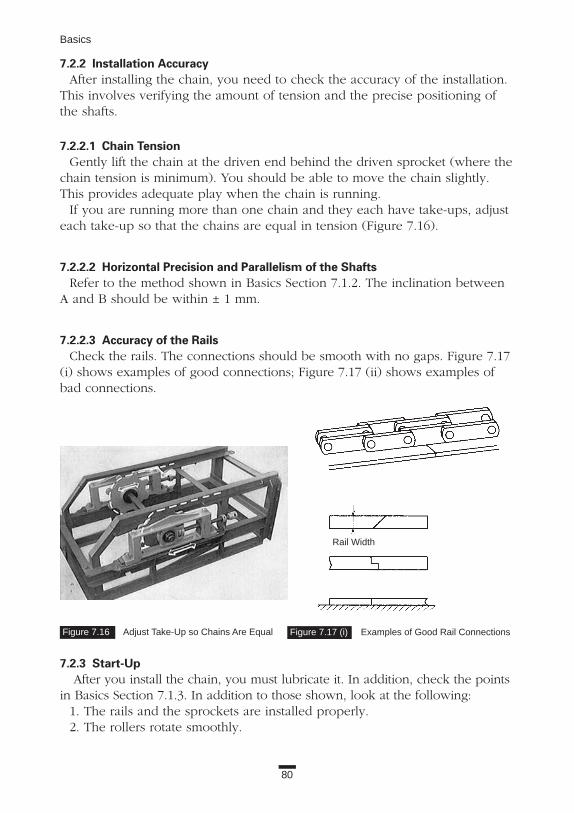
7.2.2 Installation AccuracyAfter installing the chain, you need to check the accuracy of the installation.
This involves verifying the amount of tension and the precise positioning ofthe shafts.
7.2.2.1 Chain TensionGently lift the chain at the driven end behind the driven sprocket (where the
chain tension is minimum). You should be able to move the chain slightly.This provides adequate play when the chain is running.
If you are running more than one chain and they each have take-ups, adjusteach take-up so that the chains are equal in tension (Figure 7.16).
7.2.2.2 Horizontal Precision and Parallelism of the Shafts Refer to the method shown in Basics Section 7.1.2. The inclination between
A and B should be within ± 1 mm.
7.2.2.3 Accuracy of the RailsCheck the rails. The connections should be smooth with no gaps. Figure 7.17
(i) shows examples of good connections; Figure 7.17 (ii) shows examples ofbad connections.
7.2.3 Start-UpAfter you install the chain, you must lubricate it. In addition, check the points
in Basics Section 7.1.3. In addition to those shown, look at the following:1. The rails and the sprockets are installed properly. 2. The rollers rotate smoothly.
80
Basics
Figure 7.16 Adjust Take-Up so Chains Are Equal Figure 7.17 (i) Examples of Good Rail Connections
Rail Width

81
7. Manipulation of Chains
7.2.4 Lubrication Proper lubrication is very important for chain operation. The manufacturer
usually ships large pitch conveyor chain without lubrication or rust protection.Therefore, before start-up, you must apply lubricating oil, such as SAE30 orSAE40, by brush or drip. You should lubricate mainly the bushings and rollers(Figure 7.18).
To maximize the life of your chain during normal operation, lubricate it atleast once a week.
NOTE: Lubricate more often immediately after you install the chainand if the chain is used in harsh conditions (for example, at highspeed, high load, high temperature).
7.2.5 InspectionA chain is a very reliable part of a conveying machine. You can expect very
long life from a chain if you’ve followed the selection and operating guidelinesproperly.
However, it is important to inspect a chain periodically to make sure it is operating correctly. During long-term use, pins, bushings, and rollers graduallywear. An unexpected shock load or the operating environment may cause prob-lems. To avoid any accidents caused by these factors, you must regularly inspectthe items shown in Figure 7.19, and address any problems as described inBasics Section 7.2.6. Plan at least monthly inspections. If the chain is used inharsh conditions, inspect it more frequently.
7.2.6 Troubleshooting and Problem-SolvingIf you find something wrong with a chain during start-up or regular inspec-
tion, it may require treatment as shown in Figure 7.19, or you may need tochange to a different type of chain.
Figure 7.17 (ii) Examples of Poor Rail Connections
Figure 7.18 Proper Lubrication of Large Pitch Conveyor Chains
Chain entrance guide must have sloped and radiused ends.

82
Basics
Symptom
Excessive wear at the inside of the chain’s link plates or the teethsurfaces.
Improper flex or bending of the chain.
The chain is winding on the sprocket.
The chain is climbing up on the sprocket.
Unusual noises.
Rusting of the chain.
Improper roller spin and uneven roller wear.
Possible Causes
Improper centering of the sprocket.
The chain is being pushed to the side.
Vibration caused by the inaccurate finishingof the sprocket’s axle hole.
Rusting or corrosion.
Particles of the conveyed material have contaminated the pin, roller, and bushings.Otherwise, contamination from foreign particles.
Deformation of the chain caused by improper installation.
Inadequate lubrication.
Operation in extremely high temperatures (over 400°C).
Seizure from excessive loads.
Pin bending due to excessively high loading.
Too much slack in the chain.
Excessively worn sprocket. The chain and sprocket do not match.
The chain and sprocket do not match.
The total arc of contact with the chain on the sprocket is insufficient.
Excessive load.
Inadequate back-tension.
Excessive elongation of the chain due to wear.
The distance between the center of the chain and the sprocket do not match.
Inadequate lubrication to the contacting portions of the pin and bushing.
Inadequate lubrication to the contacting portions of the bushing and roller.
Winding or rising on the sprocket.
Loose chain casing or axle bearing.
Interference of the casing with the chain or other moving part.
Excessive wear in the chain or sprocket.
Improper setting of the guide rail.
Inappropriate selection of material.
Condensation.
Excessive load on roller.
Particles of the conveyed material, or otherforeign particles, have gotten between bushing and roller.
Particles of the conveyed material, or other foreign particles, have built up onto the rail.
The lubricant is falling on the roller surface and rail without entering between the bushingand roller, and between the roller and link plate.
The bushing and roller have rusted together.
The inner plate is moving sideward.
The bushing is cracked.
The side surface of the roller is contacting the side of the link plate due to a thrust load.
The chain and sprocket do not match. Excessively worn teeth.
Remedy
Remove the chain and correct the centering of the drive and driven sprockets.
Remove the cause of the push and/or install a guide roller.
Check and correct the faulty locations and replace the sprocket with a new part.
Install a partition to protect the chain. Select a chain of suitable specification (for example, MT type).
Install a partition to protect the chain. Select a chain with large clearance between the pin, bushing, and roller.
Inspect and correct the installation of the sprockets and axles.
Inspect the lubrication or look into wear-resistant chain (for example, CT or BT specification).
Provide adequate clearance.
Provide periodic lubrication. Reduce load.
Reduce load.
Adjust the chain length or distance between axles, or install a tensioner.
Replace the chain and/or sprocket with the correct-sized part.
Replace the chain or sprocket with the correct-sized part.
Have the total arc of contact be at least three teeth on the sprocket.
Reduce the load (for example, by installing a shock absorber).
Adjust the catenary or take-up idler, or install a tensioner.
Replace with a new chain.
Inspect and correct.
Provide sufficient lubrication.
Provide sufficient lubrication. Use a bearing roller or plastic roller.
See previous symptom.
Tighten all nuts and bolts.
Inspect and correct.
Replace the chain or sprocket. (Replace all chains connected.)
Inspect and correct.
Select a more suitable chain material. Protect the chain from the environment. Apply a rust inhibitor.
Eliminate the temperature difference between inside and outside of conveyor (using insulation, etc.).
Provide sufficient lubrication. Consider bearing roller or GT chain specification.
Periodic cleaning. Install partition to protect chain.
Periodic cleaning. Install partition to protect chain.
Select the appropriate lubricant and lubrication method.
Select the appropriate specifications (RT, etc.).
Replace with a new chain. Re-inspect the installation and load conditions.
Reduce the load and lower the speed of rotation.
Eliminate the cause of the thrust load.
Check for tooth deformation.
Rail Step
Rail InclineReturn Radius
Figure 7.19 (i) Troubleshooting Large Pitch Conveyor Chain

Symptom
The roller is opening up.
The roller or bushing is split (falling off).
The roller is becoming hour-glass shaped.
The chain sticks and slips.(This can be caused by acombination of many prob-lems. Therefore, the listedremedies may not solve theproblem.)
Excessive wear of the sprocket teeth valleys anddrive sides.
Excessive wear of the insidelink and pin on one side of anNF block chain or BF chain(no roller).
Sudden fracture of the linkplate.
Crack in the link plate.(1) Fatigue breakage.
Possible Causes
Excessive load.
Excessive load.
The number of teeth is too few with respectto the conveyor speed.
Excessive load or inadequate lubrication.
Excessively worn rail.
Change the rolling friction coefficient of thechain.
The conveyor speed is too slow.
Insufficient rigidity in the frame.The conveyor chain is small compared tothe device.
The force of friction is excessively large.
The machine is too long.
Inconsistent speeds due to movementalong a polygon-shaped path.
Excessively worn chain.
Insufficient number of teeth.
A BF chain (no rollers) is being used.
The hardness of the teeth is insufficientwith respect to the load and conveyedmaterial or foreign particles.
The chain and sprocket do not match.
Increased internal tension when meshingwith the sprocket.
Excessive load.
Weakening of chain caused by excessivewear or corrosion.
The link plates are pressed outward by thesprocket.
Excessive load or excessively large repetitive load.
The factor of safety is not sufficient.
Repetitive load on attachment.
Remedy
Reduce the load, provide adequate lubrication, remove any large steps in the rail.
Reduce the load. Provide adequate lubrication.
Increase the number of teeth. Decrease the speed.
Increase the lubrication, improve loading conditions, andreplace the chain with a new one.
Correct or replace the rail.
Lubricate the chain and clean the rail.Lubricate with Tsubaki oil.Change to a bearing roller chain.
Increase the speed.
Increase the frame rigidity; increase the chain modelnumber.Decrease the slack in the drive roller chain.
Lubricate the chain. Change to a bearing roller chain.
Divide the conveyor system into sections to decreasethe length.
Use a 12- or-more-toothed drive sprocket.
Replace both the chain and sprocket.
Increase the number of teeth.
Change to an RF chain (with rollers).
Use a sprocket with hardened teeth or changeableteeth.
Replace the chain or sprocket with one that is of the correct size.
Attach the supporting block to the sprocket. Reduce theload. Lubricate the chain and sprocket.
Eliminate causes of the overloading. Install a safetydevice (for example, Shock Relay). Increase chain size.
Replace with new part.Install a cover to protect the chain.Periodically lubricate chain.Select a chain with the proper specifications for the application.
Check and correct the installation.Excessively worn chain or sprocket.Check if the chain and sprocket match, and correct as necessary.
Eliminate overloading or large repetitive loads.
Increase the size or specifications of the chain toincrease the factor of safety.Replace with a new chain.
Eliminate overloading or large repetitive loads; increasethe chain size to increase the allowable load of theattachment.
83
7. Manipulation of Chains
Figure 7.19 (ii) Troubleshooting Large Pitch Conveyor Chain

84
Basics
Symptom
(2) Corrosion stress crack. (Bow-shaped crack in heat-treated metal plates.)
Deformed link plate holes andpin rotation (the pin is shiftedfrom its normal position).
(1) Pin fatigue fracture.(2) Pin corrosive fatigue.(3) Pin brittle fracture.(4) Pin sudden fracture.
Excessive wear caused bythe conveyed material.The surface is worn away.
Excessive wear from corro-sion. Link plates not madefrom an anti-corrosive materi-al are corroding.
Excessive wear from electro-chemical corrosion. Only thecontact surfaces are worn.
Possible Causes
The chain is being used in an acidic or alkaline environment. (This is not causedby a repetitive load.)
Excessive load.
Improper installation of the connecting link.
Excessive load and inadequate lubrication.
Seizure of the pin and bushing, improperbending or flex of the chain.
The factor of safety used for calculation ofthe peak load versus the breakage loadwas too small. The peak load acted like arepetitive load on the chain.
The pin was subjected to a tensile load at theside of the fracture origin, where the breakthen progressed. Chain is especially suscep-tible to this when the pin surface is corrodedand weak against bending stresses.
Poor environment.
Excessive load.
The chain is contaminated with especiallyabrasive materials, such as mineral pow-ders, etc., being worn away by the chainsurface itself.
The chain is exposed to acidic or alkalinesubstances, and, therefore, more suscepti-ble to machine wear, which then progress-es much faster.
When the chain is covered with water orpasses through a solvent, the portions incontact suffer galvanic corrosion.
Remedy
Install a cover to protect the chain from the environment. Replace with new part. Use a chain with a high resis-tance to corrosion stress cracks.
Eliminate the cause of overloading and replace chainwith a larger size.
Replace connecting link with a new one.
Replace with a new chain and improve the lubricationand loading conditions.
Increase the chain size. Increase the clearance betweenthe pin and bushing.
Recheck the size of the peak load, and eliminate itscause. Replace the chain with a larger size (larger pindiameter).
Recheck the size of the peak load, and eliminate itscause. Replace the chain with a larger size (larger pindiameter).Use a pin made of an anti-corrosive material.
Use an appropriate pin material.
Eliminate the cause of overloading, and replace chainwith a larger size.
Prevent material from falling onto the chain. Use a wear-resistant chain.
Use a material not affected by the chemicals. Use a wear-resistant material for the machine-wornparts.
Use a material not affected by the chemicals. Use awear-resistant material for the machine-worn parts.
Figure 7.19 (iii) Troubleshooting Large Pitch Conveyor Chain
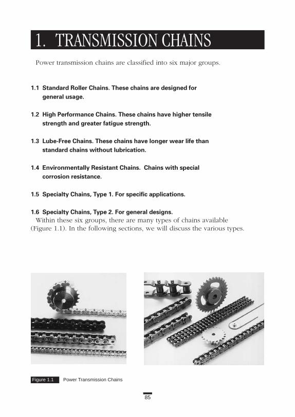
85
1. TRANSMISSION CHAINSPower transmission chains are classified into six major groups.
1.1 Standard Roller Chains. These chains are designed for general usage.
1.2 High Performance Chains. These chains have higher tensilestrength and greater fatigue strength.
1.3 Lube-Free Chains. These chains have longer wear life than standard chains without lubrication.
1.4 Environmentally Resistant Chains. Chains with special corrosion resistance.
1.5 Specialty Chains, Type 1. For specific applications.
1.6 Specialty Chains, Type 2. For general designs.Within these six groups, there are many types of chains available
(Figure 1.1). In the following sections, we will discuss the various types.
Figure 1.1 Power Transmission Chains

86
Applications
1.1 STANDARD ROLLER CHAINS
1.1.1 ANSI Roller Chains (RS)Transmission: General usage
Application ExamplePower transmission chains are widely used throughout the world in a variety
of applications, including drive, tension, shuttle traction, and transmissionreduction operations. Because of this widespread usage, certain internationalstandards are set to ensure that pitch, width, and other key characteristics ofchains and sprockets are standardized. In the United States, power transmis-sion chains must meet ANSI B29.1, thus earning the name ANSI chains. Inother countries, the chains must meet JIS B1801, ISO 606A, or ISO 1395C.
Construction and Features (1) ANSI Roller Chains have the same shape and construction as the chain
shown in Basics Section 1.1.1. There are 14 sizes of roller chains regulat-ed by ANSI. For easy reference, these are numbered 25, 35, 41, 40, 50, 60, 80, 100, 120, 140, 160, 180, 200, and 240. Some manufacturers include chain numbers 320 and 400 to the list of standardized chains.
(2) Chains with a “5” on the right-hand digit of the chain number are bushing chains. Bushing chains do not have rollers.
(3) Number 41 chain is a narrow variation of number 40. (4) This chain number indicates the chain pitch. Here’s how to decipher the
pitch from the chain number. The numbers to the left of the right-hand digit refer to the chain pitch in eighths of an inch. To calculate the pitch, multiply the number by 3.175 mm. For example: 140 = 14 3 3.175 = 44.45 mm pitch, or 14/8 = 1.75 inches.
(5) Each manufacturer adds its own identification stamp prior to the chain number. For Tsubaki, “RS” is the identifier (for example, RS80, RS100). The use of “RS” as an identifier has spread widely; it has become the standard symbol for power transmission roller chains.
(6) There are smaller chains available. Refer to the “Miniature Chain” Section in this book for information on sizes smaller than number 25.
SprocketsVarious sprockets are produced for each size of RS Roller Chain. Sprockets
are identified by the type of base material used in manufacture and by thebore. Here are some basic types:

87
1. Transmission Chains
(1) Carbon steel sprockets with plain bores. (Sintered metal or cast iron are sometimes used.)
(2) Carbon steel sprockets with finished bores, keyway, and setscrews. TAPER-LOCK® and QD® bores are also available.
(3) 304 stainless steel sprockets with plain bores.(4) Engineered plastic sprockets with plain bores.(5) POWER-LOCK® sprockets, which do not require a keyway or setscrew.
Selection and HandlingSee Chapters 4 through 7 in the Basics Section.
1.1.2 BS/DIN Roller ChainTransmission: General usage
Application ExampleBS/DIN power transmission chains are regulated by international standards
(ISO 606B) and are used primarily in Europe. In Japan and the United States,BS/DIN chains are used in transmission equipment imported from Europeancountries or for licensed production.
Selection and HandlingCompared to the same-sized ANSI Roller Chains, the power ratings of
BS/DIN chains in drive applications (tent curve) are a little lower (Table 1.1).
Table 1.1 Power Ratings for Standard ANSI and BS/DIN Roller Chains
Pitch Number of RPM PowerChain No. (mm) Sprocket Teeth (rev./min.) Rating (kW)RS80 25.4 19 500 24.1RS16B 25.4 19 500 22.0RS160 50.8 19 500 76.1RS32B 50.8 19 500 70.0
TAPER-LOCK ® is a registered trademark of Reliance Electric Company. QD® is a registered trademark of and is used underlicense from Emerson Electric Company.

88
Applications
1.2 HIGH PERFORMANCE CHAINSThese are enhanced types of ANSI Roller Chain (RS) in average tensile
strength and/or fatigue resistance. Each chain has different features. Figure 1.2shows the general relationship of high performance chains to ANSI StandardRoller Chain.
NOTE: The multipliers shown in Figure 1.2 compare high performancechain to RS Roller Chain. The comparisons are between products ofTsubaki. You may find the ratio varies by chain size or manufacturer.Refer to a specific manufacturer’s catalog for details.
Figure 1.2 Increasing Fatigue Strength and Tensile Strength of Roller Chains
ANSI RS ROLLER CHAINS
FATIGUE STRENGTH
x 1.1
x 1.2 x 1.2
x 1.1
x 1.3
tt
x 1.4
x 1.55
x 1.45
AVERAGETENSILE
STRENGTH
RS-HT ROLLER CHAINS
SUPER ROLLER CHAINS
SUPER-H ROLLER CHAINS
ULTRA SUPER ROLLER CHAINS
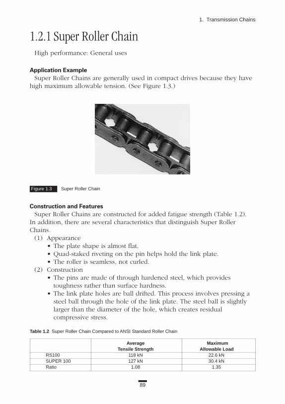
89
1. Transmission Chains
1.2.1 Super Roller ChainHigh performance: General uses
Application ExampleSuper Roller Chains are generally used in compact drives because they have
high maximum allowable tension. (See Figure 1.3.)
Construction and FeaturesSuper Roller Chains are constructed for added fatigue strength (Table 1.2).
In addition, there are several characteristics that distinguish Super RollerChains.
(1) Appearance• The plate shape is almost flat.• Quad-staked riveting on the pin helps hold the link plate.• The roller is seamless, not curled.
(2) Construction • The pins are made of through hardened steel, which provides
toughness rather than surface hardness.• The link plate holes are ball drifted. This process involves pressing a
steel ball through the hole of the link plate. The steel ball is slightly larger than the diameter of the hole, which creates residual compressive stress.
Figure 1.3 Super Roller Chain
Table 1.2 Super Roller Chain Compared to ANSI Standard Roller Chain
Average MaximumTensile Strength Allowable Load
RS100 118 kN 22.6 kNSUPER 100 127 kN 30.4 kNRatio 1.08 1.35

90
Applications
• Connecting link plates are press fit to maintain the higher fatigue resistance.
• The middle link plates of multiple strand chain’s connecting link arenot press fit. They are specially constructed for higher fatigue strength.
• Connecting links are fitted with high-strength spring pins.Because of these features, Super Roller Chains offer higher maximum allow-
able tension, greater tensile strength, and increased shock resistance. Table 1.2shows a comparison between Number 100 Super Roller Chain and StandardRoller Chain. Number 100 Super Roller Chain performs at the same level asRS120. Both have a maximum allowable tension of 30.4 kN.
SprocketsHigh performance chain usually requires carbon steel sprockets. Cast iron
sprockets with few teeth may lack adequate strength. Steel sprockets are avail-able for single or multiple strand. Check the keyway strength of the sprocketsbefore ordering to make sure they provide enough strength.
Selection and HandlingSuper Roller Chains are available in sizes 80 through 240. Smaller
chains (≤60), stainless steel chains, and offset links are not available in SuperRoller Chain.
When installing Super Roller Chain, do not use the connecting link fromStandard Roller Chain. Only special press fit connecting links should be usedwith Super Roller Chains.
Super Roller Chains are susceptible to wear and elongation. Therefore, it isvery important to provide proper lubrication. (Refer to manufacturer’s catalogfor details.)

91
1. Transmission Chains
1.2.2 Super-H Roller ChainHeavy transmission
Application ExampleSuper-H Roller Chains are used in compact and heavy drives. (See Figure 1.4.)
They have greater maximum allowable load, increased tensile strength, andsmaller elastic elongation compared to the same-sized RS Roller Chain.
Construction and FeaturesThe link plates on Super-H Roller Chain are thicker. In fact, the thickness of
the link plate is the same as the next-larger-sized Super Roller Chains. Table 1.3 compares data on number 100 chains.
Figure 1.4 Super-H Roller Chain
Table 1.3 Super-H Roller Chain Compared to ANSI Standard Roller Chain
Average MaximumTensile Strength Allowable Load
RS100 118 kN 22.6 kNSUPER 100-H 145 kN 32.4 kNRatio 1.23 1.43

1.2.3 RS-HT Roller ChainHeavy transmission: Construction machines, agriculture machines, and ten-
sion applications
Application ExampleRS-HT Roller Chains have higher tensile strength and less elastic elongation
in comparison with RS Roller Chains. These characteristics are good for “lift-ing” applications (at low cycles), construction machines, and agriculture equip-ment (Figure 1.5).
Construction and FeaturesCompared with RS Roller Chains, RS-HT Roller Chains have the features
shown below and in Table 1.4.
Appearance(1) Link plate thickness is equal to the next-larger chain.(2) Quad-staked riveting on the pin head helps hold the link plate
on the pin.(3) Rollers are seamless, not curled.
92
Applications
Figure 1.5 RS-HT Roller Chain
Table 1.4 RS-HT Roller Chain Compared to ANSI Standard Roller Chain
Average MaximumTensile Allowable
Strength LoadRS100 118 kN 22.6 kNRS100-HT 142 kN 24.5 kNRatio 1.20 1.08

1.2.4 Ultra Super Chain Super-heavy transmission
Application ExampleUltra Super Chain has the highest tensile strength and greatest allowable ten-
sion of any chain that can mate with a standard sprocket. These features alsoallow the drive train of the equipment to be smaller. (See Figure 1.6.)
Construction and FeaturesUltra Super Chains have the same chain pitch, roller diameter, and width
between inner link plates as ANSI Standard Chain. However, the link platethickness is the same as the next-larger chain. The pin diameter is larger thanANSI Standard Chains. Table 1.5 compares RS100 Roller Chain and 100 UltraSuper Chain. In this chain series, both the average tensile strength and maxi-mum allowable tension are increased, even over Super-H Chains. Number 100Ultra Super Chains have the same maximum tension as RS140, which is twosizes larger.
SprocketsSee “Super Roller Chain” Section.
Selection and Handling(1) Choose these chains using the guidelines for low-speed selection.(2) Ultra Super Chain is available in sizes 100 through 240.
(Number 180 is not available.)
93
1. Transmission Chains
Figure 1.6 Ultra Super Roller Chain
Table 1.5 Comparison of ANSI Standard Chain (RS) with Ultra Super Chain (US)
Average MaximumTensile Allowable
Strength LoadRS100 118 kN 22.6 kNUS100 172 kN 39.2 kNRatio 1.45 1.73

94
Applications
(3) Ultra Super Chain is not available in multiple strand.(4) Due to the hardness of plates being higher than other carbon steel roller
chains, Ultra Super Chains have a greater risk of hydrogen embrittlement.Other points of notice are the same as Super-H Roller Chain.
1.3 LUBE-FREE CHAINS
1.3.1 LAMBDA® Roller ChainTransmission and conveyor: Lube-free type, drive transmission
Application ExampleLAMBDA Roller Chains do not require additional lubrication. This makes
them ideal for “clean” applications like final assembly areas, paper production,and other operations where lubrication could affect the product on line.LAMBDA Roller Chains are available in drive or conveyor styles. (See Figure 1.7.)
Construction and FeaturesLAMBDA Roller Chains are designed for long wear life without additional
lubrication. The bushings are made of oil-impregnated sintered metal, and thepins are specially coated. LAMBDA Roller Chains also have rollers, whichmake them different from other lube-free chains. (The SL series, for example, does not have rollers.)
The features of LAMBDA Roller Chains are as follows:(1) LAMBDA Roller Chains outlast Standard Roller Chains without lubrication
up to 30 times longer at low speed (about 25 m/min.) and seven times longerat medium speed (about 127 m/min.). (See Figure 1.8.)
Figure 1.7 LAMBDA® Lube-Free Chain
Specially coated pin
Oil impregnated sintered bushing
Roller

95
1. Transmission Chains
Figure 1.8 Comparison of LAMBDA® Chains and Other Chains
Lube-F
ree
Cha
in
Oth
erBr
ands
of
Stee
l Rol
ler C
hain
Steel
Rol
ler
Other Brands of Sealed Chain
Lube-Free Chain
Λ (LAMBDA Chain)
Λ (LAMBDA Chain)
Low Wear Elongation LAMBDA® Chain0.5%
0
Wea
rE
long
atio
n
0.5%
0
25m/min.Low
Speed
127m/min.
MediumSpeed
Wea
rE
long
atio
n
Seal
edC
hai n
(2) The rollers on LAMBDA® Roller Chain engage the sprocket more smoothly, reducing power loss.
(3) LAMBDA Roller Chains have the same transmission capacity as equivalently sized ANSI Roller Chains at speeds of 150 m/min. or less.
(4) Because additional lubrication is not required, LAMBDA Roller Chains help prevent contamination of equipment and conveyed objects. This promotes a clean working environment.
(5) LAMBDA Roller Chains are designed to operate in temperatures from -10˚ to 60˚C.
SprocketsSingle strands of LAMBDA Roller Chain run on standard sprockets. Multiple
strand chains require special sprockets that have a wider transverse pitch.
Selection and Handling(1) Drive LAMBDA Roller Chains have thicker roller link plates than RS
Roller Chains. The chains are also wider. Check to make sure that the wider chains will run correctly on your equipment.
(2) When the chain is used in a dusty environment, the dust will absorb the lubrication oil in the bushings, and the bushings may wear in a short time. If conditions are dusty, test the chain in the environment.
(3) If LAMBDA Roller Chain is used in water, the chain will wear faster.(4) When the lubricating oil contained in the bushing is depleted, the chain
should be replaced.
Application Series(1) Nickel-plated LAMBDA Roller Chain is available for higher corrosion
resistance.(2) LAMBDA II lasts twice as long as LAMBDA in temperatures up to 150˚C.

96
Applications
1.3.2 Sealed Roller ChainLube-free type: High-speed transmission, in dusty conditions
Application ExampleSealed Roller Chain may be useful for general industrial applications that run
at high speeds or in dusty conditions. (See Figure 1.9.)
Construction and FeaturesSealed Roller Chains have O-ring seals between the pin link and the roller
link plates. These seals keep the lubricant in and contaminants out. The innerwidth of the chain is the same as ANSI specifications. The total width of thechain is larger than the ANSI measurement because the bushings usuallyextend beyond the roller link plates to protect the O-rings.
Sealed Roller Chains are available in sizes 40 through 100. The average tensile strength is slightly lower than ANSI Roller Chain.
SprocketsStandard sprockets are used for single strand chain.
Figure 1.9 Sealed Roller Chain

97
1. Transmission Chains
Selection and Handling(1) O-ring seals are usually made of acrylonitrile-butadiene rubber, which is
highly resistant to oil, heat, and abrasion. Fluorine rubber O-ring seals are available for high heat operations (greater than 120˚C).
(2) The link plates holding the O-rings are under compression. This means greater force is required to articulate the chain, and the transmittedpower is decreased. At places where the chain tension is low (such as the return side) the strand will retain the bend. The manufacturing tolerances of the O-rings are generally large, therefore, it is difficult to make the bending resistance of O-ring chain smaller and stable.
(3) When the oil film between the O-ring and the link plate is gone, the O-ring will wear and deteriorate. Rubber has a “creeping” property, and it tries to make the contacting surface flat. Therefore, it becomes more difficult to get the lubricant into the working parts.
(4) During long-term operation, the O-rings may start to fall off the chain.Then, the elongation at that spot will progress very rapidly. If this occurs,it is time to replace the chain, even if the total chain has not reached theelongation limit (1.5 percent).
(5) The cost of Sealed Roller Chain is higher than ANSI Standard RollerChain. The higher cost is because of the additional and special parts (O-ring seals, longer pins and bushings). Unfortunately, less expensive stan-dard components cannot be used for Sealed Roller Chain.
Technical TrendChain manufacturers are constantly striving to improve the quality and wear
life of chains in general, including Sealed Roller Chain. In the area of seal research, a variety of shapes of seals has been tested. The
goal is to reduce the bending resistance and yet keep the lubricant in theworking parts. Currently, O-rings are the most practical alternative.

98
Applications
1.4 ENVIRONMENTALLY RESISTANT CHAINSThese are chains that offer high resistance to corrosion or heat due to special
coatings or materials. The approximate relationship between these chains isshown in Figure 1.10.
Table 1.6 shows a variety of environmentally resistant chains and materials.
NOTE: The chains surrounded with a thick line have a temperaturerange of -20˚ to 400˚C. Before using these chains in temperatures out-side this range, contact the manufacturer.
In this Figure, the left-to-right direction shows the relative corrosionresistance (right is more resistant than left). The average tensilestrength or maximum allowable tension may differ even betweenchains of the same size.
Figure 1.10 Environmentally Resistant Chains
ANSI RS ROLLER CHAINS
NP ROLLERCHAINS
PlatingSpecial Nickel Plating
For CorrosiveEnvironments
Special Double Surface Treatment
304SS Stainless Steel
WP® ROLLERCHAINS
SS ROLLERCHAINS
304SS + Engineered Plastic
PC ROLLERCHAINS
Titanium + SpecialEngineered Plastic
High GradeMaterial PC-SY CHAINS
304SS + 630SS
AS ROLLERCHAINS
316SS Stainless Steel
NS ROLLERCHAINS
TITANIUM
TI ROLLERCHAINS
t

Tab
le1.
6C
hain
sfo
rS
peci
alE
nviro
nmen
ts
Co
nd
itio
ns
Ch
emic
als,
Sea
Aci
d,A
lkal
is,
Lo
w/H
igh
No
n-
Ser
ies
Trea
tmen
tS
pec
ialF
eatu
res
and
Ap
plic
atio
ns
Wat
erW
ater
San
itar
yC
orr
osi
ves
Tem
pera
ture
sM
agn
etic
Lu
be-
Fre
e
NP
Nic
kel-p
late
d1.
Max
imum
allo
wab
lelo
adab
out1
0%le
ssth
anR
SC
hain
.•
2.U
seS
Sin
appl
icat
ions
that
cont
actf
ood.
WP
®S
peci
alco
atin
g1.
Max
imum
allo
wab
lelo
adsa
me
asR
SC
hain
.•
•
2.B
ette
rth
anN
Pin
wet
appl
icat
ions
.
3.U
seS
Sin
appl
icat
ions
that
cont
actf
ood.
SS
304S
S1.
Typi
cala
nti-c
orro
sion
chai
n.•
••
••
2.F
ood,
chem
ical
,and
phar
mac
eutic
alen
viro
nmen
ts.
NS
316S
S1.
Ver
yco
rros
ion
resi
stan
t.•
••
••
•
2.M
axim
umal
low
able
load
sam
eas
SS
Cha
in.
AS
Pre
cipi
tatio
n-ha
rden
ed1.
Max
imum
allo
wab
lelo
ad50
%hi
gher
than
SS
Cha
in.
••
••
•
stai
nles
s+
304S
S2.
Alit
tlele
ssan
ti-co
rros
ive
than
SS
.
PC
304S
S+
engi
neer
edpl
astic
1.Lo
wno
ise
(5dB
less
than
stee
lcha
in).
••
•
bush
ing
link
(whi
te)
2.Li
ghtw
eigh
t(50
%le
ssth
anst
eelc
hain
).
PC
-SY
Tita
nium
+sp
ecia
leng
inee
red
1.R
esis
tsch
emic
als,
incl
udin
ghy
droc
hlor
ican
dsu
lfuric
acid
s.•
••
•
plas
ticbu
shin
glin
k(g
loss
less
)2.
Sui
tabl
ew
hen
stai
nles
sst
eelc
anno
tbe
used
.
TI
Tita
nium
1.N
onm
agne
tican
dhi
ghre
sist
ance
toco
rros
ion.
••
••
••
2.Li
ghtw
eigh
t(50
%le
ssth
anst
eelc
hain
).
99
1. Transmission Chains

100
Applications
1.4.1 Nickel-Plated Roller Chain (NP)Transmission, conveyor: Mild corrosive environment
Application ExampleNickel-Plated Roller Chains combine strength close to ANSI Roller Chain with
the corrosion resistance that comes from the nickel plating. These chains areused in applications where you want light corrosion resistance. For example,NP chain might be used in an application that has limited contact with water.(See Figure 1.11.)
Construction and FeaturesPlated Roller Chains have corrosion resistance and the attractive appearance
of nickel plating for a low cost. The strength and wear resistance are almostthe same as standard chains. These chains are a good buy if they are selectedcorrectly. Numbers 25 through 120 are standard.
Generally, small pitch chains are plated before assembling, and large pitchchains are plated after assembling. Either way, the interior surfaces of thecomponents may not receive complete coverage.
SprocketsStandard sprockets are used. When the application requires no rust, use
stainless steel or engineered plastic sprockets. With engineered plastic sprockets, the strength and speed (less than 70 m/min.) are limited.
Selection and Handling(1) Plated Roller Chains, however well plated, will experience flaking of
the plating from the interior surfaces and the roller surface that rotates on the roller guide and impacts the sprocket. If this flaking presents a problem (for example, danger of flakes getting mixed into foods), use stainless steel chains.
(2) Nickel has a higher electrical potential than the base metal. If the nickel plating flakes off, corrosion will progress faster at that point. Zinc plating has a lower electrical potential than the base metal, therefore, the corrosion will progress more slowly. But frequent exposure to acid during the zinc-plating process increases the likelihood of hydrogen embrittlement in the hardened plates. Therefore, zinc plating is not available for some chains.

101
1. Transmission Chains
(3) Nickel plating may also create hydrogen embrittlement. In an applicationwhere a broken chain may create serious damage, WP® series chainmay be a better choice. Of course, safety guards must be installed.
(4) Link plates are shot peened for greater fatigue strength. The plating process reduces the effects of shot peening, therefore, the fatigue strength of plated chain is 10 percent less than that of standard chains.
(5) Plated Roller Chains are prelubricated with mineral oil after assembly. If the prelubrication is unwanted, advise the manufacturer when ordering.
Figure 1.11 Nickel-Plated Chain

102
Applications
1.4.2 WP® Roller ChainTransmission: Corrosion-resistant type
Application ExampleWP Roller Chains offer the strength and durability of ANSI Roller Chains plus
a special surface treatment that stands up to water, and even sea water.
Construction and FeaturesWP Roller Chains are mechanically coated to resist rust. Mechanical coating
is different than applying electroplating, or chemically plating the components.Some manufacturers produce chemically plated chains. To chemically platechains, zinc and chrome are used in a high-temperature process. The chainsresist rusting when the chlorine ion is present. However, if the chains arechemically plated after assembly, press-fit parts will lose some of the interfer-ence due to exposure to high temperatures. This decreases the maximumallowable tension. Also the hardness of the working parts is decreased, whichreduces the wear resistance.
In WP Roller Chains, zinc and chrome are used, and the rust resistance tochlorine ions is the same as that of chemically plated chains. But, because WPRoller Chains are not exposed to high temperatures during the mechanicalplating process, they have higher maximum allowable tension. The surface ofWP Roller Chain is olive-gray.
Selection and Handling(1) The tensile strength and maximum allowable tension of WP Roller
Chains are the same as those of Standard Roller Chains.(2) Working temperature range is -10˚ to 60˚C.(3) Avoid using these chains if they will have direct contact with foods.
The foods may become contaminated.

103
1. Transmission Chains
1.4.3 Stainless Steel Roller Chain (SS)Transmission: Corrosive environment. Manufacture of foods, chemicals,
and medicines
Application ExampleAll parts are made of austenitic 304 stainless steel.
The material composition is:Carbon (C): less than 0.08%Chromium (Cr): 18.00 to 20.00%Nickel (Ni): 8.00 to 10.50%
SS Roller Chains are the most commonly used environmentally resistantchains for the manufacture of foods, chemicals, medicines, or transmission inwater. They are also used in indoor conditions where rust is a problem. (See Figure 1.12.)
Construction and FeaturesThe construction and sizes of SS Roller Chains are the same as ANSI Roller
Chains. Each part is formed from 304 stainless steel by cold working process-es, such as press processing and machining. The pins are assembled to theouter plates and the bushings to the inner plates. Neither solution annealingnor passivating treatment are done on SS Roller Chains.
SS Roller Chains have the following features:• Attractive appearance of glossy stainless steel.• Exceptional corrosion resistance. But in certain highly corrosive
conditions, stress-corrosion cracking may occur.
Figure 1.12 Stainless Steel Chain

104
Applications
• Exceptional corrosion resistance and strength at high temperatures. These chains can operate in high temperatures, but the manufacturer should be contacted for applications above 400˚C.
• These chains may be used in extremely low temperatures, because low temperature brittleness does not occur.
• There is slight magnetism, due to the cold working processes.• Due to the cold working processes, the surface of the chains may rust
in some conditions.• The tensile strength of SS chain is almost half that of RS Roller Chains.• The chain parts are not heat-treated (such as quenching and tempering).
The tensile strength and hardness of these parts are lower than that of RS Roller Chains.
• Because the surface hardness of the working parts (pins, bushings and rollers) is low, the wear resistance is also less than that of RS Roller Chains. Due to the lower thermal conductivity of stainless steel, the working parts retain more heat, which also lowers the allowable tension of SS Roller Chains. The allowable tension of the chain is determined by the wear resistance.
• Numbers 11 through 240 are available. (Number 15 is not available.) Only sizes smaller than number 80 are usually stocked. Nonhardened materials with low thermal conductivity must be designed with smaller press fits. This fact also makes the allowable tension of these chains lower than RS Roller Chains.
SprocketsSS Roller Chains run on standard-sized sprockets. In corrosive conditions,
stainless steel or engineered plastic (less than 70 m/min.) sprockets should beused. Carbon steel sprockets may corrode and contaminate the chain and theenvironment.
Selection and HandlingIf SS Roller Chain is used in water within the allowable load published by
the manufacturer, the water acts as a lubricant, and the chain has additionalwear resistance. (See Figure 1.13.)
Check the manufacturer’s catalog for the conditions when SS Roller Chain is appropriate.
When determining the allowable tension, do not consider the safety factorand/or the tensile strength of SS Roller Chains shown in manufacturers’ cata-logs. The tensile strength of SS Roller Chain has no practical meaning.
Surface treatment of the working parts, such as platings or nitriding, mayimprove the wear resistance of SS Roller Chains, but the coating may peel offand contaminate the environment. Nitriding usually reduces the corrosion resistance of the chains. Contact the manufacturer for additional information.

105
1. Transmission Chains
When chains are cycled between the freezer and room temperature, dewforms and freezes on the chains. This may cause noise, difficult articulation,and chain breakage. Silicon grease applied to the gaps of the chain helps toprevent this.
When SS Roller Chains are used at temperatures greater than 400˚C, extraclearance in the chain joints is required. The thermal expansion may cause thejoints to seize and the chain to break. Advise the manufacturer of the operat-ing temperature(s) in which the chain will be used.
You can extend the working life of SS Roller Chains with proper lubrication.The chains should be lubricated as much as possible when the applicationallows it.
Application SeriesOther corrosion-resistant stainless steel chains are shown below. For condi-
tions and size availability, check the manufacturer’s catalog.NS Series
All parts are made of austenitic stainless steel SS316. The composition of this material is:
Carbon (C): less than 0.08%Chromium (Cr): 16.00 to 18.00%Nickel (Ni): 10.00 to 14.00% Molybdenum (Mo): 2.00 to 3.00%NS series chains cost more than SS Roller Chains but have greater resistance
to corrosion and heat. When the chains are used in temperatures above 400˚C,contact the manufacturer. The allowable tension is the same as SS RollerChains. These chains are considered almost nonmagnetic.
Figure 1.13 Use of Stainless and Standard Chain in Water
Stainless Steel Dry Stainless Steel in Water
RS Carbon Steel Chain

106
Applications
AS SeriesPins, bushings, and rollers (double pitch oversized rollers are SS304) are
made of precipitation-hardened stainless steel. The plates are made of thesame material as SS Roller Chains. Due to the hardened pins and bushings,this series has higher wear resistance. The maximum allowable tension is 1.5times that of SS Roller Chains. That means you can use a smaller chain and get equivalent performance. The corrosion resistance is less than SS RollerChains. These chains are somewhat magnetic. Other Precipitation-Hardened Series
There are other types of stainless steel chains that have case-hardened or allprecipitation-hardened stainless steel components, including the link plates. Thetensile strength is higher than SS Roller Chains, however, the wear resistanceand the maximum allowable tension are the same. Talk with the manufacturerabout the availability and applications of these chains. SS Engineered Plastic Sleeve Series
The engineered plastic sleeve between the pins and bushings make this alube-free variation of SS Roller Chains. These chains cannot typically work inwater or other liquids with some exception, such as Tsubaki LS series, but aregood for indoor conditions where rust should be avoided. The allowable ten-sion is the same as SS Roller Chains.TI Series
All parts are made of titanium or titanium alloy. These chains have greatercorrosion resistance in chloric conditions and no magnetism. The chain’sweight is very light (about half of the same-sized steel chain). The allowabletension is the same as SS Roller Chains.Technical Trends
In stainless steel chain design, corrosion resistance is the most important fac-tor. The allowable tension is much lower than RS Roller Chains. For example,the maximum allowable tension for RS80SS is 1.77 kN versus 14.7 kN for RS80.The allowable tension for SS Roller Chain is about one-eighth that of RS RollerChain. In the AS series, the ratio is 1 to 5.5. Researchers continue to studyways of increasing wear resistance and allowable press fit at assembly.

107
1. Transmission Chains
1.4.4 Poly-Steel Chain (PC)Transmission, conveyance: Lube-free type. Food or medicine production
Application ExamplePoly-Steel (PC) Chains are lube-free chains used in food or medicine produc-
tion. PC Chains can be used in power-transmission applications, and, with theaddition of attachments on the outer plates, as conveyors. (See Figure 1.14.)
Construction and FeaturesThe chains are a construction of outer links (outer plates and pins) made of
SS304, and inner links made of engineered plastic. There are no rollers.Features are shown below.
(1) Inner links are made of a self-lubricating material; therefore, the chains do not require lubrication. The wear resistance of these chains is higher than that of Stainless Steel Roller Chains without lubrication (Figure 1.15).
(2) Because the inner link is made of plastic, the noise caused by engagement with the sprocket is lower (about 5 dB lower than Standard Roller Chain).
(3) PC Chain is very light; about half that of Standard Roller Chains. (4) There are five sizes for this series: Numbers 25, 35, 40, 50, and 60.
The maximum allowable tension varies from 0.08 to 0.88 kN.
SprocketsStandard sprockets are used. The three major sizes have the same dimen-
sions as ANSI Roller Chain; Numbers 25 and 35 are slightly wider. In corrosiveconditions, carbon steel sprockets may corrode and contaminate the applica-tion. Use stainless steel or, at slow speeds (less than 70 m/min.), use engi-neered plastic sprockets.
Figure 1.14 Poly-Steel Chain
304 Stainless Steel
Engineered Plastic

108
Applications
Selection and Handling(1) One of the advantages of Stainless Steel Drive Chain is its high ratio
between tensile strength and maximum allowable tension. Even if tension is high at the moment of starting, it will not break if the start-up is infrequent. The ratio between tensile strength and maximum allowable tension for Poly-Steel Chain, however, is low. There is a hugedifference in the Young’s ratio between steel and plastic. Almost all of the shock load is absorbed by the engineered plastic inner link. This means you need to take care when selecting Poly-Steel Chain. If Poly-Steel Chain is selected the same way as standard chain, breakage may occur. When selecting Poly-Steel Chain, the maximum tension— including inertia shock—must be considered to get satisfactory results.
(2) These chains are suitable for splash applications, but they should not be submerged in water or other liquids. The ideal environment is indoors where rusting must be avoided.
(3) The allowable tension of this series is almost the same as Stainless Steel Roller Chains (SS series.)
(4) An offset link is not available for Poly-Steel Chain. An even number of links must be used.
Application Series: PC-SYBecause of the titanium outer links and special engineered plastic inner
links, SY series chains do not corrode in most chemicals, including hydrochlo-ric and sulfuric acid. The allowable tension is about half that of Poly-SteelChains. This is a nonmagnetic type of chain.
Technical TrendManufacturers are working to increase both the tensile strength and the
maximum allowable tension.
Figure 1.15 Stainless Steel Chain Versus Poly-Steel Chain
Wea
rE
long
atio
n
Operation Time
Poly-Steel Chain
Prelubricated Stainless Steel Chain
Completely Dry Stainless Steel Chain
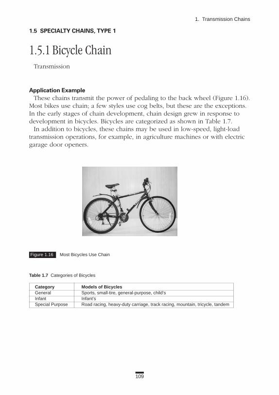
109
1. Transmission Chains
Figure 1.16 Most Bicycles Use Chain
1.5 SPECIALTY CHAINS, TYPE 1
1.5.1 Bicycle ChainTransmission
Application ExampleThese chains transmit the power of pedaling to the back wheel (Figure 1.16).
Most bikes use chain; a few styles use cog belts, but these are the exceptions.In the early stages of chain development, chain design grew in response todevelopment in bicycles. Bicycles are categorized as shown in Table 1.7.
In addition to bicycles, these chains may be used in low-speed, light-loadtransmission operations, for example, in agriculture machines or with electricgarage door openers.
Table 1.7 Categories of Bicycles
Category Models of BicyclesGeneral Sports, small-tire, general-purpose, child’sInfant Infant’sSpecial Purpose Road racing, heavy-duty carriage, track racing, mountain, tricycle, tandem

110
Applications
Construction and FeaturesBicycle Chains are generally categorized into two types: 1/2 3 1/8 and
1/2 3 3/32. The first number (1/2) is the chain pitch; the latter numbers (1/8and 3/32, respectively) indicate the inner width in inches.
Number 1/2 3 1/8 chain is used for simple transmission without speed shift-ing; it has the same construction as Standard Roller Chain.
Number 1/2 3 3/32 chain is used with a derailleur. There are two types ofconstruction—standard roller and bushingless (Table 1.8). In the bushinglesschain, the inner link plates are extruded so that the inner plates also serve asthe bushings (Figures 1.17 and 1.18). In most derailleur transmission chains,the link plates are bent or cut so that the chains can change smoothly on thefront or rear sprockets.
Figure 1.17 Bushingless Bicycle Chain Components
Figure 1.18 Schematic Diagram of Bushingless Bicycle Chain
Table 1.8 Applications of Bicycle Chains
Nominal Inner LinkNumber Pitch Width Construction Application1/2 X 1/8 12.7 3.30 Roller Chain Simple drive
General purpose1/2 X 3/32 12.7 2.38 Roller Chain With derailleur
Bushingless Chain Sports Racing
Outer Plate Inner Plate
Pin Roller

111
1. Transmission Chains
SprocketsThe basic sizes of the sprockets (front and rear) are common to all manufac-
turers; however, the tooth shape is different. This is especially true for thesprockets for 1/2 3 3/32 chains. Each manufacturer designs its own toothshapes for better shifting. Exercise care when changing sprockets.
Selection and Handling(1) Manufacturers usually offer a selection system for derailleur transmission,
which includes the chain and sprockets. Check the manufacturer’s catalog for information.
(2) The chain’s performance is usually influenced by wear. Select a chain with specially coated pins, which increase wear resistance.
(3) You must connect the chains carefully, or they may break during operation. Use special connecting pins (sold separately) to connect chains, especially those used with derailleurs.
(4) These chains are frequently exposed to rain, dirt, or mud, which can lead to elongation or rust. The chains need regular cleaning and lubrication.
(5) Do not use weak-acid rust remover (such as phosphatic rust remover) on these chains. These chemicals can cause hydrogen embrittlement and chain breakage.
Technical TrendTo keep up with the design enhancements of bicycles, chains are being
developed in several ways:(1) Lighter weight.(2) Higher rust and weather resistance.(3) Attractive appearance. (4) Nonstaining to clothes.(5) Lower noise at engagement.

112
Applications
1.5.2 Motorcycle ChainTransmission
Application ExamplesMotorcycles are high-speed applications that operate in tough conditions—
rain, dirt, sand, and high shock loads. These specially developed chains areused as the part of the drive train to transmit the motor power to the backwheel (Figure 1.19).
Motorcycle Chains are superior to gears, which are in the crank cases, by theease in adjusting the shaft center distance and the number of teeth of thesprocket. Therefore, you can freely design the motorcycle’s reduction ratiotaking into account the specifications and the working conditions. In the caseof a racing motorcycle, for example, the engine power may be 180 hp, andthe chain speed is 1,500 m/min.
Construction and FeaturesMotorcycle Chains have the same basic construction and sizes (numbers 40,
50, and 60, Table 1.9) as Standard Roller Chains. But they have a special widthof inner links. Because of the very demanding working conditions, some
Figure 1.19 Motorcycle Chain in Action

113
1. Transmission Chains
Motorcycle Chains have the following special features:(1) Strength
Quad-staked riveting on the pin head helps to retain the link plate on the pin. Connecting links are press fit. (Riveted connecting links are also available.) Link plates are thicker (heavy) and the rollers are seamless.
(2) Wear lifeSpecial coated pins, sintered bushings that are oil impregnated, and seam-less bushings with O-rings are used to extend the wear life of the chain.
(3) Resistance to dirt, sand, or mudTo prevent debris from getting into tight joints, the bushings are extend-ed beyond the inner link plates, and often O-rings are used to seal the chains. This extension and O-rings prevent abrasive material from getting into the chain.
(4) AppearanceThese chains may have special coloring, plating, (gold or silver), or glossy finish on the plates.
SprocketsSpecial sprockets are used for these chains. Numbers 425 and 530 sprockets
have the same tooth shapes as standard types.
Selection and Handling(1) Usually the specifications differ for each motorcycle or application, even
with the same-sized chains. Do not select the chain just by size of the sprocket; take into account the application. For example, an off-road motorcycle travels through dirt and sand, which will get on the chain. You should avoid the use of oil-impregnated sintered bushings for this application.
(2) Failure of Motorcycle Chains may result in injury or death. Care must be exercised when connecting or aligning the chains.
(3) Both O-ring chains and oil-impregnated sintered bushing chains wear rapidly if the O-rings fall off or if the oil in the sintered bushings is depleted. If either of these situations occur, the chain must be replaced—even if it has not elongated to the limit.
Table 1.9 Motorcycle Chains
40 Class 50 Class 60 Class
Chain Inside Chain Inside Chain InsideNumber Width (mm) Number Width (mm) Number Width (mm)
420 6.35 520 6.35 630 9.53425 7.95* 525 7.95428** 7.95* 530 9.53*
* Same inside width as ANSI Standard Roller Chain.** Roller diameter differs from ANSI Standard Roller Chain.

114
Applications
(4) The life of O-ring chain is usually determined by the durability of the O-ring. To improve the durability, there should be an oil film on theO-ring at all times. Even though it is a sealed chain, lubrication is required to extend the working life of the O-ring. Cleaning sprays may cause deterioration of the O-rings. Do not allow chains to air dry after washing, or to rust.
Technical TrendMotorcycles are getting faster and more powerful. Therefore, Motorcycle
Chains must have greater durability. At the same time, motorcycles are gettinglighter and smaller. Manufacturers are working on new materials, sizes, andheat treatments to improve the performance of the chain.

1.5.3 Chains for Automotive EnginesTransmission: Camshaft driving, balancer driving
Application ExamplesAutomotive Chains are used for driving the camshafts in engines, counterbal-
ance shafts, or oil pumps. Some manufacturers use cog belts instead of chainsin this application. (See Figure 1.20.)
Camshaft drives transmit the crankshaft rotation to the camshaft of the over-head cam (OHC) engine at a ratio of 2:1. The counterbalance shaft and oilpump are also driven by the crankshaft. Both of these drives are installedinside the engine and are not visible from the outside.
These chains work at the temperature range of -30˚ to 130˚C, and rotate atabout 600 to 7,000 rpm. Counterbalance drive sprockets rotate at 1,200 to14,000 rpm, which is equivalent to a speed of 1,800 m/min.! This is twice thespeed of engine drive chain. Motorcycles also use camshaft drives, but this dis-cussion is limited to automobiles that use roller chains, which are usuallyoffered by Japanese or European manufacturers. In the United States, SilentChains are usually used for camshaft drives in automobiles, but roller chainsare being increasingly used.
Construction and Features (1) Single strand chain with a pitch of 9.525 mm or 8.0 mm is usually used.
(See Figure 1.21.) In diesel engines or other high-load engines, double strand chains may be used.
(2) The chains are used at high speed. Therefore, the wear between the pins and bushings is the main concern. The surface of the pin is usually hardened with Hmv 1,600 or more.
115
1. Transmission Chains
Figure 1.20 Engine Cutaway to Show Chain Drive

116
Applications
Sprockets(1) Tooth shapes are either ANSI- or BS-type. Currently the BS-type is used
more frequently.(2) Automotive engines are produced on a large scale. The sprockets for
both the crankshaft and the camshaft are mass-produced from sintered metal.
Selection and Handling(1) These chains are used with chain guides, levers, and tensioners to
reduce chain elongation, vibration, and noise.(2) Generally, the chains are selected according to the transmission torque,
small-sprocket speed, and the layout. In mid- to high-speed transmission, vibration and lubrication must also be considered.
(3) These chains need forced lubrication.
Technical Trend Manufacturers are focusing attention on the following issues: (1) Making lighter-weight, smaller-sized chains.(2) Improving reliability of the entire transmission system, including
sprockets, guides, levers, and tensioners. (3) Decreasing noise from the chain, and throughout the entire drive system.
Figure 1.21 Automotive Drive Chain and Sintered Metal Sprockets

1.6 SPECIALTY CHAINS, TYPE 2
1.6.1 Miniature ChainTransmission: Office machines and general uses
Application ExampleMany users require “smaller, lighter” equipment. The transmission chains for
this equipment must also be smaller. Miniature Chains RS11SS (3.7465 mmpitch) and RS15 (4.7625 mm pitch) are designed to fill this request. (See thelower part of Figure 1.22.)
Construction and FeaturesThis is a bushing chain series, which means it does not have rollers. RS11SS
is made from 304 stainless steel; RS15 is made from carbon steel. Offset linksare not available for Miniature Chains.
SprocketsThere are special sprockets for RS11SS (tooth sizes of 12 through 48) and
RS15 (tooth sizes of 11 through 35). Sprockets for RS11SS are made of 304stainless steel; for RS15 they are carbon steel.
Technical TrendIn the case of small transmissions, toothed belts seem to have advantages
over chains.
117
1. Transmission Chains
Figure 1.22 Miniature Chain Versus Other Chains

118
Applications
1.6.2 Leaf ChainsLifting, counterbalance, forklifts, machine tools
Application ExamplesLeaf Chains are used for fork lift masts, as balancers between head and
counterweight in machine tools, or for low-speed pulling (tension linkage).This type of chain is also called “Balance Chain,” and is regulated by ANSIB29.8M, JIS B 1804, and ISO 4347. (See Figure 1.23.)
Construction and FeaturesThese steel chains have a very simple construction: link plates and pins. The
chain number indicates the pitch and the lacing of the links. (See Figure 1.24.)The chains also have the features shown below.
(1) High tensile strength per section area. This allows the design of smaller equipment.
(2) There are A- and B-type chains in this series. Both AL6 Series and BL6 Series have the same chain pitch as RS60 (19.05 mm), but they differ, as shown in Table 1.10.
(3) These chains cannot be driven with sprockets.
SprocketsSheaves, not sprockets, are used to change the direction of these chains
(Figure 1.25).
Figure 1.23 Leaf Chain and a Leaf Chain Application

119
1. Transmission Chains
Table 1.10 Difference Between AL6 Series and BL6 Series
AL6 Series BL6 SeriesPin Diameter 5.94 7.90Plate Thickness 2.4 3.2Plate Height 15.6 18.1Plate Lacing 2X2, 4X4 2X3, 3X4
Even lacing is standard. Odd lacing is standard.
Selection and Handling(1) In roller chains, all the link plates have higher fatigue resistance due to
the compressive stress of press fits. In Leaf Chains, only two outer plates are press fit. Therefore, the tensile strength of Leaf Chains is high, but the maximum allowable tension is low. Use safety guards at all times, and be particularly alert to assure that the safety factor is in the manufacturer’s catalog. Use extra safety factors where consequences of chain failure are severe.
(2) The more plates used in the lacing, the higher the tensile strength. But this does not improve the maximum allowable tension directly; the number of plates used may be limited.
Figure 1.24 Leaf Chain Lacing Patterns
2 x 2
2 x 3
AL622 AL644 AL666
BL623
LACING
LACING
CHAIN SIZE
CHAIN SIZE BL634 BL646
3 x 4 4 x 6
4 x 4 6 x 6

120
Applications
Figure 1.27 Leaf ChainFigure 1.25 Leaf Chain Sheave
Figure 1.26 Leaf Chain
(3) The pins articulate directly on the plates, and the bearing pressure is very high. The chains need regular lubrication. The use of SAE 30 or 40 machine oil is suggested for most applications.
(4) When the chain speed is greater than 30 m/min., or if the chain is cycled more than 1,000 times in a day, it will wear very quickly, even with lubrication. In either of these cases, use RS Roller Chains.
(5) AL-type should be used only under conditions in which:• There are no shock loads.• Wear is not a big problem.• Number of cycles is less than 100 a day. Under other conditions, BL-type should be considered.
(6) If you select a chain using a low safety factor, the stress in parts becomes higher. In this situation, if the chain is used in corrosive conditions, it may fatigue and break very quickly. If you’re operating under these conditions, perform maintenance frequently.
(7) The shape of the clevis depends on the type of end link of the chain (outer link or inner link). Manufacturers produce clevis pins or clevis connectors, but typically, the user supplies the clevis (Figures 1.26 and 1.27). The strands should be furnished to length by the manufacturer. An incorrectly made clevis may reduce the working life of the chain. Contact the manufacturer or refer to the ANSI standard.
(8) The sheaves are usually supplied by the user.
Clevis Connector
Clevis for Outer Link
Clevis Pin
Clevis for Inner Link

1.6.3 Inverted Tooth Chain (Silent Chain)Transmission
Application ExampleSilent Chains are used for the camshaft drive of the mid- to large-size
motorcycle engines and automobile engines in the United States, the transfer-case drive in four-wheel-drive vehicles, and the primary drivebetween the engine and transmission, as well as in other high-speed applications (Figure 1.28).
Construction and Features(1) Silent Chains have a very simple construction: only plates and pins.
Today’s Silent Chains are actually an update of a 19th-century design. ANSI B29.2M-1982 regulates the standard pitch, width, and kilowatt ratings of the chains and sprockets.
(2) There are eight different pitches from 9.52 mm to 50.8 mm. (3) The link plate receives tension and has a notch for engaging the
sprockets. There is no notch on the guide plate. These plates act as guides for the sprockets.
(4) Pins may be round or have other shapes, such as D-shape (Figure 1.29). (5) All of the chain components share the tension. Silent Chains have higher
capacity than roller chains of the same width.
121
1. Transmission Chains
Figure 1.28 Silent Chain

122
Applications
(6) Because the link plates of Silent Chain strike the sprocket at an angle, the impact and the noise are reduced (Figure 1.30). This is why these chains are called “silent.” The higher the chain speed, the greater the difference from roller chains.
SprocketsThe sprocket for Silent Chain is shaped like a gear. In the ANSI
standard, the tooth working face is a straight line. But in HY-VO® Chains (see Applications Series below), an involute tooth is used for the sprocket.
Selection and Handling(1) Silent Chains are good for high-speed transmission.(2) If single- or multiple-strand roller chains are an option, they are less
expensive. Wider Silent Chain becomes relatively competitive in price. (3) Silent Chains must be lubricated during operation. Use an oil bath if the
speed is less than 600 m/min. If the speed is more than 600 m/min., or if the shaft center distance is short, use a pump or forced lubrication. Silent Chains wear rapidly without lubrication.
(4) The notch on the plates can engage with the sprockets from only one direction. The chain is not for reversing applications.
(5) To select the right Silent Chain for your operation, refer to the manufacturer’s catalog.
Figure 1.29 Silent Chain Components Figure 1.30 Silent Chain Strikes the Sprocket at an Angle, Reducing Noise
LINK PLATE
GUIDE PLATE
PIN

123
1. Transmission Chains
Application SeriesHY-VO® Chain is a unique type of Silent Chain. HY-VO stands for HIGH
CAPACITY, HIGH VELOCITY, and INVOLUTE TOOTH, and it is a registeredtrademark of Borg-Warner Automotive, Inc.
In Silent Chain, the pin and the plate rotate against each other. In HY-VOChains, the pin is comprised of two pieces that have rotational contact. Due tothe rotational contact of the pins, the wear life of the chain is increased. Alsoin HY-VO Chains, the contact point between the pins moves up when thechain engages the sprocket (Figure 1.31). This construction decreases chordalaction (which was discussed in Basics Section 2.2.1), vibration, and noise.
Figure 1.31 HY-VO Chain
CONTACT POINT
PITCH LINE
PITCH LINE
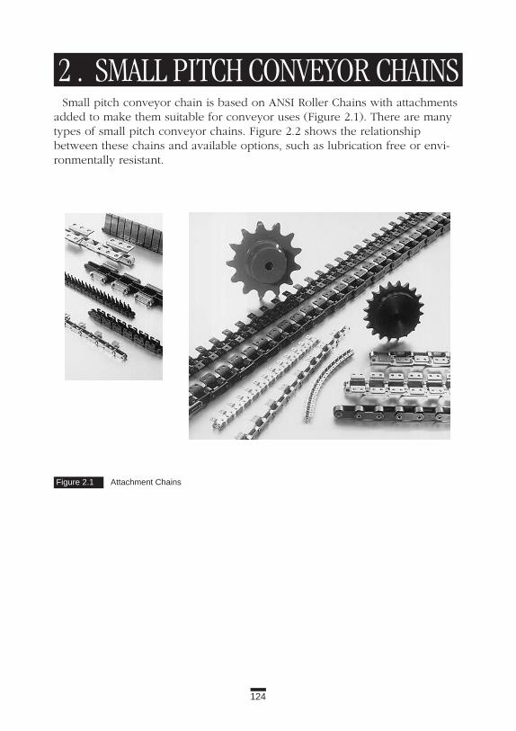
124
2 . SMALL PITCH CONVEYOR CHAINSSmall pitch conveyor chain is based on ANSI Roller Chains with attachments
added to make them suitable for conveyor uses (Figure 2.1). There are manytypes of small pitch conveyor chains. Figure 2.2 shows the relationshipbetween these chains and available options, such as lubrication free or envi-ronmentally resistant.
Figure 2.1 Attachment Chains

NOTE: 1) , Available.2) Heat resistant from -20°~400°C. Consult chain manufacturer in case
temperature exceeds these limits.3) AS Pins and bushings are precipitation-hardened. All others are
304 stainless.
125
2. Small Pitch Conveyor Chains
Figure 2.2 The Relationship Among Chains and Their Availability
Anti-CorrosiveNickelPlating Stainless
NP
LAMBDA®
LAMBDA®
Lube-Freebetween
Bushing andRoller
LAMBDA®
Lube-Free
RS AttachmentChain
RS Roller Chain
Hollow PinChain
RF Double Pitch
Plastic Roller
PlasticSleeve
HollowPin
Double PitchAttachment
Lube-Free
StandardStandardor Y/SY
SS AS
Hollow Pin
Hollow Pin
Engineered Plastic Inner Link
Attachment
Poly-SteelChain
LAMBDA®

126
Applications
2.1 SMALL PITCH CONVEYOR CHAINS FOR GENERAL USE
2.1.1 RS Attachment Chain Light conveyance: General uses
Application ExampleRS Attachment Chain is used for short conveyors (usually less than 10 m) of
small products. This chain is also suitable for conditions under which noiseshould be avoided (Figure 2.3).
Table 2.1 Standard Dimensions for RS Attachment Chain1
MaximumPitch Allowable
Chain No. (mm) Tension (kN) Note2
25 6.35 0.64 Bushed35 9.525 1.52 Bushed40 12.70 2.6550 15.875 4.3160 19.05 6.2780 25.40 10.6100 31.75 17.1120 38.10 23.9140 44.45 32.3160 50.80 40.9
1These dimensions are from Tsubaki. Other manufacturers’ products may vary.2Bushed chain is designed without a roller.
Figure 2.3 RS Attachment Chains

127
2. Small Pitch Conveyor Chains
Construction and FeaturesThis chain is based on Standard RS Roller Chain with added attachments for
conveyance, as indicated in ANSI B29.1 for reference.Table 2.1 shows the chain size, pitch, and maximum allowable tension for
standard products from Tsubaki. Among these chains, Numbers 40, 50, 60, and80 are used most frequently.
The features are shown below:(1) Due to the small pitch of these chains, the drive design is smaller.(2) Usually sprockets with a large number of teeth are used. Therefore,
the chain speed does not vary significantly, and the chain engages with sprockets with less noise.
(3) These chains may be used for high-speed conveyors.(4) A wide variety of standard attachments and special attachments
(Plus α Alpha series) are available for this chain series.(5) Slip-fit, spring-clip type connecting links are provided for RS40, RS50,
and RS60 chains. RS80 has cottered connecting links.
SprocketsStandard RS Roller Chain sprockets are used with these chains.
Selection and Handling(1) If the attachments receive large bending or twisting forces, make sure the
chain has adequate strength. In these conditions, Double Pitch Roller Chain or a chain with larger pitch will be more effective; both have larger attachments.
(2) Due to light weight, the chain inertia is smaller.(3) The tolerance of the overall chain length is -0.05 to 0.25 percent
(JIS Standard) of the standard length. This is greater than that of RS Roller Chain.
(4) In these chains, the clearance between the parts is small. Chain articulation is easily affected by dirt or contamination in the joints.
Application Series(1) Lubrication free: LAMBDA® series (operating temperature of
-10˚ to 60˚C). (2) Environmentally resistant: Special coatings or base materials may be
used to add extra resistance. These include:• Coating: Nickel plating, WP® specification.• Material: 304 stainless steel SS-type, AS-type with the pins, bushings,
and rollers made of precipitation-hardened stainless steel and the other components the same material as SS-type.

2.1.2 Double Pitch Roller Chain Light conveyance: General uses
Application ExampleThis is the most commonly used conveyor chain and is utilized widely in
the auto parts, electric, electronic, and precision machinery industries (Figure 2.4).
Construction and FeaturesDouble Pitch Roller Chain has the same basic construction as Standard Roller
Chain, but double pitch means the chain pitch is twice as long, has flat-shapedlink plates, and longer attachments. This series is regulated by ANSI B29.4,ISO 1275-A, and JIS B 1803. Table 2.2 shows the size, pitch, and maximumallowable tension for standard specification Double Pitch Roller Chain.
Among these, four sizes—Numbers 2040, 2050, 2060, and 2080—are mostcommonly used. The features are shown below:
(1) Double Pitch Roller Chains have the smallest tolerances for overall length compared to all other types of conveyor chains. Without attachments: 0 to +0.15 percent of the nominal chain length.With attachments: 0 to +0.25 percent of the nominal chain length.
128
Applications
Figure 2.4 Double Pitch Roller Chain
Table 2.2 Dimensions of Double Pitch Roller Chain1
MaximumPitch Allowable
Chain No. (mm) Load (kN)2040 25.40 2.652050 31.75 4.312060 38.10 6.272080 50.80 10.62100 63.50 17.12120 76.20 23.92160 101.60 40.9
1 These dimensions are from Tsubaki. Other manufacturers’ products may vary.

129
2. Small Pitch Conveyor Chains
(2) There are two types of rollers, R-roller (oversized) and S-roller (standard). The S-rollers are used in short-length and slow-speed conveyance. The R-rollers are most commonly used, especially forlonger conveyors.
(3) There are many standard attachments and special attachments (Plus αAlpha series) available for this series.
(4) Chains sized 2060 and larger have greater rigidity than Standard RS Attachment Chains because the link plates are one size thicker (heavy).
(5) Due to its light weight, the chain’s inertia is smaller.(6) Slip-fit, spring-clip-type connecting links are provided for Numbers 2040,
2050, and 2060. Number 2080 has cottered connecting links.
SprocketsSpecial sprockets are required for these chains. For the S-rollers, standard
sprockets exceeding 30 teeth are used (30-tooth sprocket has 15 effectiveteeth). The chain engages every second tooth.
Selection and Handling(1) Double Pitch Roller Chains are selected according to the allowable roller
load and maximum allowable tension.(2) When the attachments receive a large bending or twisting force, make
sure the chain has adequate strength. In these cases, a larger-pitch roller chain is frequently used because it has a thicker plate and longer attachment.
(3) In these chains, clearance between the components is small. Chain articulation is easily affected by dirt or contamination in the joints.
Application Series(1) Lubrication-free: LAMBDA® series (operating temperature of -10˚ to
150˚C). O-ring chains are also lubrication-free chains, however, they have bending resistance and sometimes, after engaging the sprockets, the chains retain the articulated position. This may occur at the return side of the chain loop. Therefore, O-ring chains are not suitable for conveyance.
(2) Environmentally resistant: Special coatings or base materials may be used to add extra resistance.
•Coating: Nickel plating, WP® specification.•Material: 304 stainless steel SS-type and AS-type with pins, bushings,
and small rollers are made of precipitation-hardened stainless steel.

130
Applications
2.1.3 Plastic Roller Plus Plastic Sleeve ChainTransmission, conveyance: Maintenance-free type, general uses
Application ExamplePlastic Sleeve Chain is used for general purpose with small loads, and under
conditions that require maintenance-free or low-noise applications.
Construction and FeaturesIn Plastic Sleeve Chains, the pins and bushings are separated by a sleeve
made of self-lubricating engineered plastic. This feature makes the chainsmaintenance free (Figures 2.5 and 2.6).
This chain has the features shown below:(1) A small coefficient of friction (R-Roller): 0.08 versus 0.12 for all-steel chain.(2) Light weight: 30 percent less than the weight of all-steel chain
with R-rollers.
Figure 2.5 Plastic Sleeve Chain
Figure 2.6 Plastic Sleeve Chain Versus Other Chains
Engineered Plastic S-or R-Roller
Engineered PlasticSleeve
Car
bon
Ste
elC
hain
Operating Hours
Wea
rE
lon
gat
ion
Lube
-Fre
eC
hain
Sta
inle
ssS
teel
Cha
in
Plastic Sleeve Chain

131
2. Small Pitch Conveyor Chains
(3) Low noise: the noise made from engaging the sprockets is 5 to 7 dB lower.
(4) In Plastic Sleeve Chain, the maximum allowable tension is one-sixth, and the allowable load of the R-roller is about one-third that of the same-sized all-steel chain (with lubrication).
SprocketsUse the same sprockets as for Double Pitch Roller Chain.
Application SeriesThere are special low-noise engineered plastic R-rollers, which can reduce
the noise from the standard engineered plastic type by 7 dB. The allowableroller load for low-noise R-rollers is about 30 percent less than standard engi-neered plastic R-rollers.

132
Applications
2.1.4 Hollow Pin Chain Conveyance, simplified attachment installation, general uses
Construction and FeaturesIn Hollow Pin Chain, the pin has a hole, allowing for the installation of
various attachments (Figure 2.7). Usually these chains are used for conveyors(Figure 2.8). Sizes are shown in Tables 2.3 and 2.4.
The advantages of installing attachments into the hollow pin include the following:
(1) The hollow pin is at the center of articulation, and always keeps the pitch length. Regardless of whether the chain is straight or wrapping around the sprocket, the center distance of attachments is always the same. Figure 2.8 shows an example of installing a mesh net. Even when the chains bend, the mesh net does not expand or contract.
Figure 2.7 Hollow Pin Chain
Figure 2.8 Installing Attachments
Can-dryer Rod
Crossrod with Mesh

133
2. Small Pitch Conveyor Chains
(2) With a crossrod over two chains, the load from the attachments is distributed to both sides of plates equally. The chain can fully use its strength and not twist.
(3) It is easy to change, maintain, and adjust attachments.
SprocketsStandard sprockets are used for the small pitch series. For double pitch
series, standard sprockets for Double Pitch Roller Chain are used.
Selection and Handling(1) These chains are selected using the same methods as other conveyor
chains. Care must be taken since the maximum allowable tension of hollow pin chains is less than that of the same-sized standard chains.
(2) Retaining rings are used on the pin head for connecting links. When an attachment link is to be added to an HP connecting link, the attachment link pin must be longer than those used in the rest of the chain.
(3) The pin is not riveted in this chain. The lower maximum allowable load and the high rigidity of the pin make it difficult for the link plates to come off.
(4) The small pitch series and the S-roller (standard) types in the double pitch series are bushing chains, which do not have rollers.
Table 2.3 Sizes for Hollow Pin Chain1
Pin Minimum MaximumInner Allowable
Chain No. Pitch Diameter (mm) Load (kN)RS40HP 12.70 4.00 1.76RS50HP 15.875 5.12 3.14RS60HP 19.05 5.99 4.21RS80HP 25.40 8.02 7.64
1These dimensions are from Tsubaki. Other manufacturers’ products may vary.
Table 2.4 Sizes for Double Pitch Hollow Pin Chain1
Pin Minimum MaximumInner Allowable
Chain No. Pitch Diameter (mm) Load (kN)RF2040HP 25.40 4.00 1.76RF2050HP 31.75 5.12 3.14RF2060HP 38.10 5.99 4.21RF2080HP 50.80 8.02 7.64
1These dimensions are from Tsubaki. Other manufacturers’ products may vary.

2.2 SPECIALTY CHAINS
2.2.1 Step (Escalator) ChainSmall size conveyance: Escalator
Application ExampleStep Chain, which is also called Escalator Chain, moves the steps on escala-
tors or drives moving sidewalks (Figure 2.9).
Construction and FeaturesIn escalators, the steps are installed about every 400 mm, however, widths
and heights are different. The tensile strength of step chains ranges from 6 to30 tons. The 9-ton type and 15-ton type are most common.
The chain pitch should be as small as possible to reduce the effects ofchordal action, which is caused by the chain/sprocket engagement. Using thesmallest size possible allows the chain to operate more smoothly (Table 2.5).
The way steps are installed on chains differs from country to country. InJapan, the bearing part is in the center of the chain plate, so the step shaft isinstalled there. In other countries, extended pins are used as the shaft for thestep (Figure 2.10).
134
Applications
Figure 2.9 Step (Escalator) Chain

135
2. Small Pitch Conveyor Chains
Figure 2.10 Bearing Hole and Extended Pin on Step (Escalator) Chain
Usually rollers on the step side carry the weight of steps and passengers, butin some types the chain rollers carry the weight.
The features of step chain are:(1) Greater wear resistance. The pin diameter is larger than standard chains.(2) Length from step to step and from chain to chain is strictly controlled.
SprocketsSpecial sprockets are required for step chains.
Technical TrendsThe chains shown above are being adapted for the following:(1) Lubrication-free type. (However, lubrication is mandated at regular
intervals.)(2) Low-noise type (for quiet environments).
Table 2.5 Pitch and Attachment Spacing for Step (Elevator) Chain
AttachmentPitch (mm) Spacing
Small Size 67.7 6thMedium Size 81.3 5thLarge Size 101.6 4th

Figure 2.11 ATC Chain Can AccomodateMany Tools
Figure 2.12 ATC Chain
HP-Type
SK-Type
136
Applications
2.2.2 ATC ChainSmall conveyance: Machine tools
Application ExampleATC Chain is used to organize tools in the automatic tool changer, which is a
device on Computer Numeric Control (CNC) machine tools.When fewer than 30 tools are used, the tool pots are mounted on a disc.
Tools are changed by controlling the disc. When more than 30 tools are used,tool pots are mounted directly on the chain. (See Figures 2.11 through 2.13.)
Comparing the disc and chain set-ups, differences include the following points:
(1) Using the same area, the chain type can have as much as 1.5 times as many tools as that of the disc (Figure 2.13).
(2) To add tools to the disc type, you must change to a larger-diameter disc and redesign the changer. But with the chain type, you simply add chain strands. The changer location remains the same, allowing standardization. (See Figure 2.14.)
Figure 2.13 Chain-Type ATC Can Have 1.5 Times that of Disc-Type ATC
Disc-Type ATCChain-Type ATC

137
2. Small Pitch Conveyor Chains
Figure 2.14 Ways to Add Tools
Construction and FeaturesThere are two types of ATC Chains: SK and HP. Note the following features:SK series has two strands of chain in which the pitch of the outer link and
inner link is different. SK attachments are placed on every other link. Thereare three standard tool pitches: 95.25, 114.30, and 133.35 mm, which are basedon RS100, 120, and 140 transmission chains, respectively. The SK series canbend in only one direction.
HP series has large-diameter hollow pins. There are five standard tool pitches:90, 100, 130, 140, and 160 mm. HP series can bend in both directions, whichpermits more freedom in design.
Both types of chain are available for any shank number, including 40 and 50in MAS, ANSI, and ISO types. Special ATC Chains are also available for 25, 30,35, 45, and 60; check with the manufacturer.
SprocketsThe SK series ATC Chain uses the sprockets that are used for duplex power
transmission roller chain. (The tooth range is limited.) HP series ATC Chainrequires special sprockets.
Selection and Handling(1) ATC Chains must be lubricated.(2) When there is excessive tool overhang, use a tool guide to keep
the chain straight.(3) Change tools at the position shown in Figure 2.15.(4) Positioning pins and grippers help to maintain accurate placement.
For Expansion of Number of Tools
Chain-Type ATC
Disc-Type ATC Tool Replacement Position

138
Applications
Figure 2.15 Positions for ATC Tool Changers
Gripper
Positioning Pin
GripperPositioning Pin
Gripper
Positioning Pin
Sprocket
ATC Chain
ATC Chain
ATC Chain

139
2. Small Pitch Conveyor Chains
2.3 Standard AttachmentsMost applications use small pitch conveyor chains with attachments in
one of these ways:• Convey materials directly on chain attachments.• Convey materials on jigs installed on the attachments.The characteristics of the conveyed materials and the working environment
are different for each application. Many types of attachments with and withoutjigs are available.
There are many different types of attachments; it would be difficult for chainmanufacturers to satisfy all customer requirements for quality, price, and deliv-ery if every type of special attachment chain were made. There are too manyvariations. Chain manufacturers need mass production to maintain high quali-ty, reasonable prices, and quick delivery, not small production lots of manydifferent items.
Current standard attachments are established and selected based upon thelong history of attachment chain use and demand, and they provide high qual-ity, economy, and quick delivery to meet the majority of customers’ require-ments. For small pitch conveyor chains, standard attachments include: A, K,SA, SK, D-1, and D-3 types.
Standard attachments are available for a wide variety of chains:• With special surface treatments (nickel-plated or WP®).• Made of 304 stainless steel or other metals.• For lube-free operations (LAMBDA® series, etc.).In the following sections, we will explain each standard attachment.
2.3.1 A AttachmentAn A attachment is most commonly used. It has a bent link plate that
extends out on one side of the chain, forming an L-shape. It comes with oneor two bolt holes, which are referenced A-1 or A-2, respectively (Figure 2.16).The attachment interval can vary (for example, on each chain link, every fivelinks, or two attachments in a series with intervals every four links, etc.).Generally two strands of chains with slats are used (Figure 2.17).

140
Applications
Attachments are subjected to bending force. If they convey heavy objects,have long jigs installed, or receive side loads, twisting force is added to thebending force. Depending on the application, make sure you consider theseforces in your calculations.
The shape of the attachment influences the design of the equipment. If slatsdo not cover the chain rollers, guide rails may be used to support the chain rollers on the return side.
2.3.2 K Attachment This is an attachment made by installing A attachments on both sides of the
chain. The attachment is called K-1 or K-2 based on the number of bolt holeson one side. The attachment interval can vary the same as the A attachment(Figure 2.18).
Figure 2.16 A-2 Attachment Figure 2.17 A-2 Attachment with Slat
Figure 2.18 K-1 Attachment
Installation of Slat

The top of the attachment is higher than the R-rollers, so slats or jigs can beinstalled over the chains (Figure 2.19). Objects can also be conveyed directlyon the K attachments.
NOTE: When the bushings and rollers wear extensively, the upper sideof the rollers may touch the slats or jigs. Larger than standard over-sized rollers or flanged F-rollers may cause interference with the slat orjigs. Please check with the chain manufacturer.
When a wide slat is installed on two A attachment chains, the slats may notbe able to support the weight. A chain with K attachments is installed betweenthe A attachment chains to help support the load (Figure 2.20).
When the slats are rigid enough and are fastened well to the attachments,there is almost no effect from bending force to the strength of the attachment.But if the slat is not fastened well, make sure to consider the bending force inyour calculation.
If long jigs are installed, or the attachment receives side loads, it is exposedto twisting forces.
The return side of the K attachment chain cannot be supported with guiderails on the rollers. The return may be slack or supported in some other way(Figure 2.21).
2.3.3 SA AttachmentFor the SA attachment, the link plate is extended on one side of the chain,
and one or two bolt holes are installed. These are called SA-1 or SA-2 depend-ing on the number of the bolt holes (Figure 2.22). The attachment interval canvary the same as the A attachment. These attachments may be adapted for usewith hooks or slats (Figure 2.23).
The SA attachment is simpler and stronger than the A attachment, and mayreceive bending and twisting force depending on the direction of the loads.
The return side of the chains can be supported by guide rails on the rollersunless bolts extend into the attachment.
141
2. Small Pitch Conveyor Chains
Figure 2.20 Using A and K Attachments Figure 2.21 K Attachment Configuration (Note return side.)
Take-up
Drive
Figure 2.19 K Attachment with Jigs
Installation of Bucket Installation of L-angle

142
Applications
2.3.4 SK AttachmentSK attachments are made by installing SA attachments on both sides of the
chain. They are called SK-1 or SK-2, depending on the number of bolt holeson one side. The attachment interval can vary the same as the A attachment(Figure 2.24).
Usually SK attachments are used with dogs or jigs (Figure 2.25). SK attach-ments are strong enough to stand up to bending or twisting forces.
The return side of SK attachment chains cannot be supported by guide railson the rollers like A or SA attachment chains. The return must be slack or sup-ported in some other manner.
Figure 2.22 SA-2 Attachment
Figure 2.24 SK-1 Attachments Figure 2.25 SK Attachments May Be Used with Dogs or Jigs
Figure 2.23 SA Attachments Are Adaptable for Use with Hooks or Slats
Double Strands Convey Long Materials
Installation of Hook
Installation of Pusher
Installation of V-block

143
2. Small Pitch Conveyor Chains
Figure 2.26 D-3 Attachment (Extended Pin)
Figure 2.27 D Attachments with Crossrods and Jigs
2.3.5 D Attachment (Extended Pin)In this form, the one end of the pin is extended. The attachment interval
can vary the same as the A attachment (Figure 2.26).As shown in Figure 2.27, two sets of D attachment chains can be connected
to crossrods, or jigs (such as blocks) may be installed.The extended pins are subjected to bending and shearing forces. The allow-
able load of D attachment that is shown in a manufacturer’s catalog is basedon a bending force concentrated at the center of the extended pin.
The return side of the D attachment chain can be supported by guide railson the rollers.

144
Applications
2.4 Plus α Alpha Attachments Plus α Alpha attachments are the second most frequently used type of
modified attachments. These attachments are sorted into three types:(1) Hole diameter in an A or K attachment or the length
of the pin in a D attachment (Figures 2.28 and 2.29). (2) Installing a nut in the hole of an A or K attachment (Figure 2.30).(3) Using a different type of attachment (Figures 2.31 (i) and (ii)).
Types (1) and (2) are easy-to-order products. Type (3) includes specialdesigns that are available for the convenience of equipment designers. Thesedesigns can be used whenever possible for equipment.
Plus α Alpha attachments are available in the following types of chains: (1) Special surface treatment (nickel-plated, WP®).(2) Made of 304 stainless steel or other metals.(3) Lube-free (LAMBDA® series or other type).
Figure 2.29 Changing the Pin Length in D Attachments
Figure 2.30 Installing a Nut in an A or K Attachment
Figure 2.28 Changing the Hole Diameter in A or K Attachments
A Attachment
D Attachment
K Attachment
A Attachment K Attachment

Spec Rubber pads Improved wear Easy lateral Smaller gap For bottling Excellentprevent resistance. transfer of between the and canning for damage to conveyed plates. industries. conveyingthe conveyed objects. relativelymaterials. heavy
goods.
Spec Conveying Sharp-top Press-fitted Gripping The chain Rubberbar-type attachment bushing is attachment bends in one padsobjects. is ideal for ideal for for thin direction only. hold the
conveying bearing. objects, such conveyedboard-type as film. materialobjects. from above
and below.
Spec The upper Attachment Side plate is Inner bent HP chain with Curved surface of the for larger sizes higher than attachments attachment. chain withlink plate has over RS180. the top of are chamfered attachmentbeen ground the roller. to protect and guideto provide a conveyed plate.smooth con- materials.veying surface.
145
2. Small Pitch Conveyor Chains
Figure 2.31 (i) Other Types of Attachments
Type Ground Large chain Double pitch Internally bent Hollow Curved attachment. attachment with deep attachment. pin with attachment
(over RS180). link. attachment. with guideplate.
Type Triangle Sticker Bushing Grip No-bend Rubberattachment. attachment. attachment. attachment. attachment. attachment.
Type Rubber pad. Heat-treated Bent-end Inclined Crescent plate. Slattop plate. top plate. top plate. attachment.
Symbol PG RS RFD UM HP GP
Attachment Series (1)
Attachment Series (2)
Top Plate, Slat Attachment
Symbol RE FS AB KU NB RSG
Symbol PSG YP SM CT CL SLT

Spec Thread Install tool Suitable for for tool attachment conveyingattachment with clips. on the pins.with nuts.
146
Applications
Figure 2.31 (ii) Other Types of Attachments
2.5 Special AttachmentsThese made-to-order products require careful consideration. Should a
manufacturer supply them, or should you make them in house? Here are some points to weigh:
High Accuracy The most common requirement is the height from the guide rail to the upper
edge of the A or K attachment. The “ground upper surface” type of Plus αAlpha attachments has high accuracy. The tolerance is approximately 0.2 mm,depending on the chain size and manufacturer. For standard attachments, the tolerance range is wider: about two to three times that of the Plus α Alphaattachments. During normal service, the chain will wear, and the height will change.
Type Guide HP with guide Curved chain Threaded Extended pin Stay-pin.roller. roller. with guide extended with clip.
roller. pin.
Type Double Top roller OBR withstrand with guide attachmenttop roller. attachment. guide.
Spec Wide-top For longer For longerroller width. conveyor line. conveyor line.
Symbol GR HP-GR CU-GR EN EC ST
Guide Roller Attachment
Free Flow Chain
Symbol TR TG SG
Guide roller prevents meandering.

147
2. Small Pitch Conveyor Chains
If you require greater accuracy than is available from Plus α Alpha attachments, make a shuttle that supports the conveyed objects, and use chains only for tracking.
When you need high accuracy in other dimensions besides height, contactthe chain manufacturer.
Cost The reason chain manufacturers can produce attachments at low cost is that
they use a punch-press process, which is efficient but takes time to set up. To absorb the cost of set-up, parts need to be produced in large quantity: hun-dreds of pieces. (The smaller the part, the more parts needed to offset the set-up costs.)
If you need a special attachment in low quantities, the chain manufacturercan help work out a design that can be produced at lower cost.
Turnaround Time Chain manufacturers can supply almost all the standard attachments from
stock. Special order attachments require lead times. The lead time for specialtyattachments runs from several weeks to several months. To prevent a crisis sit-uation, in the event of normal wear or catastrophic failure, you should stockreplacement chain and re-order well in advance. Figure 2.32 shows severalexamples of specialty attachment chains that can be made.

148
Applications
Figure 2.32 Specialty Attachments
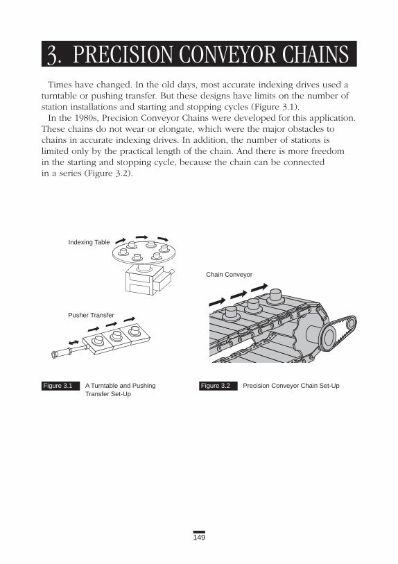
149
Figure 3.1 A Turntable and Pushing Transfer Set-Up
Figure 3.2 Precision Conveyor Chain Set-Up
3. PRECISION CONVEYOR CHAINSTimes have changed. In the old days, most accurate indexing drives used a
turntable or pushing transfer. But these designs have limits on the number ofstation installations and starting and stopping cycles (Figure 3.1).
In the 1980s, Precision Conveyor Chains were developed for this application.These chains do not wear or elongate, which were the major obstacles tochains in accurate indexing drives. In addition, the number of stations is limited only by the practical length of the chain. And there is more freedom in the starting and stopping cycle, because the chain can be connected in a series (Figure 3.2).
Indexing Table
Chain Conveyor
Pusher Transfer

3.1 Bearing Bush Chain Light to heavy conveyance: No elongation, electric, electronic, precision
machinery industries
Application ExamplesBearing Bush Chain (Figure 3.3) is used in automatic assembling, packaging,
filling, and parts installation for a variety of industries, including electric, elec-tronic, semiconductor, automobile, and food as well as in other precisionmachinery. It includes the following features:
(1) High accuracy and no elongation. (2) Interchangeability with other double pitch roller chains and
large pitch conveyor chains.(3) Low cost.
Constructions and Features Usually chains are designed with gaps between the pins and bushings for
proper operation. With Bearing Bush Chain, needle bearings are installedbetween the pins and bushings. These add rolling elements between thesecomponents and eliminate the sliding friction (Figure 3.4).
The advantages of this design include:(1) Immediately after installation, the chain stretches a little (less than 0.03
percent) to fit the contacting surface of chain parts. After that, it doesn’t stretch (Figure 3.5). The results include the following points:
150
Applications
Figure 3.3 Bearing Bush Chain
Figure 3.4 Needle Bearings in Precision Chain
Profile of Bearing Portion
Bushing
Needle Bearing
Roller
Pin
Lubricated Between Pin and Bushing

151
3. Precision Conveyor Chains
Figure 3.5 After Installation, Precision Chain Has No Elongation
ii) No annoying position-adjustment maintenance.iii) No take-up adjustment or lubrication.
(2) The main dimensions are the same as double pitch roller chain and large pitch conveyor chain (R-rollers). That gives you the following benefits:i) Change from standard chains to Bearing Bush Chains with
minimal redesign of the equipment.ii) Low-cost standard sprockets can be used (special made-to-order
sprockets are required for high accuracy).iii) Available with a variety of attachments.
(3) Relatively low cost.Bearing Bush Chain has many sizes from small to large (Table 3.1).
SprocketsFor double pitch roller chain type, standard sprockets are used for general
applications. When the application requires high accuracy, special-ordersprockets are needed.
For Engineering Class conveyor chains, machined-tooth sprockets (made toorder) are used instead of standard flame-cut sprockets.
Table 3.1 Precision Conveyor Chain
Double Pitch Chain Maximum Engineering Class Chain MaximumAllowable Allowable
Chain No. Load (kN) Chain No. Load (kN)RFN2040R 0.78 RFN03075R 2.45RFN2050R 1.27 RFN05100R 4.90RFN2060R 1.76 RFN10150R 7.85RFN2080R 2.94 RFN12200R 9.81
RFN17200R 12.70RFN26250R 19.60RFN36300R 24.50
Cha
inW
ear
Elo
ngat
ion
(%)
Number of Cycles
Standard Type and High-Precision Type
i) Accurate positioning in a high-speed or indexing drive. For example, in an application of automatic installation of electronic parts with 30 stations, a conveying speed of 10 m/min., and an index of 0.6 sec-onds, the positioning accuracy is ± 0.2 mm (using a positioning pin).

152
Applications
Points of Selection and Handling(1) In Bearing Bush Chain, the contacting surfaces between pins and
needles or needles and bushings are small. If these parts are subjected to a load larger than the allowable static load of the needle bearing, permanent deformation will occur, and the chain will not operate correctly. The chain tension, including inertia, should be lower than the rated allowable load.
(2) Due to the low bending resistance, the chains will vibrate at the low-tension return side. Guide rails or guide rollers help to prevent vibration.
(3) A “high-precision type,” which is more accurate in the overall chain length and the dimension of attachments, is available.
(4) The double pitch chain type is basically an inch-pitch series, but there are some metric pitches available.
Application SeriesLink plates of Bearing Bush Chain are nickel-plated to avoid rusting
in indoor use. Stainless steel Bearing Bush Chain is available for corrosive conditions.
However, the allowable load is limited because of the low hardness of thecontacting parts. In addition, the chain will elongate gradually (Figure 3.6).
Heat-resistant Bearing Bush Chain is available for temperatures up to 150°C.
Figure 3.6 Elongation of Stainless Steel Precision Chain
Cha
inW
ear
Elo
ngat
ion
(%)
Number of Cycles
Stainless Steel Bearing Bush Chain

153
3. Precision Conveyor Chains
3.2 Indexing Table Chain Precision conveyance: High accuracy, no elongation Electric, electronic, and precision machinery industries
Application ExamplesIndexing Table Chain is used when you need a more accurate conveyance
than Bearing Bush Chain, for example, in an assembling machine with 46 stations, a speed of 10 m/min., an index of 1.0 second, and a stopping accuracy of ± 0.15 mm.
Construction and FeaturesIndexing Table Chain is expensive because each link has seven needle
bearings (Figure 3.7). This chain includes the following features:(1) No elongation.(2) Each part is measured with precision; the installing accuracy is ± 0.1 mm.(3) The chain pitch is indicated in millimeters.(4) Four sizes are standard: 50 to 150 mm with a maximum allowable
tension between 0.49 and 1.27 kN.
SprocketsSpecial sprockets with 8 or 12 teeth are required.
Figure 3.7 Indexing Table Chain
Positioning Line for Attachment
Direction of Travel

154154
Figure 4.1 Top Chains
4. TOP CHAINS
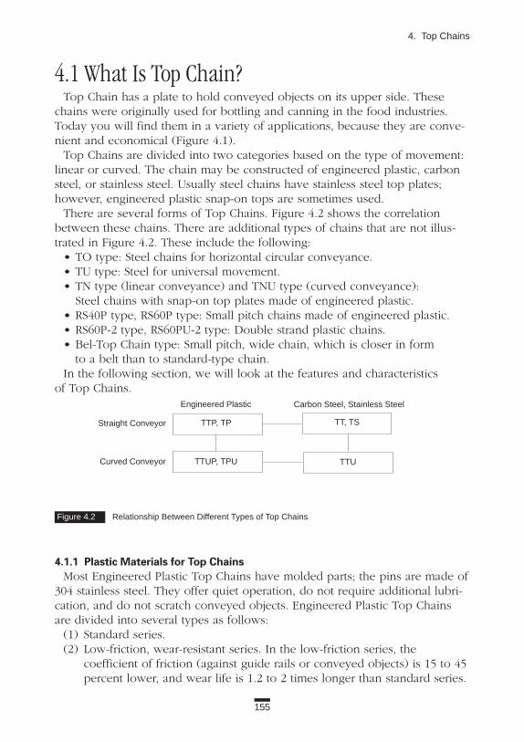
4.1 What Is Top Chain?Top Chain has a plate to hold conveyed objects on its upper side. These
chains were originally used for bottling and canning in the food industries. Today you will find them in a variety of applications, because they are conve-nient and economical (Figure 4.1).
Top Chains are divided into two categories based on the type of movement:linear or curved. The chain may be constructed of engineered plastic, carbonsteel, or stainless steel. Usually steel chains have stainless steel top plates;however, engineered plastic snap-on tops are sometimes used.
There are several forms of Top Chains. Figure 4.2 shows the correlationbetween these chains. There are additional types of chains that are not illus-trated in Figure 4.2. These include the following:
• TO type: Steel chains for horizontal circular conveyance.• TU type: Steel for universal movement.• TN type (linear conveyance) and TNU type (curved conveyance):
Steel chains with snap-on top plates made of engineered plastic.• RS40P type, RS60P type: Small pitch chains made of engineered plastic.• RS60P-2 type, RS60PU-2 type: Double strand plastic chains.• Bel-Top Chain type: Small pitch, wide chain, which is closer in form
to a belt than to standard-type chain.In the following section, we will look at the features and characteristics
of Top Chains.
4.1.1 Plastic Materials for Top ChainsMost Engineered Plastic Top Chains have molded parts; the pins are made of
304 stainless steel. They offer quiet operation, do not require additional lubri-cation, and do not scratch conveyed objects. Engineered Plastic Top Chainsare divided into several types as follows:
(1) Standard series.(2) Low-friction, wear-resistant series. In the low-friction series, the
coefficient of friction (against guide rails or conveyed objects) is 15 to 45 percent lower, and wear life is 1.2 to 2 times longer than standard series.
155
4. Top Chains
Figure 4.2 Relationship Between Different Types of Top Chains
Carbon Steel, Stainless SteelEngineered Plastic
TTP, TP
TTUP, TPU
TT, TS
TTU
Straight Conveyor
Curved Conveyor

156
Applications
(3) Heat-resistant, high-speed series. When constructed of super engineered plastic, this series can work continuously in temperatures up to 250°C, and the chains can convey objects with speeds up to 200 m/min.
(4) Anti-chemical series. These chains are made of super engineered plastic and resist most organic solvents, inorganic salts, acids, alkalines, and oxidizers. There is a “super anti-chemical” series with pins made of titanium.
(5) Electroconductive series. This series has electric resistivity of 106 Ω•cm. These chains are suitable where dust collection, electronoise, and elec-trosparks should be avoided.
(6) Plastic pin series. In this series, chains and pins are made of engineered plastic. Compared to the standard series, these chains are 15 to 25 percent lighter in weight and are easy to disassemble for recycling. A larger-diameter pin and unique design make this a very strong series. In fact, it has almost the same allowable tension as the standard series.
Table 4.1 shows the features of each type of TPU 836 chain. Coefficient of fric-tion and maximum allowable load are under the following conditions: roomtemperature, non-lubricated, chain speed 10 m/min., and stainless steel rail.
4.1.2 Guide Rail Materials The guide rails for engineered plastic chains are usually made of 304 stain-
less steel with a good finish, MC nylon, or ultra-high molecular-weight poly-ethylene (UHMW). For steel chains, guide rails are made of plastic.
For heat-resistant and high-speed applications, make sure you consider thefollowing points:
(1) When the chain operates within normal temperatures at high speeds, choose a guide rail that is made of carbon steel or stainless steel with polished, hard chrome-plating.
(2) When the chain operates in high temperatures, consider a polished stainless steel guide rail. Remember to allow for heat expansion, and fix only one end of the guide rail.
Table 4.1 Types of Engineered Top Chains
Maximum Maximum Coefficient MaximumChain Speed Ambient of Allowable
Material (m/min.) Temp. (°C) Friction Load (kN)Standard Polyacetal 50 80 0.25 0.98Low-Friction Special Polyacetal 50 80 0.17 0.98Heat-Resistant Super Engineered Plastic 200 250 0.20 0.98Anti-Chemical Super Engineered Plastic 40 80 0.30 0.50Electroconductive Special Polyacetal 50 80 0.25 0.70Plastic Pin Special Polyacetal 50 80 0.17 0.88

157
4. Top Chains
4.1.3 LubricationSoapy water used to be applied as a lubricant in food industries, but now a
water-based lubricant is more frequently utilized. For general applications thatallow oil, use oil to lubricate Top Plate Chains.
4.1.4 Various AccessoriesIn addition to the chains and sprockets explained in this book, there are a
variety of accessories, including guide rails, chain guides, and feet (Figure 4.3).
Figure 4.3 Chain Accessories
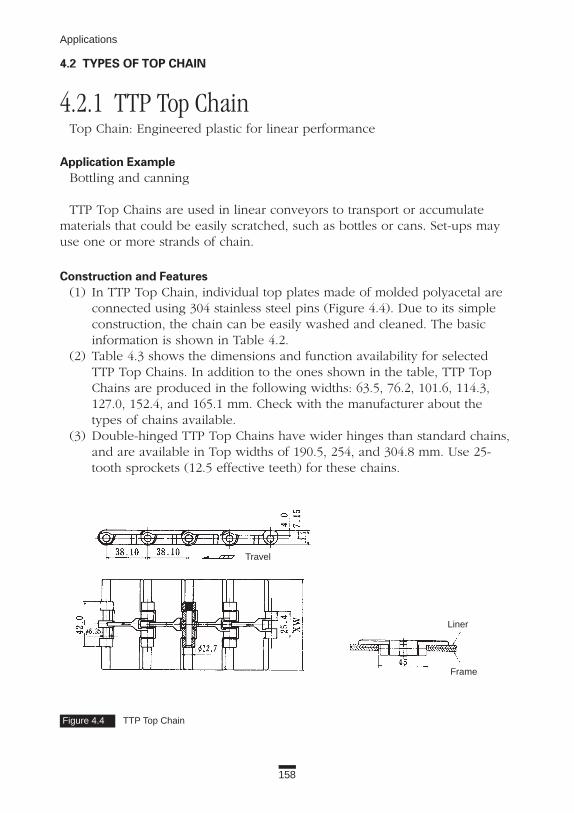
158
Applications
4.2 TYPES OF TOP CHAIN
4.2.1 TTP Top Chain Top Chain: Engineered plastic for linear performance
Application Example Bottling and canning
TTP Top Chains are used in linear conveyors to transport or accumulatematerials that could be easily scratched, such as bottles or cans. Set-ups mayuse one or more strands of chain.
Construction and Features(1) In TTP Top Chain, individual top plates made of molded polyacetal are
connected using 304 stainless steel pins (Figure 4.4). Due to its simple construction, the chain can be easily washed and cleaned. The basic information is shown in Table 4.2.
(2) Table 4.3 shows the dimensions and function availability for selected TTP Top Chains. In addition to the ones shown in the table, TTP Top Chains are produced in the following widths: 63.5, 76.2, 101.6, 114.3, 127.0, 152.4, and 165.1 mm. Check with the manufacturer about the types of chains available.
(3) Double-hinged TTP Top Chains have wider hinges than standard chains, and are available in Top widths of 190.5, 254, and 304.8 mm. Use 25-tooth sprockets (12.5 effective teeth) for these chains.
Figure 4.4 TTP Top Chain
Travel
Liner
Frame

Table 4.3 Top Plate Dimensions
Top Plate Low- Heat- Anti-Width (mm) Standard Friction Resistant Chemical Electroconductive Plastic Pin
82.6 N/A
Consult 114.3 N/A Manufacturer
Consult 190.1 N/A Manufacturer
Table 4.2 Profile of TTP Top Chain
SprocketBushing Maximum
Chain Pitch Diameter Allowable Number Outer Diameter(mm) (mm) Load (kN) of Teeth P.C.D. Steel Plastic of Idler Wheel
9.5 117.33 N/A38.1 12.7 0.83 10.5 129.26 130
11.5 141.22 142.512.5 153.20 154.5
(Segmented)
159
4. Top Chains
SprocketsUse special sprockets for TTP Top Chain. Chains may slide off the steel
sprocket due to uneven load distribution or misalignment. There are optionalguide rings for steel sprockets to prevent this. Engineered plastic sprocketshave integral guides at every tooth, or every second tooth.
An engineered plastic idler pulley may be substituted for the sprocket at the tail shaft. The idler pulley rotates freely, without bearings, on the fixedsteel shaft.
NOTE: Excessive chain tension can damage the idler pulley.
: Available

160
Applications
4.2.2 TP Top Chain Top Chain: Engineered plastic for linear conveyance
Application ExampleTP Top Chains are used for linear conveying. Applications are similar to the
TTP series (Figure 4.5).
Construction and Features(1) There are two specifications of TP Top Chain: Type I and Type II.
If you are developing a new application, consider Type II Chain (Figure 4.5). It offers higher wear resistance than Type I.
(2) Tables 4.4 and 4.5 show the main characteristics and available top-plate widths for different chain series.
Figure 4.5 TP Top Chain (Type II)
Travel

161
4. Top Chains
SprocketsFor TP Type II Top Chains, use spockets for TTU type. Twelve-tooth split
sprockets made of engineered plastic (P.D. 147.21) are also available.An engineered plastic idler pulley may be substituted for the sprocket at the
tail shaft. The idler pulley rotates freely, without bearings, on the fixed steelshaft.
NOTE: Excessive chain tension can damage the idler pulley.
When operating in high temperatures, use steel sprockets. If the temperatureis higher than 150°C, contact the manufacturer.
Chains for Special ApplicationsRS2040P chain series, with a top plate width of 50 mm, has a pitch of 25.4 mm.
This is smaller than standard Top Plate Chain, which has a pitch of 38.1 mm.With RS2040P, you can use smaller sprockets with 19 teeth (9.5 effective teeth,P.D. 78.23) and select a base material that meets the specific operating conditions,for example, electroconductive, chemical-resistant, super chemical-resistant, orheat-resistant.
Table 4.4 TP Top Chain and Sprockets
Bushing Maximum SprocketChain Pitch Diameter Allowable Number
(mm) (mm) Load (kN) of Teeth P.C.D. Steel Plastic10 123.29 N/A
12.7 (Type I) 10.5 129.2638.1 15.2 (Type II) 1.181 11 135.23 N/A
12 147.2113 159.20 N/A
1Refer to manufacturer’s catalog for Heat-Resistant series data.
Table 4.5 TP Top Chain Special Feature Availability
Top PlateWidth (mm) Standard Low-Friction Heat-Resistant Anti-Chemical Plastic Pin
76.2 N/A N/A82.6 N/A / N/A /
N/A / Consult 101.6 N/A / N/A / N/A Manufacturer N/A
N/A / Consult 114.3 N/A / N/A / N/A Manufacturer N/A
N/A / Consult127.0 N/A / N/A / N/A Manufacturer N/A
Note: Two symbols in one cell stand for Type I / Type II. : Available

162
Applications
4.2.3 TTUP Top Chain Top Chain: Engineered plastic for curved conveyance
Application Example Bottling, canning, and general uses
One or more strands of TTUP Top Chains are used for conveying or accu-mulating objects that are easily scratched, for example, bottles, cans, and fine-ly machined parts.
Construction and Features(1) TTUP Top Chain is based on engineered plastic TP Top Chain, Type II,
but it has extra side-flexing capability. It can curve around corners with minimum radius (R) of 600 mm. This is accomplished with tapered knuckles.
(2) There are no float-prevention tabs on links of TTUP Top Chain (Figure 4.6).
(3) Tables 4.6 and 4.7 show the main functions and available top plate widths for different chain series.
Figure 4.6 TTUP Top Chain
Travel

Table 4.7 TTUP Top Chain Special Feature Availability
Top Plate Low- Heat- Anti-Width (mm) Standard Friction Resistant Chemical Electroconductive Plastic Pin
82.6 N/AConsult N/A
114.3 N/A Manufacturer N/AConsult
190.1 N/A Manufacturer N/A
163
4. Top Chains
SprocketsAn engineered plastic idler pulley may be substituted for the sprocket at
the tail shaft. The idler pulley rotates freely, without bearings, on the fixedsteel shaft.
NOTE: Excessive chain tension can damage the idler pulley.
Selection and HandlingThe main difference between TTUP and TPU Top Chain is that TTUP does
not have float-prevention tabs. Therefore, TTUP may be more easily detachedfrom guide rails.
Table 4.6 TTUP Top Chain and Sprockets
Chain Bushing Maximum SprocketPitch Diameter Allowable Number Outer Diameter of(mm) (mm) Load (kN) of Teeth P.C.D. Steel Plastic Plastic Idler Wheel
10 123.29 N/A N/A10.5 129.26 130
38.1 15.2 1.08 11 135.23 N/A 142.512 147.21 154.5
(Split is available)
13 159.20 N/A N/A
: Available

164
Applications
4.2.4 TPU Top Chain Engineered Plastic Top Chain for curved conveyance
Application Example Bottling, canning, and general usesTPU Top Chain (Figure 4.7) is used in similar applications as TTUP Top Chain.
Construction and Features(1) TPU Top Chain has side-flexing capability with a minimum radius (R) of
500 mm accomplished by taper-shaped knuckles, and is equipped with float-prevention tabs on plates. A smaller minimum radius of TPU than on TTUP, and the presence of float-prevention tabs, enables this chain to follow complicated layouts.
(2) Tables 4.8 and 4.9 show the main functions and available widths for various TPU Top Chains.
Figure 4.7 TPU Top Chain
Table 4.8 TPU Top Chain and Sprockets
Chain Bushing Maximum SprocketPitch Diameter Allowable Number Outer Diameter(mm) (mm) Load (kN) of Teeth P.C.D. Steel Plastic of Plastic Idler Wheel
10 123.29 N/A N/A10.5 129.26 N/A
38.1 15.2 0.98 11 135.23 N/A N/A12 147.21 N/A13 159.20 N/A N/A
: Available

SprocketsAn engineered plastic idler pulley may be substituted for the sprocket at
the tail shaft. The idler pulley rotates freely, without bearings, on the fixed steel shaft.
NOTE: Excessive chain tension can damage the idler pulley.
In high temperatures, use steel sprockets. If the operating temperatureexceeds 150°C, contact the manufacturer.
Selection and HandlingTPU is similar to TTUP except for the following points:(1) TPU Top Chain has float-prevention tabs.(2) It is difficult to detach the chain from guide rails.(3) Float-prevention tabs allow the chain to easily follow any changes in rail
direction, from horizontal to vertical (Figure 4.8).
165
4. Top Chains
Figure 4.8 TPU Float-Prevention Tabs Allow the Chain to Follow the Direction of the System
Table 4.9 TPU Top Chain Special Feature Availability
Top Plate Low- Heat- Anti-Width (mm) Standard Friction Resistant Chemical Electroconductive Plastic Pin
82.6
Drive Sprocket
Driven Sprocket
: Available

166
Applications
Figure 4.9 TT Top Chain
4.2.5 TT Top Chain Steel Top Chain: For linear conveyance, including bottling, paper containers,
general uses
Application ExampleTT Top Chain is used for linear conveyance of beer and cosmetic bottles,
paper containers, or general products.
Construction and Features(1) TT Top Chain consists of stainless steel top plates with rolled hinges and
connecting pins. Due to its simple construction, the chain is easy to clean, and it meets the requirements of sanitary environments. (Figure 4.9).
(2) There are two standard types of TT Top Chain: N-type has 304 stainless steel pins and 430 stainless steel plates; SS-type is made entirely of 304 stainless steel.
(3) Table 4.10 shows the main functions of this chain.(4) There are eight widths of top plates: 63.5, 76.2, 82.6, 101.6, 114.3, 127.0,
152.4, and 190.5 mm. The top plates have beveled (or chamfered) edges, which permit smooth loading or accumulating of conveyed objects, such as bottles.
Travel
Liner
Frame

SprocketsUse special sprockets for this chain. If you use steel sprockets, make sure to install guide rings to prevent the
chain from sliding off. This can happen if materials are unevenly distributedon the chain, or if the chain is misaligned.
Split engineered plastic sprockets come with guides on every tooth or everyother tooth. Therefore, guide rings are not necessary. Maintenance on splitsprockets is quite simple. They are easy to install and remove from the shaft.
An engineered plastic idler pulley may be substituted for the sprocket at thetail shaft. The idler pulley rotates freely, without bearings, on the fixed steelshaft.
NOTE: Excessive chain tension can damage the idler pulley.
Chains for Special ApplicationsSpecial finishes on the upper part of the plate are available. The ground
type has a fine finish to allow for extra-smooth sliding of conveyed bottles. The anti-abrasion finish has hard chrome plating on the upper side of the top plate.
Table 4.10 TT Top Chain Characteristics
Chain Bushing Maximum SprocketPitch Diameter Allowable Number Outer Diameter of(mm) (mm) Load (kN) of Teeth P.C.D. Steel Plastic Plastic Idler Wheel
10.5 129.26 1301.47 (N-type) 11.5 141.22 142.5
38.1 12.7 2.16 (SS-type) 12.5 153.20 154.5 (Split is available)
167
4. Top Chains
: Available

Table 4.11 TS Top Chain and Sprockets
Chain Roller Maximum SprocketPitch Diameter Allowable Number(mm) (mm) Load (kN) of Teeth P.C.D. Steel Plastic
9.5 117.342.94 (P, NP-type) 10.5 129.26
38.1 11.91 1.03 (SS-type) 11.5 141.2212.5 153.20
168
Applications
4.2.6 TS Top Chain Steel Top Chain: For linear conveyance. General uses
Application ExampleTS Top Chain is used for linear conveyance. TS-P type allows on-loading and
unloading objects along direction of chain movement, when a single strand ofchain is used. When objects are conveyed or moved across several strands ofchains, TS-PA type works effectively. (Figure 4.10 shows TS-P type.)
Construction and Features(1) In TS Top Chain, top plates are projection-welded onto RS Double Pitch
Roller Chain (RS2060-S). (2) Table 4.11 shows the main functions of the chain.
Chains for Special Applications(1) Nickel-plated and 304 stainless steel are available.(2) The lubrication-free LAMBDA® series (NP-P-LAMBDA, NP-PA-LAMBDA)
offers extended chain wear life without additional lubrication (not suit-able for wet or dusty conditions).
Figure 4.10 TS Top Chain (P-Type)
: Available

Table 4.12 Characteristics of TTU Top Plate Chain
Chain Bushing Maximum SprocketPitch Diameter Allowable Number Outer Diameter of(mm) (mm) Load (kN) of Teeth P.C.D. Steel Plastic Plastic Idler Wheel
10.5 129.26 13038.1 12.7 2.16 11.5 141.22 142.5
12.5 153.20 154.5 (Split is available)
169
4. Top Chains
4.2.7 TTU Top Chain Steel Top Chain: For curved conveyance. Bottles, paper containers,
or general materials
Application ExampleTTU Top Chain is used for curved conveyance of beer bottles, cosmetic
bottles, paper containers, or general materials (Figure 4.11).
Construction and Features(1) To accomplish curved movement, TTU Top Chain has oval-shaped
hinges and float-prevention tabs for curved guide rails. These two features differentiate TTU chain from the TT series.
(2) Table 4.12 shows the main characteristics of TTU Top Chain.(3) There are four widths of top plates: 63.5, 82.6, 114.3, and 190.5 mm.
Figure 4.11 TTU Top Chain
: Available

4.2.8 TO Crescent Top Plate Chain Steel Top Chain: For curved movement
Application ExampleTO Crescent Top Plate Chain is available for general uses.
Construction and Features(1) Based on RS80 Roller Chain, TO Top Plate Chain is triple pitch
(76.2 mm). It can follow any horizontal direction because the top plates installed on each chain link are crescent shaped (Figure 4.12).
(2) You can connect or disconnect this chain at each chain link. (3) There are three widths of top plates: 82.6, 114.3, and 117.8 mm. (4) Standard (S) or large (R) rollers are available.(5) Standard type has carbon steel base chain and top plates made of
430 stainless steel. The SS-type is entirely made of 304 stainless steel.(6) When the chain is used horizontally, pay special attention to prevent the
chain from hanging down. Support top plates with a top plate guide nearthe sprocket. Use guide rails in other sections of the conveyor.
170
Applications
Figure 4.12 TO Crescent Top Plate Chain

171
4. Top Chains
Figure 4.13 TU Crescent Top Chain Can Operate in Three Directions
SprocketsUse special sprockets. For TOS Chain (S-rollers), use 31 teeth (effective
teeth: 10 1/3, P.D. 254.59 mm), for TOR Chain (R-rollers), use 11 teeth (P.D. 270.47 mm).
Selection and Handling(1) Guiding at the curve: With R-rollers, you can guide the chain with
sprockets or guide rails. With S-rollers, you can guide with sprockets, but not with guide rails.
(2) TO Chain is available with nickel plating or all 304 stainless steel. Contact the manufacturer for information.
Chains for Special Applications(1) TO Top Chains with engineered plastic top plates, plates with bushings,
and rollers are available for low-noise, light-weight applications (width:114.3 mm). Check with the manufacturer.
(2) TU series is designed to operate in any of three directions. (See Figure 4.13.)
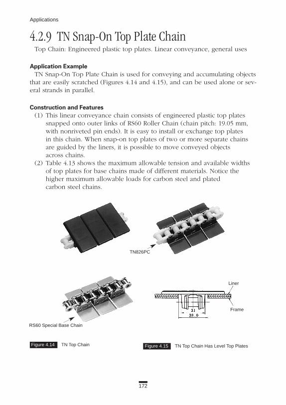
172
Applications
Figure 4.14 TN Top Chain Figure 4.15 TN Top Chain Has Level Top Plates
4.2.9 TN Snap-On Top Plate Chain Top Chain: Engineered plastic top plates. Linear conveyance, general uses
Application ExampleTN Snap-On Top Plate Chain is used for conveying and accumulating objects
that are easily scratched (Figures 4.14 and 4.15), and can be used alone or sev-eral strands in parallel.
Construction and Features(1) This linear conveyance chain consists of engineered plastic top plates
snapped onto outer links of RS60 Roller Chain (chain pitch: 19.05 mm, with nonriveted pin ends). It is easy to install or exchange top plates in this chain. When snap-on top plates of two or more separate chains are guided by the liners, it is possible to move conveyed objects across chains.
(2) Table 4.13 shows the maximum allowable tension and available widths of top plates for base chains made of different materials. Notice the higher maximum allowable loads for carbon steel and platedcarbon steel chains.
TN826PC
Liner
Frame
RS60 Special Base Chain

173
4. Top Chains
SprocketsUsually, standard sprockets for RS60 Roller Chain with 19 teeth (P.D. 115.74
mm) through 25 teeth (P.D. 151.99 mm) are used with this chain. Stainlesssteel and engineered plastic sprockets are also available.
Selection and Handling(1) Snap-on top plates will not separate from the base chain under normal
use. Excessive loads may cause snap-on top plates to separate. (2) An idler pulley should not be used for this chain.(3) The back portion of the top plate rises slightly above the level of the
conveying surface in the area where the chain engages with the sprocket. This should be considered when designing a system.
Chains for Special Applications(1) Lube-free LAMBDA® carbon steel or plated chains can be used for clean
applications. These chains are most effective if they are not exposed to water, liquid, or dust.
(2) MW top plates are low-friction and abrasion resistant.(3) TNU Snap-On Top Plate Chain series are used in curved movement.
Table 4.13 Maximum Allowable Loads for Top Plate Chains
Maximum Allowable Top Plate WidthChain Spec. Load (kN) 82.6 101.6 114.3 127 190.5 Carbon Steel 6.28
NP 6.28SS 1.03
Poly-Steel 0.88 N/A N/A N/A N/A
: Available

4.2.10 RS Plastic Top Chain Top Chain: Engineered plastic. General uses, food industries
Application ExampleRS Plastic Top Chain is used in electric, electronic, food (such as bakeries),
and other industries (Figure 4.16).
Construction and Features(1) Due to the small chain pitch, the transition area between conveyors is
minimal. This ensures smooth loading. (2) Double strand chain can be used in long conveyors due to increased
allowable load.(3) Table 4.14 shows chain sizes, availability, functions, and specifications.
SprocketsStandard sprockets will not work with double strand chains, RS60P-2 and
RS60PU-2 chain. Special sprockets must be used.
Table 4.14 RS Plastic Top Chain
MaximumChain Pitch Top Plate Allowable Low- Heat- Anti- PlasticNumber (mm) Width (mm) Load (kN) Standard Friction Resistant* Chemical Electroconductive Pin RS40P 12.70 20 0.44 N/ARS60P 19.05 30 0.88 N/ARS60P-2 19.05 60 1.27 N/A N/A N/A N/ARS60PU-2 19.05 60 1.08 N/A N/A N/A N/A
* Up to 140° C.
174
Applications
Figure 4.16 RS Plastic Top Chain
RS60P-2 (Top)
RS60PU-2 (Bottom)Curved Conveyor
: Available

175
4. Top Chains
4.2.11 Bel-Top Chain Top Chain: Engineered plastic belt-shaped chain. Bottling, canning,
and general uses
Application ExampleBel-Top Chain offers the power and reliability of a chain system with the
smooth operation of a belt. The chain is used for linear conveyance, accumu-lation, side loading, and movement of cans, bottles, or other materials that areeasily scratched (Figure 4.17).
Accumulation and movement with Bel-Top Chain is smoother than a systemwith several strands of Engineered Plastic Top Chains. In addition, the Bel-TopChain system, including guide rails and other parts, costs less.
Construction and Features(1) The chain consists of engineered plastic modular links with small pitch
(19.05 mm) and pins. It combines the functions of a chain and belt (Figure 4.18).
Figure 4.17 Bel-Top Chain Figure 4.18 Bel-Top Chain Combines the Features of Chains and Belts

176
Applications
(2) There are two types of Bel-Top Chain; MWB type has low-friction and anti-abrasion, KV-type has heat resistance (endures continuous temperatures of up to 250°C) and high-speed resistance. Each type uses different engineered plastic.
(3) Pins are made of engineered plastic in MWB-type and stainless steel in KV-type. There are specially shaped snap rings installed on both ends of the pin to prevent it from falling out.
Special features include the following:(1) Large conveying width (up to 3 m).(2) No slippage due to positive engagement with sprockets.(3) Easy to maintain. The chain consists of only three parts; therefore, it is
easy to assemble, connect, and disconnect. If a single link breaks, only the broken parts need to be replaced.
(4) Considering small chain pitch, small sprockets may be used to ensure smooth transfer between conveyors.
(5) Sprockets prevent tracking problems. This condition is difficult to prevent when using a conventional belt.
(6) It is easy to maintain a clean and sanitary operation. Therefore, the chain is widely used in the food industry.
SprocketsUse special engineered plastic sprockets with 10 teeth (P.D. 61.65 mm) for a
hexagonal steel shaft, or 24 teeth (P.D. 145.95 mm) with a square steel shaft.When 10-tooth sprockets are used, the area between conveyors can be mini-mized. On the other hand, 24-tooth sprockets offer smoother engagement withthe chain, and chordal action is reduced.
When conveying light products, the lateral distance between sprockets maybe extended. Refer to the manufacturer’s catalog for details.
Selection and Handling(1) Maximum allowable load of both MWB-type and KV-type is 1.96 kN for
1,524-mm-wide chain. However, this value is affected by temperature and speed. When the chain width is greater than 1,524 mm, check the manufacturer’s catalog for maximum allowable load.
(2) “Open type” of MWB-type has holes in the upper panel. These can be used in a variety of applications. For example, you can drain liquid or allow air flow through the chain during the operation.
(3) It is important to allow for catenary, and to install take-up on the return side. Special consideration needs to be given to the heat expansion of KV-type.

177
5. FREE FLOW CHAINS
Figure 5.1 Free Flow Conveyor Chains

178
Applications
5.1 WHAT IS FREE FLOW CHAIN? A free flow conveyor system allows you to stop conveyed objects (with a
stopper), while the chain (Figure 5.1) runs continuously underneath. After the stopper is released, conveying resumes (Figure 5.2).
It is possible to get free flow function even with standard RS (figure-eightside plates) roller chains by placing conveyed objects directly on the chains.However, during the accumulating mode, the chain will slide underneath,which may leave marks on the bottom of conveyed objects, and eventuallyleading to excessive wear.
Free flow chains were developed to eliminate the possibility of damagingconveyed objects during the accumulating mode. These chains are equippedwith rollers that support conveyed objects. When accumulating, freely rotatingrollers are in contact with the bottom side of goods conveyed, which ensuressmooth and damage-free operation.
There are several types of free flow chains. Figure 5.3 shows the relationamong various types of free flow chains.
Figure 5.3 Types of Free Flow Chains
Figure 5.2 Free Flow Conveyor System
Direction of Travel
Accumulation Transfer Accumulation Transfer
RS Roller Chain
Outboard Roller Chain
Duplex TopRoller Chain
Top Roller Chain
DOUBLE PLUS®
ChainNew Type
Available withAttachments
NarrowSpace
Chains to be two strands, located atboth sides of a conveyor. Stoppersand sorting devices may be installedbetween two chains.
Roller Table

179
5. Free Flow Chains
5.2 TYPES OF FREE FLOW CHAIN
5.2.1 DOUBLE PLUS® Chain Free flow conveyance: Light conveyance. Electric, electronic industries
Application ExampleDOUBLE PLUS Chain is a new type that meets low noise requirements and
high safety standards. It was invented in Japan in the 1980s, and it is nowbeing used around the world for electronics assembly lines as well as in theauto parts, beverage, and medical equipment industries.
The chain is widely used in electric or electronic industries on the assemblylines, where objects (for example, VCRs) are conveyed on pallets. Usually twochains are used as a set (Figure 5.4).
Pallets are usually made of aluminum with steel or plastic (polypropylene)liners at the chain-pallet contact point.
The common pallet type is: Size: 500 mm 3 500 mm.Weight: 20 to 30 kg (including the weight of conveyed objects).Pallet speed: 10 to 15 m/min.
Construction and FeaturesDOUBLE PLUS Chain has large center rollers with small rollers on both sides.
During conveyance, large center rollers and small rollers rotate at the samerpm. Chain tension, while conveying objects, is relatively low, as it is affectedprimarily by rolling friction.
Figure 5.4 DOUBLE PLUS® Chain
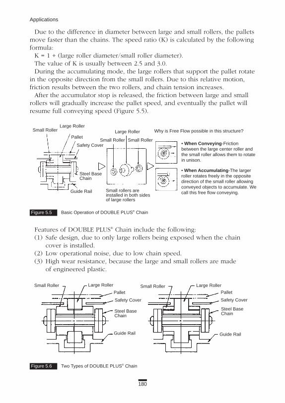
Due to the difference in diameter between large and small rollers, the palletsmove faster than the chains. The speed ratio (K) is calculated by the followingformula:
K = 1 + (large roller diameter/small roller diameter).The value of K is usually between 2.5 and 3.0.During the accumulating mode, the large rollers that support the pallet rotate
in the opposite direction from the small rollers. Due to this relative motion,friction results between the two rollers, and chain tension increases.
After the accumulator stop is released, the friction between large and smallrollers will gradually increase the pallet speed, and eventually the pallet willresume full conveying speed (Figure 5.5).
Features of DOUBLE PLUS® Chain include the following:(1) Safe design, due to only large rollers being exposed when the chain
cover is installed.(2) Low operational noise, due to low chain speed.(3) High wear resistance, because the large and small rollers are made
of engineered plastic.
180
Applications
Figure 5.5 Basic Operation of DOUBLE PLUS® Chain
Figure 5.6 Two Types of DOUBLE PLUS® Chain
Small Roller
Guide Rail
Guide Rail Guide Rail
Small Roller
Small Roller Small Roller
Small Roller
Large RollerLarge Roller
Large Roller Large Roller
Why is Free Flow possible in this structure?Pallet
Pallet Pallet
Safety Cover
Safety Cover Safety Cover
Steel BaseChain
Steel BaseChain
Steel BaseChain
Small rollers areinstalled in both sidesof large rollers
• When Conveying-Frictionbetween the large center roller andthe small roller allows them to rotatein unison.
• When Accumulating-The larger roller rotates freely in the oppositedirection of the small roller allowingconveyed objects to accumulate. Wecall this free flow conveying.

181
5. Free Flow Chains
There are two design types of DOUBLE PLUS® Chain. These are shown inFigure 5.6. In Figure 5.6 (left), the large roller is positioned between two smallrollers equipped with a step. The step portions of each small roller face eachother and are inserted in the ID of the large rollers, thus holding them in posi-tion. In the right-hand illustration, the large roller is equipped with steps onboth sides. The small roller is positioned over each step.
Although the designs are different, the performances are practically thesame. In Figure 5.6, the left-hand chain has a K speed ratio close to 3, whichis slightly higher than the other type.
In the design shown in Figure 5.6 (left) when the chain engages with thesprockets, the large rollers don’t lock; therefore, the pallets travel at the nor-mal conveying speed (three times the speed of chain) at the exit or entranceof the conveyor.
In the right-hand illustration, the large rollers lock when the chain engageswith the sprockets. Therefore, the pallet speed is reduced to the chain speedat the conveyor exit or entrance. This is convenient if you want to transfer apallet to another conveyor moving at a slower speed. If sprockets are loweredslightly, constant conveying speed at the exit from the conveyor is maintained.
The sizes of DOUBLE PLUS Chain are shown in Table 5.1.
Table 5.1 DOUBLE PLUS® Chain Sizes
Chain Chain Large Roller Small Roller AllowableNo. Pitch Diameter Width Diameter Width Load kN*
RF2030VRP 19.05 18.3 8.0 11.91 4.0 0.55
RF2040VRP 25.40 24.6 10.3 15.88 5.7 0.88
RF2050RFP 31.75 30.6 13.0 19.05 7.1 1.37
RF2060VRP 38.10 36.0 15.5 22.23 8.5 2.06
RF2080RFP 50.80 48.0 20.0 28.58 15.0 5.29
* Regular Type (A)

182
Applications
SprocketsUse special 10-tooth sprockets that engage with small rollers (Figure 5.7).
Selection and Handling(1) There are two types of DOUBLE PLUS® base chain: with or without
bushings. The bearing area on the type with bushings is larger, creating a contact surface between the pin and bushing. The bearing area on the type without bushings is limited to the contact surface between the side plate and the pin. Chain with bushings has much better wear characteristics.
(2) The guide rail and bottom surface of the pallet should be smooth and straight in a DOUBLE PLUS Chain system for proper operation. Therefore, check and compare that the chain has a flexible construction that can accommodate irregularities.
(3) Large and small rollers are available in different types of materials: standard, electroconductive, and high friction (for increased palletacceleration). These specifications may be combined to suit your needs.
(4) Aluminum extrusions are usually available through the manufacturer. If the weight on the pallets is very heavy, or you want to extend the working life of the system, steel rails should be used.
(5) If you lubricate between the pins and bushings to reduce the noise and wear elongation, do not allow oil to get on the contacting surface of the large rollers and small rollers or on the outer surface of small rollers. If these parts are contaminated with oil, the pallets will not accelerate fast enough or they won’t reach the operating speed because of roller slip. You should buy prelubricated chains.
(6) The rigidity of the chain depends on its structure. The greater the rigidity, the less likely that stick slip will occur (see Basics Section 2.3.5). If the conveyor is less than 15 m long, the possibility of stick slip is greatly reduced.
Specialized Sprocket
Figure 5.7 Specialized 10-Tooth Sprocket for Use with DOUBLE PLUS® Chain

(7) There will be a gap between head and tail sprockets of two separate DOUBLE PLUS® conveyors when they are positioned in one line. Install a pallet-supporting roller in the transition area (Figure 5.8).
Technical Trends(1) Small objects, such as screws, may fall between exposed chain compo-
nents, which can jam the system. Snap covers have been developed to prevent small objects from jamming the line (Figure 5.9).
(2) Besides chain, sprockets, and guide rails, many conveyor components, such as pallet guides (to control side-to-side motion) and brackets, have been designed for DOUBLE PLUS® Chain and guide rails. They are available as kits. Manufacturers are also expected to develop software packages to aid the conveyor designer in selecting the proper chains and components.
(3) There are DOUBLE PLUS® Chains with steel rollers for heavy loads.
183
5. Free Flow Chains
Figure 5.8 Placement of Pallet-Supporting Rollers
Conveying Surface
Conveying Surface
Pallet-Supporting Roller
Pallet-Supporting Roller
Sprocket
Sprocket
Direction of Travel
Direction of Travel
Figure 5.9 Snap Covers on DOUBLE PLUS® Chain
Snap Cover

184
Applications
5.2.2 Outboard Roller Chain—Side Roller TypeFree Flow Chain: Electric, electronic and precision machinery conveyance
Application ExampleOutboard Roller Chain with Side Rollers (Side Roller Chain) is used for free
flow conveyance, like DOUBLE PLUS® Chain, in the electric, electronic equip-ment, and auto parts industries. Usually two strands are used on the equip-ment (Figure 5.10). Please refer to DOUBLE PLUS Chain, in ApplicationsSection 5.1.1, for typical pallet size and weight guidelines.
Construction and FeaturesSide Roller Chain is based on standard roller chain with side rollers installed
on extended pins. There are three types of base chain:(1) RF-type (double pitch roller chain) with S-rollers (straight side plates,
small rollers).(2) RF-type (double pitch roller chain) with R-rollers (straight side plates,
oversized rollers).(3) RS-type (figure-eight side plates, small rollers; oversized rollers are
not available).
Figure 5.10 Outboard Roller Chain with Side Rollers
Conveyed Material
PalletChain
You can select various combinations of chain materials; carbon steel, platedcarbon steel, various stainless steel materials, and/or engineered plastic. Therelation between roller material availability and applicable chain sizes isshown in Table 5.2.
Small sprockets can be used with the RS-type to minimize conveyor height. Because the side roller diameter is larger than the chain pitch for the RS-

185
5. Free Flow Chains
type, side rollers cannot be installed on every pitch on the same side of the chain. They can be installed on every pitch in alternating positions (Figure 5.11).
In RF-type, the diameter and width of the side roller are different for S-rollers and R-rollers.
When the stopper in a free flow conveyor is released, pallets accelerate tothe chain speed. This acceleration is determined by the coefficient of frictionbetween the side roller and the pin. The smaller the coefficient of friction, thelonger it takes for the pallets to reach the speed of the chain. Faster accelera-tion can be accomplished by installing brake rollers. The construction andcoefficient of friction of the brake rollers are different for each chain manufac-turer. In engineered plastic side roller products from Tsubaki, the coefficientsof friction of chain are: with brake, 0.10; without brake, about 0.06.
Selection and HandlingOutboard Roller Chain has the following characteristics compared to
DOUBLE PLUS® Chain: (1) Greater allowable tension for the carbon steel chain (Table 5.3).(2) More economical. RF2050 chain costs about half as much, and sprockets
cost about two-thirds that of the equivalent size of DOUBLE PLUS Chain.(3) More noise. Comparing systems with the same pallet speed and sprock-
ets with the same number of teeth, Side Roller Chain emits about 10 to 15 dB(A) more noise than DOUBLE PLUS Chain.
(4) Because the body of Side Roller Chain is exposed over the guide rail, this chain does not have the same safety features as DOUBLE PLUS.
(5) Snap covers are not available for Side Roller Chain. It is difficult to prevent small objects from falling in between chain components.
(6) Complete kits for Outboard Roller Chain, including the guide rails and other components, are not available. Therefore, you have to create your own system.
Table 5.2 Outboard Roller Chain (Side Roller)
RS Attachment Type RF Double Pitch Type
Engineered Plastic Roller RS40~100 RF2040~RF2100
ElectroconductivePlastic Roller RS40~60 RF2040~RF2060
Steel Roller RS40~160 RF2040~RF2160
Table 5.3 Allowable Tension of DOUBLE PLUS® and Outboard Roller Chains
Chain Type Roller Type RF2040 RF2050 RF2060 RF2080
DOUBLE PLUS® Regular Series 0.88 1.37 2.06 5.29
Chain High Friction Series 0.44 0.69 1.03 2.65
Outboard Roller Steel Roller 2.65 4.31 6.27 10.7
Chain Plastic Roller 0.44 0.69 1.03 1.76
(Allowable load kN)

186
Applications
Figure 5.11 Installation of Side Rollers
SprocketsStandard sprockets may be used. In some cases, side rollers may interfere
with the sprocket hub. Additional machining of the hub might be required.
Selection and Handling(1) Although both R-rollers and S-rollers are commonly used in Side Roller
Chains, R-rollers should be considered if either of the following condi-tions exist: • The overall length of the machine is more than 10 m. • The chain speed is more than 20 m/min.
(2) R-rollers have lower coefficient of friction (without lubrication, R-roller: 0.12; S-roller: 0.21).
(3) Select Side Roller Chain according to the chain tension and allowable roller load. Make sure to consider the tension due to the accumulating mode when you calculate total chain tension.
(4) Side rollers can be installed in alternating positions, staggered or parallel. Staggered rollers tend to allow pallets to run smoother.
(5) Side Roller Chain requires lubrication to reduce wear elongation and to reduce noise level.
NOTE: Lubrication may affect (delay) acceleration; therefore, pleaseapply carefully.
Chains for Special ApplicationsSide Roller Chain is available in LAMBDA® construction for lube-free
operations.
Technical TrendsChain manufacturers are working on new chain designs that quiet
operation noise. Chain kits, including chain, guides, sprockets, and other components are
a focus of chain manufacturer development plans.Large pitch side roller conveyor chains are available to handle heavier loads.
Connecting Link
Staggered Installation Parallel Installation

187
5. Free Flow Chains
5.2.3 Outboard Roller Chain—Top Roller Type Free Flow Chain: Automotive industry, precision equipment industry,
general uses
Application ExampleOutboard Roller Chain with Top Rollers (Top Roller Chain) is used primarily
in the automotive and precision equipment industries for free flow conveyance(Figure 5.12).
Construction and FeaturesTop Roller Chain is based on the standard chain with extended side plates
(SK-1 attachments). Top rollers are installed on the pins that connect SK-1extended plates. Pallets with conveyed objects are loaded on the top rollers.Table 5.4 shows some of the base chains that are available.
Table 5.4 Outboard Roller Chain (Top Roller)
Base Chain Top Roller Spacing Top Roller Material Chain Pitch *Max. Allowable Load (kN)
RS Roller Chain Every Pitch, 2nd Pitch Steel, Plastic 12.7~31.75 2.65~17.1
Double Pitch Chain Every Pitch Steel, Plastic 25.4~63.5 2.65~17.1
Engineering Chain Every Pitch Steel 75~200 4.2~35
*Maximum allowable load listed in this table for RS Roller Chain and Double Pitch Chain is the same as that ofstandard carbon steel chains. For the Engineering Chain, it is one-seventh of the average tensile strength ofstandard chains.
Plastic Top Roller
Steel Top Roller
Regular Series
Figure 5.12 Outboard Roller Chain with Top Rollers

188
Applications
RS (single pitch) Top Roller Chain can only be equipped with an S-roller. R-rollers and S-rollers are available for RF (double pitch) Top Roller Chain.
The features of Top Roller Chain include the following points:(1) High maximum allowable tension.(2) Economical cost.(3) Lower stability than Side Roller Chain, because Top Roller Chain
is narrower.(4) Snap covers are not available for Top Roller Chain. It is difficult to
prevent small objects from falling in between chain components.(5) Noise levels during operation are higher than those for DOUBLE PLUS®
Chain. (Noise is about equal to Side Roller Chain.)(6) Top Roller Chain installation kits, including the guide rails and other
components, are not commonly available.
SprocketsStandard sprockets can be used with RS (single pitch) chain and with RF
(double pitch) chain with S-rollers. Other types of Top Roller Chain requirespecial sprockets.
Selection and HandlingTop Roller Chains are available with R-rollers and with S-rollers. The use of
R-rollers is preferred, especially if either of the following conditions exists: • The overall length of the equipment is more than 10 m. • The chain speed is more than 20 m/min. R-rollers have lower coefficient of friction (without lubrication,
R-roller: 0.12; S-roller: 0.21).
Chains for Special ApplicationsTop Roller Chains can be made of stainless steel, carbon steel, or plated
carbon steel.LAMBDA® Top Roller Chain is available for lube-free operations. Engineered
plastic top rollers should be used in this construction because they are lube-free.
Two types of Top Roller Chains have higher stability than standard TopRoller Chains (Figure 5.13). They are:
• TG-form with SK attachments that point downward.• Double Strand Top Roller Chain. Please refer to Plus α Alpha catalog for additional information.
Figure 5.13 Types of Higher Stability Top Roller Chain
Double Strand Top Roller
TR TG
Special Attachmentfor Prevention of Turnover

189
5. Free Flow Chains
5.2.4 Roller Table Chain (ST, RT) Free flow: Bottling, canning
Application Example Roller Table Chain lets you convey and accumulate groups of small, separate
objects, such as bottles, boxes, or cans. With Roller Table Chain, pallets areusually not used; the conveyed materials are placed directly on engineeredplastic rollers. (See Figure 5.14.)
Construction and FeaturesRoller Table Chain is constructed from two strands of chains, which are
connected with stay-pins and engineered plastic rollers that rotate freely.Conveyed objects are placed directly on the engineered plastic rollers.Conveyed goods are accumulated on the Roller Table Chain with low friction.
Figure 5.14 Roller Table Chain
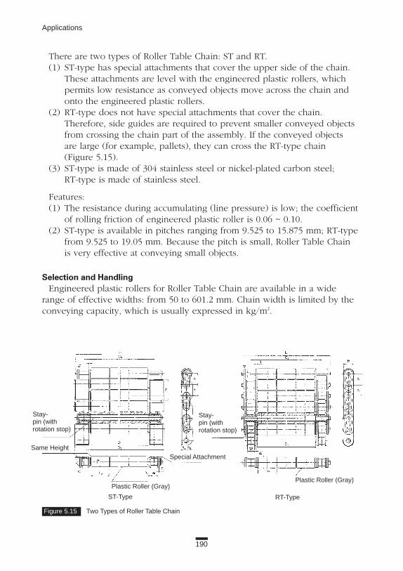
190
Applications
There are two types of Roller Table Chain: ST and RT.(1) ST-type has special attachments that cover the upper side of the chain.
These attachments are level with the engineered plastic rollers, which permits low resistance as conveyed objects move across the chain and onto the engineered plastic rollers.
(2) RT-type does not have special attachments that cover the chain. Therefore, side guides are required to prevent smaller conveyed objects from crossing the chain part of the assembly. If the conveyed objects are large (for example, pallets), they can cross the RT-type chain (Figure 5.15).
(3) ST-type is made of 304 stainless steel or nickel-plated carbon steel; RT-type is made of stainless steel.
Features:(1) The resistance during accumulating (line pressure) is low; the coefficient
of rolling friction of engineered plastic roller is 0.06 ~ 0.10.(2) ST-type is available in pitches ranging from 9.525 to 15.875 mm; RT-type
from 9.525 to 19.05 mm. Because the pitch is small, Roller Table Chain is very effective at conveying small objects.
Selection and HandlingEngineered plastic rollers for Roller Table Chain are available in a wide
range of effective widths: from 50 to 601.2 mm. Chain width is limited by theconveying capacity, which is usually expressed in kg/m2.
Figure 5.15 Two Types of Roller Table Chain
Stay-pin (with rotation stop)
Stay-pin (with rotation stop)
Same Height
Plastic Roller (Gray)Plastic Roller (Gray)
Special Attachment
ST-Type RT-Type
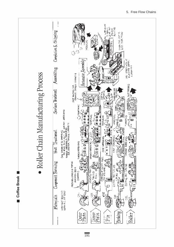
191
5. Free Flow Chains
Cof
fee
Bre
ak
•Ro
llerC
hain
Man
ufac
turin
gPr
oces
s

192
6. LARGE PITCH CONVEYOR CHAINS
Figure 6.1 Large Pitch Conveyor Chain

193
6. Large Pitch Conveyor Chains
6.1 WHAT IS LARGE PITCH CONVEYOR CHAIN?Large pitch conveyor chains (Figure 6.1) are big pitch chains with rollers,
originally based on cast iron chains. The base material was changed to steel,and they incorporated some of the features of drive chains and small pitchconveyor chains.
They were standardized by Tsubaki in the 1920s. They were developed inJapan as millimeter-unit pitch chains, available in a variety of pitches for agiven capacity. Similar chains are available in the United States, but are usuallymeasured in inch-unit pitch.
6.1.1 StandardsISO 1977/1 ~ 3 includes standards for large pitch conveyor chains. These
standards are for European-type chains, which have larger diameter bushings,pins, and rollers, and thinner, taller side plates than comparable sizes of chainsmade in the United States or in Japan.
Japan Chain Industry Association Standard JCAS 2-1982 governs seven cate-gories of large pitch conveyor chains. The major characteristics of these cate-gories are shown in Table 6.1.
RF 12 200 - RAverage tensile strength, in tons, of the chain when itwas originally designed
Chain pitch
Roller type
Table 6.1 Major Characteristics of Large Pitch Conveyor Chain
There are larger sizes than those shown in Table 6.1; in fact, tensile strengthcan exceed 4,460 kN! If you need extra-high performance chain, discuss theoptions with the manufacturer.
6.1.2 NomenclatureSome chain manufacturers use their own nomenclature. In the case of
Tsubaki, for example, chain size 16 with 200 mm pitch, is listed as RF12200-R.Here’s what that name means.
Chain Tensile Side Plate Inner Link Roller DiameterNumber Strength Pitch(Pin Dia.) (kN) (mm) Height Thickness Width Small Large
08 29.4 75;150 23 3.2 15.7 15.9 3211 68.6 75;150 33 4.7 20.7 22.2 4014 107.9 100;200 39 6.3 28.7 29.0 5016 176.5 150;300 46 8.0 35.8 34.9 6519 205.9 150;300 52 9.5 50.1 40.1 8022 274.6 200;450 66 9.5 55.9 44.5 10025 470.7 250;600 81 12.7 65.4 50.8 125

194
Applications
6.1.3 Construction and FeaturesThe structure of large pitch conveyor chain is shown in Basics Section 1.1.
6.1.3.1 Shape Features(1) Side plates are straight.(2) Because the radius of the side plate end is greater than half of
the side plate height, the corner of the engaging side plate will rise slightly when the chain joint engages the sprocket. This may cause interference with objects conveyed directly on a chain equipped with an S-roller. (The roller diameter is less than the height of the side plate.)
(3) The end of the pin (opposite to the head of the pin) is equipped with a cotter hole for a T-pin. This arrangement allows easy assembly or disassembly of chain links.
(4) The pin has a swell neck at one end, and the cotter side can either be double flat or have a D-shape. Accordingly, side plates have full round pin holes, and D-shaped or double-flat pin holes.
(5) There are three types of rollers available: R, F, and S (M, N).The F-roller is a feature of large pitch conveyor chains, since they are useful in guiding the chain on the rail. However, the flange wears against the rail, and therefore, should only be used when the chain is lubricated, or when the conveyed material acts as a lubricant. Additionally, F-rollers should be avoided where heavy loads are conveyed, otherwise the flange may wear quickly or break. As a rule, S-rollers are used to reduce sprockettooth wear due to smooth engagement with the sprocket, but are not suit-able for rolling conveyance.
(6) R- and F-rollers have small-diameter hubs on their sides.
6.1.3.2 Function Features(1) High rigidity.Large pitch conveyor chains are designed to carry heavy loads and endure
rough loading. Of course, there are limits to the chain’s integrity, and it isimportant to consult the manufacturer for details.
Let us check the chain’s resistance to bending. The following formula showsthe relationship between bending moment, M, and stress:
M = sZ = 1/6 3 s 3 H 3 t2
s: stress on side plateH: side plate heightt: side plate thickness
Using the equation, let’s compare the effects of side plate thickness (t) onchain rigidity when tensile strength, side plate height (H), pin diameter, andbushing diameter are held constant.

195
6. Large Pitch Conveyor Chains
Here are two examples. Case 1 reflects design considerations for a largepitch conveyor chain; Case 2 is for a small pitch conveyor chain.
Case 1.Bending moment: M1 = 1/6 3 s 3 H 3 t2
Case 2.t2 = t/2
s2 = 2s (in order to maintain the same tensile strength)M2 = 1/6 3 s2 3 H2 3 (t2)2 = 1/6 3 2s 3 H 3 (t/2)2
Bending moment: M2 = 1/12 3 s 3 H 3 t2
Therefore, the large pitch conveyor chain (Case 1) can withstand twice themoment (M) of small pitch conveyor chain (Case 2).
(2) Large pitch conveyor chain is designed to operate in harsh conditions. However, certain environments may affect the side plates, which can lead to stress-corrosion cracking, for example. This is a rare occurrence even for heat-treated side plates of this series.
(3) The chain is designed with relatively large clearances between components. Typically, even if foreign material gets between the chain parts, the rollers will continue rotating, and articulation of the links is not easily impaired.
(4) In Table 6.2, different materials are listed for each chain part of frequently used series. This lets you create a chain specifically for your operating environment at an economical cost. In Table 6.2, the “O” markdesignates available materials for the chain parts. Table 6.3 shows the relation of materials and the chain parts.
(5) Attachments have high strength. Take the commonly used A attachment as an example. During operation, it is subjected to bending and twisting forces. Bending moment and twisting moment are calculated according to formulas shown below.
Bending moment (M) = 1/6 3 s 3 H 3 t2
Twisting moment (T) = A 3 t 3 N 3 t2
The allowable values of M and T are quite high for large pitch conveyorchain compared with small pitch conveyor chains. Attachments have higherresistance to breakage during operation, but verify the bending and twistingmoments. Manufacturers can help you determine the appropriate chain sizeand attachment for an application.

: Available : Not Typically Used
196
Applications
(6) It is relatively easy for users to modify chain attachments, by machining or welding, to fit specific applications. Consult with the chain manufac-turer in advance to avoid damaging the chain.
6.1.3.3 Disadvantages(1) Larger pitch chain increases the size of the equipment, which may be
considered an obstacle.(2) To keep the size of the equipment small when using large pitch chain,
sprockets with small numbers of teeth are commonly used. This contributes to greater speed variation of the chain.
(3) Although applications can run as fast as 330 m/min., normally large pitch chains should be used at low speeds.
Large pitch conveyor chains are generally more costly than smaller pitch roller chains, and in the case that the system or the chain does not function as designed, it may be more difficult to resolve these issues than with smaller chains.
You are ultimately responsible for selecting the proper chain, so follow all the steps in the selection process, and consider what effects the system or the conveyed materials have on the chain, in strength, wear, corrosion, etc. As stipulated in previous sections of this book, the calculations of bending andtwisting strength of chain attachments, large or small, are the same as withother machine elements.
Work with a chain manufacturer who has a good reputation for quality andsafety; who offers knowledge, expertise, and superior service; and who manufac-tures quality product. Remember, not all chains and attachments are listed in thecatalog, as it would be impractical to publish all specifications and information.
Table 6.2 Typical Material of Commonly Used Chain Series
Non-Heat-Treated 400 Series 304
Steel Heat-Treated Steel Stainless Steel Stainless Steel Cast Iron
Side PlatePinBushingRoller

DT
GT
ApplicationGreater
Function Features
Basic Series • Most Popular andEconomical
• Greater Wear Life BetweenBushing and Roller
• Compact Design• Popular Series
• Greater Wear Life BetweenPin and Bushing
• For Cement Conveyor• For Bulk Conveyor
• Good For Directly Conveyingon the Chain
• For Compact Design(Power and Space Saving)
• For Unit Conveyor
• For High Accuracy• Positioning with Indexing
Drive on Unit Conveyor
• Low Noise, Clean, andLight Weight
• No-Lube
• Corrosion Resistance,Heat Resistance, and ColdResistance
• Corrosion Resistance,Heat Resistance, and ColdResistance
• Incidental Water Contact
• Incidental Water Contact• Good For Conveying
Abrasive Bulk Materials
• Clean, Low Noise, CorrosionResistance
• Light Weight
• No-Lube
Wear ResistanceBetween Bushingand Roller
Reinforced Series
Wear ResistanceBetween Pin andBushing
Reinforced Series
Bearing Roller Series
Bearing Bush Series
Plastic Roller Series
Plastic Roller andPlastic Sleeve Series
400 Stainless SteelSeries
Reinforced 400Stainless SteelSeries
300 Stainless SteelSeries
Corrosion and WearResistance BetweenPin and Bushing
Corrosion and WearResistance BetweenPin, Bushing, andRoller
Reinforced Series
300 Stainless SteelSeries Plastic RollerSeries
300 Stainless SteelSeries and PlasticSleeve Series
For Regular
No
rmal
Env
iro
nm
ent
Co
rro
sive
and
Hig
h-T
emp
erat
ure
Env
iro
nm
ent
Lig
ht
Co
rro
sive
Env
iro
nm
ent
For WearResistance
For Heavy-WeightObjects
For High-AccuracyPositioning
For Low Noise andNo-Lube
For CorrosionResistance and HeatResistance
For Partial CorrosionResistance
For Low Noise andNo-Lube
AT
CT
BT
B-DT, B-AT
RFN
DTP
RFS-DTP
NT
PT
ST
MT
RT
YT
STP
RFS-STP
NOTE: 400 Stainless Steel Series Chain May Rust Depending on Environmental Conditions
197
6. Large Pitch Conveyor Chains
Table 6.3 Relationship of Materials and Components

198
Applications
6.2 STANDARD CONVEYOR CHAINS
6.2.1 RF Conveyor Chain Large conveyance: Basic type, general uses
Application ExampleThis is the basic chain series of large pitch conveyor chains (Figure 6.2).
Construction and FeaturesSee Basics Section 1.1.
SprocketsStandard sprockets with 6, 8, 10, and 12 teeth are available for RF Conveyor
Chains with R-rollers. For S-rollers, sprockets with 15 and 25 teeth (7.5 and12.5 effective teeth, respectively) are also available.
Figure 6.2 Large Pitch Conveyor Chain
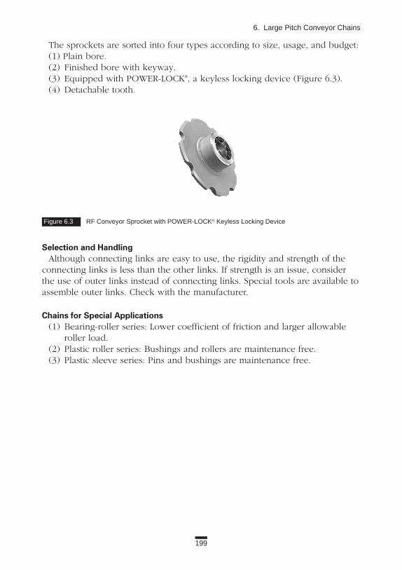
199
6. Large Pitch Conveyor Chains
The sprockets are sorted into four types according to size, usage, and budget:(1) Plain bore. (2) Finished bore with keyway.(3) Equipped with POWER-LOCK®, a keyless locking device (Figure 6.3).(4) Detachable tooth.
Selection and HandlingAlthough connecting links are easy to use, the rigidity and strength of the
connecting links is less than the other links. If strength is an issue, considerthe use of outer links instead of connecting links. Special tools are available toassemble outer links. Check with the manufacturer.
Chains for Special Applications(1) Bearing-roller series: Lower coefficient of friction and larger allowable
roller load.(2) Plastic roller series: Bushings and rollers are maintenance free.(3) Plastic sleeve series: Pins and bushings are maintenance free.
Figure 6.3 RF Conveyor Sprocket with POWER-LOCK® Keyless Locking Device

200
Applications
6.2.2 RF Bearing Roller Conveyor Chain Large conveyance: High performance chain. General uses
Application ExampleRF Bearing Roller Conveyor Chain is used in automobile, steel, electric, and
other industries.
Construction and FeaturesIn this large conveyor chain, cylindrical roller bearings are installed between
the bushing and roller of the RF Conveyor Chain (Figures 6.4 and 6.5).Compared to basic RF Conveyor Chain, RF Bearing Roller Conveyor Chain
has the following features:(1) The coefficient of rolling friction for RF Bearing Roller Conveyor Chain
is one-third to one-sixth that for RF Conveyor Chain. Basic RF Conveyor Chain: without lubrication, 0.13 to 0.18; with lubrication, 0.08 to 0.12. RF Bearing Roller Conveyor Chain: 0.03. This means the chain tension is reduced, and, frequently, a smaller chain size can be used. The conveyor will also require less energy to operate, making it more economical.
(2) The initial cost of equipment is reduced. Because the coefficient of rolling friction is lower, you can use smaller sprockets, motors, reducers, shafts, bearings, and frames.
Figure 6.4 RF Bearing Roller Conveyor Chain
Figure 6.5 RF Bearing Roller Conveyor ChainIncludes Cylindrical Roller Bearings
Bushing
Spacer
Cylindrical Roller Bearing
Roller

201
6. Large Pitch Conveyor Chains
(3) The allowable load of the roller is increased. The allowable roller loadfor RF12000-R Bearing Roller Conveyor Chain is 8.35 kN, which is 1.6 to3.3 times greater than the equivalent size of a basic type with lubrication(2.50 kN for nonheat-treated roller; 4.17 kN for heat-treated roller).Capacity of the roller for RF12000-R Bearing Roller Conveyor Chain isequivalent to RF26200-R Conveyor Chain with heat-treated rollers. This istwo sizes larger. In horizontal and slightly inclined conveying, usually thechain size is determined by the allowable load of the roller. Because ofthe reasons we have discussed, you can select a chain two to three sizessmaller. Rollers are also exposed to high load when they engage withsprockets. Even though this load may be several times greater than thevertical load on rollers during conveying, it is within the capacity rangeof bearing rollers.
(4) Lower maintenance. RF Bearing Roller Conveyor Chain has grease pockets on both its sides. Although we have received reports that thesechains have been operated for five years without any maintenance, wesuggest that you lubricate the bearing roller occasionally.
(5) Longevity of the bearing roller. The bearing roller is large in diameterand short in length; therefore, failure due to foreign material gettinginside it is rare. Some types of roller bearings are prone to failure due to foreign objects causing misalignment.
(6) Accepting thrust load. A self-lubricating spacer is installed on both sidesof the roller to accept thrust load. The spacer prevents a direct contactbetween the rotating roller and the side plate; therefore, wear particlesgetting inside the bearing is minimized.
(7) Stick-slip resistance. Stick slip is virtually eliminated because of the lowcoefficient of friction in a wide range of speeds. Consult the manufactur-er when conveyor speed is less than 2 m/min.
(8) Wide range of chain sizes is available. The ball bearings commonly avail-able on the market cannot be adapted for the needs of chains due totheir limited load capacity. It is difficult to adapt ball bearings to rollerswith diameters less than 45 mm, but roller bearings can be adapted foruse by using the bushing and roller as bearing races.
202
Applications
SprocketsThe standard sprockets used for RF Conveyor Chain are used for RF Bearing
Roller Conveyor Chain.
Selection and Handling(1) The design of standard bearing-roller spacers is similar to spacers used
in ordinary ball bearings. They are not water- and dust-proof. Oil- orlabyrinth-seals can be installed (on a made-to-order basis) if the chain is going to be exposed to water or dust. Please consult the chain manufacturer.
(2) A grease nipple can be installed on the pin head to provide grease tobearing parts (only certain sizes are available).
(3) The working temperature is limited to -20° to 80°C. The limiting factor isthe spacer. When a temperature-resistant material is used for the spacer,operating temperatures may be expanded. Contact the manufacturer foradditional information.
(4) To reduce the impact of the bearing roller as it engages the sprocket, usesprockets with greater numbers of teeth. For example, if the chain speedis 30 m/min., use a 10-tooth sprocket. Consult with the manufacturer ifthe chain speed is greater than 30 m/min.
(5) Do not select Bearing Roller Chain based on roller allowable load alone.In some applications, you also need to verify the strength of attachmentsto prevent breakage. Refer to the manufacturer’s catalog for additionalinformation.
Chains for Special Applications(1) Outboard Bearing Roller Conveyor Chain is used on assembly lines
(Figure 6.6). In this type of chain, bearing rollers are installed on the outside of the chain, making it ideal on long assembly lines, like auto lines, where work is performed on the conveyed products along the line. Outboard Bearing Roller Conveyor Chain is easy to support on the return side. If you combine the design features of Outboard Bearing Roller Conveyor Chain and Bearing Bush Chain, you can create a chain with very, very low elongation (practically nonexistent) and minimal rolling friction.
(2) Waterproof-bearing Roller Conveyor Chain (Figure 6.7) has heat-treated bearings made of 403 stainless steel, and includes oil-seals and grease nipples. Originally this chain was developed for the “shower test,” which checks the leakage in automobile manufacturing. It can be used in any application where the chain is exposed to water spray.
NOTE: Charge with grease regularly.

203
6. Large Pitch Conveyor Chains
(3) Plastic sleeve type. Installation of plastic sleeves between the pins and bushings makes Bearing Roller Chain maintenance free. It also reduces the allowable tension. It is available in the following sizes: RF03, RF05, RF450, and RF10.
(4) A variety of attachments, including special attachments, can be installed on RF Bearing Roller Conveyor Chain.
Technical TrendsBecause of the lower initial cost of the entire installation, RF Bearing Roller
Conveyor Chain has gained acceptance in a wide range of applications. Furtherseries development is required to respond to various applications.
Figure 6.6 Outboard Bearing Roller Conveyor Chain
Figure 6.7 Waterproof-bearing RollerConveyor Chain
Outboard Bearing Roller
Guide Rail Sprocket
Grease Nipple
Spacer
Cylindrical Roller Bearing
Oil Seal
Roller
S-Roller

204
Applications
6.2.3 RF Plastic Roller Plus Plastic Sleeve Conveyor Chain
Large Pitch Conveyor Chain: Maintenance-free type for light load
Application ExampleRF Plastic Roller Plus Plastic Sleeve Conveyor Chain is ideal for maintenance-
free, light-load applications. It is not suitable for conveying bulk materials(such as grains) or when the application exposes it to rough handling (Figure 6.8).
Construction and FeaturesSee the section on Plastic Sleeve Chain in Small Pitch Conveyor Chains
(Figure 6.9).
SprocketsStandard RF Conveyor Chain sprockets may be used.
Selection and HandlingThe maximum allowable load of this chain is smaller than the standard
series. For example, maximum allowable load of RF05100-R with plastic sleeveis 5.20 kN (with 8-tooth sprocket), while for the standard type it is 9.80 kN.This represents 47 percent reduction in the maximum allowable load. Thecoefficient of rolling friction is also 47 percent lower (0.08 versus 0.15 for stan-dard type without lubrication). Therefore, it is important to note that while themaximum allowable chain tension is reduced, the coefficient of friction is alsoreduced commensurately. The result is that the allowable conveyed objectweight on the conveyor remains the same.
Figure 6.8 RF Plastic Roller Plus Plastic Sleeve Conveyor Chain
Figure 6.9 Wear Comparison
Cha
inW
ear
Elo
ngat
ion
Operation Time without Lubrication
Carbon Steel Chain
Plastic Sleeve Chain
Engineered Plastic Roller
Engineered Plastic Sleeve

205
6. Large Pitch Conveyor Chains
6.3 SPECIALTY CONVEYOR CHAINS
6.3.1 Bucket Elevator Chain Large conveyance: Vertical conveyance of grain and other bulk materials for
the cement, chemical, and food industries
Application ExampleBucket Elevator Chains convey bulk materials vertically. You might see this
type of chain used to move cement, coal, or grain, for example. Buckets areinstalled at regular intervals, and the chain moves continuously, scooping andconveying the product. Because they are effective and economical, BucketElevator Chains are widely used (Figure 6.10).
When the chain engages the upper sprocket, the buckets are tipped, andconveyed objects are discharged. Discharging occurs either with centrifugalforce or continuously, which uses the bottom side of the bucket as a guide for the next bucket.
The trend has been for bucket elevator equipment to become smaller, toeconomize on installation costs. To reduce the operating costs, the chain musttravel faster (more than 80 m/min.). Therefore, the centrifugal discharge buck-et elevator has become more common (Figure 6.11). Usually, the capacity ofthe conveyed material is within the range of 300 ton/h.
Figure 6.10 Bucket Elevator Figure 6.11 Discharging of Buckets Occurs with Centrifugal Force or Continuously
ContinuousDischarge
CentrifugalDischarge
206
Applications
In large-bucket elevators, two chains are installed, one on each side of thebucket. Small-bucket elevators use only one strand of chain. The two-strandarrangement is a preferable design, ensuring safer operation.
Construction and FeaturesBucket Elevator Chain is based on standard large pitch conveyor chain with
K-2 or G-4 attachments. Buckets are spaced evenly (usually every two links)over the length of chain.
Three important construction features include the following:(1) Superior wear resistance of pins and bushings, which reduces chain
elongation. This has become increasingly important as cement makershave increased the amount of slag in concrete.
(2) High fatigue resistance.(3) Easy connecting and disconnecting. This is very important because of
the limited space in the elevator housing. Chain must be easy to handle.
SprocketsUsually, sprockets with 12 teeth are used in low-speed bucket elevators
(chain speed less than 45 m/min.). High-speed bucket elevators normallyrequire 24-tooth sprockets. It is important to choose a sprocket with suitablepitch-line clearance.
Excess conveyed material may accumulate in the bottom of the casing,which can cause accelerated wear. Worn chain and sprockets will not engagecorrectly; the sprockets may have to be replaced. Sometimes, welding materialonto the tooth at the point of excessive wear will restore the sprocket, but it isnot recommended. Additionally, this procedure is extremely difficult with thesprocket that is located at the top of the bucket elevator.
Even sprockets with hardened teeth are subject to excessive wear in bucketelevators, due to the abrasive nature of conveyed materials. For example, incement conveyors, there is a point of sprocket hardness at which wear is virtu-ally eliminated. However, it is impractical and expensive to make such hardteeth in standard sprockets. In the 1980s, detachable-tooth sprockets weredeveloped, which permit the replacement of the tooth part only (Figure 6.12).The body of the sprocket remains on the shaft, which reduces repair time andcosts. By using special materials in the tooth insert, high tooth hardness isachievable, and therefore, wear life is increased. Use of detachable-toothsprockets is increasing, especially in the cement industry.

207
6. Large Pitch Conveyor Chains
Selection and Handling(1) Choose Bucket Elevator Chain carefully. If the chain breaks, it is
extremely difficult and time consuming to remove broken chain from thebottom of the casing. Re-installation is also very demanding. Rely onchain from manufacturers with proven records for quality and reliability.
(2) Use special tools to connect and disconnect chain links.(3) Avoid grinding the pins, heating the plates, or increasing the size of side
plate holes during chain assembly. These procedures, sometimes used atfacilities, allow easier assembly of links; however, it compromises thestrength of chain, which can lead to ultimate failure.
(4) Consider using detachable-tooth sprockets.(5) For safety reasons, inspect chain and sprockets frequently, since chains
and sprockets have a limited useful life.
Figure 6.12 Detachable-Tooth Sprocket
SprocketBody
Nut Tooth InsertBolt

208
Applications
6.3.2 Flow Conveyor Chain Large conveyance: Conveyance of bulk materials in a closed case; cement,
chemical, and food industries
Application ExampleFlow Conveyor Chain moves bulk materials in a closed case. It conveys
the particles horizontally, on a slight incline, or vertically in an arrangementshaped like the letter L. This conveyor is sometimes called a Redler Conveyor(Figure 6.13).
Generally, a flow conveyor is used widely in the conveyance of bulk materi-als such as cement and fertilizer in chemical industries, and grain in foodindustries. Because it is enclosed, dust from the conveyed materials is con-tained, and will not pollute the surrounding area. A flow conveyor is not usu-ally used to move sticky, dusty, or low-density products.
A flow conveyor set up to move cement has an average capacity of 300ton/h and a speed of 35 m/min. Usually one strand of chain is used.
Construction and FeaturesSpecially shaped attachments with large clearances (Figure 6.13) are installed
on small pitch or large pitch conveyor chains. The chain operates in a casingfilled with conveyed material, such as grain, flour, or ash.
Figure 6.13 Flow Conveyor Chain

209
6. Large Pitch Conveyor Chains
This is based on a phenomenon used in a basic science experiment; whenyou put sand in a long cylinder, closed at one end with paper, and push thesand with all your strength, the paper cannot be broken if the cylinder is longenough. This is because the friction between the sand and the cylinderabsorbs all of the pushing force. Conversely, in the flow conveyor, the attach-ments work as moving walls, and the sand moves along with it. To lift con-veyed objects, the friction at the bottom wall of the conveyor must support theweight of the vertical portion, therefore, the conveyor must have a bottom line“L” shape.
Because there is very little relative movement among the conveyed materialsin this application, breakage is rare. The case width is determined by theattachment dimensions; usually it is less than 750 mm.
Chains for flow conveyors include: RF03075 (average tensile strength, 29 kN)through RF26200 (314 kN) for grain conveyance; RF450W (108 kN) throughRF36300N (868 kN) for other applications.
SprocketsStandard sprockets for RF-type conveyor chain are used for flow conveyors.
Detachable tooth sprockets are beginning to be used these days.
Selection and Handling(1) There are several types of attachments available, depending on design
and arrangement of the conveyor and whether material is pushed against the bottom of the casing or its side walls.
Figure 6.14 shows several types of attachments (L, B, U2V, and W). The set-up on the right-hand side has more pushing power than the one on the left-hand side. The specific properties of the material conveyed determine the type of attachments that should be used. Discuss your application with the manufacturer.
Figure 6.14 Examples of Attachments for Flow Conveyor Chain
L B U2V W

Figure 6.15 Installation of a Cleaner on a Flow Conveyor Chain
Figure 6.16 NFX-Type Block Chain
Direction
Cleaner
Sweeping Board
210
Applications
(2) KL-type attachment is an inclined version of an L attachment. This attach-ment can convey low-density and sticky materials.
(3) In grain applications, installation of a cleaner prevents mixing of differ-ent types of grains, and the cleaner removes any particles in the casingthat could go bad. Usually the cleaner is installed at intervals of 6 m(Figure 6.15).
(4) An M-roller, which rotates more smoothly than an S-roller, is typicallyused in the base chain.
(5) If the conveyed materials are highly abrasive materials, special blockchain provides longer wear life. (Figure 6.16 shows a set-up with NFX-type block chain.)
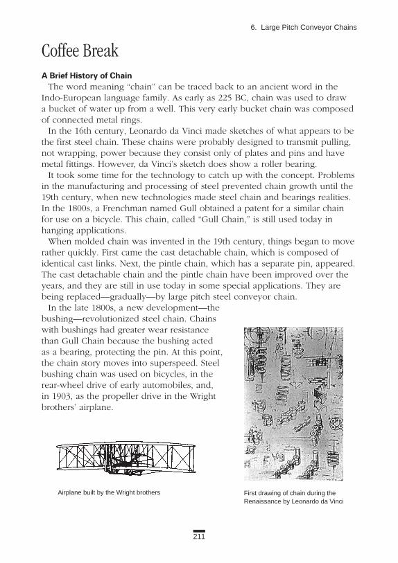
211
6. Large Pitch Conveyor Chains
Coffee Break A Brief History of Chain
The word meaning “chain” can be traced back to an ancient word in theIndo-European language family. As early as 225 BC, chain was used to draw a bucket of water up from a well. This very early bucket chain was composedof connected metal rings.
In the 16th century, Leonardo da Vinci made sketches of what appears to bethe first steel chain. These chains were probably designed to transmit pulling,not wrapping, power because they consist only of plates and pins and havemetal fittings. However, da Vinci’s sketch does show a roller bearing.
It took some time for the technology to catch up with the concept. Problemsin the manufacturing and processing of steel prevented chain growth until the19th century, when new technologies made steel chain and bearings realities.In the 1800s, a Frenchman named Gull obtained a patent for a similar chain for use on a bicycle. This chain, called “Gull Chain,” is still used today in hanging applications.
When molded chain was invented in the 19th century, things began to moverather quickly. First came the cast detachable chain, which is composed ofidentical cast links. Next, the pintle chain, which has a separate pin, appeared.The cast detachable chain and the pintle chain have been improved over theyears, and they are still in use today in some special applications. They arebeing replaced—gradually—by large pitch steel conveyor chain.
In the late 1800s, a new development—thebushing—revolutionized steel chain. Chainswith bushings had greater wear resistancethan Gull Chain because the bushing acted as a bearing, protecting the pin. At this point,the chain story moves into superspeed. Steelbushing chain was used on bicycles, in therear-wheel drive of early automobiles, and, in 1903, as the propeller drive in the Wrightbrothers’ airplane.
Airplane built by the Wright brothers First drawing of chain during the Renaissance by Leonardo da Vinci

212
Applications
6.3.3 Parking Tower ChainLarge conveyance
Application ExampleShortage of parking in large cities created a demand for carousel-type (verti-
cal-rotation) multilevel parking, that first appeared in Japan in 1962 (Figure6.17). Tower parking lots permit the storage of many vehicles (usually morethan 30 cars) in a small space. Over the years, tower parking has becomeincreasingly popular. Currently there are more than 10,000 of them in Japan.
Parking Tower Chain supports and rotates the cage containing the vehicle.As an interesting note: Elevator parking garages, which use transmission rollerchains or wire ropes to raise and lower the vehicles, are increasing in number.But vertical-rotation garages are still the majority.
Construction and FeaturesThere are only a few manufacturers producing parking tower systems.
However, each manufacturer produces a specific design. Figure 6.18 shows an example of Parking Tower Chain.The entire assembly consists of chain, attachments, and side rollers. The
chain receives tension, which can be summarized as follows:Chain tension = weight of automobiles and cages + weight of the chain
+ friction on the side roller + tension from take-up.
Figure 6.17 Vertical Rotation Parking Elevator Figure 6.18 Example of Parking Tower Chain

213
6. Large Pitch Conveyor Chains
Each attachment must support the weight of an automobile and a cage. Theside rollers prevent the attachments from tilting. Spacing of each cage isbetween 1,600 and 2,000 mm, and attachments are installed on every fourthchain link. Therefore, the chain pitch is 400 to 500 mm. Tensile strength variesbetween 1,333 and 1,500 kN, depending on the type of chain that is used (thelargest one is 2,940 kN). Standard chain speed is 16 m/min., but in someapplications speeds reach 25 m/min.
SprocketsThe special shape sprocket with 12 teeth is used with this chain. Usually the
sprocket is made by the original equipment manufacturer.
Selection and Handling(1) Safety is a major concern with this application. The technical standards
developed by the Japan Parking Industry Association require a safety factor of more than seven.
(2) It is very important that the original equipment manufacturer (OEM) andthe chain manufacturer work closely to select the design and size of thechain for the application. Only manufacturers with experience in thistype of application should be considered.
(3) Make sure to include the weight of the chain itself in calculations. It is an important factor, since the number of cars that can be stored may beaffected by the weight of the chain.
(4) Pins, bushings, and side rollers must be lubricated regularly, and all com-ponents must be inspected frequently. These should be included in themaintenance contract from the OEM.
Technical TrendsDesirable characteristics for Parking Tower Chain include low noise, high-
speed stability, light weight, and maintenance free.
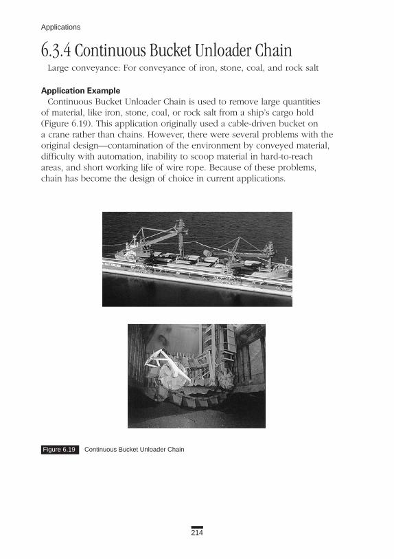
214
Applications
6.3.4 Continuous Bucket Unloader Chain Large conveyance: For conveyance of iron, stone, coal, and rock salt
Application ExampleContinuous Bucket Unloader Chain is used to remove large quantities
of material, like iron, stone, coal, or rock salt from a ship’s cargo hold (Figure 6.19). This application originally used a cable-driven bucket on a crane rather than chains. However, there were several problems with the original design—contamination of the environment by conveyed material, difficulty with automation, inability to scoop material in hard-to-reach areas, and short working life of wire rope. Because of these problems, chain has become the design of choice in current applications.
Figure 6.19 Continuous Bucket Unloader Chain

215
6. Large Pitch Conveyor Chains
In this conveyor form, buckets that scoop conveyed objects are installedbetween two chains. Mobility and flexibility make this equipment differentfrom the conventional bucket elevator. The conveyor system can be moved todifferent locations, and the equipment can be transformed from an L-shape toan I-shape to get to hard-to-reach areas.
The maximum conveyance capacity: 3,000 ton/h.The maximum chain speed: about 100 m/min.Some types of flow conveyors are used for unloaders.
Construction and FeaturesChains used in continuous bucket unloaders are exceptionally large,
even when compared to other large pitch conveyor chains. Average tensilestrengths are 3,040 kN, 3,630 kN, and 4,460 kN for some of the heaviestchains. Usually N-rollers are used in the chain.
SprocketsThe sprockets are exposed to high speeds, heavy shock loads, and corrosive
and abrasive materials. Special sprockets with more than 12 teeth and with anoise-reduction factor should be used. Wear-resistant, detachable-tooth sprock-ets are frequently used.
Selection and Handling(1) The chain must have exceptional wear resistance because it is exposed
to high speeds, heavy shock loads, and conveyed materials that are corrosive and abrasive. For example, in the case of coal, the corrosive-ness varies with each coal mine.
(2) Chain attachments should have high strength to support large bucket loads.(3) Noise and abrasion of sprockets are important considerations.(4) Choose chain from a manufacturer with a lot of experience and known
to produce a high-quality product. Select the chain only after communi-cating application requirements to the manufacturer.
(5) Assembly of large pitch conveyor chain on the equipment can be anenormous task. There are special tools available that can assist in con-necting the chain.
Technical TrendsManufacturers are working to develop relatively light-weight chain for the
load it carries, and sprockets that can provide long-term performance with lownoise levels.

216
Applications
6.3.5 Large Bulk Handling Conveyor Chain (CT) Large conveyance: The steel industry, container conveyance
Application ExampleLarge Bulk Handling Conveyor Chain (CT) is used in the steel industry to
convey hot steel coils (up to 700°C) as well as slabs or other heavy objects,such as containers. This chain is very strong. It can convey several coils, whichcan weigh up to 45 ton/coil.
Construction and FeaturesCT Chain is used in pairs, and heavy objects are conveyed directly on them.
Standard large pitch chains do not have enough capacity to support theextremely heavy loads (the limiting factor is the roller). For that reason, specialcylindrical bearing rollers have been developed. They combine a high allow-able load for the roller with low coefficient of friction. The coefficient of fric-tion is 0.03, which is one-third to one-fourth the coefficient of friction of standard large pitch conveyor chain in normal temperatures.
Figure 6.20 and Table 6.4 show the structure, dimensions, and functions ofthis chain.
A coil can be conveyed on its side or straight up. When the coil is on itsside, you can use the chain as shown in Figure 6.20. Special attachments needto be used when conveying a coil straight up. Figure 6.21 shows examples ofLarge Bulk Handling Conveyor Chains with attachments for conveying roundobjects, and one for curved conveyance.
Figure 6.20 Large Bulk Handling Conveyor Chain (CT)
Grease Nipple

Roller Link Plate Max. Allowable Max AllowableChain No. Pitch (mm) Dia. (R) Height (H) Roller Load (kN) Load (kN)
CT 60 300 400 500 125 171 29.4 83.3CT 90 300 400 500 135 182.5 35.3 126CT 130 300 400 500 150 195 42.2 181CT 160 400 500 600 175 227 55.9 224
217
6. Large Pitch Conveyor Chains
SprocketsLarge Bulk Handling Conveyor Chain requires special sprockets. They must
operate at low speeds (less than 15 m/min.) and usually have six to eightteeth, which keeps the diameter small, and cost down.
Technical TrendsThe coils are sometimes very hot, and are frequently transported through a
heat chamber. For these applications, the chain must be heat-resistant. In onespecific case, steel slabs were placed directly on the chain in five piles. Eachpile weighed 80 ton, and the surrounding temperature was 900°C. In extremesituations like this, consult the manufacturer.
Figure 6.21 Large Bulk Handling Conveyor Chain (CT) with Special Attachments
Table 6.4 Dimensions and Functions of Large Bulk Handling Conveyor Chain (CT)

218
Applications
6.3.6 Block Chain (Bar and Pin) Large conveyance: The steel industry, conveyance of sand and earth, shuttle
traction
Application ExampleBlock Chain is used for cooling high-temperature steel bars, seamless pipes,
or for pushing red-hot slabs and billets, for example (Figure 6.22). In additionto the steel industry, Block Chain is used for vertical conveyance of sand andearth, and for shuttle traction.
Construction and FeaturesThis chain is usually composed of three parts: two outer plates and one (or
sometimes two) inner plate (block) that are connected with pins. The tensilestrength ranges from 309 to 2,720 kN.
In comparison to roller chain, Block Chain has the following features:(1) Greater impact resistance due to the strong construction and high rigidity.(2) Higher strength considering chain weight.(3) All the main parts are heat-treated for greater wear resistance against the
guide rails.(4) Usually the bottom side of the plate slides on the guide rail; the chain
does not have rollers. It’s possible to push and carry conveyed objectson the guide rails using special pushers (dogs) attached to the chain(Figure 6.23).
Figure 6.22 Block Chain
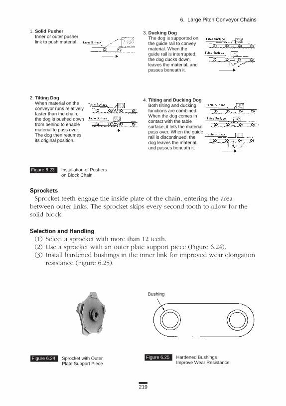
219
6. Large Pitch Conveyor Chains
SprocketsSprocket teeth engage the inside plate of the chain, entering the area
between outer links. The sprocket skips every second tooth to allow for thesolid block.
Selection and Handling(1) Select a sprocket with more than 12 teeth.(2) Use a sprocket with an outer plate support piece (Figure 6.24). (3) Install hardened bushings in the inner link for improved wear elongation
resistance (Figure 6.25).
Figure 6.23 Installation of Pushers on Block Chain
Figure 6.24 Sprocket with Outer Plate Support Piece
Figure 6.25 Hardened BushingsImprove Wear Resistance
Bushing
1. Solid PusherInner or outer pusher link to push material.
2. Tilting DogWhen material on the conveyor runs relatively faster than the chain, the dog is pushed down from behind to enable material to pass over.The dog then resumes its original position.
3. Ducking DogThe dog is supported onthe guide rail to convey material. When the guide rail is interrupted, the dog ducks down, leaves the material, and passes beneath it.
4. Tilting and Ducking DogBoth tilting and ducking functions are combined.When the dog comes in contact with the table surface, it lets the material pass over. When the guide rail is discontinued, the dog leaves the material, and passes beneath it.

220
Applications
6.3.7 Sewage Treatment Chain (Rectangular Sludge Collector)
Large conveyance: Sewage treatment equipment
Application ExampleOne of main uses of large pitch conveyor chain is in water treatment facili-
ties. In a large sewage treatment facility, sewage goes through several tanks inwhich solid wastes are eliminated by deposition and flotation.
In the silt tank, sand and dirt are removed using vacuum or V-buckets. In thesettling tank, sludge in the water, or on its surface, is scraped to the exit with“flights” (boards) installed between two strands of chains at intervals of 3 m(Figure 6.26). Sewage Treatment Chain (ACS Chain) is used in this process(Figure 6.27). Accumulated dirt is removed with pumps.
Cast iron chains were once used in sewage treatment facilities. In such a cor-rosive environment, chain deterioration could not be avoided. As the volumeof chain material decreased due to corrosion, wear was accelerated. To offsetthe loss of material due to corrosion, cast iron chains became quite heavy, yetthe tension required in water-treatment applications did not justify the use of achain with such high tensile strength.
In the mid-1960s, ACS stainless steel chains were developed in Japan espe-cially for water treatment facilities. The stainless steel construction assuredexcellent corrosion resistance, so there was no need for extra-heavy cast ironchains. Because of their superior functions, ACS chains have gained wideacceptance.
This chain is also used to convey corrosive objects in general scraper conveyors.
Figure 6.26 Sewage Treatment Chain with Flights Installed

221
6. Large Pitch Conveyor Chains
Construction and FeaturesACS Chain has large-diameter bushings. It does not have rollers.Plates, pins, and bushings are made of 403 stainless steel. The T-head cotter
key is made of 304 stainless steel, which ensures high corrosion resistance.SF-4 attachments are used for installing flights, and extended pins or LA-1
attachments for installing buckets in the dredger. Both of these attachmentsare placed on the outer plates. LA-1 attachments are made of heat-treated car-bon steel.
Figure 6.28 compares the strength of cast iron chain and stainless steel chainin a long-term test.
Figure 6.27 Sewage Treatment Chain
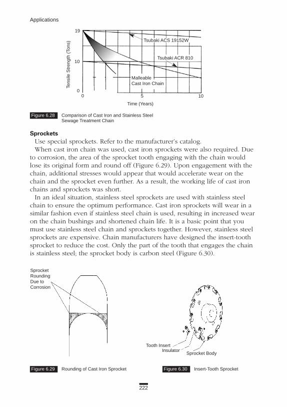
Figure 6.28 Comparison of Cast Iron and Stainless Steel Sewage Treatment Chain
222
Applications
SprocketsUse special sprockets. Refer to the manufacturer’s catalog.When cast iron chain was used, cast iron sprockets were also required. Due
to corrosion, the area of the sprocket tooth engaging with the chain wouldlose its original form and round off (Figure 6.29). Upon engagement with thechain, additional stresses would appear that would accelerate wear on thechain and the sprocket even further. As a result, the working life of cast ironchains and sprockets was short.
In an ideal situation, stainless steel sprockets are used with stainless steelchain to ensure the optimum performance. Cast iron sprockets will wear in asimilar fashion even if stainless steel chain is used, resulting in increased wearon the chain bushings and shortened chain life. It is a basic point that youmust use stainless steel chain and sprockets together. However, stainless steelsprockets are expensive. Chain manufacturers have designed the insert-toothsprocket to reduce the cost. Only the part of the tooth that engages the chainis stainless steel; the sprocket body is carbon steel (Figure 6.30).
19
10
00 5 10
Tsubaki ACR 810
Tsubaki ACS 19152W
Malleable Cast Iron Chain
Time (Years)
Tens
ileS
tren
gth
(Ton
s)
Figure 6.29 Rounding of Cast Iron Sprocket Figure 6.30 Insert-Tooth Sprocket
SprocketRoundingDue toCorrosion
Tooth InsertInsulator
Sprocket Body

223
6. Large Pitch Conveyor Chains
Selection and Handling(1) The chain speed of a scraper application is slow, 0.3 to 0.6 m/min., and
3 m/min. in the bucket application. The chain tension is the highest dur-ing the test period, before water is poured into the tank. Before water ispoured into a 40-m tank, one chain is exposed to tension of 10 kN.
(2) 403 stainless steel chain has sufficient corrosion resistance for mostsewage facilities. If there is a high concentration of chlorine (as found insea water, for example), if there are high levels of sulfur from hotsprings, or if the tanks are contaminated, 304 stainless steel should beused, at least for side plates.
Chains for Special ApplicationsChains used in water treatment applications are operated at low speeds and
not subjected to any heavy shock loads. It is not necessary in this applicationto consider chains with tensile strength greater than 19 tonf.
For that reason the following chains were developed:(1) ACR 810 Chain is a small chain made of 403 stainless steel. It has a ten-
sile strength of 10 tonf. This was the first chain to be used in scraperapplications to be equipped with rollers. The rollers reduce wear on thesprocket and the chain. Insert-tooth sprockets have been developed forthis chain as well. (See Figure 6.30.)
(2) Engineered plastic chain (ACP Chain, Figure 6.31), developed in theUnited States, is a light-weight chain with high corrosion resistance. Itdoes not have rollers (similar to cast iron chain). Due to its light weight(one-half to one-fourth the weight of stainless steel chain), installation isrelatively simple.
One of the problems with this chain is that engineered plastic expandsand contracts as the water temperature changes. Therefore, it is difficult to keep the chain under constant tension. Tensile strength (25 to 40 kN) is much lower than either cast iron or stainless steel chain.

Figure 6.32 Sprocket for Engineered Plastic Chain
224
Applications
The material, strength, and dimensions of engineered plastic chains differ from one manufacturer to another. Compare these points when you select the chain.
For engineered plastic chains, there are plastic kits, which include sprockets, flights, and shoes (see Figure 6.32). Use them together. Never use cast iron sprockets with engineered plastic chain.
Figure 6.31 Engineered Plastic Chain (ACP Chain)

225
6. Large Pitch Conveyor Chains
6.3.8 Sewage Treatment Chain (Bar Screen) Large conveyance: Sewage treatment equipment
Application ExampleAt the water gate of sewage treatment plants, there are gratings—called bar
screens—arranged lengthwise to catch floating objects. In addition to watertreatment plants, bar screens may be installed at the mouths of rivers. In somebar screen setups, chains are set on guide rails and used as wide gratings orscreens. (See Figures 6.33 and 6.34.)
Eventually gratings fill up with contaminants, and they have to be cleaned. A comb-shaped rake installed between two strands of chain is used for thispurpose.
Figure 6.33 Bar Screen Chain Set-up Figure 6.34 Bar Screen Chain
Sprocket
Bar Screen Chain forSewage Removal

Table 6.5 Specifications for Bar Screen Chain
Side Plate Pin, Bushing, Roller
Standard Series Heat-Treated Steel Heat-Treated 400 Series Stainless SteelPJ Series Heat-Treated 400 Series Stainless Steel Heat-Treated 400 Series Stainless SteelSJ Series 304 Stainless Steel 304 Stainless Steel
Figure 6.35 PJW-Specification Bar Screen Chain
Figure 6.36 Y Attachment
Figure 6.37 A-2 (Type I) Attachment
226
Applications
Construction and Features(1) Bar Screen Chain is constructed like roller chain. There are three specifi-
cations in this kind of chain. Select the appropriate type based on thecorrosiveness of the operating environment (Table 6.5).
(2) Available attachments—Y and A-2 (Type I)—are made of heat-treatedsteel.
(3) S-rollers and F-rollers may be used with this chain. The differencebetween the two include the following points:S-roller: Adapted to a rake with wheels. The rake rotates and sweeps out the waste. (This is sometimes called a rotating-rake design.) F-roller: Adapted to the rake without wheels. The rake is fixed on the chain. The F-rollers support the weight of the rake. In an F-roller set-up, the flange may alternate sides every one or two rollers. This arrangementprevents derailment. Because the inside width (W) of the chain is larger with the F-roller, the chain is called PJW specification to distinguish it from others (Figure 6.35). Each chain attachment is exposed to high load, because there are only two or three rakes installed on the chain. Y attachments are used in the rotating-rake design (Figure 6.36), and A-2(Type I) attachments are used in the fixed rake type (Figure 6.37). Both attachments have additional features that increase their strength: the end of the connecting pin is threaded and equipped with a nut to prevent falling off.

227
6. Large Pitch Conveyor Chains
(4) F-rollers are exposed to extremely high load from the rakes attached to the chain. To extend the working life, bushings usually have a larger bearing area, which reduces bearing pressure.
(5) Common chain sizes have tensile strength within the range of 68 to 490 kN.
SprocketsAlthough these chains are based on RF conveyor chain, they require special
sprockets because of the pitch (152.4mm = 6 inches). For S-roller type, insert-tooth sprockets are available.
Selection and Handling(1) To select this chain, verify the chain tension required, and make sure to
confirm the roller load and attachment strength (twisting moment andbending moment).
(2) Allow for a safety factor to withstand peak loads during jam-ups. (3) Chain rollers might be exposed to high loads when following the curves
of the guide rail. Make sure you take this load into consideration whenselecting the chain. Minimize tension from the take-up (Figure 6.38).
(4) Of course, you should avoid contaminating the water with oil, but whenthe test run of the equipment is performed without water, the chain’smoving parts should be lubricated.
Technical TrendsBar Screen Chain is required to perform with low noise levels, because it is
now commonly used near populated areas.
Figure 6.38 High Roller Load Due to Curved Rail
Corner Rail
Roller Load

228
Applications
6.4 STANDARD ATTACHMENTSLarge pitch conveyor chains are usually used with attachments. These attach-
ments are divided into the following categories: • Standard• Industry-specific (Plus α Alpha)• Special Attachment styles and nomenclature for large pitch chains are the same as
for small pitch chain. (See Applications Sections 2.3 to 2.5.)The standard attachments for large pitch conveyor chains are A, K, SA, SK,
G, and RFD type. These attachments are available on the following types ofchains:
• Treated surface, such as plated chain.• 304 stainless steel or other special materials.• Bearing roller or bearing bush specification.
1. A attachment2. K attachment3. SA attachment4. SK attachment5. G attachmentOne plate in a pair has bolt holes. These are used to install buckets on two
sets of chains (Figure 6.39).
Refer to Applications Section 2.3 for descriptions of these types of attachments.
Figure 6.39 G-4 Attachments

229
6. Large Pitch Conveyor Chains
6. RFD attachmentsThe upper side of the link plate is tall; it actually sticks above the R-roller
(Figure 6.40). Therefore, conveyed objects can be placed directly on the chain.This is a very economical design.
6.5 PLUS αα ALPHA ATTACHMENTSAlthough these are not standard attachments, tooling is available. They have
been used in a variety of applications, and they have proven to be effective.Please try to incorporate them in your designs.
These attachments are also available with the chains shown below:• Treated-surface type, such as plated chain.• 304 stainless steel or other special materials.• Bearing roller or bearing bush specification.
Tables 6.6, 6.7, and 6.8 show the major types of industry-specific attachments.
Figure 6.40 RFD Attachments

230
Applications
Table 6.6 Plus αα Alpha Attachments
Usage orChain Name Attachment Appearance Application
With CA2 CA2
With AA3 AA3
With Reinforced Rib A2R
With MG2 MG2
With AS2 AS2
With AF2 AF2
With Centered Bushing CB
With WS WS
EP1With Extended Pin EP2
EP3
With Stay-Pin TN
With KY KY1KY2
For a net conveyor that haslimited clearance betweenslats next to each other atsprocket engagement.
To have a reinforced attach-ment, inserting conveyedjigs into it.
To have high flexural rigidityof A attachment.
The same size bucket canbe installed.
For installing scrapers orflights.
For installing deep scrapersor flights.
Bars penetrating a chain tobe installed.
For prevention of conveyedmaterials leakage.
A hollow pipe or somethingto be installed on edge ofthe pin.
Material to be put directlyon stay-pins or wire meshlaced around pins.
For storage of cyclindricalmaterials.
Type 2Type 1
There are two types depending on open and closed position of the attachment.

With Top Plate TP1TP2
With Trolley Roller TRO
Resists Stick Slip RFL
OR1With Outboard Roller OR2
OR3
With Stud Bushings RFB
With Center Roller CRRCRF
With Guide Shoe GSAGSK
With Guide Roller GR
With Solid Pusher KD1KD2
KD1: Dog not attached to plate.KD2: Dog attached to plate.
With Dog Roller RD
When cylindrical materials are conveyed, material surface is not damaged, and rotating friction is reduced by using this attachment.
231
6. Large Pitch Conveyor Chains
Table 6.7 Plus αα Alpha Attachments
Not to damage conveyedmaterials.
For long-distance and hori-zontal conveying.
For smooth conveying with-out stick slipping.
For supporting heavy loads.
For longer wear life of bush-ing.
For easy replacement ofroller when it is worn.
For prevention of chain’swinding travel.
For horizontal conveying.
To push materials with thepusher.
To convey cylindrical materials by pushing.
Table Surface
Table Surface
Direction of Travel

232
Applications
Table 6.8 Plus αα Alpha Attachments
With Tilting Dog CD
With Roller Tilting Dog RCD
With Ducking Dog DD
With Teeth Dog TD
With ID ID
When material on the conveyor runs relatively fasterthan the chain, the dog is pushed down from behind toenable material to pass over. The dog then resumes itsoriginal position.
When the conveyor runs on descent, the dog preventsthe cylindrical material from excessive run. When thematerial is in front of the dog, the dog is pushed downand can store the material.
The dog is supported on the guide rail to convey materi-al. When the guide rail is interrupted, the dog ducksdown, leaves the material, and passes beneath it.
The dog functions best when the chain conveys thematerial on descent, preventing it from excessive runand storing it. As the dog resumes its original position atthe engagement of a sprocket tooth, it does not damagethe material and makes little noise.
At the time that the dog pushes the material, if unex-pected load operates the dog, it ducks down, leaving thematerial as it passes beneath it.
For storage of materials onthe table surface.
For storage of cylindricalmaterials.
For leaving materials at thedesignated station.
For storage of cylindricalmaterials without noise.
For both storage and pushing.
Table Surface
Table Surface
Table Surface
Table Surface
Table SurfaceStopper
Stopper
Stopper
Direction of Travel (in case of storage)
Direction of Travel (in case of storage)
Direction of Travel
Direction of Travel
Direction of Travel
Materials

233
6. Large Pitch Conveyor Chains
6.6 SPECIAL ATTACHMENTSSpecial attachments are designed for specific applications and are used infre-
quently. In Applications Section 2.5, we discussed who should make specialattachment—the chain manufacturer or the user. Please refer to the section fordetails.
For large pitch conveyor chain, the tolerance of the height of a ground A or K attachment from the guide rail to the upper side of the “PrecisionGround” attachment is ± 0.4 mm. This value is larger than the tolerance for RSconveyor chains.
Figure 6.41 shows examples of special attachments.
Figure 6.41 Examples of Special Attachments

234
BIBLIOGRAPHY1. Atsushi Okoshi, Roller Chain, Korona-sha, Japan (1960).2. Masataka Nakakomi, Safety Design of Roller Chain, Yoken-do,
Japan (1989).3. Shizuo Aoi, Chain Conveyor, Yakumo-shoten, Japan (1958).4. Utaro Majima, Chain-Conveyor, Kogaku Tosho, Japan (1967).5. R. C. Binder, Mechanics of the Roller Chain Drive, Prentice-Hall, Inc.,
NJ (1956).6. L. Jones (Ed.), Mechanical Handling with Precision Conveyor Chain,
Hutchinson & Co., London (1971).7. L. L. Faulkner, S. B. Menkes (Ed.), Chains for Power Transmission and
Material Handling, Marcel Dekker (1982). 8. Hans-Guenter Rachner, Stahlgelenkketten und Kettentriebe, Springer-
Verlag, Berlin (1962).9. Catalog, Tsubakimoto Chain Co.10. Catalog, Daido Kogyo.11. Catalog, Izumi Chain.12. Catalog, Borg-Warner Automotive. 13. Catalog, Rexnord.14. Catalog, Renold.

235
Coffee Break
Coffee Break The Tools Developed from Chain
Here we show three unique tools developed from chains.
1. Tough Roller (Figure 1)This tool consists of a frame and an endless assembly of rollers wrapping
around a center plate in the frame.Comparing Tough Roller design to general roller bearing, the center plate in
the frame works as an inner ring, and the surface on which the Tough Rollertravels acts as an outer ring. Rollers function like cylindrical roller bearings,and the plate, together with the pin, act as a retainer. Due to its features, likehigh capacity (maximum allowable load = 100 tons) for its small body size,small running friction and low center of gravity, this tool is used in low-fre-quency conveyance of heavy objects.
2. Shafted Bearing Roller (Figure 2)In this bearing roller, the roller has a shaft installed on it, which permits use
as a support or guide wheel.There are a variety of sizes and options available in this construction. Roller
diameters range from 31.8 to 125 mm; maximum allowable load from 1.27 to27.5 kN. The roller can be an R-type or F-type. There are various options, suchas a urethane coating applied to the outer surface, or there can be a 5-degreetaper in the channel.
3. Attachment with Shafted Bearing RollerIn this bearing roller, the roller is attached to the K-1 attachment of the
chain. It can be used as support or a guiding wheel. Capacity and specifica-tions are the same as for the shafted bearing roller.
Figure 1 Tough Roller Figure 2 Shafted Bearing Roller
Top Plate
CenterPlate
SidePlate

236
Coffee Break
Coffee Break Sizing Up Chain
1. Teeny TinyThe smallest standard transmission chain is Number 25. The chain pitch is
6.35 mm and minimum tensile strength is 3.50 kN. The smallest chain current-ly manufactured, although it is not standard, is Number 10, which is used inoffice equipment. It has a pitch of 3.175 mm and minimum tensile strength of0.98 kN. There are a lot of micromachines (less than 1 mm) being made, butthe chain to fit them is not currently available.
2. StupendousThe largest standard transmission chain is Number 240, which has a pitch of
76.2 mm and average tensile strength of 500.4 kN. There are larger chains, butthey are not standard. A Number 400, for example, has a pitch of 127 mm andaverage tensile strength of 1,730 kN. Multistrand versions of this chain areavailable, as well, from some manufacturers. Their tensile strengths are themultiplication of a single strand. Check with your manufacturer for availability.
The largest chain ever used had a pitch of 1,400 mm. It was created for hori-zontal rotating parking equipment.
The highest average tensile strength for a single chain—900 tonf—was ablock chain. It was used in the production of steel tubing. If this chain were tobe used in a multistrand configuration, its average tensile strength would bemultiplied.
However, considering the cost, tensile strength of 500 tonf is the limit for asingle roller chain.

237
Coffee Break
Coffee Break Speed Variation
Chains are usually used at low speeds with large loads. Some common chaintypes and speeds include the following:
Transmission roller chain: less than 150 m/min. Small pitch conveyor chain: 10 to 30 m/min.Precision conveyor chain: less than 50 m/min.Top chain: 10 to 30 m/min.Free flow chain: 5 to 10 m/min.Large pitch conveyor chain: 10 to 30 m/min.
There are chains that are designed for high-speed operations. Here are someexamples:
• The chain used in balancer drives in automotive engines can run at 1,800 m/min., which is the same speed as a cog belt. Chain pitch is lessthan 8 mm.
• Chain that drives the rear wheels of racing motorcycles operates at 1,500m/min.
• The chain for the camshaft drives in marine diesel engines operates atabout 600 m/min. Chain pitch is greater than 100 mm.
• The top chain that moves beer cans in breweries runs at 200 m/min.• Large pitch conveyor chains and block chains in steel processing plants
can run at speeds of 330 m/min. The chain pitch is 150 mm.
In each of these high-speed operations, the chain must be selected carefully.It’s important to consider not only the strength and wear resistance, but thetype of lubrication required. When you set up a high-speed chain system,make sure you work with a reliable supplier, and ask to see some actual per-formance results for the chain you are considering.

238

239
AFTERWORDFor designers and users of equipment, the most important points to consider
for power transmission and conveyor operations are how well they stand upto and satisfy the following:
Power Transmission Operations 1. Quality: The features of the transmitted power, maintenance, length
of working life.2. Cost: Initial cost, running cost.3. Delivery: Availability.
Conveyor Operations 1. Quality: Speed, accuracy, flexibility, maintenance, length of working life.2. Cost: Initial cost, running cost.3. Delivery: Availability.
Of course, these points can be applied to much more than just chain. You also have to compare belts, gears, and even other tools.
Power transmission and conveyors are rarely treated scientifically. At collegesand universities, chains are often ignored in lectures about technology. Manypeople think that chain is simply an old machine element.
But chain is more than that. Used correctly, chain can have a major impact on the entire operation. Here’s an example: By replacing steel rollers with engineered plastic rollers on conveyor chains and moving from plastic rollers to bearing rollers, the coefficient of friction was reduced to one-fourth or one-fifth of the original. This results in lower costs for driving parts and frames, and saves energy. Progress in chains has a direct connection to economizingenergy.
I have worked with many customers in many different fields during mycareer. I noticed that there was no handbook to explain the different types ofchains, nor a book that describes the ease and convenience of using chain.
This book is designed to solve these problems. First, I explained the mainideas about chain. Then, I picked 50 types of chain in current use and gavepractical points—application examples, construction and features, sprockets,selection and handling, technical trends—so that readers can work the chain’sability fully into their equipment. There is no denying the fact that most of thechain names and types are products of Tsubaki. Although other manufacturersalso produce most of the chain types shown in this book, the lack of materialsand the wide variation in products make comparisons very difficult.

240
I wish to express my sincere thanks to Mr. Toshiharu Yamamoto, the late Mr.Katsumi Kotegawa, and other senior experts who developed the company’stechnology, Mr. Keichi Sawata, Mr. Sumio Watanabe, Mr. Shinobu Takeda, Mr.Susumu Saijo (who provided good materials), and Mr. Tadahisa Yoshida forvaluable advice.
May 1995Makoto Kanehira

9 780965 893206
52995>ISBN 0-9658932-0-0
$29.95L10970