seventeenth lrfd specifications statewide for … cell box culvert under existing road &...
TRANSCRIPT

Seventeenth Statewide Conference on Local BridgesTuesday, October 25, 2011
Training Session: Culvert Design, Analysis - talk 3
Presented by: Rajesh Taneja, P.E. NYSDOT
LRFD SPECIFICATIONS for
BURIED STRUCTURES
Live Load Distribution
October 25, 2011
Rajesh Taneja Department of Transportation State of New York
State of New York Department of Transportation
State of New York Department of Transportation
Buried Structure: A generic term for a structure built by embankment or trench methods. Tunnel: A horizontal or near horizontal opening in soil excavated to predesigned geometry by tunneling methods exclusive of cut-and-cover methods. Materials: Aluminum, Cast-In-Place Concrete & Precast Concrete, Steel, Thermoplastic Pipe
LRFD Section 12 BURIED STRUCTURES AND
TUNNEL LINERS
Metal Pipes / Structural Plate Pipe / Structure Plate Box Reinforced Concrete Pipe
Reinforced Concrete Cast-In-Place & Precast
Arch, Box, Elliptical
Thermoplastic Pipe
State of New York Department of Transportation

Limit State & Resistance Factors Rr = Ф Rn ; ∑ηiγiQi ≤ Ф Rn = Rr
Rr – Factored Resistance
Rn – Nominal Resistance
Ф – Resistance Factor (Table 12.5.5.1) γ – Load Factor ; Q – Force Effect
Table 12.5.5.1 (Ф Value)
State of New York Department of Transportation
Flexure Shear
C.I.P Box Structures 0.90 0.85 Precast Box 1.00 0.90
Precast 3-sided Structure
0.95 0.90
Section 12.11
Precast Box Culverts Reinforced Cast-in-place Box Culverts
Reinforced Cast-in-place Arches
Section 12.14
Precast Reinforced Concrete Three-Sided Structures
State of New York Department of Transportation
Section 12.6 General Design Features
Loading Horizontal & Vertical Earth Pressure Pavement Load Live Load Earth Surcharge, LL Surcharge, Downdrag Loads
External Hydrostatic Pressure / Water Buoyancy Loads
Earthquake Loads, Uplift, Minimum Soil Cover
State of New York Department of Transportation
Service Limit State (Table 3.4.1-1)
Deflection
Crack Width in Reinforced Concrete Structures
State of New York Department of Transportation
Strength Limit State (Table 3.4.1-1)
Load Combinations I & II

Section 12.11 (Box Culverts)
LL Distribution
Section 12.14 (3-Sided Units)
LL Distribution
State of New York Department of Transportation
Side Walls & Bottom Slab 12.11.2.3
Same as Top Slab 12.11.2.1
Skew 12.11.2.4
12.11.2.3 Provisions need not be corrected.
Edge Beam / Shear Transfer across Joints 12.11.2.1
4.6.2.10.4 & 4.6.2.1.4
Service Limit State (Crack Width Control) 12.11.3
5.7.3.4
Sides 12.14.5.2
Same as Top Slab (Box Culverts) 12.11.2.1
Skew 12.14.5.3
> 15 ̊; Effect of Skew shall be considered in analysis
Shear Transfer across Joints 12.14.5.4
4.6.2.10.4 & 12.4.5.4 additional requirements
Deflection Control at the Service Limit State 12.14.5.9
2.5.2.6.2 Provisions are mandatory
3.6.1.2.6 Distribution of Wheel Load Through Earth Fills
For Df (Fill Depth) ≥ 2.0 '
Distributed Rectangular Area = [ L+(1.15 or 1.0) * D f ] x [ W+(1.15 or 1.0) * D f ] Factor 1.15 for Select Granular Backfill & 1.0 for fill in all other cases
3.6.1.1.2 - Multiple Presence Factor
3.6.2.2 - Dynamic Load Allowance
State of New York Department of Transportation
Live Load 3.6.1.2 Design Vehicular LL
Design Truck or Design Tandem Design Lane Load
Each design lane (either design truck or tandem + lane load) The loads assumed to occupy 10.0 ‘ transversely within a
design lane
State of New York Department of Transportation
3.6.1.2.5 Tire Contact Area (Wheel; 1 or 2 tires) TRAFFIC DIR. W L=10 “ W=20 “ L
Section 12.11 (Box Culverts)
12.11.2.1 – Top Slab LL
Distribution
Section 12.14 (3-Sided Units)
12.14.5 - Design
State of New York Department of Transportation
Loads & Load Combinations
Table 3.4.1-1
Application of Live Load
3.6.1.3
Df < 2.0 feet (Fill Depth)
4.6.2.10
Df ≥ 2.0 feet 3.6.1.2.6
IM (Dynamic Load allowance) IM=33(1.0-0.125)DE
3.6.2.2
Edge Beam / Shear Transfer across Joints
4.6.2.10.4 & 4.6.2.1.4
Top Slab LL Dist. 12.11.2.1
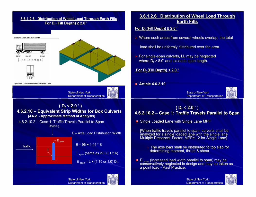
3.6.1.2.6 Distribution of Wheel Load Through Earth Fills
For Df (Fill Depth) ≥ 2.0 '
Where such areas from several wheels overlap, the total load shall be uniformly distributed over the area. For single-span culverts, LL may be neglected where Df > 8.0’ and exceeds span length. For Df (Fill Depth) < 2.0 ‘
Article 4.6.2.10
State of New York Department of Transportation
( Df < 2.0 ‘ ) 4.6.2.10.2 – Case 1: Traffic Travels Parallel to Span
Single Loaded Lane with Single Lane MPF [When traffic travels parallel to span, culverts shall be
analyzed for a single loaded lane with the single lane Multiple Presence Factor, MPF=1.2 for Single Lane]
The axle load shall be distributed to top slab for
determining moment, thrust & shear. E span (Increased load width parallel to span) may be conservatively neglected in design and may be taken as a point load - Past Practice.
State of New York Department of Transportation
State of New York Department of Transportation
( Df < 2.0 ‘ ) 4.6.2.10 – Equivalent Strip Widths for Box Culverts [4.6.2 - Approximate Method of Analysis] 4.6.2.10.2 – Case 1: Traffic Travels Parallel to Span
E
Traffic
Opening
E span
E – Axle Load Distribution Width
E = 96 + 1.44 * S E span (same as in 3.6.1.2.6) E span = L + (1.15 or 1.0) D f
3.6.1.2.6 Distribution of Wheel Load Through Earth Fills For Df (Fill Depth) ≥ 2.0 '
State of New York Department of Transportation

State of New York Department of Transportation
( Df < 2.0 ‘ ) 4.6.2.10 – Equivalent Strip Widths for Box Culverts [4.6.2 - Approximate Methods of Analysis] 4.6.2.10.3 – Case 2: Traffic Travels Perpendicular to Span
Confusing Case; Refers to 4.6.2.1 [4.6.2.1 – Decks & under 4.6.2]
In decks, we can have Primary Span Strip perpendicular to Direction of Traffic
Culvert Unit
State of New York Department of Transportation
40 foot span
( Df < 2.0 ‘ ) 4.6.2.10.3 – Case 2: Traffic Travels Perpendicular to Span (4.6.2.1 Article)
20 foot span
45 foot span In this case, culverts can have two or more trucks on the same design strip at the same time. This effect is to be considered along with M.P.F. (Multiple Presence Factor) State of New York
Department of Transportation
( Df < 2.0 ‘ ) 4.6.2.10.3 – Case 2: Traffic Travels Perpendicular to Span (4.6.2.1 Article)
Traffic
Opening E span
E – Axle Load Distribution Width
E = 26.0 + 6.6 * S (+M) E = 48.0 + 3.0 * S (-M)
E
In this case, culverts can have two or more trucks on the same design strip at the same time. This effect is to be considered along with M.P.F. (Multiple Presence Factor)
State of New York Department of Transportation
4.6.2.10.2 – Case 1: Traffic Travels Parallel to Span ( Df < 2.0 ‘ )
20 foot span
40 foot span
State of New York Department of Transportation
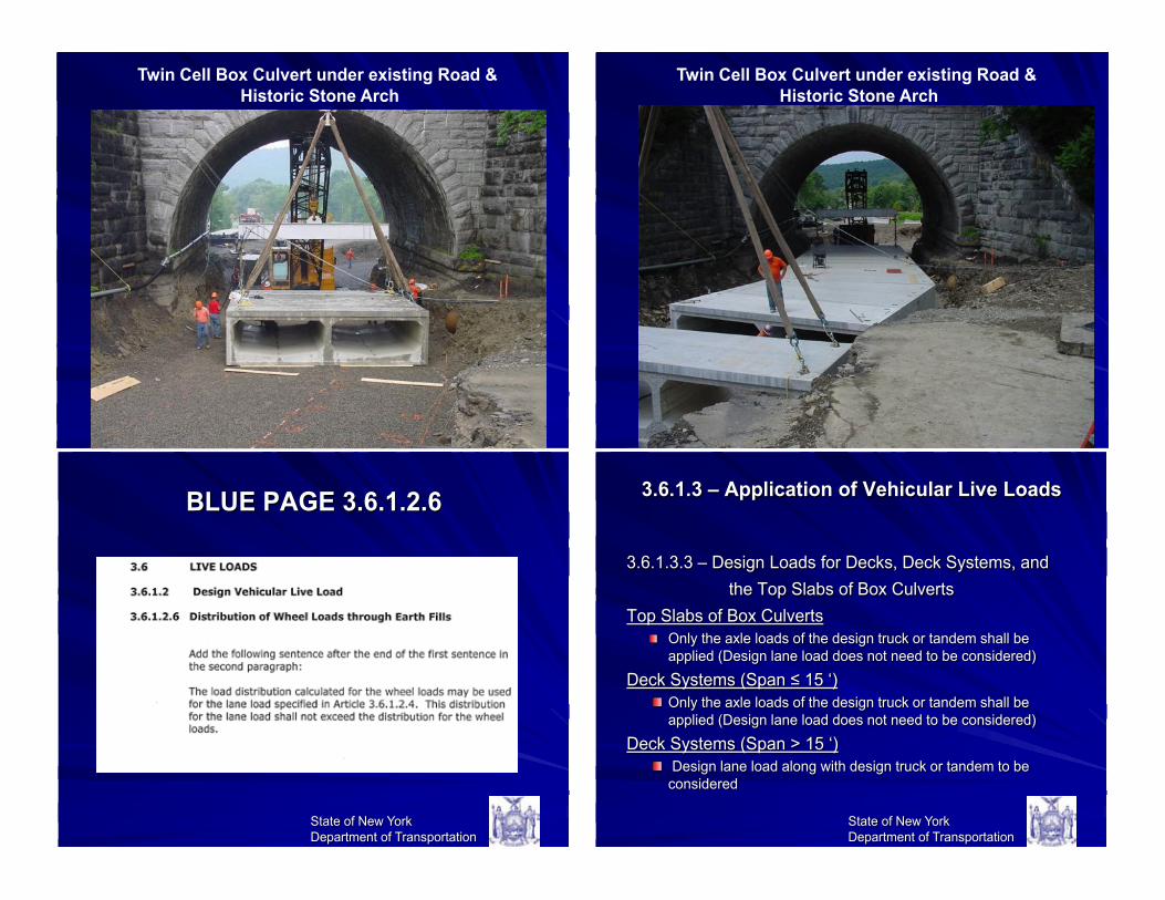
Twin Cell Box Culvert under existing Road & Historic Stone Arch
3.6.1.3 – Application of Vehicular Live Loads
3.6.1.3.3 – Design Loads for Decks, Deck Systems, and the Top Slabs of Box Culverts
Top Slabs of Box Culverts Only the axle loads of the design truck or tandem shall be applied (Design lane load does not need to be considered)
Deck Systems (Span ≤ 15 ‘) Only the axle loads of the design truck or tandem shall be applied (Design lane load does not need to be considered)
Deck Systems (Span > 15 ‘) Design lane load along with design truck or tandem to be considered
State of New York Department of Transportation
BLUE PAGE 3.6.1.2.6
State of New York Department of Transportation
State of New York Department of Transportation
Twin Cell Box Culvert under existing Road & Historic Stone Arch
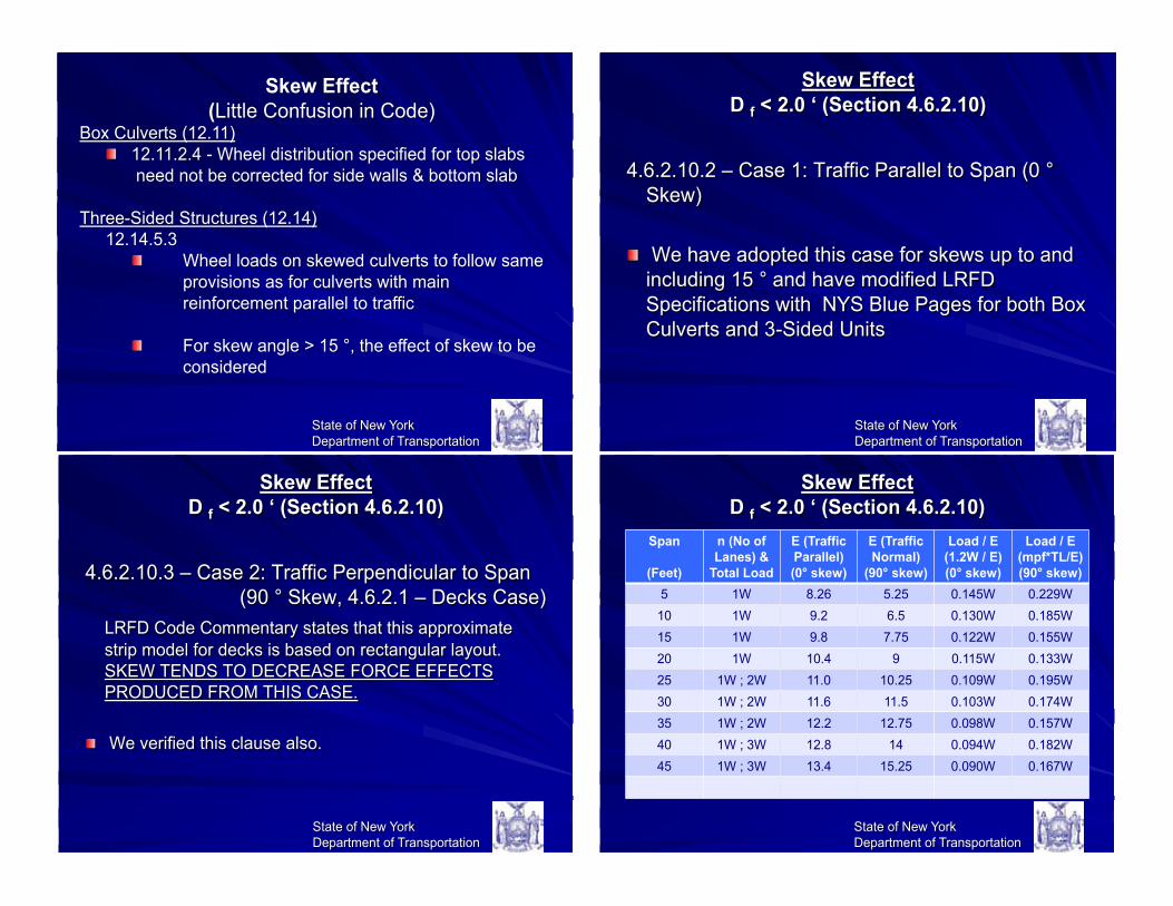
Skew Effect D f < 2.0 ‘ (Section 4.6.2.10)
4.6.2.10.2 – Case 1: Traffic Parallel to Span (0 ° Skew)
We have adopted this case for skews up to and including 15 ° and have modified LRFD Specifications with NYS Blue Pages for both Box Culverts and 3-Sided Units
State of New York Department of Transportation
Skew Effect D f < 2.0 ‘ (Section 4.6.2.10)
State of New York Department of Transportation
Span
(Feet)
n (No of Lanes) &
Total Load
E (Traffic Parallel) (0° skew)
E (Traffic Normal)
(90° skew)
Load / E (1.2W / E) (0° skew)
Load / E (mpf*TL/E) (90° skew)
5 1W 8.26 5.25 0.145W 0.229W 10 1W 9.2 6.5 0.130W 0.185W 15 1W 9.8 7.75 0.122W 0.155W 20 1W 10.4 9 0.115W 0.133W 25 1W ; 2W 11.0 10.25 0.109W 0.195W 30 1W ; 2W 11.6 11.5 0.103W 0.174W 35 1W ; 2W 12.2 12.75 0.098W 0.157W 40 1W ; 3W 12.8 14 0.094W 0.182W 45 1W ; 3W 13.4 15.25 0.090W 0.167W
Skew Effect D f < 2.0 ‘ (Section 4.6.2.10)
4.6.2.10.3 – Case 2: Traffic Perpendicular to Span (90 ° Skew, 4.6.2.1 – Decks Case)
LRFD Code Commentary states that this approximate strip model for decks is based on rectangular layout. SKEW TENDS TO DECREASE FORCE EFFECTS PRODUCED FROM THIS CASE.
We verified this clause also.
State of New York Department of Transportation
State of New York Department of Transportation
Skew Effect (Little Confusion in Code)
Box Culverts (12.11) 12.11.2.4 - Wheel distribution specified for top slabs
need not be corrected for side walls & bottom slab
Three-Sided Structures (12.14) 12.14.5.3
Wheel loads on skewed culverts to follow same provisions as for culverts with main reinforcement parallel to traffic
For skew angle > 15 °, the effect of skew to be
considered

BLUE PAGE 12.11.2.1
State of New York Department of Transportation
Skew Effect D f ≥ 2.0 ‘ (Section 3.6.1.2.6)
For all cases of any skew angle: Area=[L+(1.15 0r 1.0)Df] x [W+(1.15 or 1.0)Df]
State of New York Department of Transportation
BLUE PAGE 12.14.5.3
State of New York Department of Transportation
Skew Effect D f < 2.0 ‘ (Section 4.6.2.10)
4.6.2.10.3 – Case 2: Traffic Perpendicular to Span (90 ° Skew, 4.6.2.1 – Decks Case)
We have adopted this case for all skews > 15 ° and have modified LRFD Specifications with NYS Blue Pages for both Box Culverts and Three-Sided Units
State of New York Department of Transportation

Shear Transfer in Transverse Joints / Edge Beams
4.6.2.10.4 (12.11.2.1) – Precast Box Culverts
Span / Thickness (s/t) ≤ 18 & Segment Length ≥ 4 ‘ Shear Transfer across the joints need not be provided
If above requirements are not satisfied Provide the culvert with a means of shear transfer
between adjacent sections. Shear transfer may be provided by pavement, soil fill or physical connection.
Design the Section Ends as Edge Beam (4.6.2.1.4)
State of New York Department of Transportation
12.11.2.2 – Modification of Earth Loads (DL)
State of New York Department of Transportation
Embankment Condition: WE = Fe γs Bc H (12.11.2.2.1-1) Fe = 1 + 0.20 * H / Bc (12.11.2.2.1-2) Trench Condition: WE = Ft γs Bc H (12.11.2.2.1-3) Ft = [(Cd Bd
2) / (H Bc)] ≤ Fe (12.11.2.2.1-4)
Shear Transfer in Transverse Joints
12.14.5.4 – Precast Reinforced Concrete 3-Sided Structures
4.6.2.10.4 Provisions shall apply (for Box Culverts)
Additionally, shear transfer to be provided in top slabs for Df < 2.0 ‘ & subjected to vehicular LL unless
t (slab thickness) ≥ (S+10) / 30
These requirements are for Flat Top Structures and do not apply to Arch-Top Structures.
State of New York Department of Transportation
Section 12.11 (Box Culverts)
LL Distribution
Section 12.14 (3-Sided Units)
LL Distribution
State of New York Department of Transportation
Side Walls & Bottom Slab 12.11.2.3
Same as Top Slab 12.11.2.1
Skew 12.11.2.4
12.11.2.3 Provisions need not be corrected.
Edge Beam / Shear Transfer across Joints 12.11.2.1
4.6.2.10.4 & 4.6.2.1.4
Sides 12.14.5.2
Same as Top Slab (Box Culverts) 12.11.2.1
Skew 12.14.5.3
> 15 ̊; Effect of Skew shall be considered in analysis
Shear Transfer across Joints 12.14.5.4
4.6.2.10.4 & 12.4.5.4 additional requirements

QUESTIONS FOR PDF
1. In general for the design of buried structures, what load combinations for Strength Limit State Design are considered?
2. As per code for the design of buried structures, when do we consider earthquake loads?
3. In LRFD Specifications, what magnitude of ‘Fill Depth’ differentiates the Live Load Distribution Criteria for culverts?
State of New York Department of Transportation
Thank you
State of New York Department of Transportation
QUESTIONS FOR PDF 4. In LRFD Specifications to incorporate skew effects, what
magnitudes of skew angles are to be considered in analysis?
5. For a no skew case or when traffic travels parallel to span, what case of Live Load is to be analyzed for culverts?
(a) Single Lane Load with MPF or (b) Multiple Lanes that can be accommodated
on the culvert? 6. What portion of Live Load (Design Truck, Design
Tandem or Design Lane) is to be applied for box culverts?
State of New York Department of Transportation
Any Questions?
State of New York Department of Transportation