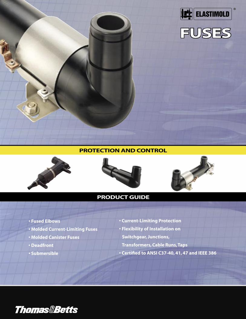
product guide protection and control - … & betts’ protection and control products provide...
TRANSCRIPT
FUSES
PROTECTION AND CONTROL
PRODUCT GUIDE
®
• Fused Elbows
• Molded Current-Limiting Fuses
• Molded Canister Fuses
• Deadfront
• Submersible
• Current-Limiting Protection
• Flexibility of Installation on
Switchgear, Junctions,
Transformers, Cable Runs, Taps
• Certified to ANSI C37-40, 41, 47 and IEEE 386
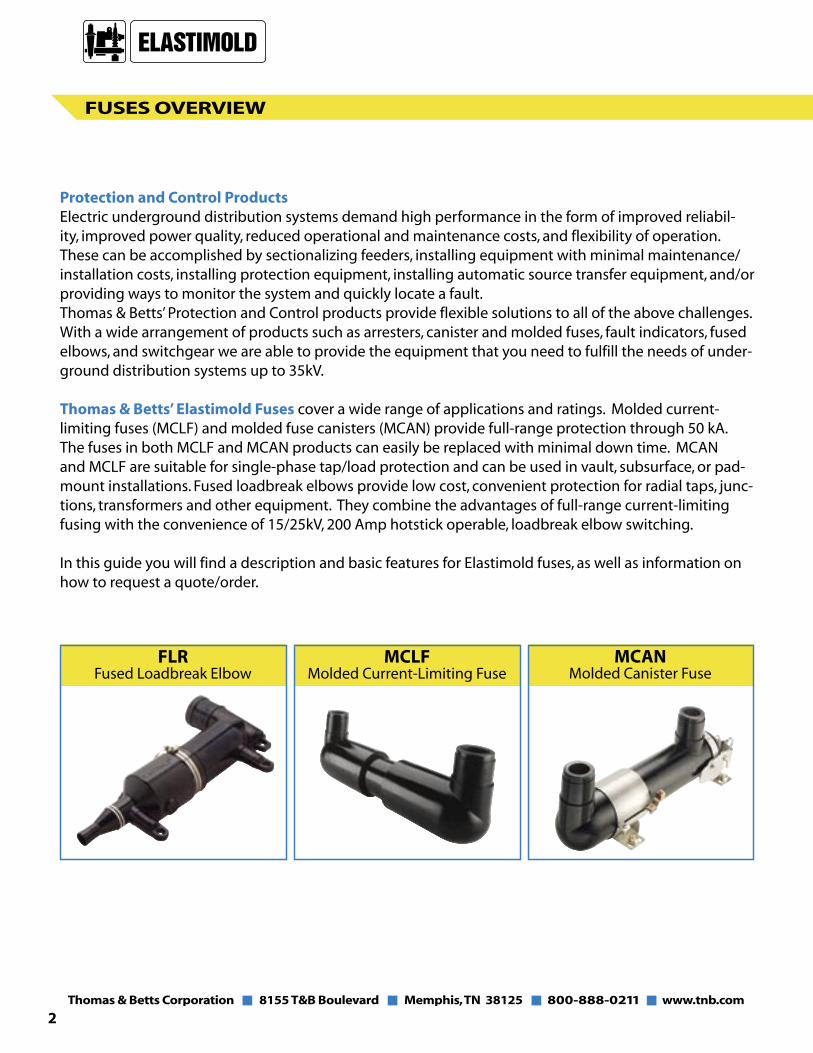
Protection and Control ProductsElectric underground distribution systems demand high performance in the form of improved reliabil-ity, improved power quality, reduced operational and maintenance costs, and flexibility of operation. These can be accomplished by sectionalizing feeders, installing equipment with minimal maintenance/installation costs, installing protection equipment, installing automatic source transfer equipment, and/or providing ways to monitor the system and quickly locate a fault. Thomas & Betts’ Protection and Control products provide flexible solutions to all of the above challenges. With a wide arrangement of products such as arresters, canister and molded fuses, fault indicators, fused elbows, and switchgear we are able to provide the equipment that you need to fulfill the needs of under-ground distribution systems up to 35kV.
Thomas & Betts’ Elastimold Fuses cover a wide range of applications and ratings. Molded current-limiting fuses (MCLF) and molded fuse canisters (MCAN) provide full-range protection through 50 kA. The fuses in both MCLF and MCAN products can easily be replaced with minimal down time. MCAN and MCLF are suitable for single-phase tap/load protection and can be used in vault, subsurface, or pad-mount installations. Fused loadbreak elbows provide low cost, convenient protection for radial taps, junc-tions, transformers and other equipment. They combine the advantages of full-range current-limiting fusing with the convenience of 15/25kV, 200 Amp hotstick operable, loadbreak elbow switching.
In this guide you will find a description and basic features for Elastimold fuses, as well as information on how to request a quote/order.
FUSES OVERVIEW
2
FLRFused Loadbreak Elbow
MCLFMolded Current-Limiting Fuse
MCANMolded Canister Fuse

FUSED LOADBREAK ELBOW
3
FUSED ELBOWS
Elastimold Fused Elbows combine the advantages of Full-Range Current-Limiting Fusing with the convenience of 15/25kV hot stick operable, loadbreak elbow switching.
FEATURE BENEFIT / DESCRIPTIONn EPDM Molded Rubber Deadfront n Fully sealed and submersible
Construction n Insulate, shield and eliminate exposed live parts
n Split Center Section n Easy fuse replacement
n Built-in Voltage test points or n Quick and convenient blown fuse access ports indication
n Full-range current-limiting n Facilitates fusing of light duty fusing with 50kA interrupting underground distribution systems capability including sub-loops, radial taps,
n Rated 5kV Ungrounded to 25kV junctions, transformers, and other Grounded Wye equipment
n 15/25kV hot stick operable, loadbreak elbow switching
This is the fastest, most cost effective way to improve the distribution system’s reliability without adding a separate piece of switchgear or replacing existing sectionalizing cabinets. Simply replace existing 200 Amp tap elbows with Elastimold Fused Elbows to protect light duty underground distribution systems including sub-loops, and radial taps. The following example shows how much improvement in reliability is achieved by adding protection to a tap.
Breaker Locks Out
Junction Cabinet
3-WayUnit
Loop system without tap protection: A fault on the tap will lock out the substation breaker and generate an outage for all customers to the open point.
B1 B2
S3I4B2
NC NC
NC
NO
Breaker Closed
Junction Cabinet
3-WayUnit
Loop system with tap protection: A fault on the tap will be isolated by the FUSED ELBOW(s). This reduces the number of customers affected by the outage, thus improving the system’s System Average Interruption Frequency Index (SAIFI).
B1 B2
S3I4B2
NC NC
NC
NO
FAULT
FUSE ISOLATES FAULT

FUSED LOADBREAK ELBOW
4
CERTIFIED TESTS & PERFORMANCE
Elastimold fused elbows have been designed and tested per applicable portions of IEEE, ANSI, and other industry standards including:
n ANSI C37.40 Standard for Current-Limiting Fuse Service Conditions.
n ANSI C37.41 Standard for Current-Limiting Fuse Design & Testing.
n ANSI C37.47 Standard for Current-Limiting Fuse Ratings & Specifications.
n IEEE 386 Standard for Separable Connectors.
RATINGS
System Voltage Class (kV) 15 25 25/28* Nominal Fuse Voltage (kV) 8.3 15.5 17.2 Rated Maximum Fuse Voltage (kV) 10 15.5 17.2 Frequency (Hz) 50-60 50-60 50-60 BIL Impulse Withstand (kV) 95 125 140 One Minute AC Withstand (kV) 34 40 45 Fifteen Minute DC Withstand (kV) 53 78 78 Corona Extinction (kV) 11 19 21.5 Symmetrical Interrupting Capability (Amp) 50,000 50,000
50,000
Current Rating (Amp) 6-45 6-20 6-45
APPLICATION INFORMATION
Construction: Submersible, non-venting, deadfront, corrosion resistant.
Ambient Temperature Range: – 30 to +65 degrees centigrade.
* The 28kV rated fuse requires at least 75% grounded load.
1. Probe
2. Upper Elbow Half
3. Probe Lug
4. Fuse
5. Crimp Lug
7. Lower Elbow Half
6. Hose Clamp

FUSED LOADBREAK ELBOW
5
Notes:
1. Designs have a 50,000 Amps rms. Symmetrical Rating.
2. Fuses have a Rated Maximum Application Temperature of 65ºC (RMAT is the maximum temperature of the air, in contact with the elbow housing, at which they have been shown to be suitable for use).
3. Tabulated Maximum Total I2t values are for currents of 50,000 amperes at the nominal voltage of the fuse. Values for 8.3kV fuses at 10kV are approximately 30% higher. Values for 17.2kV fuses at 15.5kV are approximately 20% lower.
4. Maximum total I2t values are reduced for currents below 50,000 A. For example, at 10,000 A, maximum total I2t values are approximately 15% less than the published values.
5. Peak arc voltages quoted are for 50,000 A currents at the rated maximum voltage listed. Reduced currents and voltages will reduce the peak arc voltage. Consult the factory for further information.
6. Maximum continuous currents at ambient temperatures other than those listed may be determined by derating the fuses by 0.2% per degree C over 25º C. For example: At 40º C the derating would be 15 x .2 = 3%, making the maximum continuous current of a 17.2kV 25A fuse 31.5 x .97 = 30.5A.
7. Time-current characteristic curves are published at 25ºC. Reduction in the long time melting current of the fuses (approximately one hour and longer) due to higher ambient temperatures is the same as described above for “maximum continuous currents”.
ELECTRICAL CHARACTERISTICS OF EFX-ELBOW FUSES
Nominal Fuse Current Fuse Rated Maximum Peak Arc Minimum Maximum Voltage Rating Model Maximum Continuous Current Voltage Melt l2t Total l2t Rating Number Voltage (2) (6) (kV) (3) (4) (kV) (A) (kV) 25o C 40oC 65oC (5) (AMP2-SEC) (AMP2-SEC) 8.3 6 EFX083006-E 10.0 9.5 9.0 8.5 32 620 2,700 8.3 8 EFX083008-E 10.0 11.5 11.0 10.5 28 800 4,000 8.3 10 EFX083010-E 10.0 14.0 13.5 13.0 28 800 4,000 8.3 12 EFX083012-E 10.0 19.0 18.5 17.5 26 920 8,000 8.3 18 EFX083018-E 10.0 21.0 20.0 19.0 26 1,310 9,500 8.3 20 EFX083020-E 10.0 26.0 25.0 24.0 26 1,620 11,000 8.3 25 EFX083025-E 10.0 34.0 33.0 31.0 26 3,660 22,000 8.3 30 EFX083030-E 10.0 37.5 36.5 34.5 26 5,250 30,000 8.3 40 EFX083040-E 10.0 43.0 42.0 40.0 26 8,700 50,000 8.3 45 EFX083045-E 10.0 49.0 47.0 45.0 26 12,800 70,000 15.5 6 EFX155006-E 15.5 8.5 8.0 7.7 52 620 3,000 15.5 8 EFX155008-E 15.5 10.5 10.0 9.5 40 800 4,300 15.5 10 EFX155010-E 15.5 13.0 12.5 12.0 40 800 4,300 15.5 12 EFX155012-E 15.5 16.0 15.5 15.0 38 920 8,000 15.5 18 EFX155018-E 15.5 20.0 19.5 18.5 38 1,620 13,000 15.5 20 EFX155020-E 15.5 23.5 22.5 21.5 38 2,200 16,500 17.2 6 EFX172006-E 17.2 9.5 9.0 8.5 54 620 3,250 17.2 8 EFX172008-E 17.2 11.5 11.0 10.5 46 800 4,600 17.2 10 EFX172010-E 17.2 14.0 13.5 13.0 46 800 4,600 17.2 12 EFX172012-E 17.2 18.0 17.5 16.5 43 920 8,500 17.2 18 EFX172018-E 17.2 20.0 19.5 18.5 45 1,310 10,000 17.2 20 EFX172020-E 17.2 24.0 23.0 22.0 45 1,620 12,500 17.2 25 EFX172025-E 17.2 31.5 30.5 29.0 45 3,660 27,500 17.2 30 EFX172030-E 17.2 35.5 34.5 32.5 45 5,250 37,500 17.2 40 EFX172040-E 17.2 41.0 40.0 38.0 45 8,700 62,500 17.2 45 EFX172045-E 17.2 46.0 45.0 42.5 45 12,800 87,500
SystemVoltage
Class(kV)
15
25
25/28
Nominal FuseVoltage Rating
168 8.3kV 274 15.5kV 274 17.2kV
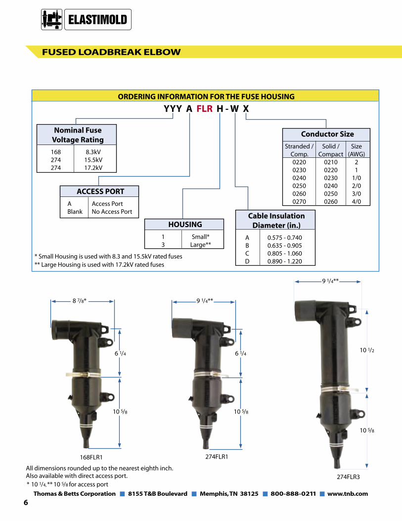
ORDERING INFORMATION FOR THE FUSE HOUSING
YYY A FLR H - W X
ACCESS PORT
A Access Port Blank No Access Port
HOUSING
1 Small* 3 Large**
Cable InsulationDiameter (in.)
A 0.575 - 0.740 B 0.635 - 0.905 C 0.805 - 1.060 D 0.890 - 1.220
Conductor Size
Stranded / Solid / Size Comp. Compact (AWG) 0220 0210 2 0230 0220 1 0240 0230 1/0 0250 0240 2/0 0260 0250 3/0 0270 0260 4/0
* Small Housing is used with 8.3 and 15.5kV rated fuses** Large Housing is used with 17.2kV rated fuses
FUSED LOADBREAK ELBOW
6
Also available with direct access port. All dimensions rounded up to the nearest eighth inch.
* 10 1/4, ** 10 5/8 for access port
168FLR1 274FLR1
8 7/8*
274FLR3
6 1/4
10 5/8
9 1/4**
6 1/4
10 5/8
9 1/4**
10 1/2
10 5/8

FUSED LOADBREAK ELBOW
7
ORDERING INFORMATION FOR THE FULL-RANGE CURRENT-LIMITING FUSE
EFX YYY AAA - E
Voltage Rating
083 8.3kV 155 15.5kV 172 17.2kV
Amperage Rating (A)*
006 6 008 8 010 10 012 12 018 18 020 20 025 25 030 30 040 40 045 45
* 8.3 / 17.2kV rated fuses are available in all Amp ratings listed15.5kV fuse sizes are available between 6-20 Amp
9 1/4
13 1/2
All dimensions rounded up to the nearest eighth inch.
8.3/15.5 kV Fuse
17.2 kV Fuse
2 1/4
2 1/4
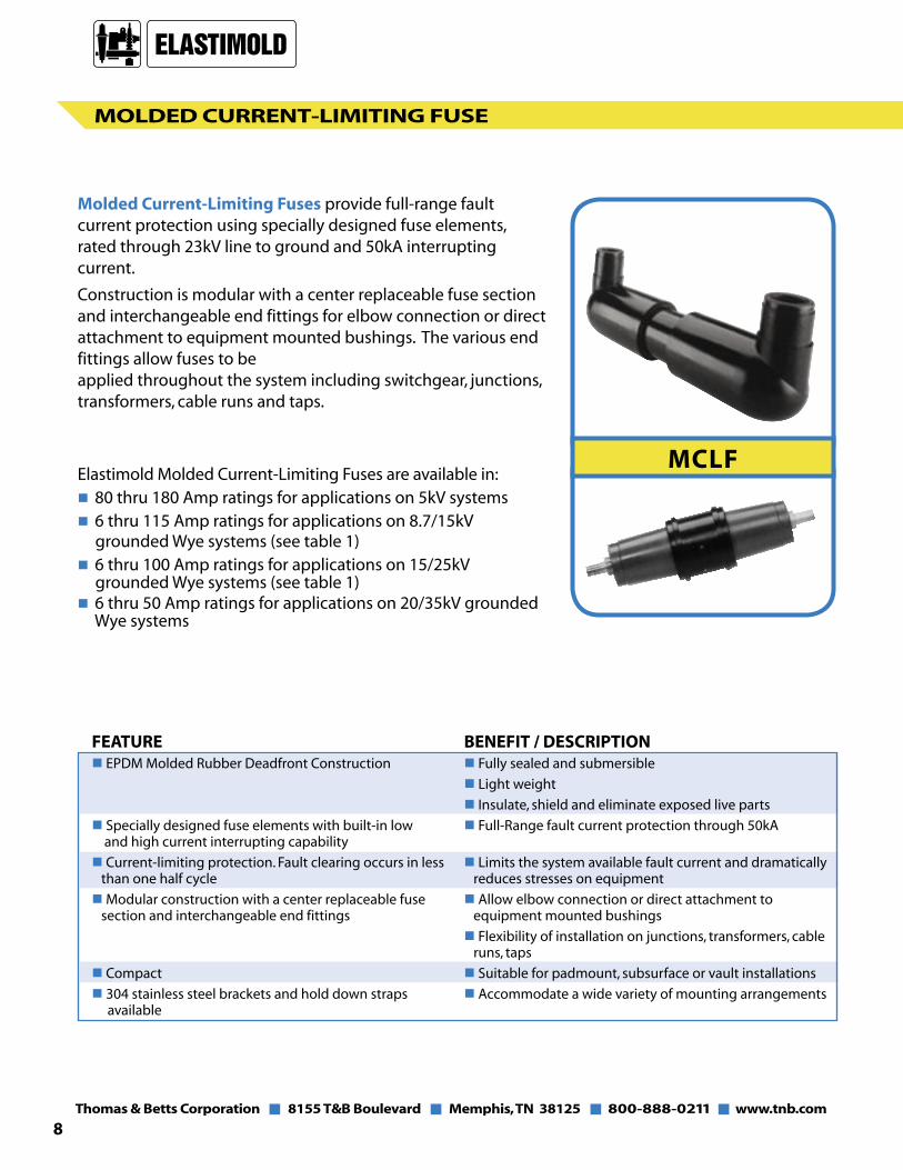
MOLDED CURRENT-LIMITING FUSE
Molded Current-Limiting Fuses provide full-range fault current protection using specially designed fuse elements, rated through 23kV line to ground and 50kA interrupting current.
Construction is modular with a center replaceable fuse section and interchangeable end fittings for elbow connection or direct attachment to equipment mounted bushings. The various end fittings allow fuses to be applied throughout the system including switchgear, junctions, transformers, cable runs and taps.
Elastimold Molded Current-Limiting Fuses are available in: n 80 thru 180 Amp ratings for applications on 5kV systemsn 6 thru 115 Amp ratings for applications on 8.7/15kV grounded Wye systems (see table 1)n 6 thru 100 Amp ratings for applications on 15/25kV grounded Wye systems (see table 1)n 6 thru 50 Amp ratings for applications on 20/35kV grounded Wye systems
8
FEATURE BENEFIT / DESCRIPTIONn EPDM Molded Rubber Deadfront Construction n Fully sealed and submersible
n Light weight
n Insulate, shield and eliminate exposed live parts
n Specially designed fuse elements with built-in low n Full-Range fault current protection through 50kA and high current interrupting capability
n Current-limiting protection. Fault clearing occurs in less n Limits the system available fault current and dramatically than one half cycle reduces stresses on equipment
n Modular construction with a center replaceable fuse n Allow elbow connection or direct attachment to section and interchangeable end fittings equipment mounted bushings
n Flexibility of installation on junctions, transformers, cable runs, taps
n Compact n Suitable for padmount, subsurface or vault installations
n 304 stainless steel brackets and hold down straps n Accommodate a wide variety of mounting arrangements available
MCLF

MOLDED CURRENT-LIMITING FUSE
CERTIFIED TESTS & PERFORMANCE
Elastimold Molded Current-Limiting Fuses have been designed and tested per applicable portions of IEEE, ANSI, NEMA and other industry standards including:
n ANSI C37.40 Standard for Current-Limiting Fuse Service Conditions.
n ANSI C37.41 Standard for Current-Limiting Fuse Design and Testing.
n ANSI C37.47 Standard for Current-Limiting Fuse Ratings and Specifications.
n ANSI/IEEE 386 Standard for Separable Connectors & Bushing Interfaces.
Replaceable Molded Rubber Current-Limiting Fuse
Interchangeable Molded Rubber
End Fittings
Assembled Fuse Unit
Assembled Fuse Unit with Optional Wall Mounting Bracket
9
RATINGS System Voltage Class (kV) 5 15 25/28 35
Rated Maximum Fuse Voltage (kV) 5.5 10* 17.2* 23
Frequency (Hz) 50/60 50/60 50/60 50/60
BIL Impulse Withstand (kV) 60 95 125/140 150
One Minute AC Withstand (kV) 34 34 40/45 50
Fifteen Minute DC Withstand (kV) 53 53 78 103
Corona Extinction (kV) 11 11 19/21.5 26
Symmetrical Interrupting Capability (Amp) 50,000 50,000 50,000 50,000
Current Rating (Amp) 80-180 6-115 6-100 6-50
APPLICATION INFORMATION
Construction: Submersible, non-venting, deadfront, corrosion resistant.
Ambient Temperature Range: -30 to +65 degrees centigrade for 6-50 Amp fuses;
-30 to +40 degrees centigrade for >50 Amp fuses.
* These maximum design voltages apply to fuses rated between 6-50 Amp; for fuses with higher amperage rating the
maximum design voltage is 8.3 kV for 15 kV systems and 15.5 kV for 25/28 kV systems.

FUSE ORDERING INFORMATION
To completely specify and order a Molded Current-Limiting Fuse:
1. Select the Fuse Catalog Number from Table 1 based on the amperage and system voltage class. This table is also used to order spare or replacement fuses.
2. From Table 2 select a Model Number based on the required fuse end fittings. If end fittings are to be ordered and shipped separately from the fuse, use Table 4.
3. Select Mounting Options (if required) from Table 3.
Example:To order a fuse for application in a 25kV system, rated 50 Amp with factory assembled 200 Amp Deepwell end fittings and no mounting provision, specify: Catalog No. M25CLF50-22
Mounting Provision (See Table 3)
MOLDED Current-limiting FUSE
Approx. Weight 30 lbs.
10
TABLE 2 – FUSE END FITTING ARRANGEMENTS
Outline Model Number Description
22 200 Amp Deepwell on both ends.
TABLE 1 – FUSE CATALOG NUMBERS
Ampere Rating 5kV Catalog No. 8.7/15kV GRD-Y* 15/25kV GRD-Y† 20/35kV GRD-Y Catalog No. Catalog No. Catalog No. 10 – M15CLF010 M25CLF010 M35CLF010 20 – M15CLF020 M25CLF020 M35CLF020 30 – M15CLF030 M25CLF030 M35CLF030 40 – M15CLF040 M25CLF040 M35CLF040 50 – M15CLF050 M25CLF050 M35CLF050 65 – M15CLF065 M25CLF065 – 80 M05CLF080 M15CLF080 M25CLF080 – 100 M05CLF100 M15CLF100 M25CLF100 – 125 M05CLF125 M15CLF115 – – 150 M05CLF150 – – – 185 M05CLF180 – – – Note: Fuses rated 6, 8, 12, 18 and 25 Amps are also available by special request. Contact Factory for additional information. Grounded Y systems must have enough grounded load to prevent the recovery voltage from exceeding the fuse’s maximum voltage. * For 65 Amp and higher, the fuses have a rated maximum voltage of 8.3 kV † For 65 Amp and higher, the fuses have a rated maximum voltage of 15.5 kV

MOLDED Current-limiting FUSE
Approx. Weight 35 lbs.
Approx. Weight 40 lbs.
Approx. Weight 30 lbs.
Approx. Weight 30 lbs.
Approx. Weight 30 lbs.
11
TABLE 2 – FUSE END FITTING ARRANGEMENTS (Cont’d)
Outline Model Number Description
222 200 Amp Deepwell on one end and two 200 Amp Deepwells on the other end
2222 Two 200 Amp Deepwells on both ends.
66 600 Amp Bushings on both ends.
6E2
600 Amp Elbow Connector for attachment to equipment mounted 600 Amp Bushing on one end and a 200 AmpDeepwell on the other end.
This arrangement is not available at 20/35 kV
6E6
600 Amp Elbow Connector for attachment to equipment mounted 600 Amp Bushing on one end and a 600 Amp
Bushing on the other end.
This arrangement is not available at 20/35 kV
Note: Other models are available such as 26.

MOLDED CURRENT-LIMITING FUSE
12
TABLE 4 – END FITTING CATALOG NUMBERS
Use this table only if end fittings are to be ordered and shipped separately from the fuse. Use Table 2 for assembled units.
Catalog Description System IEEE 386-1995Number Voltage Class Interface Reference
EF2 200 Amp Deepwell End Fitting (kV) 5, 15, 25 & 35 Figure 3EF22 Double 200 Amp Deepwell End 5, 15, 25 & 35 Figure 3
Fitting (kV)EF6 600 Amp Bushing End Fitting (kV) 5, 15, 25 & 35 Figure 11EF6E 600 Amp Elbow Connector 5, 15 & 25 Figure 11
End Fitting (kV)
Note: EF6E is equipped with a standard thru hole spade lug (Type 03700).
OPTIONAL MOUNTING BRACKET WITH ADJUSTABLE PARKING STANDS FOR VERTICAL MOUNTING AND FUSE HOLD DOWN STRAPS
Approx. Weight 8 lbs.
OPTIONAL UNIVERSAL MOUNTING TILT ADAPTERS
TABLE 3 – FUSE MOUNTING OPTIONS
Option Number Description HDS Bolted Style Hold Down Strap (Qty: 1 required per end fitting) QRS Quick Release Style Hold Down Strap (Qty: 1 required per end fitting) WMB Wall Mounting Bracket with Parking Stands and Bolted Style Hold Down Straps (HDS) WMBQ Wall Mounting Bracket with Parking Stands and Quick Release Style Hold Down Straps (QRS) SMB Support Mounting Bracket for use with Models 6E2 or 6E6 end fitting arrangements. Includes Bolted Style Hold Down Strap (HDS). TMA-EM Tilt Mounting Adapter. Bolts to bottom of Wall Mounting Bracket WMB or WMBQ to allow up to 60º angle mounting. (Qty 2 required per installation)
Note: The Option number should be added as a suffix to the MCLF catalog number.

MOLDED CURRENT-LIMITING FUSE
(Assembly/Disassembly Tool)
13
ELECTRICAL CHARACTERISTICS OF ENCAPSULATED FUSES USED IN MCLF
Nominal Fuse Current Fuse Rated Maximum Peak Arc Minimum Maximum Voltage Rating Model Maximum Continuous Current Voltage Melt l2t Total l2t Rating Number Voltage (kV) (2) (kV) (A) (kV) 25o C 40oC (3) (AMP2-SEC) (AMP2-SEC) 80 M05CLF080 5.5 86 84 15.0 22,100 110,000 100 M05CLF100 5.5 108 105 15.0 56,700 280,000 5.5 125 M05CLF125 5.5 137 133 15.0 109,200 530,000 150 M05CLF150 5.5 159 154 15.0 176,000 860,000 180 M05CLF180 5.5 185 180 15.0 259,000 1,270,000 10 M15CLF010 10.0 14 13 28 800 4,000 20 M15CLF020 10.0 23 22 26 1,620 11,000 30 M15CLF030 10.0 35 33 26 5,250 30,000 40 M15CLF040 10.0 43 41 26 8,700 50,000 8.3 50 M15CLF050 10.0 50 47 26 12,800 70,000 65 M15CLF065 8.3 73.0 71.0 25 25,200 100,000 80 M15CLF080 8.3 87.0 84.0 25 47,000 185,000 100 M15CLF100 8.3 106.0 103.0 25 78,300 330,000 115 M15CLF115 8.3 120.0 116.0 25 115,150 480,000 10 M25CLF010 17.2 14 13 46 800 3,700 20 M25CLF020 17.2 23 22 45 1,620 10,000 30 M25CLF030 17.2 35 33 45 5,250 30,000
15.5 40 M25CLF040 17.2 43 41 45 8,700 50,000
50 M25CLF050 17.2 47 45 45 12,800 70,000 65 M25CLF065 15.5 68.0 66.0 40 25,200 110,000 80 M25CLF080 15.5 88.0 85.0 40 54,400 255,000 100 M25CLF100 15.5 100.0 100.0 40 80,000 380,000 10 M35CLF010 23.0 14 13 61 800 4,800 20 M35CLF020 23.0 23 22 60 1,620 13,000 23.0 30 M35CLF030 23.0 35 33 60 5,250 38,000 40 M35CLF040 23.0 41 40 60 8,700 61,000 50 M35CLF050 23.0 47 46 60 12,800 82,000Notes:1. Designs have a 50,000 Amps rms. Symmetrical Rating.2. Maximum total l2t values are reduced for currents below 50,00A. For example, at 10,000A, l2t values are approximately 15% less than the published values.3. Peak arc voltages quoted are for 50,000A currents at the rated maximum voltage listed. Reduced currents and voltages will reduce the peak arc voltage. Consult the factory for further information.
OTHER OPTIONS
Catalog Number Description
MCLF-ADT Hex Wrench for set screw removal and replacement when disassembling end fittings. Supplied as standard with replacement fuses.

Cable ConnectionBushings or Wells
Molded EPDM Rubber Insulation and Shielding
EFX Full-Range Current-Limiting Fuse
End Plug with Eye
Mounting FeetLatching Lever
MOLDED FUSE CANISTER
MCAN
14
FEATURE BENEFIT / DESCRIPTIONn EPDM Molded Rubber Deadfront Construction n Fully sealed and submersible
n Insulate, shield and eliminate exposed live parts
n Compact n Suitable for padmount, subsurface or vault installations
n Modular construction n Allow elbow connection or direct attachment to equipment mounted bushings
n Neon voltage indicators (V2) attached to elbow test points, allow quick and convenient blown fuse indication
n Various end fittings and bushings n Flexibility of installation on switchgear, junctions, transformers, cable runs, taps
n Replaceable fuse section n Ease of fuse replacement without full removal from installation
n Current-limiting protection. Fault clearing occurs in n Limits the system available fault current and dramatically less than one half cycle reduces stresses on equipment
n 304 series stainless steel mounting brackets, and wall n Accommodate a wide variety of mounting arrangements mounted parking stands available
The MCAN Molded Fuse Canister is a compact, lightweight EPDM Molded Rubber Fuse Enclosure Package. MCAN fuse canisters are maintenance-free, completely sealed and submersible. Designs are deadfront using molded rubber to insulate, shield and eliminate exposed live parts. Units are ideally suited for padmount, subsurface or vault applications, for systems through 25kV.
MCAN uses Elastimold EFX full-range current-limiting fuses capable of interrupting up to 50kA.
The MCAN Molded Fuse Canister will accommodate and has been thoroughly tested with Elastimold EFX and Hi-Tech Trans-Guard FX fuses. Please contact Elastimold for other non-gassing, current-limiting fuses that have been qualified by Elastimold for use in the MCAN Canister.

MOLDED FUSE CANISTER
15
Elastimold EFX Current-Limiting Fuses are available in:n 3 thru 50* Amp, 8.3kVn 3 thru 50* Amp, 15.5kVn 6 thru 50* Amp, 23.0kV
EFX Fuses provide the benefits of current-limiting protection with fault clearing occurring in less than one half cycle, thereby limiting the let-through fault current and dramatically reducing stresses on equipment. The EFX full-range current-limiting fuse provides both overload and fault current protection for distribution equipment in a single fuse body. As a full-range fuse, it is capable of interrupting any continuous current between the minimum current that can cause melting of the elements and its rated maximum interrupting current (50,000 amps).
The fuses are capable of interrupting in elevated ambient temperature, which is 140° C for the 2.25” fuse. The recommended rated maximum application temperature (RMAT) for the MCAN molded fuse canister is 65° C. The EFX fuse is hermetically sealed and thus discharges no gasses during fuse operation.
Tin Plated Bronze Caps
Low Current Interruption Element (Includes Patent Damage Sensor)
Compacted Quartz Sand
Epoxy Joint
High Current Interruption Element
EFX Current-Limiting Fuse
➧➧
EFX Fuse design features include:n Patented Damage Sensor® designed to significantly reduce the risk of fuse failure should the fuse be subject to an element damaging current surge.n Hermetically sealed construction ensures that no gasses escape from the fuse during current interruption. All EFX fuses are helium mass spectrometer leak tested to ensure sealing system integrity.n Rugged machined brass end caps used for greater ferrule strength resulting in less distortion and more secure fuse attachment in dry-well canisters.
* Rating may be reduced when used in a canister. Damage Sensor is patented technology of Hi-Tech Fuses, Inc.

MOLDED FUSE CANISTER
CERTIFIED TESTS & PERFORMANCEElastimold Molded Fuse Canisters and EFX fuses have been designed and tested per applicable portions of IEEE, ANSI, NEMA and other industry standards including:
n ANSI C37.40 Standard for Current-Limiting Fuse Service Conditions.
n ANSI C37.41 Standard for Current-Limiting Fuse Design & Testing.
n ANSI C37.47 Standard for Current-Limiting Fuse Ratings & Specifications.
n ANSI/IEEE 386 Standard for Separable Connectors & Bushing Interfaces.
* Without Fuse ++3 amp fuse was tested @ 44kA
200 Amp Bushing Well
200 Amp Bushing Well
600 Amp Bushing
600 Amp Elbow
ORDERING INFORMATIONTo specify and order an EFX fuse and an MCAN fuse canister:
1. Select the Fuse Catalog Number from Table 5 based on the amperage and “Rated Max Voltage (kV)” column. Note the fuses current carrying ability is reduced when used in a canister.
2. Based on selected fuse, select canister from the “Minimum Canister Required” column of Table 5. See Table 6 for additional MCAN Fuse Canister information including required bushing or elbow connecting interface. (Make sure that the Canister Mounting Code and Diameter Code match the Fuse Mounting Code and Diameter Code).
3. Select Options and accessories (if required) from Table 7.
Example:To order a 15.5kV, 50 Amp fuse, a fuse canister for this fuse with 200 Amp bushing well and no options or accessories specify: Catalog No. EFX155050 and MCAN-5B25-22.
16
MCAN FUSE CODING SYSTEM Mounting Code Max. Fuse Overall Length Diameter Code Max. Fuse Overall Diameter
4 10.11” B 2.25”
5 14.69” B 2.25”
6 17.51” B 2.25”
FUSE CANISTER RATINGSSystem Voltage Class (kV) 15 25/28 35
Maximum Line to Ground Voltage (kV) 10.0 17.2 23
Frequency (Hz) 50/60 50/60 50/60
BIL Impulse Withstand (kV) 95 125/140 150
One Minute AC Withstand (kV) 34 40/45 50
Fifteen Minute DC Withstand (kV) 53 78 103
Corona Extinction (kV) 11 19/21.5 26
Maximum Continuous Current (Amps) 200* 200* 200*
Momentary Current (kA) 10* 10* 10*
Construction: Submersible, corrosion resistant, fully shielded
Ambient Temperature Range: -30 to 65° C
FUSE RATINGSNominal Voltage Rating (kV) 8.3 15.5 23.0
Rated Maximum Voltage (kV) 10.0 17.2 23.0
Frequency (Hz) 50/60 50/60 50/60
Current Rating (Amp) 3-50+ 3-50+ 6-50+
Rated Maximum InterruptingCurrent (Sym. Amperes)
50,000 50,000++ 50,000
Ambient Temperature Range: –30 to 140° C for the 2.25” diameter fuse
Note: Lower Mounting Codes (shorter) fuses many be applied in canisters of higher Mounting Codes by using an adapter. See Mounting Code Adapters table 7.

“A”
“B”
“D”“C”
MOLDED FUSE CANISTER
All dimensions are in inchesFor 5kV systems, use the 8.3 kV rated fuses
17
TABLE 5 – EFX FUSE ORDERING INFORMATION, WEIGHTS AND DIMENSIONS
Nominal Fuse Rated Current Voltage Fuse Max Overall Overall Contact Body Minimum Fuse Rating Rating Catalog Voltage Mtg. Dia. Dia. Length Length Length Canister Wt.(Amps) (kV) Number (kV) Code Code (A) (B) (C) (D) Required (lbs)
3 EFX083003
6 EFX083006
8 EFX083008
10 EFX083010
12 EFX083012 MCAN-4B15-22
18 8.3 EFX083018 10.0 4 B 2.25 10.00 1.02 7.96 MCAN-4B15-66 3.00
20 EFX083020 MCAN-4B15-6E2
25 EFX083025 MCAN-4B15-6E6
30 EFX083030
40 EFX083040
50 EFX083050
3 EFX155003
6 EFX155006
8 EFX155008
10 EFX155010
12 EFX155012 MCAN-5B25-22
18 15.5 EFX155018 17.2 5 B 2.25 14.31 1.02 12.27 MCAN-5B25-66 4.25
20 EFX155020 MCAN-5B25-6E2
25 EFX155025 MCAN-5B25-6E6
30 EFX155030
40 EFX155040
50 EFX155050
6 EFX230006
8 EFX230008
10 EFX230010
12 EFX230012
18 EFX230018
20 23.0 EFX230020 23.0 6 B 2.25 17.12 1.02 15.09 MCAN-6B25-66 4.75
25 EFX230025
30 EFX230030
40 EFX230040
50 EFX230050

MOLDED FUSE CANISTER
18
TABLE 6 – WEIGHTS (LBS.) AND DIMENSIONS (IN.)
FIGURE CATALOG NUMBER (A) (B) (C)
MCAN-4B15-22 21.49 10.06 10.91 19
MCAN-5B25-22 25.80 14.37 15.22 21
MCAN-6B25-22 28.68 17.25 18.10 22
MCAN-4B15-66 21.49 10.06 10.91 21
MCAN-5B25-66 25.80 14.37 15.22 23
MCAN-6B25-66 28.68 17.25 18.10 24
Approx.Weight
(lbs)
End Bushing*
MainBushing*
200 AmpBushing
Well
200 AmpBushing
Well
600 AmpBushing
600 AmpBushing
* Other bushing combinations including - 26 and 62 are also available.

MOLDED FUSE CANISTER
19
TABLE 6 – WEIGHTS (LBS.) AND DIMENSIONS (IN.)
FIGURE CATALOG NUMBER (A) (B) (C)
MCAN-4B15-6E2 23.90 10.06 12.91 20
MCAN-5B25-6E2 28.21 14.37 17.22 22
MCAN-6B25-6E2 31.08 17.25 20.09 23
MCAN-4B15-6E6 23.90 10.06 12.91 20
MCAN-5B25-6E6 28.21 14.37 17.22 22
MCAN-6B25-6E6 31.08 17.25 20.09 23
Approx.Weight
(lbs)
End Bushing*
MainBushing*
600 AmpElbow
Connector
200 AmpBushing
Well
600 AmpElbow
Connector
600 AmpBushing
* Other bushing combinations including - 26 and 62 are also available.

MOLDED FUSE CANISTER
TABLE 7 – MCAN MOLDED FUSE CANISTER OPTIONS AND ACCESSORIES
160WMPS
20
Voltage IndicatorsNeon voltage indicators mounted to the test point provision on the MCAN elbow connectors provide quick and convenient indication of an energized circuit. The voltage indicator will illuminate with a flashing neon light when the elbow connector is energized. If the fuse opens/clears the neon lights on the load side elbows will stop flashing, indicating that the fuse has blown. Refer to operation instructions for additional detail.
Mounting Code AdaptersA mounting code adapter is used to extend the fuse end cap ferrule so that a shorter fuse may be used in a longer code canister. Example: A code 4B size fuse can be used in a code 5B Canister with an MCAN-4-5 adapter.
Parking StandsParking stands can be mounted adjacent to MCAN Fuse Canister allowing attachment of additional accessories to ground, isolate and test the elbow cable connectors.
Switchgear AssembliesElastimold multi-point junctions shown in catalog C-MPJ can be utilized to create custom switchgear lineups consisting of MVS switches, MVI fault interrupters, MCLF current-limiting fuses, MCAN fuse canisters, fused elbows, elbow arresters and other molded products. The junction allows easy assembly and interconnection of components into fully shielded, submersible, compact arrangements.
Catalog Number Description
MCAN-4-5 Code 4B size fuse to a code 5B Canister
MCAN-4-6 Code 4B size fuse to code 6B Canister
MCAN-5-6 Code 5B size fuse to a code 6B Canister
Catalog Number Description
V2 Capacitive Test Point, Voltage Indicator
Suffix Number Description
-PS Parking Stand between bushings
Catalog Number Description
160WMPS Wall Mount Parking Stand

MOLDED FUSE CANISTER
21
Nominal Fuse Current Fuse Rated Maximum Continuous Maximum Continuous Peak Arc Minimum Maximum Voltage Rating Model Maximum Current (In Air) Current (In MCAN) Voltage Melt I2T Total I2T Rating Number Voltage (6) (6) (kV) (3) (4) (kV) (A) (kV) 25ø C 40øC 65øC 25øC 40øC 65øC (5) (Amp2 Sec) (Amp2 Sec)
3 EFX083003 5.0 4.9 4.6 4.3 4.2 3.9 30 100 350 6 EFX083006 11.0 10.5 10.0 9.5 9.0 8.5 32 620 2,700 8 EFX083008 13.5 13.0 12.5 11.5 11.0 10.5 28 800 4,000 10 EFX083010 16.0 15.5 15.0 13.5 13.0 12.5 28 800 4,000 12 EFX083012 20.5 19.5 19.0 17.5 17.0 16.0 26 920 8,000 8.3 18 EFX083018 10.0 23.5 22.5 21.5 19.5 19.0 18.0 26 1,310 9,500 20 EFX083020 27.5 26.5 25.0 24.0 23.0 21.5 26 1,620 11,000 25 EFX083025 37.0 35.5 34.0 29.5 28.5 27.0 26 3,660 22,000 30 EFX083030 41.0 39.5 38.0 34.0 33.0 31.0 26 5,250 30,000 40 EFX083040 50.0 48.5 46.0 40.0 39.0 36.5 26 8,700 50,000 50 EFX083050 57.0 55.0 52.5 45.5 44.0 42.0 26 12,800 70,000 3 EFX155003 5.0 4.9 4.6 4.3 4.2 3.9 51 100 510 6 EFX155006 11.0 10.5 10.0 9.5 9.0 8.5 54 620 2,600 8 EFX155008 13.5 13.0 12.5 11.5 11.0 10.5 46 800 3,700 10 EFX155010 16.0 15.5 15.0 13.5 13.0 12.5 46 800 3,700 12 EFX155012 20.5 19.5 19.0 17.5 17.0 16.0 43 920 6,500 15.5 18 EFX155018 17.2 23.5 22.5 21.5 19.5 19.0 18.0 45 1,310 8,000 20 EFX155020 27.5 26.5 25.0 24.0 23.0 21.5 45 1,620 10,000 25 EFX155025 37.0 35.5 34.0 29.5 28.5 27.0 45 3,660 22,000 30 EFX155030 41.0 39.5 38.0 34.0 33.0 31.0 45 5,250 30,000 40 EFX155040 50.0 48.5 46.0 40.0 39.0 36.5 45 8,700 50,000 50 EFX155050 53.0 51.5 49.0 44.5 43.0 40.0 45 12,800 70,000 6 EFX230006 11.0 10.5 10.0 9.5 9.0 8.5 67 620 3,100 8 EFX230008 13.5 13.0 12.5 11.5 11.0 10.5 61 800 4,800 10 EFX230010 16.0 15.5 15.0 13.5 13.0 12.5 61 800 4,800 12 EFX230012 20.5 19.5 19.0 17.5 17.0 16.0 60 920 8,300 18 EFX230018 23.5 22.5 21.5 19.5 19.0 18.0 60 1,310 11,200 23.0 20 EFX230020 23.0 27.5 26.5 25.0 24.0 23.0 21.5 60 1,620 13,000 25 EFX230025 37.0 35.5 34.0 29.5 28.5 27.0 60 3,660 28,000 30 EFX230030 41.0 39.5 38.0 34.0 33.0 31.0 60 5,250 38,000 40 EFX230040 48.0 46.5 44.0 38.5 37.0 35.0 60 8,700 61,000 50 EFX230050 55.0 53.0 50.5 44.5 43.0 40.0 60 12,800 82,000
Notes:
1. Designs have a 50,000 Amps rms. Symmetrical Rating (except 3A 17.2 kV which was tested at 44 kA maximum). 2. Tabulated Maximum Total I2t values are for currents of 50,000 amperes at the nominal voltage of the fuse. Fuses that have a Rated Maximum Voltage higher than their Nominal Voltage Rating will have a higher I2t let-through when applied at volt ages up to these higher values. For example, Maximum Total I2t values are increased by approximately 30% when 8.3 kV fuses are applied at 10 kV and approximately 25% when 15.5 kV fuses are used at 17.2 kV. 3. Maximum total I2t values are reduced for currents below 50,000 A. For example, at 10,000 A, maximum total I2t values are approximately 15% less than the published values. 4. Peak arc voltages quoted are for 50,000 A currents at the rated maximum voltage listed. Reduced currents and voltages will reduce the peak arc voltage. Consult the factory for further information. 5. Maximum continuous currents at higher ambient temperatures may be determined by derating the fuses by 0.2% per degree C over 25O C. For example: At 65O C the derating would be 40 x .2 = 8%, making the maximum continuous current of a 30 A fuse 41 x .92 = 38 A (in air) or 34 x .92 = 31 (in MCAN). 6. Reduction in the long time melting current of the fuses (approximately one hour and longer) due to higher ambient temperatures is the same as described above “Maximum continuous currents…”. See time-current characteristics for melting characteristics in this time region.
Table-10 Electrical Characteristics of Elastimold EFX Fuses

MOLDED FUSE CANISTER
Note: Column A = 140-200% of transformer rating and Column B = 200-300% of transformer rating
Note: Column A = 140-200% of transformer rating and Column B = 200-300% of transformer rating
Notes for Tables 4 and 5:Recommended fuses meet inrush criteria of 12 times transformer full load current for 0.1 second and 25 times transformer full load current for 0.01 second. Fuses also meet cold load pickup criteria of 6 times transformer full load current for 1 second and 3 times transformer full load current for 10 seconds.
a. Fuse allows greater than 300% of transformer rating.
b. Recommendations limited to gndY-gndY transformers with no more than 50% delta connected secondary load. Phase-to-ground rated fuses are frequently recommended for gndY-gndY three phase transformers.
Application Tables
22
TABLE 9- Recommended EFX Mounted in a MCAN EPDM Rubber Insulated Dry Well Canister at 40° C Ambient Temperature Recommended Fuse Current Ratings (Amperes) Fuse Voltage 8.3kV 15.5kV 23kV 1-Phase Transformer 1-Phase Voltage Rating (kV) Phase-to-Ground Transformer 2.4 4.16 4.8 7.2 7.62 12 14.4 16 19.9 KVA A B A B A B A B A B A B A B A B A B 10 6 6a 3 3a 3a 3a 3a 3a 6a 15 10 6 6a 3 3 3a 3a 3a 6a 25 12 20 8 10 8 6 6 3 3 3 6a 37.5 20 30 12 18 12 8 8 6a 6a 6a 6a 50 25 50 18 25 12 20 10 12 10 6 6 6a 6a 75 50 25 40 20 30 12 20 12 20 10 8 8 6 100 30 25 50 18 25 18 25 12 10 12 10 8 167 30 30 50 18 25 18 25 12 20 12 250 50 25 50 25 40 20 30 18 25 333 50 30 25 50 20 30 500 50 40
TABLE 10 - Recommended EFX Mounted in a MCAN EPDM Rubber Insulated Dry Well Canister at 40° C Ambient Temperature Recommended Fuse Current Ratings (Amperes) Fuse Voltage 8.3kV 15.5kV 23kV 3-Phase Transformer 3-Phase Voltage Rating (kV) Phase-to-Phase Transformer 2.4 4.16 4.8 7.2-7.96 8.32 12.47 13.2-14.4 20.8 22.9-24.9b KVA A B A B A B A B A B A B A B A B A B 15 6 3 3 3a 3a 3a 3a 6a 6a 22.5 8 6a 6a 3 3 3a 3a 6a 6a 30 10 12 6 6 6a 3 3a 3a 6a 6a 45 12 20 10 8 6 6a 3 3 6a 6a 75 25 40 12 20 12 18 8 8 6 6 6a 6a 100 30 18 25 18 25 12 10 8 8 6a 6a 112.5 40 20 30 18 25 12 18 12 8 8 6a 6a 150 25 50 25 40 18 25 12 18 10 10 6 6 200 40 30 20 30 18 25 12 18 12 8 8 225 50 40 25 40 20 30 12 20 12 20 10 8 300 30 25 50 18 25 18 25 12 12 500 30 30 50 18 25 18 25 750 25 50 25 40 1000 40 40


Thomas & Betts CorporationT&B Utility8155 T&B Blvd.Memphis, TN 38125Tel: (800) 888-0211 x5016Fax: (800) 888-0690www.tnb.com©2004 Thomas & Betts
®
Catalog# PC-FUSES-0105
FUSES
PROTECTION AND CONTROL