outdoor hot water wood furnace … empyre outdoor hot water wood furnace you have selected one of...
TRANSCRIPT

OUTDOOR HOT WATER WOOD FURNACE
Installation and Operation Instructions


EMPYRE INSTALLATION AND OPERATION MANUAL 1
TABLE OF CONTENTS
Introduction ........................................................................................................................................................................... 3–4 The Empyre Outdoor Hot Water Wood Furnace .............................................................................................................. 3 Model & Serial Number Information ............................................................................................................................... 4Safety .................................................................................................................................................................................. 5–7 Safety Precautions ............................................................................................................................................................ 5 Canadian CSA Requirements ........................................................................................................................................... 6 Safety Alert Symbol........................................................................................................................................................... 6 Signal Words ..................................................................................................................................................................... 6 Safety Decals .................................................................................................................................................................... 7Features ......................................................................................................................................................................................8 Indentifying Main Components ........................................................................................................................................ 8Installation ..........................................................................................................................................................................9–16 Suggested Material Required to Complete an Installation ............................................................................................ 9 Site Requirements ............................................................................................................................................................ 9 Foundation Dimensions ................................................................................................................................................. 10 Trench for Underground Pipes ....................................................................................................................................... 10 Chimney Installation ....................................................................................................................................................... 11 Installing the Furnace ..................................................................................................................................................... 11 Typical Installation .......................................................................................................................................................... 12 Hookup to the Existing Heat System (Water to Air) ...................................................................................................... 13 Belt Driven Hot Air Fan ................................................................................................................................................... 13 Direct Drive Fan .............................................................................................................................................................. 13 Thermostat ...................................................................................................................................................................... 13 Under Floor Heat ............................................................................................................................................................. 13 Side Arm Installation ...................................................................................................................................................... 14 Optional Heat Exchanger ................................................................................................................................................ 14 Auxiliary Heat (Water to Water) ...................................................................................................................................... 15 Hookup with Existing Indoor Furnace (Water to Water Plate Heat Exchanger) ........................................................... 15 Baseboard Distribution .................................................................................................................................................. 16 Pool & Spa Hookup ......................................................................................................................................................... 16 Common Header Set Up ................................................................................................................................................. 16Operation ...........................................................................................................................................................................17–19 First Fill ............................................................................................................................................................................ 17 Maintaining Proper Water Level ..................................................................................................................................... 17 Starting the Fire in the Outdoor Hot Water Wood Furnace ......................................................................................... 18 Outdoor Best Burn Practices ......................................................................................................................................... 19Maintenance .....................................................................................................................................................................20–21 During Heating Season .................................................................................................................................................. 20 End of Heating Season ................................................................................................................................................... 20 Cleaning the Ash Tray ..................................................................................................................................................... 21 Power Outages ................................................................................................................................................................ 21Reference ..........................................................................................................................................................................22–25 Operating the Digital Temperature Switch (DTS) .......................................................................................................... 22 Outdoor Hot Water Wood Furnace Wiring Diagram - CPW 250 & CPW 450 ............................................................... 23 Furnace Reference Chart ............................................................................................................................................... 24

2 EMPYRE INSTALLATION AND OPERATION MANUAL
TABLE OF CONTENTS
Forced & Natural Draft Door .......................................................................................................................................... 24 FurnaceSpecifications ................................................................................................................................................... 25Troubleshooting ................................................................................................................................................................26–27 Furnace Troubleshooting ................................................................................................................................................ 26 Digital Controller Troubleshooting ................................................................................................................................. 27Warranty ....................................................................................................................................................................Back Cover

EMPYRE INSTALLATION AND OPERATION MANUAL 3
INTRODUCTION
The Empyre Outdoor Hot Water Wood Furnace
You have selected one of the best outdoor wood furnaces on the market today! It has been designed and built to old fashioned standards, and we are proud to offer a 20 year limited warranty!
To ensuremaximumbenefit from your newEmpyre furnace, it is suggested that the Installation andOperation Instructionmanual be read from cover to cover and all instructions followed carefully.
The Empyre furnace has been designed for outdoor installation and is ideally suited for both domestic and industrial use, and has been tested to meet UL Standards 391, 762 and 2523, and CSA Standard B366-1-N91.
Please keep this manual for future reference.
CPW 250 CPW 450

4 EMPYRE INSTALLATION AND OPERATION MANUAL
INTRODUCTION
Model & Serial Number Information
Locate and record the model number and serial number in the space provided. See page 7 for location of decal on furnace.
Have this information available when contacting the dealer for service, warranty or other information.
EMPYREOutdoor Wood Fired Hydronic Heater / Fournaise hydronique au bois extérieure
Electrical ratings: volts 120, 1 phase, 60HZ, 15 amps max.For outdoor use only.Boiler Fuel - Burn wood only.Shaker Grate Fuel - Coal or WoodUse only Flue Pipe that is approved by manufacturer.Base - Noncombustible, concrete preferred.Outdoor Wood Fired Hydronic Heater must be kept in good condition, clean chimney and firebox at end of season. Store wood and all combustible materi-als outside the installation clearances. Installation clearances: 60” (152 cm) above/ 48” (122 cm) front/ 6” (15 cm) from sides/ 18” (46 cm) from Flue pipe.Keep doors closed tightly.Do not pressurize. Risk of fire or explosion.Do not connect this unit to a chimney flue serving another appliance.Load fuel carefully to prevent damage to boiler.Do not burn garbage, gasoline, naphta or engine oil.Do not use chemicals or fluids to start fire.Never run boiler with water level below add mark.Do not leave door open, or dump ash tray close to any combustible materials, may lead to runaway fire.Refer to owner’s manual for complete instructions.
Manufactured by Pro-Fab Industries Inc.Arborg, Manitoba
MADE IN USA
Caractéristiques électriques: 120 volts, courant momphasé, 60HZ, max. de 15 ampères.Pour usage extérieur seulement.Combustible – Brûler seulement que du bois.Combustible agitateur – Charbon ou boisN’utiliser qu’un conduit de fumée approuvé par le fabricant.Base - Utiliser des matériaux incombustibles, de préférence du béton.Les appareils de chauffage au bois doivent être maintenus en bon état. Nettoyer le cheminée et la chambre de combustion à la fin de chaque saison. Entreposer le bois et toutes les matières combustibles suffisamment loin de l’appareil. Dégagement minimum: 152 cm (60 po) du plafond, 122 cm (18 po) à l’avant, 15 cm (6po) sur les côtes et 46 cm (18 po) du conduit de fumée.Garder les portes fermées hermétiquement.Faites l'aucun pressurisent. Risque de feu ou d’explosion.Ne pas raccorder l’unité à une cheminée desservant un autre appareil.Charger soigneusement l’appareil afin de prévenir les dommages.Ne pas brûler de déchets, de lessence, du napthe ou de l’huile à moteur.Ne pas utiliser de produits chimiques, solides ou liquides, pour allumer le feu.Ne pas faire fonctionner la fournaise avec le niveau d’eau sous l’indicateur de demande de rajout d’eau.Toujours fermer la porte de l’appareil et ne jamais vider un cendrier près de matières combustibles. Un incendie peut se déclarer très facilement.Consulter le manuel du propriétaire pour obtenir des instructions complètes.
Fabriqué par Pro-Fab Industries Inc.Arborg, Manitoba
FABRIQUÉ AU USA
818642R00
W/N 20740
CERTIFIED HEATING APPLIANCE □ EMPYRE 250 □ EMPYRE 450 APPAREIL DE CHAUFFAGE CSA STANDARD B366-1-M91 NORME B366-1-M91 DE LA CSA UL STANDARD 391, UL 762, UL 2523 SERIAL NO./N° DE SÉRIE ________________________ NORME 391, 762, 2523 DE ULCCERTIFIED AS AN ADD-ON MODEL 07/12 CERTIFIÉE COMME MODÈLE COMPLÉMENTAIRE, 07/12
EMPYRE INSTALLATION AND OPERATION MANUAL 5
SAFETY
• TheEmpyrefurnaceisdesignedtoworkinconjunctionwith another heat source. We recommend thisfurnacenottobeusedasastandaloneunit.Shouldthesystemfailorrunoutofwood,abackupsystemshouldbeinplace.
• BURN WOOD ONLY.Forbestefficiencyandcleanestburn use only seasoned fire wood. NEVER burntrash,tires,solvents,plastics,gasoline,engineoilorother flammable liquids, rubber, naptha, householdgarbage, material treated with petroleum products(particle board, railroad ties and pressure treated,painted,orkilndriedwood),leaves,paperproducts,orcardboard.
• Startthefirewithpaperandsmallkindling.
• TheEmpyrefurnaceisdesignedforoutdooruseonly.NEVERinstalltheEmpyrefurnaceindoors.
• Keep area around the furnace clean at all times toavoid possible fire hazards. Adhere to installationclearanceandrestrictions.
• TheEmpyrerearaccessdoorisequippedwithalatchlockingbolt.Becauseofanelectrocutionhazardandhotsurfaceskeepchildrenaway.ALWAYSsecuredoorwithlatchlockingboltandtightenboltwithwrench.
• Ifthisboilerisconnectedtoanexistingboilersystemit must be installed without (a) interfering with thenormaldeliveryofheatedwaterfromtheoriginalboiler,and(b)beinstalledwithoutaffectingtheoperationofthe electrical andmechanical safety controls of theoriginalboiler.
• ReadthemanualcarefullyandreadalldecalsontheEmpyrefurnace.Shouldyouhaveanyquestionsnotansweredinthismanual,contactyourdealer.
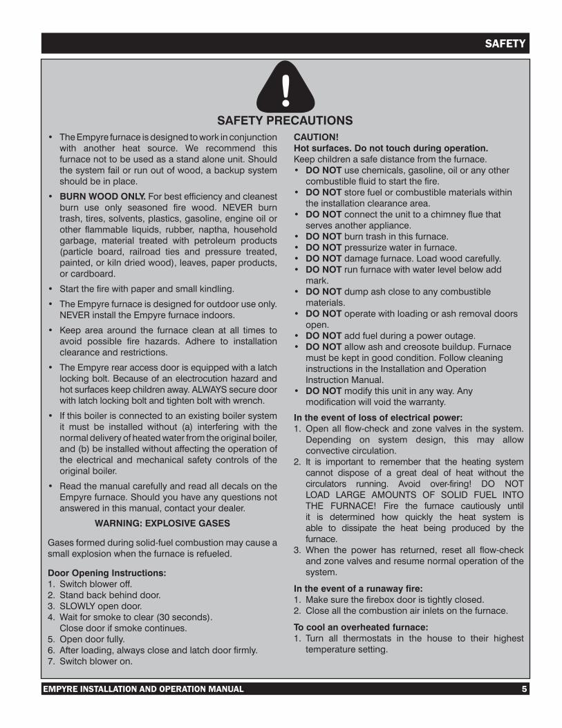
WARNING: EXPLOSIVE GASES
Gasesformedduringsolid-fuelcombustionmaycauseasmallexplosionwhenthefurnaceisrefueled.
Door Opening Instructions:1. Switchbloweroff.2. Standbackbehinddoor.3. SLOWLYopendoor.4. Waitforsmoketoclear(30seconds). Closedoorifsmokecontinues.5. Opendoorfully.6. Afterloading,alwayscloseandlatchdoorfirmly.7. Switchbloweron.
CAUTION!Hot surfaces. Do not touch during operation.Keepchildrenasafedistancefromthefurnace.• DO NOTusechemicals,gasoline,oiloranyothercombustiblefluidtostartthefire.
• DO NOTstorefuelorcombustiblematerialswithintheinstallationclearancearea.
• DO NOTconnecttheunittoachimneyfluethatservesanotherappliance.
• DO NOTburntrashinthisfurnace.• DO NOTpressurizewaterinfurnace.• DO NOTdamagefurnace.Loadwoodcarefully.• DO NOTrunfurnacewithwaterlevelbelowaddmark.
• DO NOTdumpashclosetoanycombustiblematerials.
• DO NOToperatewithloadingorashremovaldoorsopen.
• DO NOTaddfuelduringapoweroutage.• DO NOTallowashandcreosotebuildup.Furnacemustbekeptingoodcondition.FollowcleaninginstructionsintheInstallationandOperationInstructionManual.
• DO NOTmodifythisunitinanyway.Anymodificationwillvoidthewarranty.
In the event of loss of electrical power:1. Openall flow-checkandzonevalves in thesystem.Depending on system design, this may allowconvectivecirculation.
2. It is important to remember that the heating systemcannot dispose of a great deal of heat without thecirculators running. Avoid over-firing! DO NOTLOAD LARGE AMOUNTS OF SOLID FUEL INTOTHE FURNACE! Fire the furnace cautiously untilit is determined how quickly the heat system isable to dissipate the heat being produced by thefurnace.
3. When the power has returned, reset all flow-checkandzonevalvesandresumenormaloperationofthesystem.
In the event of a runaway fire:1. Makesurethefireboxdooristightlyclosed.2. Closeallthecombustionairinletsonthefurnace.
To cool an overheated furnace: 1. Turn all thermostats in the house to their highesttemperaturesetting.
SAFETY PRECAUTIONS
6 EMPYRE INSTALLATION AND OPERATION MANUAL
SAFETY
Canadian CSA RequirementsInstallation of the Empyre as an add-on unit in the Canadian provinces and territories must comply with the requirements of CAN/CSA-B365, and changes to the installation must comply with the following CSA requirements:
CSAB139–foroilfired
CSA C22.1 – for electric
CAN/CGA-B149.1orCAN/CGA-B149.2–forgasfired
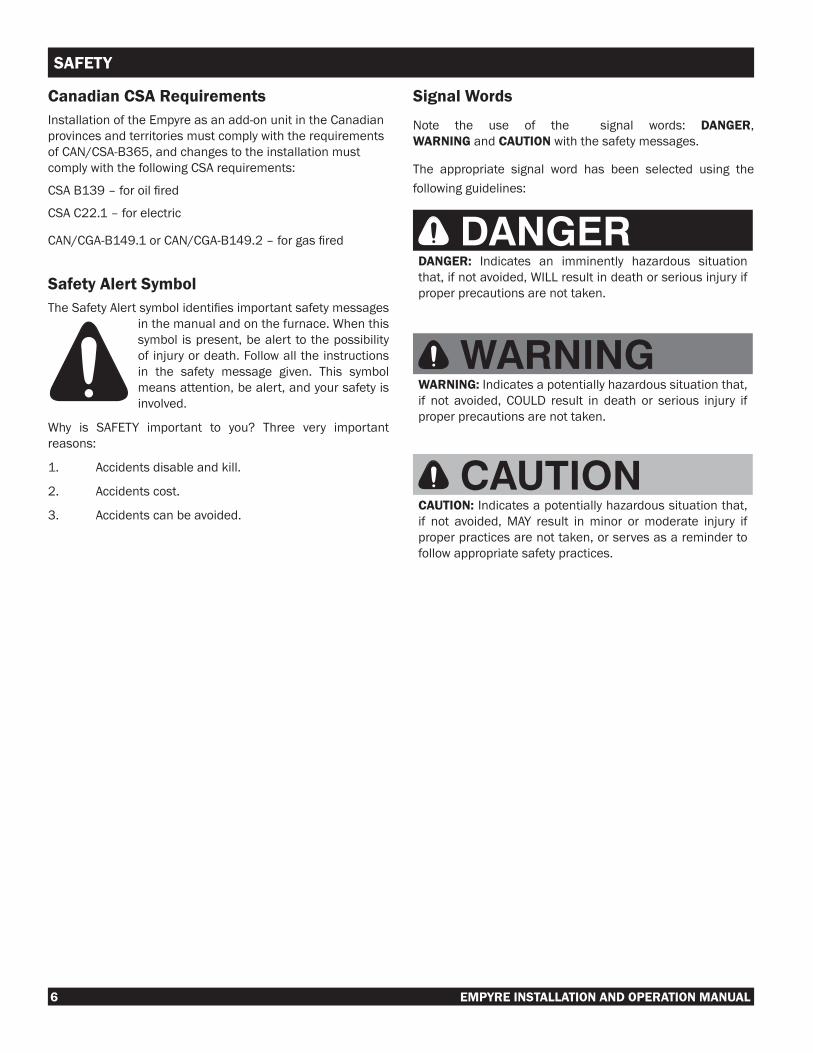
Safety Alert SymbolTheSafetyAlertsymbolidentifiesimportantsafetymessages
in the manual and on the furnace. When this symbol is present, be alert to the possibility of injury or death. Follow all the instructions in the safety message given. This symbol means attention, be alert, and your safety is involved.
Why is SAFETY important to you? Three very important reasons:
1. Accidents disable and kill.
2. Accidents cost.
3. Accidents can be avoided.
Signal Words
Note the use of the signal words: DANGER, WARNING and CAUTION with the safety messages.
The appropriate signal word has been selected using the following guidelines:
DANGERDANGER: Indicates an imminently hazardous situation that, if not avoided, WILL result in death or serious injury if proper precautions are not taken.
WARNINGWARNING: Indicates a potentially hazardous situation that, if not avoided, COULD result in death or serious injury if proper precautions are not taken.
CAUTIONCAUTION: Indicates a potentially hazardous situation that, if not avoided, MAY result in minor or moderate injury if proper practices are not taken, or serves as a reminder to follow appropriate safety practices.

EMPYRE INSTALLATION AND OPERATION MANUAL 7
SAFETY
Safety Decals
Please read and follow directions to ensure safe practices when using the Empyre furnace.
1) DANGER/WARNING/CAUTION - Located on left hand side of damper.2) FURNACE SERIAL DECAL - Located on left hand side of furnace.3) MAX. WOOD FILL TO TOP OF DOOR. - Located on top left hand corner of front door.4) THIS LID IS HEAVY. USE BOTH HANDS. - Located on back chimney cover.5) NOTE! MINIMUM 5 FT. OF INSULATED CHIMNEY IS REQUIRED FOR PROPER DRAFT. CLEAN CHIMNEY OUTLET REGULARLY.
COVER CHIMNEY WHEN FURNACE IS NOT IN USE. - Located left of the chimney cover.6) WIRING DIAGRAM - Located on rear access cover.7) ELECTRICAL - Located on the right front corner.8) SPECIFICATIONS - Located on the front left corner.
Note!
818645R00
• Minimum5ft.(1.52m)ofinsulatedchimneyisrequiredforproperdraft.
• Cleanchimneyoutletregularly.• Coverchimneywhenfurnaceisnotinuse.
RefertoBestBurnPracticesinOperator'sManual.
WARNING!
818649R00
THIS LID IS HEAVY.USE BOTH HANDS.
MAX. WOOD FILL TO TOP OF DOOR
818643R00
EMPYREOutdoor Wood Fired Hydronic Heater / Fournaise hydronique au bois extérieure
Electrical ratings: volts 120, 1 phase, 60HZ, 15 amps max.For outdoor use only.Boiler Fuel - Burn wood only.Shaker Grate Fuel - Coal or WoodUse only Flue Pipe that is approved by manufacturer.Base - Noncombustible, concrete preferred.Outdoor Wood Fired Hydronic Heater must be kept in good condition, clean chimney and firebox at end of season. Store wood and all combustible materi-als outside the installation clearances. Installation clearances: 60” (152 cm) above/ 48” (122 cm) front/ 6” (15 cm) from sides/ 18” (46 cm) from Flue pipe.Keep doors closed tightly.Do not pressurize. Risk of fire or explosion.Do not connect this unit to a chimney flue serving another appliance.Load fuel carefully to prevent damage to boiler.Do not burn garbage, gasoline, naphta or engine oil.Do not use chemicals or fluids to start fire.Never run boiler with water level below add mark.Do not leave door open, or dump ash tray close to any combustible materials, may lead to runaway fire.Refer to owner’s manual for complete instructions.
Manufactured by Pro-Fab Industries Inc.Arborg, Manitoba
MADE IN USA
Caractéristiques électriques: 120 volts, courant momphasé, 60HZ, max. de 15 ampères.Pour usage extérieur seulement.Combustible – Brûler seulement que du bois.Combustible agitateur – Charbon ou boisN’utiliser qu’un conduit de fumée approuvé par le fabricant.Base - Utiliser des matériaux incombustibles, de préférence du béton.Les appareils de chauffage au bois doivent être maintenus en bon état. Nettoyer le cheminée et la chambre de combustion à la fin de chaque saison. Entreposer le bois et toutes les matières combustibles suffisamment loin de l’appareil. Dégagement minimum: 152 cm (60 po) du plafond, 122 cm (18 po) à l’avant, 15 cm (6po) sur les côtes et 46 cm (18 po) du conduit de fumée.Garder les portes fermées hermétiquement.Faites l'aucun pressurisent. Risque de feu ou d’explosion.Ne pas raccorder l’unité à une cheminée desservant un autre appareil.Charger soigneusement l’appareil afin de prévenir les dommages.Ne pas brûler de déchets, de lessence, du napthe ou de l’huile à moteur.Ne pas utiliser de produits chimiques, solides ou liquides, pour allumer le feu.Ne pas faire fonctionner la fournaise avec le niveau d’eau sous l’indicateur de demande de rajout d’eau.Toujours fermer la porte de l’appareil et ne jamais vider un cendrier près de matières combustibles. Un incendie peut se déclarer très facilement.Consulter le manuel du propriétaire pour obtenir des instructions complètes.
Fabriqué par Pro-Fab Industries Inc.Arborg, Manitoba
FABRIQUÉ AU USA
818642R00
W/N 20740
CERTIFIED HEATING APPLIANCE □ EMPYRE 250 □ EMPYRE 450 APPAREIL DE CHAUFFAGE CSA STANDARD B366-1-M91 NORME B366-1-M91 DE LA CSA UL STANDARD 391, UL 762, UL 2523 SERIAL NO./N° DE SÉRIE ________________________ NORME 391, 762, 2523 DE ULCCERTIFIED AS AN ADD-ON MODEL 07/12 CERTIFIÉE COMME MODÈLE COMPLÉMENTAIRE, 07/12
1.
3.
2.
5.
4.
COZEBURNOutdoor Wood Fired Hydronic Heater / Fournaise hydronique au bois extérieure
CERTIFIED HEATING APPLIANCE MODEL NO./CERTIFIÉN DE MODÈLE_______________ APPAREIL DE CHAUFFAGE
CSA STANDARD B366-1-M91 SERIAL NO./N° DE SÉRIE________________________ NORME B366-1-M91 DE LA CSA
UL STANDARD 391, UL 762, UL 2523
NORME 391, 762, 2523 DE ULC
CERTIFIED AS AN ADD-ON MODEL 07/12
CERTIFIÉE COMME MODÈLE COMPLÉMENTAIRE, 07/12
Electrical ratings: volts 120, 1 phase, 60HZ, 15 amps max.For outdoor use only.Boiler Fuel - Burn wood only.Shaker Grate Fuel - Coal or WoodUse only Flue Pipe that is approved by manufacturer.Base - Noncombustible, concrete preferred.Outdoor Wood Fired Hydronic Heater must be kept in good condition, clean
chimney and firebox at end of season. Store wood and all combustible materi-
als outside the installation clearances. Installation clearances: 60” (152 cm)
above/ 48” (122 cm) front/ 6” (15 cm) from sides/ 18” (46 cm) from Flue pipe.Keep doors closed tightly.Do not pressurize. Risk of fire or explosion.Do not connect this unit to a chimney flue serving another appliance.Load fuel carefully to prevent damage to boiler.Do not burn garbage, gasoline, naphta or engine oil.Do not use chemicals or fluids to start fire.Never run boiler with water level below add mark.Do not leave door open, or dump ash tray close to any combustible materials,
may lead to runaway fire.Refer to owner’s manual for complete instructions.
Manufactured by Pro-Fab Industries Inc.MADE IN USA
Caractéristiques électriques: 120 volts, courant momphasé, 60HZ, max. de 15 ampères.Pour usage extérieur seulement.Combustible – Brûler seulement que du bois.Combustible agitateur – Charbon ou boisN’utiliser qu’un conduit de fumée approuvé par le fabricant.Base - Utiliser des matériaux incombustibles, de préférence du béton.Les appareils de chauffage au bois doivent être maintenus en bon état.
Nettoyer le cheminée et la chambre de combustion à la fin de chaque saison.
Entreposer le bois et toutes les matières combustibles suffisamment loin de
l’appareil. Dégagement minimum: 152 cm (60 po) du plafond, 122 cm (18 po)
à l’avant, 15 cm (6po) sur les côtes et 46 cm (18 po) du conduit de fumée.Garder les portes fermées hermétiquement.Faites l'aucun pressurisent. Risque de feu ou d’explosion.Ne pas raccorder l’unité à une cheminée desservant un autre appareil.Charger soigneusement l’appareil afin de prévenir les dommages.Ne pas brûler de déchets, de lessence, du napthe ou de l’huile à moteur.Ne pas utiliser de produits chimiques, solides ou liquides, pour allumer le feu.Ne pas faire fonctionner la fournaise avec le niveau d’eau sous l’indicateur de
demande de rajout d’eau.Toujours fermer la porte de l’appareil et ne jamais vider un cendrier près de
matières combustibles. Un incendie peut se déclarer très facilement.Consulter le manuel du propriétaire pour obtenir des instructions complètes.
Fabriqué par Pro-Fab Industries Inc.FABRIQUÉ AU USA
818640R00
W/N 20740
1
3
2
45
7 8.
7
6.
8
6

8 EMPYRE INSTALLATION AND OPERATION MANUAL
FEATURES
8
7
12
10
6
2
1
9
11
5
13
16
17
2019
18
1514
11
4
3
Indentifying Main ComponentsNo. Description No. Description
1 Insulated Chimney 11 Forklift Lifting Guides2 Light 12 Legs3 Light & Power Switch,
Manual Reset Breaker13 Rear Access Cover
4 Aquastat and Thermostat
14 Drain
5 Control Panel Cover 15 Junction Box6 Loading Door 16 Supply/Return Hookups7 Solenoid & Blower
(behind cover)17 Chimney Clean Out Cover
8 Damper (behind cover) 18 Roof9 Pressure Touch Door
Handler19 Top Lifting Hook
10 Removable Ash Tray 20 Vent & Water Level Indica-tor

EMPYRE INSTALLATION AND OPERATION MANUAL 9
INSTALLATION
Suggested Material Required to Complete an Installation
For the installation of a single family residential hookup with the furnace approximately 50 feet (15.24 m) from the building to be heated, the following will be required:
a. Empyre Outdoor Wood Stove (furnace)
b. Concrete pad for furnace base
c. 150 feet (45.72 m) of supply and return line
d. 50 feet (15.24 m) of underground line insulation
e. Forced air furnace heat exchanger (radiator or coil)
f. Domestic hot water tank heat exchanger (optional)
g. Circulating pump
h. Pipefittings
i. Two ball valves
j. Approved rust inhibitor
k. Thermostat
l. Installation and Operation Instruction Manual
Site Requirements
1. The Empyre furnace must be installed on a noncombustible floorpad,suchasconcreteorpatioblocks.
2. There must be a minimum clearance between the furnace and any combustible material as follows:
From top of furnace 60 inches (152 cm)
From front of furnace 48 inches (122 cm)
From side of furnace 6 inches (15 cm)
From rear of furnace 48 inches (122 cm)
Fromfluepipes18inches(46cm)
3. Install the furnace in a location that best suits wind direction for your home and building(s) and neighbouring residents.
Consultwithaninsuranceprovidertoconfirmacceptablefurnace installation distance from all buildings.
4. The Canadian Standards Association requires a minimum 5 feet (1.52 m) of insulated chimney in order to obtain the best draft in the furnace.
5. Installation of the Empyre furnace must be completed in accordance with local, state, provincial or federal building andfirecodeswhichmaydifferfromthismanual.
IMPORTANT: Contact an insurance provider prior to installation to ensure that installation is in compliance with local insurance requirements and all terms have been met.

10 EMPYRE INSTALLATION AND OPERATION MANUAL
INSTALLATION
Trench for Underground Pipes
1. The water lines must be properly insulated to minimize heat loss. Ask your dealer for the right underground water line insulation.
2. Dig a trench, ideally 24” (61 cm) deep* and 12” (31 cm) wide, and make as level as possible to avoid damage to the tubing.
*Trench should be at least 36” (92 cm) deep under driveways.
3. The water lines should be a minimum of 3/4” (2 cm) inside dimensions*, rated and approved for use with high temperature water and antifreeze.
*Size of water lines depends on distance; check with a qualified heating professional to determine the linesize necessary to meet the demands of your specificapplication.
Note: Size of piping must be such that excessive pressure will not be developed in any portion of the boiler system.
4. Identify each water line clearly in order to correctly locate the hot and return lines.
5. Lay down 14-2 underground wire approved for underground installation. Obtain the required electrical permit and confirm local electrical code requirementsprior to installation.
House
Shop
InsulatedLines
Typical Installation
WaterLines
Foundation Dimensions
1. The furnace should be installed on a concrete pad.* Slope the pad 1/2” (1.27 cm) towards the front of the furnace in order to drain off any condensation that may accumulate in the ash tray. *For furnaces without legs an option is to heighten the pad for easier loading and ash tray removal.
2. If the soil is somewhat unstable, a good bed of crushed rock or a grade beam will help prevent the furnace from shifting.
CPW250 CPW450in cm in cm
A 4 10 5 13B 49 124 55 140C 64 163 82 208D 6 15 6 15E 10 25 10 25F 31 79 37 94

EMPYRE INSTALLATION AND OPERATION MANUAL 11
INSTALLATION
Chimney Installation Install a 1 inch (2.54 cm) wall thickness insulated chimney that is listed to ULC-S610 and ULC-S604 standards. Apply a bead of high temperature silicone on the outside of the chimney. For tall chimneys, chimney braces are recommended. Pro-Fab Industries recommends a minimum chimney length of 5 feet (1.52 m).
Not less than 2 ft (.61 m)
When water is to be pumped uphill, pump must be located in the hot water supply line at the furnace.
Furnace Flue DiameterEmpyre 250 6” (15 cm)Empyre 450 8” (20 cm)
Installing the FurnaceWe recommend that the furnace be installed by a qualified installer.Position furnace on pad. Note: Lift only by top lifting hook or bottom forklift guides. Use caution! Furnace is heavy.Once the unit has been placed into position, remove the back cover and the light globe from the firebox andinstall.Type “A” furnace requires a tight silicone seal around the base to keep out rodents, etc. The furnace is now ready to hookup the heater to the underground water lines.1. Install shut off valves on all lines
attached to the furnace to prevent loss of water during maintenance and repairs. Fittings and valves to be attached to the furnace should either be stainless steel or brass.
2. IMPORTANT: A spark arrester must be installed if the Empyre Outdoor Wood Burning Furnace is used in a high fire riskarea.
3. The water circulating pump must be mounted in the hot supply line several feet below the top of the furnace water level to minimize air lock problems, see Figure 1, 2, or 3.
IMPORTANT: Pump must always be in lowest part of the line system and horizontal with the ground, see Figure 4.
12 EMPYRE INSTALLATION AND OPERATION MANUAL
INSTALLATION
IMPORTANT:
The installation drawings in this manual are typical layouts shown as examples of types of layout only. We recommend that you engage a professional plumbing and heating company to ensure that your installation is suitable for your application, will serve your needs and conform to all local codes.
The Pro-Fab Industries warranty covers the Empyre furnace only and does not include anything outside of the Empyre furnace. Pro-Fab Industries takes NO responsibility for faulty installations, etc. DO NOT modify this unit in any way. Any modification will void the warranty.
These drawings should help in establishing a list of material required for a typical installation. All parts should be available from your Empyre provider. Ask your dealer for a parts list.
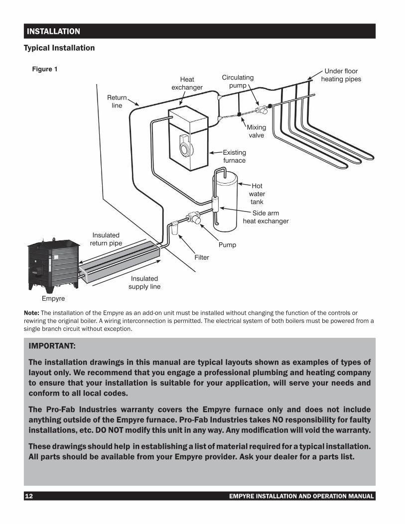
Empyre
Insulatedsupplyline
Insulatedreturnpipe
Filter
Pump
Sidearmheatexchanger
Hotwatertank
Existingfurnace
Circulatingpump
Mixingvalve
Heatexchanger
Returnline
Underfloorheatingpipes
Figure 1
Typical Installation
Note: The installation of the Empyre as an add-on unit must be installed without changing the function of the controls or rewiring the original boiler. A wiring interconnection is permitted. The electrical system of both boilers must be powered from a single branch circuit without exception.

EMPYRE INSTALLATION AND OPERATION MANUAL 13
INSTALLATION
Hookup to Existing Heat System (Water to Air)
1. Install the circulating pump on the supply line and ensure that the pump’s motor is in a horizontal position.
2. Install the heat exchange radiator in the hot air plenum of the forced air furnace, Figure 2, according to the manufacturer’s instructions, taking care to seal all joints and holes.
3. After installing the heat exchanger to the forced air furnacesystem,checktoensurethattheairflowisthesameasspecifiedbythemanufacturerof theexistingheating system. The furnace fan should not generally need to be changed in order to accommodate the addition of the heat exchanger.
Belt Driven Hot Air Fan
4. Pulleys on motor and blower may have to be adjusted to get theproperrateofairflow.
Direct Drive Fan
5. Adjust the motor speed to obtainthecorrectairflow.
Thermostat
6. Install a second thermostat to allow the blower to cut in separately from the furnace.
7. The existing thermostat should be set several degrees lower than the new thermostat. This will allow the regular system to cut in, should the Empyre run out of wood and the temperature drop below the second setting.
IMPORTANT: Have a qualified electrician check to ensurethat these changes do not cause the electrical motor to be overloaded. Any modification to the EXISTING forced air heating system must be made in accordance with the manufacturer’s specifications and performed by qualified, licensed personnel in accordance with local building codes.
Under Floor Heat
1. A 24 V thermostat with relay should be used in a house. For garage or shop, wire pump through an in-line thermostat.
2. Each zone can be manually adjusted with the ball valves on the supply header.
3. Adjust mixing valve to run supply water temperature between110˚F-120˚F(43˚C-49˚C)inconcretefloorinstallation.
Figure 2
Figure 3
Returnheader

14 EMPYRE INSTALLATION AND OPERATION MANUAL
INSTALLATION
Optional Heat ExchangerStainless Steel Water to Water Heat Exchanger, Figure 2, can be used in place of a side arm.
COLDWATER
MIXEDWATER
TEMPERINGVALVE
Hotwater Usedforbleedingair
WATERHEATER
Useforfillingsystem
Supplyfromfurnace
Toheatingsystem
Waterheaterdrain
CAUTIONDonoteliminatetheexistingtemperaturereliefvalve.
SIDEARMHEATEXCHANGER
NOTE:Keepbottomloop(andsidearm)aslowaspossible.
PUMP
BALLVALVE
THERMOMETER
BOILERDRAIN
TEMPERINGORMIXINGVALVE
SYMBOL INDEX
Have a qualified electricianand plumber check to ensureall connections to the furnaceare in accordance with themanufacturer’s specifications andperformed by qualified, licensedpersonnel in accordance withlocalbuildingcodes.
Side Arm Installation
Toheatingsystem
Hotwaterinfromfurnace
Totopofhotwatertank
Frombottomofhotwatertank
Figure 1
Figure 2
IMPORTANT
When hooking up the Empyre to a
domestic hot water heater, a tempering valve must be installed, to prevent scalding hot water from reaching the hot water outlets.
Valve
EMPYRE INSTALLATION AND OPERATION MANUAL 15
INSTALLATION
Plateheatexchanger
CirculatingPump
Existingwater/airheatingcoilReturn
Supply
ExistingFurnaceorBoiler
Expansiontankwithfill/drainvalvesandbackflowpreventionvalve
CirculatingPump
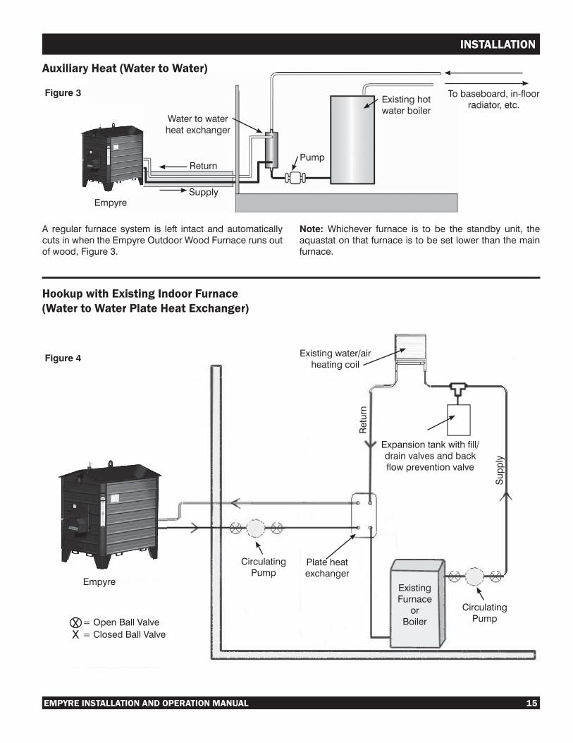
A regular furnacesystem is left intact andautomaticallycutsinwhentheEmpyreOutdoorWoodFurnacerunsoutofwood,Figure3.
Note: Whichever furnace is to be the standby unit, theaquastatonthatfurnaceistobesetlowerthanthemainfurnace.
Auxiliary Heat (Water to Water)
Empyre
Figure 3
Hookup with Existing Indoor Furnace (Water to Water Plate Heat Exchanger)
Empyre
Figure 4
Watertowaterheatexchanger
Return
Supply
Existinghotwaterboiler
Tobaseboard,in-floorradiator,etc.
Pump
=OpenBallValve=ClosedBallValveX
X
16 EMPYRE INSTALLATION AND OPERATION MANUAL
INSTALLATION
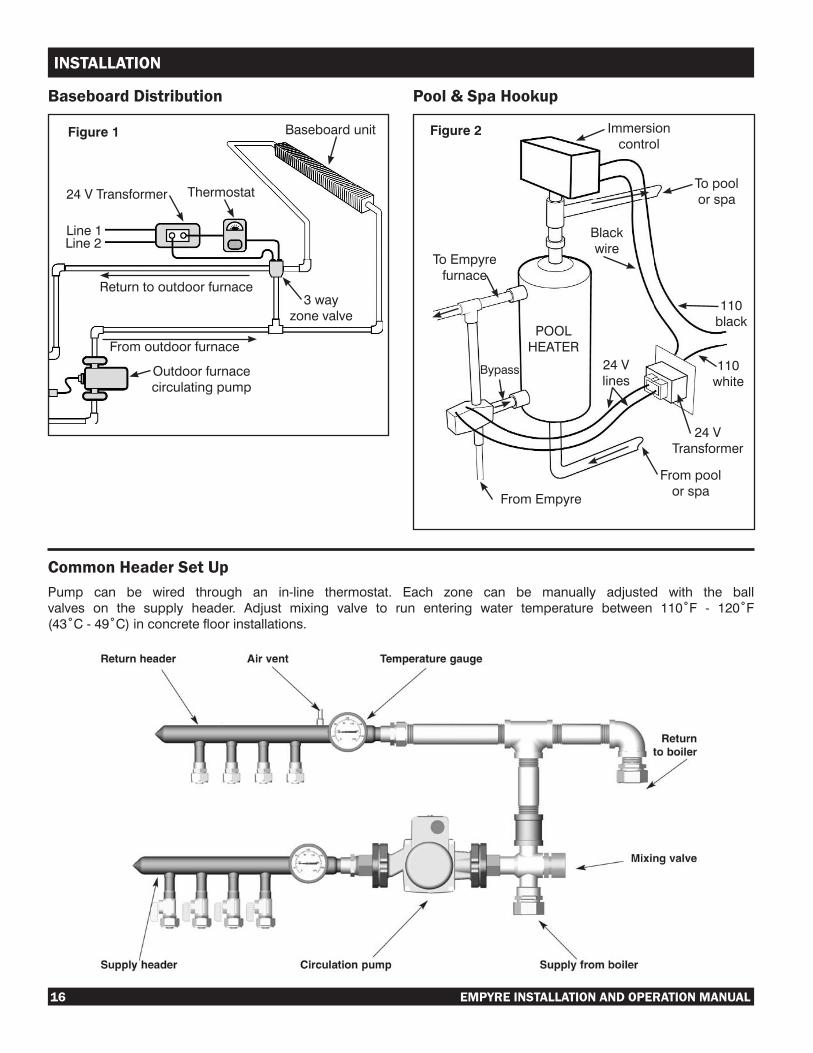
Baseboard Distribution Pool & Spa Hookup
24VTransformer Thermostat
Line1Line2
Outdoorfurnacecirculatingpump
Returntooutdoorfurnace3way
zonevalve
Baseboardunit
Fromoutdoorfurnace
Figure 1 Figure 2
ToEmpyrefurnace
FromEmpyre
Frompoolorspa
110white
110black
Immersioncontrol
Blackwire
24Vlines
POOLHEATER
Bypass
24VTransformer
Topoolorspa
Common Header Set UpPump can be wired through an in-line thermostat. Each zone can be manually adjusted with the ballvalves on the supply header. Adjust mixing valve to run entering water temperature between 110˚F - 120˚F(43˚C-49˚C)inconcretefloorinstallations.

EMPYRE INSTALLATION AND OPERATION MANUAL 17
OPERATION
VentopeningFigure 3
KEEP THE VENT OPENING ON TOP OF THE FURNACE CLEAR OF ANY OBSTRUCTIONS.
IMPORTANT:1. Useonlysoft,clean,filteredwaterintheEmpyre.
Add Pro-Fab approved water treatment to thewater to prevent corrosion (available from yourEmpyredealer).
2. Addapprovedantifreezetothewaterchambertopreventfreezingshouldthefurnaceandthepumpshutdownduetoapowerfailureorothercause.Foramountofantifreezetoaddfollowinstructionsonthecontainer.
Use only environmentally friendly, propylene glycol based, low toxicity, non-petroleum based antifreeze designed for use in hot water furnace systems.
AvailablefromyourEmpyredealer.
First Fill
1. To fill the furnace with water from the inside of thebuilding being heated, install a plumbing “T” in the return or supply line complete with a check valve and boiler drain, see Figure 4.
2. Attach a garden hose, with two female ends, from the watersupplytothefillervalve.
3. Isolate the furnace by closing off supply and return valves securely at the back of the furnace.
IMPORTANT: The Empyre may need to be drained of its contents at some time in the future. Be sure to place the line fill/drainassembly ina locationwherewater caneasilybedrained and will not cause damage to the surrounding area.
Figure 4
4. Turn on the water to pressurize the line system and check for leaks in the system.
DO NOT PRESSURIZE THE FURNACE.
5. CHECK ALL LINES AND CONNECTORS FOR LEAKS.
6. After checking for leaks in system, open the SUPPLY valve at the furnace and let water run for 2 minutes and then close it.
7. Now open the RETURN valve at the furnace and let water run for 2 minutes and then close it.
8. Repeataboveprocedure3to4timesduringfillingofthefurnace. Alternating between lines will ensure that most of the air is bled from the system.
9. When the Empyre is full, shut off water and close the in-linefillervalveanddisconnectthegardenhose.
10. Mix Pro-Fab approved water treatment, with one to two gallons of warm water and pour through vent opening, Figure 3.
Maintaining Proper Water Level
Whenwaterlevelislow,theEmpyremaybefilledortoppedupthrough the vent opening, Figure 3.

18 EMPYRE INSTALLATION AND OPERATION MANUAL
OPERATION
Starting the Fire in the Outdoor Hot Water Wood Furnace Once the Empyre has been properly installed, all connections checked thoroughly and the water system is filled to theproperlevel,theunitisreadyforstartingafire.1. Placesomedrysplitkindlingatthebackofthefirebox,
on top of some paper, and ignite.2. Once the kindling begins to burn, add large pieces of
wooduntilthefireburnsbriskly.Donotfillthefireboxofthe furnace to capacity until the water in the furnace is hot.
3. Only put enough wood into the furnace as may be burned duringatwelvehourperiod.Donotfillthefireboxabovethe top of the loading door.
A small intense fire burns cleaner and is preferableto long smoldering fires which may create excessivecreosote deposits in the chimney.
DO NOT OPERATE WITH LOADING OR ASH REMOVAL DOORS OPEN.DO NOT USE THE DOOR AS A LEVER TO FORCE WOOD INTO THE FIREBOX!Note: The Empyre has been pressure tested at the factory for water leaks. Some condensation may be observed in the fireboxwhile the furnace is heating up after thewater hasbecome completely cold.
INCORRECTTightlypackedwoodwillreduceairflowforpropercombustion.
CORRECTWood will burncleanerandbetterifexhaust passage iskeptopen.

EMPYRE INSTALLATION AND OPERATION MANUAL 19
OPERATION
OUTDOOR BEST BURN PRACTICES
1. Read and follow all operating instructions supplied by the manufacturer.
2. FUEL: Use only those fuels recommended by the manufacturer of the unit. Never use the following: trash, plastics, gasoline, rubber, naphtha, household garbage, material treated with petroleum products (particle board, railroad ties and pressure treated wood), leaves, paper products, and cardboard.
3. LOADINGFUEL:Foramoreefficientburn,paycarefulattentiontoloadingtimesandamounts.Followthemanufacturerswritten instructions for recommended loading times and amounts.
4. STARTERS:Donotuselighterfluids,gasoline,orchemicals.
5. LOCATION: It is recommended that the unit be located with consideration to prevailing wind direction.
▪Furnaceshouldbelocatednolessthan100feetfromanyresidencenotservedbythefurnace.
▪Iflocatedwithin100feetto300feetofanyresidencenotservedbythefurnace,itisrecommendedthatthestackbeatleast two feet higher than the peak of that residence.
6. Always remember to comply with all applicable state/provincial and local codes.
OUTDOORFURNACEMANUFACTURER’SCAUCUS
20 EMPYRE INSTALLATION AND OPERATION MANUAL
MAINTENANCE
During Heating Season1. Inspect the vent periodically for any blockages. Always
ensurethattheventcapfitslooselyinordertopreventthe unit from becoming pressurized.
The Empyre is designed as an “Open to Atmosphere” system and should never be under pressure!
2. The ash tray must be checked weekly and emptied as necessary. Ensure that the ash tray is securely closed after each cleaning. Adjust the latch if necessary.
Ashes should be placed in a metal container with a tight fitting lid. The closed container of ashes shouldbeplacedonanoncombustiblefloororontheground,wellaway fromall combustiblematerial,pendingfinaldisposal. Other waste should not be placed in the container with the ashes.
3. Check the water level at least once a week to ensure the level is well above the “ADD” mark.
Oxygen buildup causes corrosion inside the water system. Keeping the water reservoir completely full avoids oxygen buildup, especially during the summer months when the furnace is not in use.
4. Check the door gasket to ensure an air tight fit andmaintain in good condition. Replace if necessary.
5. Turn off power.6. Check and clean the damper cover to prevent creosote
buildup. Do this weekly until experience shows how often cleaning is necessary.
A creosote buildup could cause the damper to seize, causing the circuit breaker to disengage.
7. Inspect the chimney and chimney connector monthly during the heating season to determine if a creosote buildup has occurred. Maintain and clean if there is a buildup of creosote. When wood is burned slowly, it produces tar and other organic vapors, which combine with expelled moisture to form creosote. The creosote vapors condense in the relatively cool chimney flueof a slow burning fire. As a result, creosote residueaccumulates on the flue lining. When ignited, thiscreosotemakes an extremely hot fire. Whenburningwood, the chimney connector and chimney should be inspected monthly during the heating season, and if creosote has accumulated, it must be removed to reducetheriskofachimneyfire.
A buildup of creosote will also cause a poor draft.8. Cover plates and guards must be in place at all times,
except during maintenance and servicing.
9. Canadian requirements for supplementary (add-on) boilers:
- operate the original gas, oil or electric boiler periodically to ensure that it will operate satisfactorily when needed;
- do not relocate or bypass any of the safety controls in the original gas, oil or electric boiler installation;
-the operation of a gas boiler must be verified foracceptable operation, before and after installation of theadd-onappliance,byagasfitterwhoisrecognizedby the local and national regulatory authority;
- do not connect to any chimney or vent serving a gas appliance.
End of Heating SeasonCleaningoftheheatexchanger,fluepipe,chimneyanddraftinducer if used, is especially important at the end of the heating season to minimize corrosion during the summer months caused by accumulated ash.1. Thoroughly clean the furnace of any creosote or ash
buildup. Hardened creosote or ashes are easier to be removed
when furnace is still warm.2. Check to ensure there is no moisture in any part of the
insideofthefirebox,orintheashtray. Failing to properly clean the furnace and protect it
from moisture during the off-season will void the warranty.
3. Cover and seal the chimney to prevent any rain or moisturefromenteringthefireboxchamberwhilenotinuse.
4. Ensure the water reservoir is full during the non-heating season to prevent corrosion inside the water jacket.
5. Add a sufficient amount of Pro-Fab approved watertreatment to the water system each year after the heating season. Operate the water circulating pump for 24 hours after adding water treatment to ensure proper mixing of the water treatment with the water.
6. A water sample must be drawn 30 days after purchase of the unit and forwarded to your dealer for testing. Maintain the results of this test on file. Thereafter, draw awatersample once a year and forward to your dealer for testing.
Water properly treated with Pro-Fab approved water treatment should be between 8.8 and 11.0, a nitrate level between 730 and 1460 ppms as NaNO2, and a conductivity must be less than or equal to 4000 mmhos.
If the pH or nitrite level is low, more Pro-Fab approved water treatment should be added. If the level of conductivity is too high, 1/2 the water in the unit should be drained and replaced with fresh water.
Failing to use Pro-Fab approved water treatment in accordance with the Installation and Operation Instructions will void the warranty. See your dealer for authorized supplies. It is the responsibility of the owner to maintain yearly water sample results on file.

EMPYRE INSTALLATION AND OPERATION MANUAL 21
MAINTENANCE
Cleaning the Ash Tray
1. The ash tray must be checked weekly and emptied as necessary. Ensure that the ash tray is securely closed after each cleaning.
2. Toavoidabuildupofashesinthefirebox,stirashesdaily to allow them to fall through to the ash tray. Keep ashes away from the air injection tubes.
Caution:Ashesshouldberemovedwhenfireisout,do not remove burning material or glowing embers.
3. Ashes should be placed in a metal container with a tightfittinglid.Theclosedcontainerofashesshouldbe placed on a noncombustible floor or on theground, well away from all combustible materials, pendingfinaldisposal.Iftheashesaredisposedofby burial in soil or otherwise locally dispersed, they should be retained in the closed container until all cinders have thoroughly cooled.
Power OutagesTheEmpyrefurnace,unlikeagasoroilfiredappliance,doesnot stop generating heat when the power is interrupted even thoughtheblowerautomaticallyshutsoffcausingthefiretodiedown.Asaresulttheheattransferfluidinthefurnacemayover heat and boil off through the vent. When power resumes besuretocheckthefluidlevel.

22 EMPYRE INSTALLATION AND OPERATION MANUAL
REFERENCE
Operating the Digital Temperature Switch (DTS)
DTS Description
The digital temperature switch is designed for many heating and cooling applications. The probe temperature (Figure 1) is displayed on the bright 3-digit, red light emitting diode (LED). The user is able to adjust the set point using the front keypad. The unit features a 16 amp, single pole, double throw (SPDT) relay with the temperature display in degrees Fahrenheit.
DTS Wiring Diagram
DTS Display Messages
In normal operation, the probe temperature will be shown on the display. In case of an alarm or error, the following messages will be shown:
Er = Memory error
-- = Short-circuit probe error
∞=Openprobeerror
DTS Physical Data
Accuracy: ±1°
Output: 16 Amp SPDT relay
Supply voltage: 110 V
Front panel protection: NEMA 4 (lp65)
Display: 3-digit, red. Digit height: 1/2” (1.27 cm)
DTS Programming
• PressSET.SPtextwillappearonthedisplay.
• PressSETagain.Therealvalueisshownonthedisplay.
• The value can be modified with the UP and DOWNarrows.
• PressSETtoenternewvalues.
• Press SET and DOWN at the same time to exitprogramming or wait one minute and the display will automatically exit the programming mode.
NOTE: Only the temperature setting is programmable. All other settings are locked.
DTS Maintenance/Repair
After final installation of the digital temperature switch,no routinemaintenance is required. Thisdevice isnot fieldrepairable and should be returned to the factory if recalibration or other service is required.
AnymodificationortamperingwiththefactorysettingsoftheDTS will void the furnace warranty.
Figure 1
EMPYRE INSTALLATION AND OPERATION MANUAL 23
REFERENCE
1
3 2
5
4
67
8
9
10
Red
Black Power LineWhite Natural Line
LineLine
Ground110 Volts AC
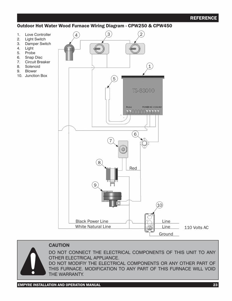
Outdoor Hot Water Wood Furnace Wiring Diagram - CPW250 & CPW450
1. LoveController2. LightSwitch3. DamperSwitch4. Light5. Probe6. SnapDisc7. CircuitBreaker8. Solenoid9. Blower10. JunctionBox
CAUTION
DONOTCONNECTTHEELECTRICALCOMPONENTSOFTHISUNIT TOANYOTHERELECTRICALAPPLIANCE.DONOTMODIFIYTHEELECTRICALCOMPONENTSORANYOTHERPARTOFTHISFURNACE.MODIFICATIONTOANYPARTOFTHISFURNACEWILLVOIDTHEWARRANTY.
24 EMPYRE INSTALLATION AND OPERATION MANUAL
REFERENCE
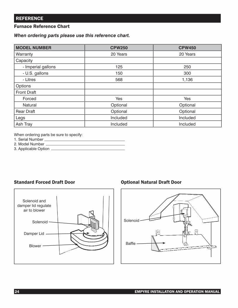
Standard Forced Draft Door
Solenoidanddamperlidregulateairtoblower
Solenoid
DamperLid
Blower
Solenoid
Baffle
Furnace Reference Chart
When ordering parts please use this reference chart.
MODEL NUMBER CPW250 CPW450Warranty 20Years 20YearsCapacity -Imperialgallons 125 250 -U.S.gallons 150 300 -Litres 568 1,136OptionsFrontDraft Forced Yes Yes Natural Optional OptionalRearDraft Optional OptionalLegs Included IncludedAshTray Included Included
Whenorderingpartsbesuretospecify:1.SerialNumber2.ModelNumber3.ApplicableOption
Optional Natural Draft Door
EMPYRE INSTALLATION AND OPERATION MANUAL 25
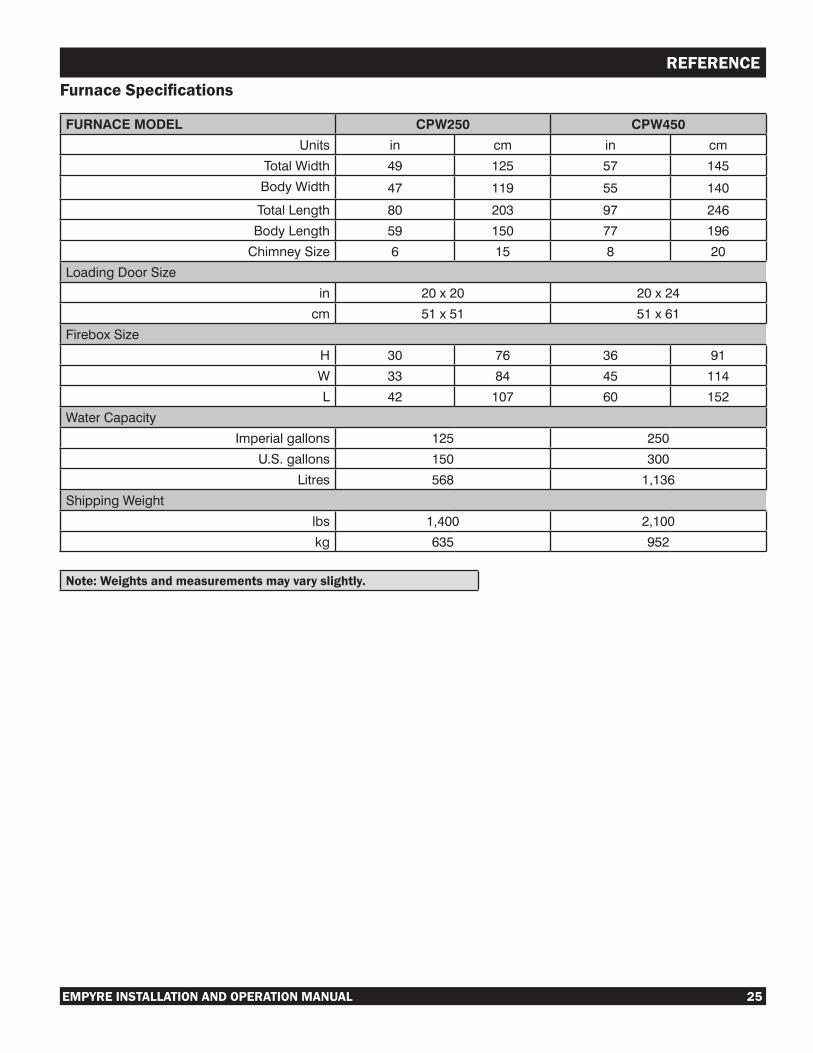
REFERENCEFurnace Specifications
FURNACE MODEL CPW250 CPW450
Units in cm in cm
TotalWidth 49 125 57 145
BodyWidth 47 119 55 140
TotalLength 80 203 97 246
BodyLength 59 150 77 196
ChimneySize 6 15 8 20
LoadingDoorSize
in 20x20 20x24
cm 51x51 51x61
FireboxSize
H 30 76 36 91
W 33 84 45 114
L 42 107 60 152
WaterCapacity
Imperialgallons 125 250
U.S.gallons 150 300
Litres 568 1,136
ShippingWeight
lbs 1,400 2,100
kg 635 952
Note: Weights and measurements may vary slightly.
26 EMPYRE INSTALLATION AND OPERATION MANUAL
TROUBLESHOOTING
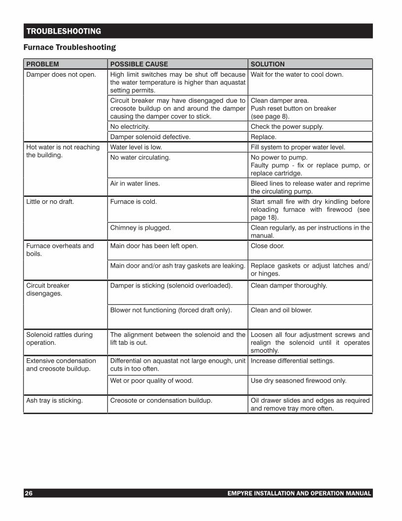
Furnace Troubleshooting
PROBLEM POSSIBLE CAUSE SOLUTION
Damperdoesnotopen. High limit switchesmaybe shut off becausethewatertemperatureishigherthanaquastatsettingpermits.
Waitforthewatertocooldown.
Circuitbreakermayhavedisengageddue tocreosotebuilduponandaround thedampercausingthedampercovertostick.
Cleandamperarea.Pushresetbuttononbreaker(seepage8).
Noelectricity. Checkthepowersupply.
Dampersolenoiddefective. Replace.
Hotwaterisnotreachingthebuilding.
Waterlevelislow. Fillsystemtoproperwaterlevel.
Nowatercirculating. Nopowertopump.Faulty pump - fix or replace pump, orreplacecartridge.
Airinwaterlines. Bleedlinestoreleasewaterandreprimethecirculatingpump.
Littleornodraft. Furnaceiscold. Start small fire with dry kindling beforereloading furnace with firewood (seepage18).
Chimneyisplugged. Cleanregularly,asperinstructionsinthemanual.
Furnaceoverheatsandboils.
Maindoorhasbeenleftopen. Closedoor.
Maindoorand/orashtraygasketsareleaking. Replace gaskets or adjust latches and/orhinges.
Circuitbreakerdisengages.
Damperissticking(solenoidoverloaded). Cleandamperthoroughly.
Blowernotfunctioning(forceddraftonly). Cleanandoilblower.
Solenoidrattlesduringoperation.
Thealignmentbetween thesolenoidand thelifttabisout.
Loosen all four adjustment screws andrealign the solenoid until it operatessmoothly.
Extensivecondensationandcreosotebuildup.
Differentialonaquastatnotlargeenough,unitcutsintoooften.
Increasedifferentialsettings.
Wetorpoorqualityofwood. Usedryseasonedfirewoodonly.
Ashtrayissticking. Creosoteorcondensationbuildup. Oildrawerslidesandedgesasrequiredandremovetraymoreoften.

EMPYRE INSTALLATION AND OPERATION MANUAL 27
TROUBLESHOOTING
Digital Controller Troubleshooting
PROBLEM POSSIBLE CAUSE SOLUTION
TheLOW(redlight)isonbutthewateriscompletelyfull.(Ifapplicable)
Thefrontrelayand/orthebottomlevelswitchisfaulty.
Unplugthethinredwirefromfrontrelaypole#3asshownonthewiringdiagram.Ifthepowertothedamper(andblower)is restored, replace the front relay. Ifneededreplacethebottomlevelswitch.
Thewateroverheatedandboiledoverandnowafterrefillingit,thewatertemperatureisbelowoperatingrangebutthereisnopowercomingthroughtothedamper(andblower).
TheHighLimitSwitch(snapdisc)hastrippedthecircuit.
Thishighlimitswitchisdesignedtoresetautomatically when the temperaturedrops down to approximately 130°F(54°C). When the snap disc function isdefaultedthepowershouldberestored.
Thedemandforheatisonwithsufficientwoodinthefireboxbutnopoweriscomingtothedamper(andblower).
The damper lid may be stuck causing theResetSwitchtopopout.
Loosenthedamperlidandpushinresetbutton.
Whilereloadingthefireboxthereseemstobeanexcessiveamountofsmokecomingoutofthedoor(morethanusual).
Thedraftisrestrictedduetocreosotebuildupinthechimneystack.
Clean the chimney stack,most builduptendstobeatthetopofthestack.
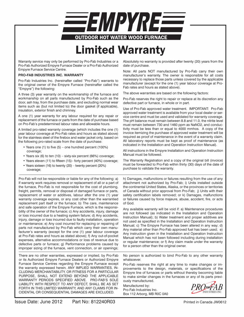
IssueDate:June2012 PartNo:812240R03 PrintedinCanadaJW0612
Limited WarrantyWarrantyservicemayonlybeperformedbyPro-FabIndustriesoraPro-FabAuthorizedEmpyreFurnaceDealeroraPro-FabAuthorizedEmpyreFurnaceServiceCentre.
PRO-FAB INDUSTRIES INC. WARRANTY
Pro-Fab Industries Inc. (hereinaftercalled “Pro-Fab”)warrants totheoriginalownerof theEmpyreFurnace (hereinaftercalled the“Empyre”)thefollowing:
Athree(3)yearwarrantyontheworkmanshipofthefurnaceandworkmanshiponallpartsmanufacturedbyPro-Fabsuchas thedoor,ashtray,fromthepurchasedate,andexcludingnormalwearitemssuchas(butnot limitedto)thedoorgasket(ifapplicable),insulation,exteriorfinishandchimney.
Aone (1) yearwarranty for any labour required for any repair orreplacementofthefurnaceorpartsfromthedateofpurchasebasedonPro-Fab’spredeterminedlabourratesandallowablehours.
Alimitedpro-ratedwarrantycoverage(whichincludestheone(1)yearlabourcoverageatPro-Fabratesandhoursasstatedabove)forthestainlesssteelofthefireboxandwaterjacketonly,basedonthefollowingpro-ratedscalefromthedateofpurchase:
•Yearsone(1)tofive(5)–onehundredpercent(100%)coverage;
•Yearssix(6)toten(10)–sixty-sixpercent(66%)coverage; •Yearseleven(11)tofifteen(15)–fortypercent(40%)coverage; •Yearssixteen(16)totwenty(20)–twentypercent(20%)
coverage;
Absolutelynowarrantyisprovidedaftertwenty(20)yearsfromthedateofpurchase.
Note: All parts NOT manufactured by Pro-Fab carry their ownmanufacturer’s warranty. The owner is responsible for all costsnecessarytoreplacethosepartsunlesscoveredbytheapplicablemanufacturer(exceptfortheone(1)yearlabourcoverageatPro-Fabratesandhoursasstatedabove).
Theabovewarrantiesarebasedonthefollowingfactors:
Pro-Fabreservestherighttorepairorreplaceatitsdiscretionanydefectivepartorfurnace,inwholeorinpart.
UseofPro-Fabapprovedwatertreatment.IMPORTANT:Pro-Fabapprovedwatertreatmentisavailablefromyourlocaldealerorser-vicecentreandmustbeusedandvalidatedforwarrantycoverage.ThepHbalancemustremainbetween8.8and11.0,thenitritelevelmustremainbetween730and1460ppmasNaNO2,andconduc-tivitymustbe less thanorequal to4000mmhos. Acopyof theinvoiceitemizingthepurchaseofapprovedwatertreatmentwillberequiredasproofofmaintenanceintheeventofawarrantyclaim.All laboratory reportsmustbekeptasproofofmaintenance (asindicatedintheInstallationandOperationInstructionManual).
AllinstructionsintheEmpyreInstallationandOperationInstructionManualmustbefollowed.
TheWarrantyRegistrationandacopyoftheoriginalbill(invoice)mustbeforwardedtoPro-Fabwithinthirty(30)daysofthedateofpurchasetovalidatethewarranty.
Pro-Fabwillnotberesponsibleorliableforanyofthefollowing:a)Ifwarrantyworkrequiresremovalorreplacementofallorapartofthefurnace,Pro-Fabisnotresponsibleforthecostofplumbing,freight,permits,removalordisposalofdamagedfurnaceorparts,replacement ofwater or additives, labour after the one (1) yearwarrantycoverageexpires,oranycostotherthanthewarrantiedreplacementpart itselfor the furnace;b)Thecare,maintenanceandsafeoperationoftheEmpyreFurnace,whichistheresponsi-bilityoftheownerofthefurnace;c)Anyaccidents,injury,damageorlossincurredduetoaheatingsystemfailure;d)Anyaccidents,injury,damageorlossincurredduetofaultyinstallation,operationormaintenance;e)AnycostincurredforreplacingorrepairingofpartsnotmanufacturedbyPro-Fabwhichcarrytheirownmanu-facturer’swarranty (except for theone (1) year labour coverageatPro-Fabratesandhoursasstatedabove);f)Anyout-of-pocketexpenses,alternativeaccommodationsorlossofrevenueduetodefectiveparts or furnace; g)Performanceproblemscausedbyimpropersizingofthefurnace,ventconnection,orairopenings;
h)Damages,malfunctionsorfailuresresultingfromtheuseofanyattachment not authorized by Pro-Fab; i) Units installed outsidethecontinentalUnitedStates,Alaska,ortheprovincesorterritoriesofCanadawithoutpriorapprovalfromPro-Fab;j)Unitswiththeirsafetycertification labels removed;ork)Damages,malfunctionsorfailurescausedbyforcemajeure,abuse,accident,fire,oractsofGod.
Anyavailablewarrantywillbevoidif:a)Maintenanceproceduresare not followed (as indicated in the Installation and OperationInstructionManual);b)WatertreatmentandproperadditivesarenotusedasspecifiedintheInstallationandOperationInstructionManual;c)TheEmpyreFurnacehasbeenalteredinanyway;d)AnymaterialotherthanPro-Fabapprovedfuelhasbeenused;e)AnyinstructiongivenintheInstallationandOperationInstructionManualwhichhasnotbeenfollowedincludingduringinstallationorregularmaintenance;orf)Anyclaimmadeunderthewarrantyforapersonotherthantheoriginalowner.
Therearenootherwarranties,expressedor implied,byPro-Fabor itsAuthorizedEmpyreFurnaceDealersorAuthorizedEmpyreFurnace Service Centres regarding the Empyre Furnace exceptthewarrantyexpressedherein.ANY IMPLIEDWARRANTIES, IN-CLUDINGMERCHANTABILITY,ORFITNESSFORAPARTICULARPURPOSE, SHALL NOT EXTEND BEYOND THE APPLICABLEWARRANTY PERIODS SPECIFIED ABOVE. PRO-FAB’S SOLELIABILITY,WITHRESPECTTOANYDEFECT,SHALLBEASSETFORTHINTHISLIMITEDWARRANTY,ANDANYCLAIMSFORIN-CIDENTALORCONSEQUENTIALDAMAGESAREEXCLUDED.
No person is authorized to bind Pro-Fab to any other warrantywhatsoever.Pro-Fab reserves the right at any time tomake changes or im-provements to the design, materials, or specifications of theEmpyrelineoffurnacesorpartswithouttherebybecomingliabletomakesimilarchangesinthefurnacesoranyofitspartsprevi-ouslymanufactured.Manufacturedby:Pro-FabIndustriesInc.Box112Arborg,MBR0C0A0