m2 scope/meter quick start guide - snapon.com or f4 key activates the indicated mode, a long push...
TRANSCRIPT

®
M2 Scope/Meter Quick Start Guide
©2012 Snap-on Incorporaated. All rights reserved. EAZ0063L39A Rev. A
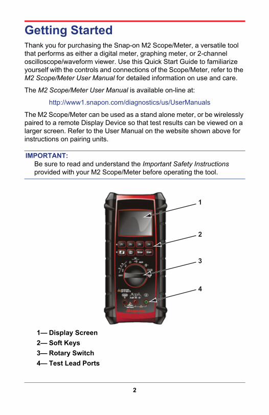
Getting StartedThank you for purchasing the Snap-on M2 Scope/Meter, a versatile tool that performs as either a digital meter, graphing meter, or 2-channel oscilloscope/waveform viewer. Use this Quick Start Guide to familiarize yourself with the controls and connections of the Scope/Meter, refer to the M2 Scope/Meter User Manual for detailed information on use and care.
The M2 Scope/Meter User Manual is available on-line at:
http://www1.snapon.com/diagnostics/us/UserManuals
The M2 Scope/Meter can be used as a stand alone meter, or be wirelessly paired to a remote Display Device so that test results can be viewed on a larger screen. Refer to the User Manual on the website shown above for instructions on pairing units.
IMPORTANT:Be sure to read and understand the Important Safety Instructions provided with your M2 Scope/Meter before operating the tool.
1— Display Screen2— Soft Keys3— Rotary Switch4— Test Lead Ports
1
2
3
4
2
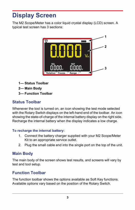
Display ScreenThe M2 Scope/Meter has a color liquid crystal display (LCD) screen. A typical test screen has 3 sections:
1— Status Toolbar2— Main Body3— Function Toolbar
Status ToolbarWhenever the tool is turned on, an icon showing the test mode selected with the Rotary Switch displays on the left-hand end of the toolbar. An icon showing the state-of-charge of the internal battery display on the right side. Recharge the internal battery when the display indicates a low charge.
To recharge the internal battery:1. Connect the battery charger supplied with your M2 Scope/Meter
Kit to an appropriate service outlet.2. Plug the small cable end into the single port on the top of the unit.
Main BodyThe main body of the screen shows test results, and screens will vary by test and tool setup.
Function ToolbarThe function toolbar shows the options available as Soft Key functions. Available options vary based on the position of the Rotary Switch.
FreezeRelative RangeF1 F2 F3 F4
VDC
REL REF
VV
1
2
3
3

Soft KeysThe eight soft keys located above the Rotary Switch are used to initiate a variety of additional functions while performing meter tests. Short presses (momentary) and long (press and hold) presses of the soft keys have different results. Soft key operations are unique when in the oscilloscope mode, see “Oscilloscope/Waveform Viewer” on page 6 for details. The table below briefly describes soft key operations:
Table 1-1 Soft Key options
Name Key Description Mode
F1A short press switches the displayed value to a relative reading, a long press returns the display to a normal reading.
Volts DC, Volts AC, Resistance, Auxiliary
F2A short press freezes, or pauses, the data being displayed. A second press returns the display to live data.
All except Continuity and Diode Check
F3Changes the measurement range when in Volts DC, Volts AC, Resistance, Auxiliary, capacitance, graphing or scope modes.
Volts DC, Volts AC, Resistance, Capacitance
F4Available only in graph and oscilloscope modes, this soft key is used to change the time base.
Waveform Viewer
S
A short press of the Special Functions key switches between functions (Hz, Pw, etc.), a long press returns to the original setting. Available functions vary by test mode.
Volts DC, Volts AC, Waveform Viewer
Min/Max
The Min/Max key displays the minimum and maximum sampled signal values along with the current value. A short press resets the readings, a long press cancels.
All except Continuity and Diode Check, Capacitance
Range
Short presses of the Range key switches the precision of the displayed value incrementally. A long press returns the value to Auto ranging.
All
Graph
A short press of the Graph key switches the display from a digital readout to a histogram, or graph. A long press switches the display back to digital.
Volts DC, Volts AC, Auxiliary
4

Rotary SwitchThe Rotary Switch is the main control for the M2 Scope/Meter. It configures the meter for the type of test, or function, to be performed. Each function is indicated by a graphic icon, as explained in the table below:
Table 1-2 Rotary Switch options
Function Icon Description
OffSwitches power to the M2 Scope/Meter off. The switch should be in this position when the tool is not being used to prevent battery drain.
Volts DC
Measures direct current (DC) voltages within a range of zero to 1000 volts. This setting is also used to measure frequency (hertz), duty cycle (%), time period (cycle, ms), and pulse width (Pw).
Volts AC
Measures alternating current (AC) voltages within a range of zero to 1000 volts. This setting is also used to measure frequency (hertz), duty cycle (%), time period (cycle, ms), and pulse width (Pw).
Resistance Measures the DC resistance to current in ohms in a range of zero to open circuit (infinite).
Continuity/Diode Check
Performs dual tests; circuit continuity and diode test (forward drop). The “S” (special function) soft key switches between the two tests.
Auxiliary
Performs three auxiliary tests; current (amperes), pressure/vacuum, and temperature. Use the “S” (special functions) and “Range” soft keys to switch between the tests and output units. Pre-approved sensors must be used to take valid measurements.
Capacitance Measures capacitance in nanofarad (nF), millifarad (mF), and microfarad (μF).
Oscilloscope(Waveform Viewer)
Configures the M2 Scope/Meter to perform as an oscilloscope, or waveform viewer.
Remote Functions
Configures the M2 Scope/Meter to be operated through a remote Display Device. Readings are only shown on the Display Device screen. The controls on the front panel of the M2 Scope/Meter become inoperative when the rotary switch is in this position.
5

Oscilloscope/Waveform ViewerThe M2 Scope/Meter functions as a two-channel oscilloscope, or waveform viewer when the rotary switch is turned to the “scope” position.
Soft key functions are unique in oscilloscope mode.There are seven available setting ranges for the F2, F3, and F4 keys. Pressing F1 scrolls up through the list of settings, and pressing S scrolls down through the list. The F1 area on the screen shows which of the settings is currently active, refer to the M2 Scope/Meter User Manual for detailed descriptions.
DisplayIn the display mode the soft keys perform the following functions:
• F2—press to pauses data collection, press again to restore collection.• F3—advances up to the next available voltage scale.• F4—advances to the next time base. Press and hold to return to the
default setting.• Range—moves down through the list of available voltage scales.• Graph—moves down through the list of available time bases.
TriggerIn the trigger mode the soft keys perform the following functions:
• F2—switch the trigger between the rising (positive) and trailing (negative) edge of the waveform.
• F3—a short press incrementally increases the trigger voltage level. Press and hold to return to the default setting.
• F4—switches triggering between channels 1 (CH1) and 2 (CH2).• Range—short presses incrementally decrease the trigger voltage
level. Press and hold to return to the default setting.
Table 1-3 Scope Soft Key functions
Setting F1 Key S Key F2 Key F3 Key F4 KeyDisplay
Scroll Up
Scroll Down
Pause Scale TimeTrigger Slope Level ChannelPreset A GCI&S LF AC HF ACPreset B PCI&S LF DS HF DSSpecial Peak Invert CouplingPosition Move Ch1 Trace Move Ch2 Trace Not UsedChannel Display Ch1 Display Ch2 Select Channel
6

Preset A and Preset BInterpret Preset abbreviations in Table 1-3 as follows:
• GCI&S—ground controlled injectors and solenoids• LF AC—low frequency alternating current signals• HF AC—high frequency alternating current signals• PCI&S—power controlled injectors and solenoids• LF DS—low frequency digital signals• HF DS—high frequency digital signals
SpecialSpecial settings alter the way the trace is displayed. A short push of the F2, F3, or F4 key activates the indicated mode, a long push cancels the mode.
• F2—switches on the peak capture function, which allows you to see very fast signal transitions or glitches.
• F3—inverts, or switches, the polarity of the signal trace.• F4—switches the input to the meter from DC coupling (default) to AC
coupling. Use for viewing alternator ripple or fuel pump amperage.
PositionRepositions the baseline of the trace vertically on the screen:
• A short push of the F2 key moves the trace up incrementally.• A long push of the F2 key places the trace at the midpoint of the scale.• A short push of the Min/Max key moves the trace down incrementally.• A long push of the Min/Max key places the trace at 10% of the scale.• A short push of the F3 key moves the trace up incrementally.• A long push of the F3 key places the trace at the midpoint of the scale.• A short push of the Range key moves the trace down incrementally.• A long push of the Range key places the trace at 10% of the scale.
ChannelThe channel selection switches the trace on and off. The F2 key controls the channel 1 trace and the F3 key controls the channel 2 trace, the F4 key switches the selected channel.
Pressing the key the first time turns the channel “off” and the sweep signal is removed from the display. Pressing the key a second time turn the channel back “on” and the sweep signal is visible.
7

Test Leads and PortsTest lead ports are color-coded to the test leads and accessories provided with your kit for easy identification and connection.
1— Common2— Channel 13— Channel 2
When removing leads from their sockets, do not pull on the wire because it can damage the leads. Pull on the plug.
Three insulated alligator clips that attach to the test leads are included. The insulator boots are colored to match each test lead.
To install an alligator clip:1. Remove the collar from the probe by threading it counterclockwise
off of the probe tip.Store the collar in a safe place while not in use.
2. Thread the alligator clip onto the end of the probe.
3
2
1
8