dual laminate pipe and fittings solutions alcohols 4.6 chemical resistance: pvc/frp’s vinyl ester...
TRANSCRIPT
1
Seamless PVC/FRP SpecificationsSeamless PVC/FRP Dual Laminate Pipe and Fittings
ITEM DIMENSION TOLERANCESPipe Spools Length ± 1/8”
Bolt hole alignment ± 1/16”Flange alignment ± 1/32” (1” thru 4”)(with pipe centerline) ± 3/64” (6” >)
Flanges All dimensions except thickness
ASME B16.5
Fittings Face to centerline ± 1/8”Flange alignment ±1/32” (1” thru 4”)(with pipe centerline) ± 3/64” (6” >)
I.D. Radius 1/4” ± 1/16”Flanges
3.4 Dimensional drawings of standard PVC/FRP products:
- Piping Specification - Flange Dimensions - Pipe Dimensions. Pipe and Fittings Weights (1 ½” Ø thru 12” Ø) - Pipe Dimensions, Pipe and Fittings Weights (14” Ø thru 24” Ø) - Fitting Dimensions
NOTE: Non-Standard items will require customer-approved prints prior to fabrication.
4. APPLICATION AND OPERATIONAL PARAMETERS
4.1 PVC/FRP liner material is suitable for operating temperatures up to 170°F (77°C).
4.2 Pressure Ranges: PVC/FRP is suitable for continuous operation from full vacuum for 150 PSI for 1” diameter through 12” diameter and full vacuum to 100 PSI for 14” diameter through 24” diameter when operating within the temperature range specified in subsection 4.1
4.3 Continuous full vacuum services require a bonded flange.
4.4 Thermal Expansion: the Coefficient of Thermal expansion for PVC/FRP pipe is ~1.7 x 10⁻⁵in/in/°F when operating within the temperature range specified in subsection 4.1.
4.5 Chemical Resistance (liner): PVC/FRP’s liner is chemically inert to a broad range of commercial chemicals including the following:
1. SCOPE
This specification provides design information applicable to RPS Composites’ PVC/FRP piping products (seamless PVC/FRP dual laminate). Standard manufacturing specifications and dimensions are provided, however, custom specifications and designs can be tailored for unique requirements. Consult RPS Composites for more information.
2. MATERIALS
2.1 Liner: PVC liners are seamless. Only virgin PVC/FRP is used in the extrusion of liners. This resin meets the requirements of ASTM D-1784 and may include less than 1% inorganic pigment for identifi-cation. A partial list of the physical properties is below:
PROPERTY PVC VALUE TESTSpecific Gravity 1.38 ASTM D-792Tensile Strength 7,700 ASTM D-638
2.2 Bonding: Bonding of the PVC liner to the FRP structure is accom-plished through a proprietary process resulting in a chemical linking of structure to liner. The shear strength of the bond as measured per BS 4994 B-10 is 1015 PSI minimum.
2.3 Outer Structure: The bonded PVC liner is reinforced by filament wound (standard) or hand lay-up vinyl ester fiberglass structure yielding a totally bonded dual laminate. Hand lay-up construction when performed is per ASTM C582 Type II, Grade V. Only premium grade vinyl ester resins are used with glass reinforcement and UV stabilized exterior gel coat.
3. DESIGN AND FABRICATION DETAILS
3.1 All dimensional drawings included in this specification are suitable for use in the design of pipe systems. Tolerances in subparagraph 3.3 should be considered in design.
3.2 Flanges for pipe spools and fittings shall have an internal diameter, outer diameter bolt circle, hole diameter and number of boltholes in accordance with ASME B16.5 Class 150, unless otherwise specified.
3.3 Pipe and fittings fabrication tolerances are as follows:
2
Seamless PVC/FRP Specifications
Mineral acids Alkalies Salt solutions Alcohols
4.6 Chemical Resistance: PVC/FRP’s vinyl ester structure is inherently corrosion resistant. This typically allows open air or direct burial installation in harsh chemical environments with no additional protection. Gel coat exterior contains UV stabilizer. Fire retardant protection is available. For specific environments, consult RPS Composites.
4.7 Gas Permeation: RPS’ bonding technology eliminates air gaps between the PVC liner and vinyl ester structure. If a gas permeates the PVC liner, it is conducted directly to the vinyl-ester structure, which permeates at a higher rate than the PVC liner. This elimi-nates condensation between the liner and structure which is a common problem in lined steel pipe. Since these gases/liquids are not trapped between PVC/FRP’s liner and vinyl ester structure, no weep holes are required and internal corrosion of the structure is eliminated.
4.8 Insulation Qualities: PVC/FRP’s vinyl ester structure yields a heat conduction factor (k) of ~ 1.5 Btu*in/FT2/hr/°F. Check dimensional data for structure thickness. If additional thermal protection is necessary, contact RPS for details on Heat Traceable, Pre-insulated and/or Dual Contained PVC/FRP Systems.
4.9 Heat Tracing: PVC/FRP’s vinyl ester structure is capable of handling dry heat trace applications up to 180°F. On pre-insulated PVC/FRP systems, channels can be provided for heat trace wire. Contact RPS Composites for more information.
5. INSPECTION
5.1 All extruded liners are inspected prior to fabrication for pinholes, cracks, gauges, nicks, or inclusion of foreign particles.
5.2 Completed fittings shall be subjected to a 10,000-volt, non-de-structive, electrostatic spark test to detect pinholes. This test is to be performed by RPS Composites only with properly controlled voltage and procedures.
6. HANDLING AND SHIPPING
6.1 The gasket face of each spool or fitting shall be protected by end plates or other suitable protective means.
6.2 All spools and fittings shall be packed to provide necessary protection during handling, shipping, and storage.
7. INSTALLATION AND ASSEMBLY DATA
7.1 Supports: Hangers and supports may be ordered from RPS Composites or supplied by customer. Supports should have a minimum 1/8” thick rubber liner. Verify actual pipe outside diameter before ordering supports.
7.2 Support spacing: Support spacing can vary depending on actual service conditions and piping configuration. Supports for piping with the longitudinal axis in approximately a horizontal position shall be spaced to prevent excessive sag, bending and shear stresses in the piping with special consideration given where components such as flanges and valves impose concentrated loads. Where calculations are not made, suggested maximum spacing of supports are given in the table on page 3. Vertical supports shall be spaced to prevent the pipe from being over stressed from the combination of all loading effects (ANSI B31.1). In additional, Appendix III, Non-Mandatory Rules for Nonmetallic Piping of ANSI B31.1 should be taken into consideration. The values listed in the table are based on maximum operating conditions but do not apply where span calculations are made or where there are concentrated loads between supports such as flanges, valves, specialties, etc.
7.3 Gaskets: GASKET MUST BE USED IN RPS’ PVC/FRP PIPING SYSTEM. Recommended gaskets are elastomeric materials of 55-70 durometer suitable for the intended chemical service.
7.4 Bolts: Size and grade per ASME specification. SAE washers shall be used on all flanged fittings. Standard hex nuts shall be used on fittings 1 ½” diameter through 6” diameter. Fittings 8” and up can accommodate heavy hex nuts if preferred.
7.5 Torquing Procedure: The following procedure will insure that the necessary forces are applied to seat Envelon Style 3565 gaskets using the torque values of subsection 7.6. When other gasket materials are used, they should not exceed 70 durometer to assure proper seating.
A. Lubricate all bolts and nuts with a suitable lubricant, finger tighten all nuts.
B. With torque wrench, using a criss-cross method, tighten each bolt until appropriate torque values are met as specified in the Maximum Bolt Torque table under subsection 7.6.
C. After 24-30 hours, a temperature cycle, or a pressure cycle, torque for each bolt shall be checked. Those below the minimum are to be re-torqued to the values listed in subsection 7.6.
3
Seamless PVC/FRP Specifications
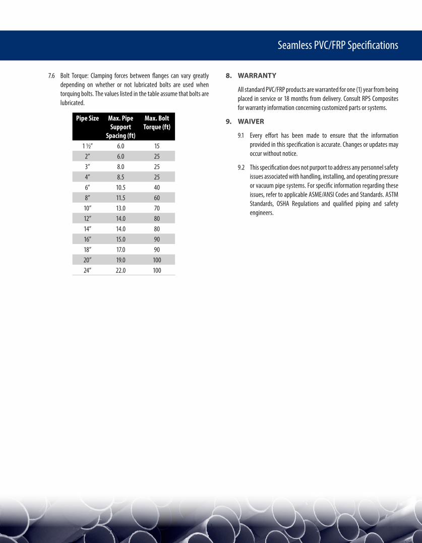
7.6 Bolt Torque: Clamping forces between flanges can vary greatly depending on whether or not lubricated bolts are used when torquing bolts. The values listed in the table assume that bolts are lubricated.
Pipe Size Max. Pipe Support
Spacing (ft)
Max. Bolt Torque (ft)
1 ½” 6.0 152” 6.0 253” 8.0 254” 8.5 256” 10.5 408” 11.5 60
10” 13.0 7012” 14.0 8014” 14.0 8016” 15.0 9018” 17.0 9020” 19.0 10024” 22.0 100
8. WARRANTY
All standard PVC/FRP products are warranted for one (1) year from being placed in service or 18 months from delivery. Consult RPS Composites for warranty information concerning customized parts or systems.
9. WAIVER
9.1 Every effort has been made to ensure that the information provided in this specification is accurate. Changes or updates may occur without notice.
9.2 This specification does not purport to address any personnel safety issues associated with handling, installing, and operating pressure or vacuum pipe systems. For specific information regarding these issues, refer to applicable ASME/ANSI Codes and Standards. ASTM Standards, OSHA Regulations and qualified piping and safety engineers.

4
Seamless PVC/FRP Specifications
SERVICES:
As specified by user or RPS Composites
MATERIAL:
PVC/FRP as provided by RPS Composites dual laminate, seamless PVC liner with bonded fiberglass reinforced vinyl Ester structure.
SIZE/RATING:
1 ½” – 12” Full Vacuum 150 psi 0-170°F
14” – 24” Full Vacuum 100 psi 0-170°F
PIPE:
150# flanges spools 20’-0” standard length
FITTINGS:
Flanged, ASME B16.5 Class 150 Dimensions.
BRANCH CONNECTIONS:
Use full size or reducing tees
INSTRUMENT CONNECTIONS:
Use tee
FLANGES:
All flanges drilling patter per ASME B16.5 Class 150 dimensions (except thickness)
• Fixed: Full face flanges to be fabricated on pipe spools by pipe manufacturer. Pipe liner to be flared over face of flange to inside of bolt holes.
• Lap Joint: Stub end with loose ring fabricated on pipe by pipe manufacturer. Pipe liner to be flared over stub face to outside diameter of stub.
• Blinds: Flat faced FRP with PVC liner bonded to face.
GASKETS:
Gasket material suitable for intended service conditions. Consult gasket manufacturer for recommendation. GarlockTM, EnvelonTM 3565 gasket material is comparable to PVC/FRP liner material. Ring type or full face. 1/16” min. – 1/8” max. thick.
BOLTING:
Alloy steel machine bolts or studs with (2) SAE washers and standard nuts 1 ½” thru 6”Ø if preferred.
WELDING:
Assembly of PVC/FRP piping components is accomplished by welding the liner sections and then laminating the components together. The liner weld is accomplished by solvent, hot plate, or hot gas welding. Welds are spark tested to detect pinholes prior to laminating.
NOTES:
1. Instrument connections (including vents and drains) may be fabricated directly into pipe spools minimum size is 1” diameter.
2. Piping may be shop fabricated or field welded by manufacturer
3. One inch (1”) piping is available in short spools only (24” or less).
Piping Specification
5
Seamless PVC/FRP Specifications
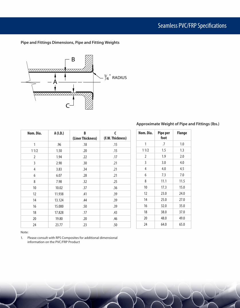
Pipe and Fittings Dimensions, Pipe and Fitting Weights
A
B
C
14 RADIUS"
Nom. Dia. A (I.D.) B (Liner Thickness)
C (F.W. Thickness)
1 .96 .18 .151 1/2 1.50 .20 .15
2 1.94 .22 .173 2.90 .30 .214 3.83 .34 .216 6.07 .28 .218 7.98 .32 .25
10 10.02 .37 .3612 11.938 .41 .3914 13.124 .44 .3916 15.000 .50 .3918 17.828 .17 .4320 19.80 .20 .4624 23.77 .23 .50
Approximate Weight of Pipe and Fittings (lbs.)
Nom. Dia. Pipe per foot
Flange
1 .7 1.01 1/2 1.5 1.3
2 1.9 2.03 3.0 4.04 4.0 4.56 7.3 7.08 11.1 11.5
10 17.3 15.012 23.0 24.014 25.0 27.016 32.0 35.018 38.0 37.020 48.0 49.024 64.0 65.0
Note:
1. Please consult with RPS Composites for additional dimensional information on the PVC/FRP Product
6
Seamless PVC/FRP Specifications
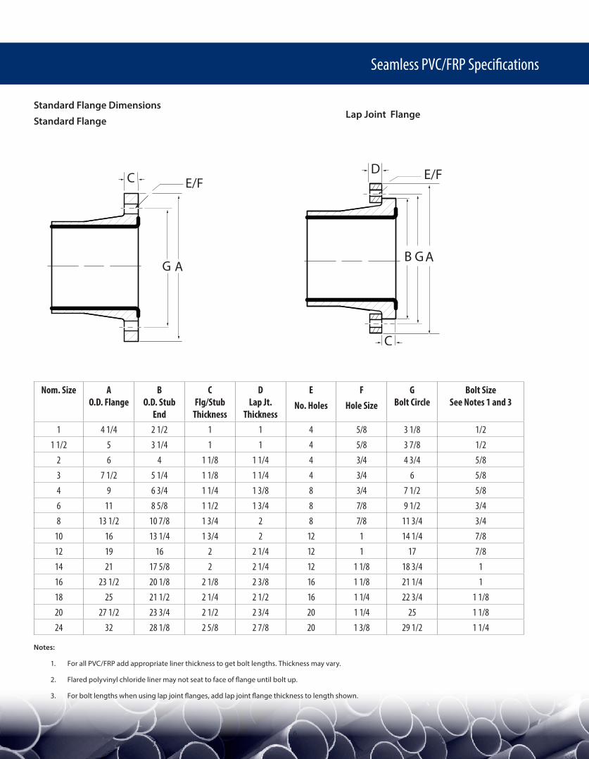
Standard Flange Dimensions
Standard FlangeLap Joint Flange
Nom. Size AO.D. Flange
BO.D. Stub
End
CFlg/Stub
Thickness
DLap Jt.
Thickness
ENo. Holes
FHole Size
GBolt Circle
Bolt SizeSee Notes 1 and 3
1 4 1/4 2 1/2 1 1 4 5/8 3 1/8 1/21 1/2 5 3 1/4 1 1 4 5/8 3 7/8 1/2
2 6 4 1 1/8 1 1/4 4 3/4 4 3/4 5/83 7 1/2 5 1/4 1 1/8 1 1/4 4 3/4 6 5/84 9 6 3/4 1 1/4 1 3/8 8 3/4 7 1/2 5/86 11 8 5/8 1 1/2 1 3/4 8 7/8 9 1/2 3/48 13 1/2 10 7/8 1 3/4 2 8 7/8 11 3/4 3/4
10 16 13 1/4 1 3/4 2 12 1 14 1/4 7/812 19 16 2 2 1/4 12 1 17 7/814 21 17 5/8 2 2 1/4 12 1 1/8 18 3/4 116 23 1/2 20 1/8 2 1/8 2 3/8 16 1 1/8 21 1/4 118 25 21 1/2 2 1/4 2 1/2 16 1 1/4 22 3/4 1 1/820 27 1/2 23 3/4 2 1/2 2 3/4 20 1 1/4 25 1 1/824 32 28 1/8 2 5/8 2 7/8 20 1 3/8 29 1/2 1 1/4
Notes:
1. For all PVC/FRP add appropriate liner thickness to get bolt lengths. Thickness may vary.
2. Flared polyvinyl chloride liner may not seat to face of flange until bolt up.
3. For bolt lengths when using lap joint flanges, add lap joint flange thickness to length shown.
C
AG
E/F
GB
E/F
A
D
C
7
Seamless PVC/FRP Specifications
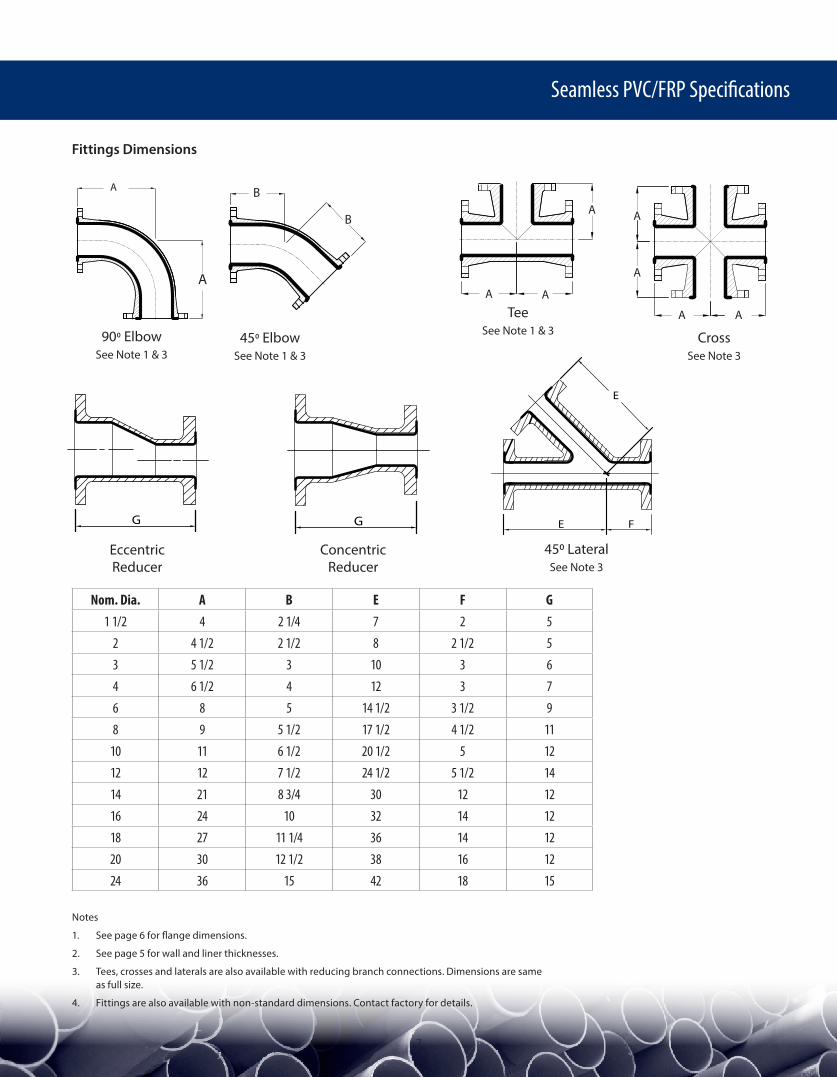
Fittings Dimensions
Nom. Dia. A B E F G1 1/2 4 2 1/4 7 2 5
2 4 1/2 2 1/2 8 2 1/2 53 5 1/2 3 10 3 64 6 1/2 4 12 3 76 8 5 14 1/2 3 1/2 98 9 5 1/2 17 1/2 4 1/2 11
10 11 6 1/2 20 1/2 5 1212 12 7 1/2 24 1/2 5 1/2 1414 21 8 3/4 30 12 1216 24 10 32 14 1218 27 11 1/4 36 14 1220 30 12 1/2 38 16 1224 36 15 42 18 15
Notes
1. See page 6 for flange dimensions.
2. See page 5 for wall and liner thicknesses.
3. Tees, crosses and laterals are also available with reducing branch connections. Dimensions are same as full size.
4. Fittings are also available with non-standard dimensions. Contact factory for details.
FE
E
G G
90o ElbowSee Note 1 & 3
45o ElbowSee Note 1 & 3
TeeSee Note 1 & 3 Cross
See Note 3
450 LateralSee Note 3
Eccentric Reducer
Concentric Reducer
B
B
A
AA
A
AA
A
A
A A
8
Seamless PVC/FRP Specifications
RPS Composites Inc.8375 Zeigler Blvd.Mobile, AL 36689Tel: (251) 445-4411Fax: (251) 633-3318www.rpscomposites.com
Seamless PVC/FRP DL Pipe and Fittings - Jan 2016