copy of rm riley maintenance manual 1!! 2 litre and 2~ litre issued by iiiley motors limited p op e...
TRANSCRIPT

WORKSHOPWORKSHOPWORKSHOPWORKSHOP
MANUALMANUALMANUALMANUAL
1½ LITRE1½ LITRE1½ LITRE1½ LITRE
andandandand
2½ LITRE2½ LITRE2½ LITRE2½ LITRE

MANUAL
1!!2 LITREand
2~ LITRE
Issued by
IIILEY MOTORS LIMITEDP op e ors MORRIS MOTORS LIMITED
ABINGDO¶ - BERKSHIRE - ENGLAND
Sole Exporters
NUF FIELD EXPORTS LIMITEDProprietors MORRIS MOTORS LIMITED
COWLEY - OXFORD - ENGLAND
WORKSHOP
NOTE
Amendments to the instructions given in this manual are onlymade by the issue of revised sheets, or by additional sheets forinclusion at the end of each section.
It is therefore of the utmost importance to refer to the end ofeach of the sections for the latest instructions before carryingout any work on tie vehicle.
I{ and 2+ Litre. Issue 3 (H & E) 87302—5154

THIS MANUAL HAS BEEN REPRODUCED BY KIND PERMISSION OF
AUSTIN-MORRIS DIVISION
BRITISH LEYLAND MOTOR CORPORATION
COWLEY. OXFORD
THIS EDITION DESIGNED BY J. A. BYRON FOR THE RILEY RM CLUB
AND THE EXCLUSIVE USE OF ITS MEMBERS.
PRINTED IN ENGLAND 1979


CONTENTSSection
General Data
General Information
Maintenance Attention (Free and Periodical)
Frost Precautions
General Data (Series RME and RMF)
Engine (24 litre) ... ... ...
Engine (14 litre) ... ... ...
Engine (24 litre, Series RMF) ...
Fuel System (24 litre) ... ...
Fuel System (14 litre) ... ...
Ignition System (14 and 24 litre) ... ...
Cooling System (14 and 24 litre) ... ...
Clutch (14 and 24 litre) ... ... ...
Gearbox (14 and 24 litre) ... ... ...
Intermediate Driving Shaft (14 and 24 litre)
Intermediate Driving Shaft and Propeller Shaft (Series
Rear Axle (14 and 24 litre) ... ...
Rear Axle (Series RME and RMF) ...
Rear Road Springs (14 and 24 litre) ...
Front Suspension (14 and 24 litre) ...
Hydrauli.c Dampers (14 and 24 litre) ...
Braking System (14 and 24 litre) ... ...
Braking System (Series RME and RMF)
Electrical Equipment (14 and 24 litre) ...
Wheels and Tyres (14 and 24 litre) ...
Lubrication (14 and 24 litre) ... ...
Special Tools (14 and 24 litre) ... ...
Body (14 and 24 litre) ... ... ...
RME and RMF)
A
AA
AAA
B
BB
C
D
E
F
G
GG
H
HH
J
K
L
M
MM
N
0
P
Q
R
3Riley I~ and 24~ Litre. Issue 3 (H & E) 87302—5/54

GENERAL DATA(I~ LITRE)
ENGINENumber of cylindersCapacity ...
B.H.P. ... ...
Bore ... ...
Stroke ... ...
Compression ratioSystem of coolingRadiator hose, top (outlet)Radiator hose—pump to head
Radiator hose—radiator to pump
First oversize boreSecond oversize bore (max~)Firing orderPiston clearance, topPiston clearance, bottomRing gap ...
Number of compression ringsWidth of compression ringsNumber of oil control ringsWidth of oil control ringsOil pressure release valveGudgeon pin type
Gudgeon pin diameter
Fit in piston ...
Fit in connecting rodGudgeon pin—oversizeCrankpin diameter—standardCrankpin, minimum diameter for regrindConnecting rod centres...Connecting rod—~type of bearingConnecting rod—side clearanceConnecting rod—diametrical clearanceNumber of crankshaft bearingsType of main bearingsStandard main journal diameter
Main JournalsFirst regrind diameterSecond regrind diameter (minimum)
Main bearings—end clearanceMain bearings—diametrical clearance
Crankshaft end thrustNumber of camshaft bearingsType of camshaft bearings
Four.1496 c.c. (91.28 cu. in.).54 at 4,500 r.p.m.69 mm. (2.7165 in.).100 mm. (3.937 in.).6~8 to I.Thermo-siphon, fan and pump.Pre-formed to fit thermostat.2 in. longx l.~ in. outside diameter (5.08 cm.x3~8I cm.).Inside diameter to fit tight over II in. (3.175 cm.)
diameter tube.2~ in. Iongx I~ in. outside diameter (6.67 cm.x4~I3 cm.).Inside diameter to be a push fit on I~ in. (3.175 cm.)
diameter tube.-j-~020 in. (±~5mm.). Bore 2~7365 in. (69.5 mm.).+040 in. (±l~0mm.). Bore 2~7565 in. (70 mm.).1,2,4,3.~0024in. to ~0034in. (.061 mm. to ~086mm.).0012 in. to ~003in. (.03 mm. to ~076mm.).
~006in. to •010 in. (.152 mm. to ~254mm.).Three..079 in. (2 mm.).One.~ in. (3.969 mm.).50 lb./sq. in. (3.5 kg./cm.2).Floating.
~75Oin ~+000 in.~0003 in.
±~OO0mm.—~006 mm.
Hard push fit at 70~ C.Push.±~002in. (.05 I mm.).b875 in. (4.763 cm.).—040 in. (—1.0 mm.).8 in. (20.32 cm.).White metal direct.~002in. to ~004in. (.05 mm. to •10 mm.).~00l5in. (.038 mm.).Three.Thick white-metal lined.Front and rear I~75 in~ (4.445 cm.).Centre 275 in. (6.985 cm.).
—~020 in. (.508 mm.).~040in(l.l mm.).•004 in. to ~006in. (.1 mm. to ~l5 mm.).~0025in. (.060 mm.) centre.•0015 in. (.040 mm.) front and rear.On rear bearing.Three.Bronze at front and rear. Centre bearing is machined
in block.
4 Riley 1+ and 2j Litre, Issue 3 (H & E) 87302—5/54

(1+ LITRE)
GEN ERAL DATA—continued
Camshaft bearing clearanceCamshaft end thrustCamshaft drive
Valve timing
Exhaust valve throat diameterExhaust valve diameter
Inlet valve throat diameterInlet valve diameter
Valve seat angleTappet typeValve lift, inletValve lift, exhaustInlet valve opensInlet valve closesExhaust valve opensExhaust valve closesValve spring, shutValve spring, openInlet valve opens—piston traverse
Inlet valve working clearance
Exhaust valve working clearance
Valve guides
.0025 in. (.060 mm.).Taken on front bearing.By duplex roller chain.Crankshaft keyway vertical.
bright links on chain.I ~- in. (33.3 mm.).Head l-j~ in. (36.5 mm.).Stem -~ in. (7.94 mm.).I ~ in. (33.3 mm.).Head lj~ in. (36.5 mm.).Stem ~ in. (7.94 mm.).45O~
Mushroom..289 in. (.734 mm.).~289in. (.734 mm.).
before T.D.C.I 480 after B.D.C.480 before B.D.C.200 after T.D.C.56 lb. (25.40 kg.).74 lb. (33.566 kg.).
RME ~0l837in. (.467 mm.)before T.D.C.
.015 in. (.38 mm.).Hot engine.
•0l5 in. (.38 mm.).
Hot engine.Removable.
“T “s on chain wheels and
EarlyModels
r 90 before T.D.C.450 after B.D.C.
560 before B.D.C.20~ after T.D.C.575 lb. (26.082 kg.).73 lb. (33.112 kg.).
•o3Q~4 in. (.76 mm.)before T.D.C.
.QQ3 in. (.076 mm.).Hot engine.
.004 in. (10 mm.).
L Hot engine.
FUEL SYSTEMPetrol tank levelFuel deliveryCarburetterCarburetter needle
CLUTCHTypeFacing
GEARBOXSynchromeshRatios
Overall
Gearbox
Electric gauge on panel.A.C. mechanical pump type “U.’,S.U. horizontal H—2.No. 3 Standard. Rich—BY; Weak—V2.
Borg and Beck 8 in. (20.32 cm.) diameter. A6—G type.Ferodo RYZ.
Second, third and top.
TopThird
RME SecondFirstReverseTopThirdSecondFirstReverse
5~l25to I.7•585 to I.
ll~736to I.20~372to I.20.372 to I.I tol.1.48 to I.
r 4~89to I.
Early ll~2 to I.[7~23 to I.Models l9~42to I.
l9~42to I.
2~29 to I.3.975 to I.3.975 to I.
5Riley Ij and 2+ Litre. Issue 3 (H & E) 87302—5/54
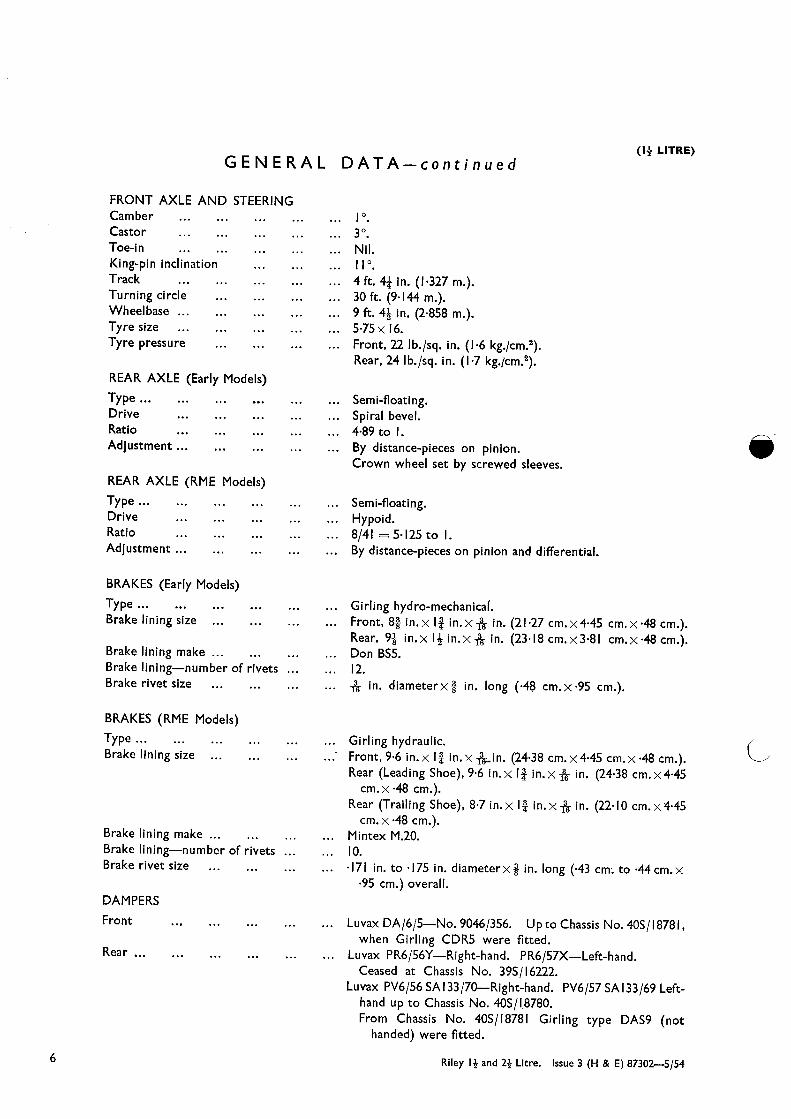
(1+ LITRE)GENERAL DATA—continued
FRONT AXLE AND STEERINGCamberCastorToe-inKing-pin inclinationTrackTurning circleWheelbaseTyre sizeTyre pressure
REAR AXLE (Early Models)
TypeDriveRatioAdjustment
I 0
30
Nil.II 0
4 ft. 4j in. (1.327 in.).
30 ft (9.144 in.).
9 ft. 4~ in. (2.858 in.).
5~75x 16.Front, 22 lb./sq. in. (1.6 kg./cm.2).Rear, 24 lb./sq. in. (1.7 kg./cm.2).
Semi-floating.Spiral bevel.489to I.By distance-pieces on pinion.Crown wheel set by screwed sleeves.
REAR AXLE (RME Models)
Semi-floating.Hypoid.
8/41 ~zo 5.125 to I.By distance-pieces on pinion and differential.
BRAKES (Early Models)
Type ... ...
Brake lining size
Brake lining make ...
Brake lining—number of rivetsBrake rivet size ...
Girling hydro-mechanical.Front, 8~ in.x I~ in.x~ in. (21.27 cm.x4~45 cm.x~48 cm.).Rear, 9~ in.x II in.x~ in. (23.18 cm.x3~8l cm.x~48 cm.).Don B55.12.~- in. diameterx.~ in. long (.48 cm.x~95 cm.).
BRAKES (RME Models)
TypeBrake lining size
Brake lining make ...
Brake lining—number of rivetsBrake rivet size ...
DAMPERS
Front
Rear
6
Girling hydraulic.Front, 9~6 in.x l~ in.x ~ in. (24.38 cm.x4~45 cm.x~48 cm.).Rear (Leading Shoe), 9.6 in.x 1j in.xj~ in. (24.38 cm.x4~45
cm.x~48 cm.).Rear (Trailing Shoe), 8~7 in.x I~ in.x~ in. (22.10 cm.x4~45
cm. x ~48cm.).Mintex M.20.10.~l7lin. to ~l75in. diameterx~ in. long (.43 cm. to 44cm.x
~95cm.) overall.
Luvax DA/6/5—No. 9046/356. Upto Chassis No. 40S/18781,when Girling CDR5 were fitted.
Luvax PR6/56Y—Right-hand. PR6/57X—Left-hand.Ceased at Chassis No. 39S116222.
Luvax PV6/56 5A133/70—Right-hand. PV6/57 5A133/69 Left-hand up to Chassis No. 40S/18780.From Chassis No. 40S/18781 Girling type DAS9 (not
handed) were fitted.
TypeDriveRatioAdjustment
Riley 1+ and 2+ Litre. Issue 3 (H & E) 87302—5/54
(I{ LITRE)
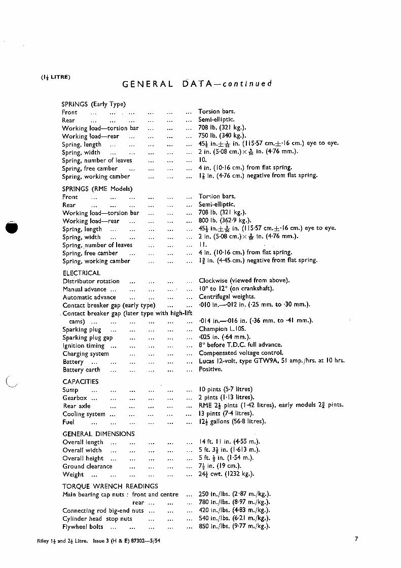
GENERAL
SPRINGS (Early Type)Front ...
RearWorking load—torsion barWorking load—rearSpring, lengthSpring, widthSpring, number of leavesSpring, free camberSpring, working camber
SPRINGS (RME Models)Front ...
Rear ...
Working load—torsion barWorking load—rearSpring, lengthSpring, widthSpring. number of leavesSpring, free camberSpring, working camber
ELECTRICALDistributor rotationManual advanceAutomatic advanceContact breaker gap (early type)Contact breaker gap (later
cams) ...
Sparking plugSparking plug gapIgnition timingCharging systemBattery ..
Battery earth
CAPACITI ESSumpGearboxRear axleCooling systemFuel
GENERAL DIMENSIONSOverall lengthOverall widthOverall heightGround clearanceWeight ...
TORQUE WRENCH READINGSMain bearing cap nuts front and
rearConnecting rod big-end nutsCylinder head stop nutsFlywheel bolts
type with high-lift
DATA—continued
Torsion bars.Semi-elliptic.708 lb. (321 kg.).750 lb. (340 kg.).45~ in.±.1
1~in. (115.57 cm.±16cm.) eye to eye.2 in. (5.08 cm.)x~ in. (4.76 mm.).10.4 in. (10.16 cm.) from flat spring.1k in. (4.76 cm.) negative from flat spring.
Torcion bars.Semi-elliptic.708 lb. (321 kg.).800 lb. (362.9 kg.).45k in.±* in. (I l5~57 cm.A~I6 cm.) eye to eye.2 in. (5.08 cm.)x~- in. (4.76 mm.).II.4 in. (10.16cm.) from flat spring.l~ in. (4.45cm.) negative from flat spring.
Clockwise (viewed from above).100 to 120 (on crankshaft).Centrifugal weights..010 in.—~0l2 in. (.25 mm. to .30 mm.).
•014 in.—~Ol6 in. (.36 mm. to .41 mm.).
Champion L.l0S..025 in. (.64 mm.).80 before T.D.C. full advance.Compensated voltage control.Lucas 12-volt, type GTW9A, SI amp.Ihrs. at 10 hrs.Positive.
10 pints (5.7 litres)2 pints (1.13 litres).RME 2k pints (1.42 litres), early models 2k pints.13 pints (7.4 litres).12k gallons (56.8 litres).
14 ft. II in. (4.55 in.).
5 ft. 3k in. (1.613 in.).
5 ft. k in. (1.54 in.).
7j in. (19 cm.).24~ cwt. (1232 kg.).
centre ... 250 in./lbs. (2~87 m./kg.).780 in./Ibs. (8.97 m./kg.).420 in./lbs. (4.83 m./kg.).540 in./lbs. (6.21 m./kg.).850 in./lbs. (9.77 m.Ikg.).
Riley 1+ and 2+ Litre. Issue 3 (H & E) 87302—5/54 7

GENERAL DATA(2~ LITRE)
ENGINENumber of cylindersCapacityB.H.P.BoreStrokeCompression ratioSystem of coolingRadiator hose top (outlet)Radiator hose diameter—radiator to pumpRadiator hose diameter—pump to headRadiator hose top (outlet)
Radiator hose (RMF)—radiator to headFirst oversize boreSecond oversize bore (max.)Firing orderPiston clearance, topPiston clearance, bottomRing gap ...
Number of compression ringsWidth of compression ringsNumber of oil control ringsWidth of oil control ringsOil pressure release valve operates
Gudgeon pin type ... ...
Gudgeon pin diameter ... ...
Fit in piston ... ... ...
Fit in connecting rod ... ...
Gudgeon pin oversizes ... ...
Crankpin diameter (standard) ...
Crankpin minimum diameter for regrindConnecting rod—length between centresConnecting rod—type of bearing (engines
prior to No. RMB21945) ...
Connecting rod—type of bearing (enginesfrom No. RMB2/945 onwards)
Connecting rod—side clearanceConnecting rod—diametrical clearanceNumber of crankshaft bearingsType of main bearingsStandard main journal diameterMain journals
First regrind diameterSecond regrind diameter (minimum)
Main bearings—length ...
Main bearings—end clearanceMain bearings—diametrical clearanceCrankshaft—end thrust onNumber of camshaft bearings
Early models.
Four.2443 c.c. (149 cu. in.).100 at 4,400 r.p.m.805 mm. (3.169 in.).120 mm. (4.724 in.).RMF 6~6 to I. Early models 6~8 to I.Pump, thermo-siphon and fan.Pre-formed to fit thermostat.
in. (3 1.7 mm.). Iin. (3 1.7 mm.).l~ in. (34.9 mm.), internal dia. x6~ in. (16.8 cm.) long.
RMF models.l~ in. (31.7 mm.), internal dia. x2~ in. (66.7 mm.) long~-I-~020 in. (.5 mm.). Bore size 3~l89 in. (81 mm.).+~040 in. (1.0 mm.). Bore size 3~209 in. (81.5 mm.).1,2,4,3.~002in. to ~0033in. (.05 mm. to ~084mm.).~00l8in. to ~0026in. (.046 mm. to ~066mm.).•008 in.—~0l2 in. (.2 mm.—3 mm.).Two.~0927in. to ~0937in. (2.35 mm. to 2~38 mm.).Two.•1565 in. to ~l575in. (3.88 mm. to 3~90 mm.).60 lb./sq. in. (4.2 kg./cm.2). RMF 50 lb./sq. in. (3.5
kg./cm.2).Floating.
~866in. (22 mm.).Hard push at 7Q0 C.Push.±~002in. (.05 I mm.).2~362 in. (60 mm.).2~322 in. (58.98 mm.) (—.040 in. (1.0 mm.)).8~625 in. (21.91 cm.).
White-metal cast direct on rod.
Top half: lead-bronze. Lower half: steel-backed, white-metal lined.
~002in.—~008 in. (.05 mm.—’2 mm.).~00l5in. (.038 mm.).Three.Thick, white-metal lined, bronze shells.2~559 in. (65 mm.).
~020in. (.5 mm.).040 in. (1.1 mm.).1.938 in. (49.25 mm.) front and centre.2~7559 (70 mm.) rear.Zero to ~004in. (0 mm. to ~I0mm.).~00Iin. to ~003in. (.025 mm. to 075 mm.).Rear bearing (flanged both sides).Three.
8 Riley 1+ and 2+ Litre. Issue 3 (H & E) 87302—5/54

(2+ LITRE)
GENERAL
Type of camshaft bearingsCamshaft—bearing clearanceCamshaft—end thrust onCamshaft driveValve timing markings
Exhaust valve throat diameterExhaust valve diameter
Inlet valve throat diameterInlet valve diameter
Valve seat angleTappet typeValve lift inletValve lift exhaustInlet valve opensInlet valve closesExhaust valve opensExhaust valve closesValve spring—shutValve spring—openInlet valve opens—piston traverse
Inlet valve working clearance
Exhaust valve working clearance
Valve guides
FUEL SYSTEMFuel tank levelFuel deliveryCarburettersCarburetter needles
DATA—continued
Bronze bushes..0015 in. to .004 in. (.0375 mm. to .10 mm.).Front face of front bearings.Duplex roller chain.Crankshaft keyway vertical and marks on chain wheels
(bright links on chain on RMF).1.476 in. (37.49 mm.).Head 1.604 in. (40.7 mm.).Stem ~ in. (7.94 mm.).l~702 in. (43.15 mm.).Head, early models l~856 (47.14 mm.) ; RMF 1.830 in.
(46.48 mm.).Stem ~ in. (7.94 mm.).450
Hollow.~390in. (9.9 mm.).•390 in. (9.9 mm.).120 before T.D.C.
530 after B.D.C.550 before B.D.C.
200 after T.D.C.68~6 lb. (31.12 kg.).III lb. (50.35 kg.). Early.0657 in. (1.67 mm.) Models
before T.D.C.•0l I in. (.28 mm.).
Hot engine.•0ll in. (.28 mm.).
Hot engine.Renewable.
RMF
~l7O before T.D.C.430 after B.D.C.450 before B.D.C.
2O~ after T.D.C.64~5 lb. (29.26kg.).99~5 lb. (45.13 kg.).~l3084 in. (3.3mm)
before T.D.C.•003 in. (.076 mm.).
Hot engine.•004 in. (.1 mm.).
Hot engine.
Electric gauge on panel.
S.U. electric pump, Type L.S.U. horizontal, H4 (two).Normal—E.E.; Weak—E.M.; No rich setting is recom-
mended.
CLUTCHTypeFacing
GEARBOXSynchromeshRatios
Overall
Gearbox
Borg and Beck, l0/73C., 10 in. (25.4 cm.) diameter.Ferodo RYZ.
Second, third, top.
CFirst and reverse I4~949 to I.jSecond 8~835 to I.
RMF jThird 5•814to I.~Top 41 to I.
rFirst and reverse 3~646 to I.ISecond 2~I55to I.IThird l~4I8to I.~Top I tol.
l5~0 to I.Early j 8~86 to I.Models I 5•83 to I.
to I.
Riley 1+ and 2+ Litre. Issue 3 (H & E) 87302—5/54 9

(2+ LITRE)
GENERAL DATA—continued
FRONT AXLE AND STEERING
Camber ...
Castor angleToe-in ...
Swivel pin inclinationTyre sizeTyre pressures (all wheels)Wheel size
30
Nil.II6~00—l6.24 Ib./sq. in. (!.7 kg./cm.2).4~50x 16.
REAR AXLE (Early Type)
Type of axleType of driveRatioAdjustment
Semi-floating.Spiral bevel.37/9.By distance-pieces for pinion.Crown wheel set by screwed bearing housings.
REAR AXLE (RMF)
Type of axleType of driveRatioAdjustment
Semi-floating.Hypoid.41/10.By distance-pieces for pinion and crown wheel.
BRAKES (Early Types)
Type
Type of liningLining size
Up to Chassis No. 60S/6094Front and rear
From Chassis No. 60S/6095Front only. Rear as above
Size of rivets
Girling hydro-mechanical.12 in. dia. front and rear (30.48 cm.). To Chassis
No. 60S/6094.II in. dia. front only (27.94 cm.). From Chassis
No. 60S/6095 onwards.MintexM.14.LengthWidthThicknessNumber of rivetsLengthWidthThicknessN.umber of rivets
10k in. (26.67 cm.).I~ in. (4.21 cm.).~ in. (3.97 mm.).12.9j in. (25.1 cm.).2j in. (5.7 cm.).~ in. (.48 cm.).12.
in. dia.x-~- in. long (.48 cm.x•79 cm.).
BRAKES (RMF)
TypeType of liningLining size
Size of rivets
Girling hydraulic. II in. dia. front and rear (27.94 cm.).MintexM.21.Front: I0~43 in.x21 in.x~ in. (26.49 cm.x5~7cm.x
~48cm.).Rear (LeadingShoe) : 1043 in. x2Iin .x~- in. (26.49cm.x
5~7 cm. x A8 cm.).Rear (Trailing Shoe): 9~6 in. x2~ in. x ~ in. (24.38 cm. x
5~7 cm. x ~48cm.).Number of rivets : Twelve.a in. dia. x ~ in. long (.44 cm. x •91 cm.) (under head).
10 Riley I + and 2+ Litre. Issue 3 (H & E) 87302—5/54

(2+ LITRE)
GENERAL DATA—continued
SPRINGS
Type—front
Type—rearWorking load—front
Working load—rearLength—rear (flat)Width—rearNumber of leavesThickness of leavesCamber
Torsion bar.Semi-elliptic.850 lb. (389 kg.).800 lb. (362.9 kg.) at 1k in. (47.6 mm.) negative camber.45k in. (I 15.57cm.).2 in. (50.8 mm.).II (early models) ; 12 (RMF open propeller shaft).~ in. (4.76 mm.).Free : 4 in. (10.16 cm.).Working : 1k in. (44.45 mm.) negative (RMF models).
1k in. (47.6 mm.) negative (early models).
DAMPERS
Luvax DA/6/5—No. 9046/356.Changed at Chassis No. 60S/7791 to Girling CDR5.Luvax PR6/68Y—Right-hand ; PR6/69X—Left-hand.Ceased at Chassis No. 59S/4610.From Chassis Nos. 59S/4611 to 60S/7790.Luvax PV6/68, 5A133/72—Right-hand.
PV6/69, SA133/71—Left-hand.After Chassis No. 60S/7791 rear dampers were
Girling DAS9 (not handed).
ELECTRICAL
Distributor rotation ...
Manual advance ... ...
Automatic advance ...
Contact breaker gap (early type)Contact breaker gap (later type with high-lift
cams) (See Section C.13)Sparking plugs ... ...
Ignition timing ... ...
Charging system ...
Battery ... ... ...
Battery earth ... ...
Anti-clockwise (RMF) ; clockwise (early models).ISO.
360.010 in. to ~0I2in. (.25 mm. to ~30mm.).
.014 in. to 016 in. (.36 mm. to ~4I mm.).Champion NA8, 4 mm. Gap, 025 in. (.64 mm.).40 B.T.D.C.
C.V.C.Lucas 12-volt, type GTWI IA. 63 amp./hrs. at 10 hrs.Positive.
CAPACITI ES
SumpGearboxRear axle
Cooling systemFuel
14 pints (7.9 litres).2~ pints (1.5 litres).RMF 2k pints (1.42 litres) ; early models 4 pints (2.27
litres).21 pints (I 18 litres).12k gallons (56 litres).
GENERAL DIMENSIONSLengthWidthHeightGround clearanceWheelbaseTrackTurning circleWeight
IS ft. 6 in. (4.72 in.).
5 ft. 3~- in. (1.61 in.).
5 ft. I in. (1.55 in.).
7 in. (18 cm.).9 ft. II in. (3.02 in.).
4ft. 4~ in. (1.327 in.).
36 ft. (II in.).
29k cwt. (1486 kg.).
TORQUE SPANNER READINGSMain bearing cap nuts ... 900 in./lbs. (10.35 m./kg.).Connecting rod big-end nuts 450 in./lbs. (5.17 m./kg.).Cylinder head nuts ... 900 in./lbs. (10.3S m./kg.).Flywheel bolts ... ... 850 in./lbs. (9.77 m./kg.).
Front
Rear
Riley 1+ and 2+ Litre. Issue 3 (H & E) 87302—5/54 II

(14 and 24 LITRE)
1=~
GENERAL INFORMATIONTO OPEN THE BONNET
The bonnet is in two halves. To open each half it is necessary to pull the knobs, located atthe extreme ends of the glove tray, towards the operator to release the locks.
Each bonnet half is held in the vertical position by means ofa small stop latch, which is swunground into a slot.
The bonnet is closed by releasing the latch, lowering the bonnet and pressing on the top toengage the bonnet lock.
~
THE CONTROL PANEL
Mixture Control. When starting from cold, pull the knob right out to rich and hold it in thatposition. Immediately the engine has started to run, allow the control to return to its originalposition as rapidly as possible. Never let the engine run for long periods with this control in therich position.
Ignition Switch. Turn the key in a clockwise direction to switch on. Never leave theignition switched on when the engin.e is at rest because this will damage the ignition coil anddischarge the battery. The ignition key will also lock the driver’s door and boot lid.
The Starter Switch. Press the starter switch sharply and release it as soon as the engine fires.Never operate the switch if the motor is still spinning.
Hand Throttle. This is a slow-running control for use when the engine is cold. In orderto increase the engine speed turn the knob in a counter-clockwise direction. The normal slowrunning of the engine should be set by the carburetter throttle stop.
Ignition Control. To retard the ignition the knob should be pulled out. This hand knob doesnot give control over the full ignition advance range, only over a portion of it. When the engineis pulling hard, retard the ignition slightly to prevent pinking.
The Lamp Switch. This is a two-position switch. Pull out to the first stop to switch on thesidelamps. Twist clockwise and pull again to the second stop to bring the headlamps intooperation.
Foglamp Switch. This is also a two-position switch. Pull out to the first stop to switch onone lamp. Twist clockwise and pull again to bring both lamps into operation.
One of the bonnet latch release knobs is shown in thisillustration.
One of the small stop latches which retain the bonnethalves in a vertical position.
12 Riley 14 and 2+ Litre, Issue 3 (H & E) 87302—5/54

(14 and 24 LITRE)
GENERAL INFORMATION—continued
The photograph on the left hasbeen prepared to show the dis.position of the engine and
driving controls.
The Headlamp Dipswitch. The switch controlling the dipping of the headlamps is hand-operated and located on the facia, adjacent to the steering wheel. It is of the repeating type andswitches on the full beams and dipped beam with alternate depressions.
The Panel Light Switch. The knob must be turned clockwise to bring the lamp into operation.Further rotation decreases the intensity of illumination in order to reduce glare.
The Windscreen Wiper Control. The knob must be pulled upwards to bring both wiper bladesinto automatic action. Depress the knob when the blades are at their extreme travel to stop theoperation and park the blades.
The photograph on the righthas been prepared to show thedisposition of the instruments
and switches.
13

(14 and 24 LITRE)GENERAL INFORMATION—continued
FILLING THE COOLING SYSTEMThe radiator should be filled with water to just below the base .of the filler neck, which is
located underneath the left-hand side bonnet lid. The cap on the radiator shell is a dummy.
DRAINING THE COOLING SYSTEM
There are three draining points on the 24- litre. One tap is at the base of the radiator on theright-hand side, another is on the left-hand side of the cylinder block and just above the startermotor. The third tap is on the forward end of the inlet manifold. On the 1k litre there are twopoints, one at the base of the radiator and the other just forward of the fuel pump on the side ofthe cylinder block. See Section D for the positions of the drain taps.
THE TOOL KIT
All the tools are stored in the tool compartment under the bonnet. The starting handleis located in the boot.
WARMING UP THE ENGINEAs soon as the engine has started, let the mixture control spring back. If the engine falters,
pull the control out approximately half way. Do not race the engine but let it run at a fast tick-over. This speed should be approximately 1,000 r.p.m., corresponding to 20 m.p.h. (32 k.p.h.)in top gear, until the engine has attained its correct working temperature of approximately720 C. (1620 F.).
Blanking off the radiator will assist in warming the engine in cold weather, but never run thecar with the radiator completely masked.
Less damage is done to the engine by taking the car straight onto the road than by letting itidle in the garage, provided it is driven reasonably and the engine is not allowed to race. Thequicker the engine is allowed to warm up the better.
The radiator filler is under the left-hand side ofthe bonnet.
The filler cap fitted to some of the earlier models.
14

(14 and 24 LITRE)
GENERAL INFORMATION—continued
CHASSIS AND ENGINE NUMBERS
A plate on the left-hand side of thecrankcase, just forward of the exhaustmanifold carries the engine numberand type. The chassis number isstamped on the top of the frame onthe left-hand side, near the startermotor. There is a plate on the left-hand side of the engine bulkheadbearing the chassis number.
IJACKING THE CARI
The special jack is housed in thetoolbox under the bonnet and a wheelis raised by inserting the jack bridge-piece in one of the sockets providedat each corner of the frame, afterthe rubber protecting plug has beenremoved.
Riley 14 and 24 Litre. Issue 3 (H & E) 87302—5/54 15

(If and 2f LITRE)
GENERAL INFORMATION—continued
IDENTIFICATION OF “UNIFIED” SCREW THREADS
The general standardisation of “ Unified screw threads makes it necessary to identify allnuts, bolts, and set screws with these threads in order to ensure their correct use with corres-pondingly threaded components and the fitting of correct repIacement~.
Identification has been standardised and is effected in the following manner
Nuts. By a circular groove turned on the end face of the nut or by connected circlesstamped on one flat of the hexagon.
Bolts and Set Screws. By a circular depression turned on the head or by connected circlesstamped on one-4lat of the hexagon.
Wheel Stud Nuts. By a notch cut in all the corners of the hexagon.
These identification marks are clearly shown in the illustration below and it is obviouslyof the utmost importance that any nuts, bolts, or set screws so marked are used only in con-junction with their associated components having “ Unified threads and that only replacement
parts with “ Unified threads are used, as these are not interchangeable with Whitworth,B.S.F. or Metric threads.
The “Unified thread is, however, interchangeable with theAmerican NationaLEirte (A.N~F4thread for all practical purposes.
--7’-—I/
UNI Fl ED A.N.FThis illustration of the “Unified ‘~ thread and A.N.F.chread to the same scale indicates
their close relationship.
As an interim measure, prior to the standardisation of the “ Unified ~‘ thread, certain of theHypoid axles fitted to Nuffield vehicles have been manufactured with A.N.F. threaded com-ponents, and such axles are identifiable from the fact that they are fitted with wheel stud nutshaving the notch-type identification on the corners of the hexagon.
Care must be taken, in the case of these axles, to use the correct nuts, bolts and set screwswhen reassembling or when fitting new components. With the exception of the wheel bolts(which are notched) there is no identification mark on A.N.F. threaded bolts, nuts, and setscrews by which they can be identified readily.
16 Riley If and 2{ Litre. Issue 3 (H & E) 87302—5/54

GENERAL INFORMATION—continued
Components and assemblies which have “ Unified threads or A.N.F. threads will beidentifiable by the new part numbers which have been allocated to them.
Certain service parts supplied with B.S.F. threads will bear no part numbers.
Thus—Assemblies with the old part numbers or without part numbers have B.S.F. threads.
Assemblies with the new part numbers have “ Unified ‘~ threads or A.N.F. threads.
Spanners. It is to be noted that all A.N.F. and “ Unified ‘~ threaded nuts and hexagon-headed bolts are made to the standard American hexagon sizes and that spanners of theappropriate size must be used when tightening or loosening them.
KEY TO SPANNER SIZES
Nominal widths between jaws
Nuffield Standards Diameter of Screw Thread (inches)
~ ~ ~ -a-” k” -~“ ~ ~“ ~ I”
For B.S.F. screws and nuts -448 529 604 -705 -825 •925 1-016 1-207 1-309 1-489
For A.N.F. screws and nuts .440 -504 -566 -629 -755 880 .944 1.132 1320 1-508
For “ Unified “ screws -440 -504 .566 630 755 .817 943 1-132 1-321 1-509
For “Unified” nuts (normal) -440 .504 -566 -692 755 •880 .943 1.132 1-321 l~509
For “Unified” nuts (heavy) — — — — — — 1.069 1-258 1446 —
NOTE :—In the case of some “Unified” threaded components the size of the hexagon for the nutis different from that of the bolt. Where this occurs the spanner size is shown In heavytype in the above table.
IMPORTANT
The nut and bolt sizes given in this manual refer only to the size of spannerrequired to deal with them. Unless otherwise stated, the standard Whitworthspanner size is given to deal with the B.S.F. threads originally used, in accordancewith the usual practice, i.e. a j in. spanner is required to undo a bolt which hasa .f~ in. B.S.F. thread.
It is to be noted, however, that later models employ A.N.F. or “Unified”threads on certain components with a different size of hexagon, necessitating theuse of spanners of a different size. A key to the relative spanner sizes and to theidentification of” Unified “ threaded components is to be found above.
Riley If and 2f Litre. Issue 3 (E) 78538—4153
(If and 2+ LITRE)
17


(1+ and 2+ LITRE)
MAINTENANCE ATTENTION
FIRST 500 MILES (800 KM.) FREE SERVICE ATTENTIONDrain oil from engine, gearbox and rear axle, and refill.Oil and grease all points of the car.Tighten cylinder head and manifold nuts to recommended pressures.Check tightness of valve rocker-shaft brackets to recommended pressures.Check tappet clearances and reset if necessary.Tighten fan belt if necessary.Check all water connections and tighten clips if necessary.Examine and clean carburetter and reset slow-running adjustment if necessary.Examine and adjust, if necessary, sparking plug and distributor points.Check working of automatic ignition controls and, if necessary, reset ignition timing.Check front wheel alignment and steering connections. Adjust if necessary.Check tightness of universal joint nuts, wheel nuts, spring clips and wing (fender) bolts.Check clutch pedal for free movement and adjust if necessary.Check fluid level in master cylinder and top up if necessary.Check braking system functionally and bleed lines if necessary.Check electrical system functionally.Examine battery and top up to proper level with distilled water or diluted acid as may be
required. Clean and tighten terminals.Inspect shock absorbers for leaks. Examine oil levels and top up if necessary (piston type
only).Test tyres for correct pressures.Check doors for ease in opening and closing. If necessary lightly smear with a suitable
lubricating agent all dovetails and striking plates.Where the Jackall jacking system is in use, check union nuts to recommended pressures and,
if necessary, top up the fluid reservoir.
All materials chargeable to the customer.
PERIODICAL AHENTION
Every 250 miles (400 km.) Inspect oil level in engine. Refill if necessary to Ref. A (pageP.2).
Every 500 miles (800 km.) See that wheel nuts are tight.
See that the radiator is full of water. The water level should be ~ in. (12 mm.) below thefiller neck and never allowed to sink so low that the cylinder outlet pipe opening is not fullycovered.
Test tyre pressures. (See Section 0.1.)
Every 1,000 miles (1600km.) Inspect oil level in gearbox and rear axle. Refill if necessary.
Attach grease gun filled with grease to Ref. D (page P.2) to the following grease nipplefittings (10 in all) and give the pump two or three strokes
4 on swivel pins. 4 on track-rods. I on water pump shaft to Ref. C (page P.2), I on clutchcompensating shaft.
Examine le~’el in Girling brake supply tank and replenish with Girling fluid if necessary.The tank should never be allowed to be less than half-full of fluid nor closer than ~ in. (12 mm.)to the bottom of the filler opening.
Top up battery with distilled water.Add engine oil to Ref. F (page P.2) to carburetter piston dashpot (later l4~ litre models only).Apply grease gun filled with grease to Ref. D (page P.2) to transmission sliding joint and
universal joint nipples.Use the oilcan sparingly on the carburetter controls, bonnet locks and operating mechanism,
seat adjusters, and brake-rod fork ends.
19Riley 1+ and 2{ Litre. Issue 3 (H & E) 87302—5/54

(14 and 24 LITRE)MAINTENANCE ATTENTION—continued
Every 3,000 miles (5000 km.) Drain engine and refill with fresh oil. (Page P.2.)Withdraw rotating arm from distributor and add a few drops of engine oil to Ref. F (page P.2)
in the aperture. Also lubricate the automatic advance mechanism with engine oil through thehole provided in the contact breaker base plate.
Add a smear of grease to Ref. D (page P.2) to the distributor cam contact breaker pivotand to the face of the cam.
Check contact breaker gap.Clean and re-oil air cleaner (overseas conditions).Clean petrol pump contact points (2{ litre).Check dynamo belt tension.Lubricate rear spring leaves with oil to Ref. F (page P.2).Remove dynamo lubricator, half-fill with grease to Ref. C (page P.2) and replace.Examine the gaps of the sparking plug points and make sure that they are not too wide
they should be ~O25in. (.64 mm.).
Every 6,000 miles (10000 km.) Remove thefilters from the carburetters and petrol pump,clean and replace. (See Section B.)
Fit new oil filter element (2+ litre).Clean and re-oil air cleaner (home conditions).Drain gearbox and rear axle. Refill with fresh oil to Ref. B (pages P.2 or P.3 according to
the type of axle).Oil Trafficators.Remove wheel hub covers, substitute a grease nipple for each screwed plug, and give one
stroke of grease gun to each nipple. Use grease to Ref. C (page P.2). No lubrication attentionis required to the rear wheels on later models and the screwed plug is discontinued. The frontwheel hub caps on later models should be removed and repacked with grease to Ref. C.
Give one stroke of grease gun (use grease to Ref. C on page P.2) to grease nipple on handbrake cable.
Check valve clearance.Tighten door-hinge fixing screws.Tighten spring seat bolts.Apply grease gun to door hinges.
Every 12,000 miles (20000 km.) Remove sump, clean and replace. Refill sump withfresh oil.
Change the oil filter complete (1+ litre).Remove rear dampers (piston-type), clean and replenish if necessary. (Telescopic dampers
on the front and those fitted to the rear of later models should be removed, checked andreplaced if faulty.)
Replace sparking plugs with new ones.Adjust dynamo and starter brushes.Adjust clutch pedal clearances. (See Section E.l.)
Every 30,000 miles (50000 km.) Re-pack steering gearbox with grease either by dis-mantling the unit or substituting a grease nipple for the steering stop, and using a grease gunfilled with grease to Ref. D (page P.2).
Grease to. Ref. D (page P.2) should also be inserted through the damper pad cover at the endof the steering pinion.
20 Riley 14 and 24 Litre. Issue 3 (H & E) 87302—5f54

(14 and 24 LITRE)
FROST PRECAUTIONSIf the car is not stored in a warmed building, steps must be taken to prevent the cooling
water from freezing in frosty weather. Water, upon freezing, expands, with the result that thereis considerable risk of bursting either the radiator, the cylinder block or the heater unit by thepressure generated.
As there is no provision for draining the heater unit, it is essential to use anti-freeze in thecooling system in severe weather on cars fitted with a heater.
We recommend the use of Smiths “Bluecol “, Shell ‘ Snowflake~~ or Filtrate “Nevafreze”non-corrosive anti-freeze in order to protect the cooling system and reduce corrosion to aminimum.
The recommended quantities of anti-freeze for different degrees of frost resistance are
Down to Down to70F. (~~~14o C.) 00F. (~18o C.)
(IS per cent. solution) (20 per cent, solution)1+ litre. Quantity 2 pints (1.14 litres) 1+ litre. Quantity 2k pints (1.42 litres)2+ litre. Quantity 3~ pints (1.85 litres) 2+ litre. Quantity 4~ pints (2.41 litres)
First decide what degree of frost protection is required before adding the anti-freeze to theradiator. If temperatures below 00 F. (~180 C.) are likely to be encountered at least 25 per cent.of anti-freeze should be used. Consult your local dealer for the correct quantity.
Make sure that thecooling system is watertight and examine all jolnits,replacirig any defectiverubber hose with new.
Before adding anti-freeze mixture to the radiator, it is advisable to clean out the coolingsystem thoroughly by draining out the water and swilling out the water passages with a hoseinserted in the water filler-cap opening, keeping the drain tap open.
Avoid excessive topping-up, otherwise there is the risk of losing valuable anti-freeze, dueto the expansion of the solution. Only top-up when the cooling system is at its normal runningtemperature.
Gei~erally speaking, anti-freeze is not injurious to cellulose paint, provided it is wiped offin reasonable timed It must not, however, be allowed to remain on the paintwork.
Riley 14 and 24 Litre. Issue 3 (H & E) 87302—5/54 21
