concept selection for clutch nonlinear absorber … selection for clutch nonlinear absorber using...
TRANSCRIPT
Loughborough UniversityInstitutional Repository
Concept selection for clutchnonlinear absorber using
PUGH matrix
This item was submitted to Loughborough University's Institutional Repositoryby the/an author.
Citation: HARRIS, A. ...et al., 2016. Concept selection for clutch nonlin-ear absorber using PUGH matrix. Presented at the 3rd Biennial InternationalConference on Powertrain Modelling and Control (PMC 2016), LoughboroughUniversity, 7-9th Sept.
Additional Information:
• This is a conference paper.
Metadata Record: https://dspace.lboro.ac.uk/2134/22669
Version: Accepted for publication
Publisher: c© The Authors.
Rights: This work is made available according to the conditions of the Cre-ative Commons Attribution-NonCommercial-NoDerivatives 4.0 International(CC BY-NC-ND 4.0) licence. Full details of this licence are available at:https://creativecommons.org/licenses/by-nc-nd/4.0/
Please cite the published version.
1
Concept selection for clutch nonlinear absorber using PUGH matrix
A. Haris 1, E. Motato 1, M. Mohammadpour 1, S. Theodossiades 1, H. Rahnejat 1, P. Kelly 2 and
M. O'Mahony 3 B.Struve 4
1 Wolfson School of Mechanical, Electrical and Manufacturing Engineering, Loughborough University, UK 2Ford Werke GmbH, Cologne, Germany
3 Ford Motor Company Limited, Dunton Technical Centre, UK 4 Raicam Clutch Ltd, UK
Abstract: Noise, vibration and harshness (NVH) refinement as well as fuel efficiency and
reduced emission levels are the key objectives in modern powertrain engineering. There is an
increasing plethora of NVH concerns associated with the underlying high output power-to light
weight and compact concept in powertrain engineering. These phenomena contribute to a broad-
band vibration response from low frequency rigid body oscillatory responses to high frequency
impulsive actions. Various phenomena are briefly described and the importance of their
attenuation through palliative measures emphasised. The role of non-linear oscillators as energy
sinks over a broader range of responses is also described. A predictive model is presented.
Predictive analysis shows effective action of non-linear energy sinks.
A feasible design of a NES absorber in an automotive powertrain is constrained by multiple
operating requirements such as temperature, available space, reliability and other attributes,
requiring an objective analytic-subjective experiential method to arrive at an optimum solution
within a series of plausible alternatives. A methodology based on the PUGH matrix approach is
presented.
Keywords— Nonlinear Energy Sink, Targeted Energy Transfer, Clutch Vibration, Automotive
Drivetrain, PUGH matrix.
1-Introduction
Engine torsional vibration, often referred to as engine order vibration is one of the main sources
of a plethora of noise, vibration and harshness (NVH) phenomena in vehicles, particularly the
powertrain system [1]. Engine order vibration corresponds to the power torque fluctuations in the
combustion process and inertial imbalances in the piston-connecting rod-crankshaft sub-system
[2]. These sources of vibration are a function of crankshaft speed, thus referred to as engine order
2
vibration. The lower spectral content of engine vibration is dominated by these sources of
vibration and vary according to the engine cycle (2-stroke versus 4-stroke), the number of
cylinders in an engine, sources of out-of-balance as well as system compliances, among a host of
other measures.
Key drivers in powertrain development are improved fuel efficiency, reduced emissions and
NVH refinement. These have been predominantly addressed by the concept of high output
power-to weight ratio compact systems. Therefore, engine downsizing, incorporating boosting
technologies are now commonplace as well as an increasing use of other technologies such as
cylinder deactivation and stop-start in congested urban driving. However, increased power-to-
weight ratio, and particularly use of light weight, flexible, but durable components whilst
ensuring structural integrity has led to a host of NVH concerns [2, 3]. With the modern relatively
more flexible piston-connecting rod-crankshaft sub-system compared with the more rigid
traditional equivalents, the spectrum of vibration due to the aforementioned sources of engine
order vibration contains a broader spectrum, including a plethora of torsional-deflection
contributions at all multiples of half-engine order [2]. Kushwaha et al [4] showed these
exacerbated conditions using flexible multi-body dynamics. It was shown that crankshaft
flexibility exacerbates the inherent imbalance, leading to conical whirl motion of the flywheel,
which during the clutch pedal movement causes a clutch noise and vibration concern, known as
the clutch whoop [5,6]. A rubber mass damper, called Diehl fix was traditionally used to
attenuate clutch whoop phenomenon, which took up a considerable space in the powertrain set
up as well as adding to the cost of the clutch system. Alternative, solution to attenuate this
problem was later reported, dealing with clutch cover stiffness with detailed multi-body analysis,
giving the opportunity of eliminating the Diehl-fix, thus spacing on the package space, weight
and manufacturing costs [7]. This example serves the purpose of demonstrating the need for
detailed analysis, using new torsional and axial models to arrive at an optimal solution to meet
the demands of wide-ranging criteria. This has been achieved through development of models
simulate the complex interactions and represent the variations involved in creating a high quality
NVH result.
Other key NVH concerns also employ costly palliations, which are often not the optimum. They
include gear rattle, which occurs as the result of transmission of engine order vibration through
3
the gearbox input shaft to the loose (unengaged gears) of the transmission system. This problem
is exacerbated with increased engine, particularly with diesel engine vehicles (higher torques)
and flexible light-weight crankshafts. At lower overall engine noise (at idle or low speed
crawling), the noise and vibration is particularly poignant [8-11]. However, the problem is also
manifested under various driving conditions as well, and termed as creep, drive or over-run
rattle, depending on the combination of engine load, throttle application and speed [12-14].
Throughout the years various palliative measures have been used to attenuate the effect of
transmission rattle, including clutch pre-dampers, various slip devices and dual mass flywheel
[15, 16]. Essentially, these devices are tuned to the significant engine order contribution,
depending on the engine type, to dissipate its excess energy content. For example, for 4-cylinder,
4-stroke engines the principal engine order response is at the second engine order and a few of its
immediate higher order harmonics. Therefore, the arc spring stiffness is so chosen to tune and
dampen the amplitude of vibration at these frequencies through oscillation of the secondary
mass. Therefore, the effect of dual mass flywheel is focused to a narrow band of frequencies and
is only partially effective over a broader range of responses, particularly the higher frequencies
under transient conditions [17], typical of impulsive/impact conditions such as driveline clonk
[18]. Hence, the DMF has become the palliative device of choice for attenuation of rattle at the
expense of cost, significant added inertia [19] and package space. The arc spring characteristics
is quasi-linear, thus a trend towards more effective broad-band attenuation, using a non-linear
damper would appear to be a rational option.
Non-linear energy sinks (NES) operate on the principle of targeted energy transfer (TET). The
vibration energy from the primary linear system is transferred in a nearly irreversible manner to
the non-linear absorber, where it is absorbed or re-distributed to higher modes or dissipated
locally through structural damping [20]. Numerous studies have been reported in literature on the
TET working principle, and the design and parameter optimisation of the non-linear absorber
attached to a linear translational system [21-25]. However, there have been limited studies
reported on the performance of NES in a rotational primary linear system. Recently, Haris et al.
[26] and Saava et al. [27] reported implementation of NES for attenuating driveline torsional
vibrations under transient and idling conditions. It was demonstrated that a relatively light NES
4
has the ability to attenuate vibrations over a broad range of frequencies with the potential of
optimising the same to operate over a desired frequency range.
2-Drivetrain dynamic model, measuring the NES performance
As the main measure in the process of concept selection, the ability of the NES in achieving the
required attenuation should be established through numerical analysis. A dynamics model, taking
into account the driveline equipped with the NES is developed. The model is for a front wheel
drive (FWD) powertrain equipped with a three cylinder turbocharged engine. This specific
powertrain incorporates a solid mass flywheel (SMF) with a clutch damper for attenuating the
undesired torsional vibrations. In order to reduce the model complexity, a reduced model is
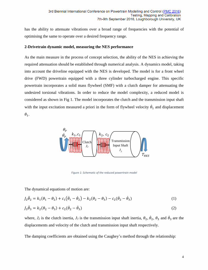
considered as shown in Fig 1. The model incorporates the clutch and the transmission input shaft
with the input excitation measured a priori in the form of flywheel velocity �̇�1 and displacement
𝜃1.
Figure 1: Schematic of the reduced powertrain model
The dynamical equations of motion are:
𝐽2�̈�2 = 𝑘1(𝜃1 − 𝜃2) + 𝑐1(�̇�1 − �̇�2) − 𝑘2(𝜃2 − 𝜃3) − 𝑐2(�̇�2 − �̇�3) (1)
𝐽3�̈�3 = 𝑘2(𝜃2 − 𝜃3) + 𝑐2(�̇�2 − �̇�3) (2)
where, J2 is the clutch inertia, J3 is the transmission input shaft inertia, 𝜃2, �̇�2, 𝜃3 and �̇�3 are the
displacements and velocity of the clutch and transmission input shaft respectively.
The damping coefficients are obtained using the Caughey’s method through the relationship:
Clutch
J2
Transmission
Input Shaft J
3
𝑇𝑅𝐸𝑆
𝑘1, 𝑐1 𝑘2, 𝑐2
5
𝑪 = 𝑱 × 𝑽 × 𝒁 × 𝑽𝑻 × 𝑱 (3)
where, J is the inertia matrix, V is the mass normalised modal matrix and Z is the diagonal
matrix comprising the damping ratios.
As the reduced model does not include other drivetrain components, their effect is included using
the resistance torque TRES , which is a function of aerodynamic drag torque TA and tire rolling
resistance torque TR as:
𝑇𝐴 = 1
2𝜌𝑆𝐶𝑑𝑉2𝑟𝑤 (4)
𝑇𝑅 = (𝑓0 + 𝑓2𝑉2)𝐹𝑧𝑟𝑤 (5)
where, 𝜌 is the air density, 𝑆 is the vehicle frontal area, 𝑉 is vehicle longitudinal velocity, 𝐶𝑑 is
the aerodynamic drag coefficient, 𝑟𝑤 is the tyre rolling radius and 𝐹𝑍 is the vertical tyre load.
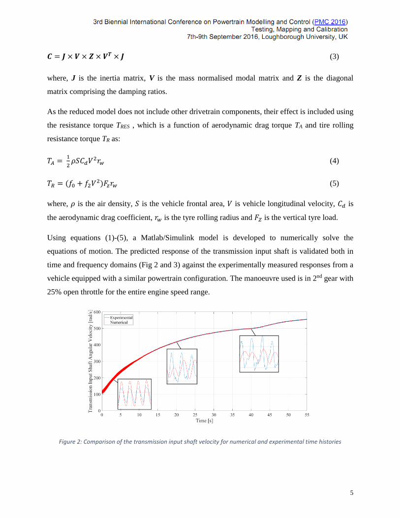
Using equations (1)-(5), a Matlab/Simulink model is developed to numerically solve the
equations of motion. The predicted response of the transmission input shaft is validated both in
time and frequency domains (Fig 2 and 3) against the experimentally measured responses from a
vehicle equipped with a similar powertrain configuration. The manoeuvre used is in 2nd gear with
25% open throttle for the entire engine speed range.
Figure 2: Comparison of the transmission input shaft velocity for numerical and experimental time histories
6
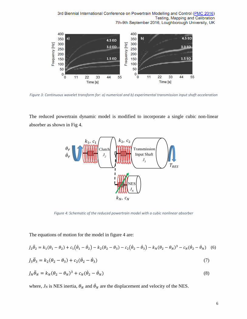
Figure 3: Continuous wavelet transform for: a) numerical and b) experimental transmission input shaft acceleration
The reduced powertrain dynamic model is modified to incorporate a single cubic non-linear
absorber as shown in Fig 4.
Figure 4: Schematic of the reduced powertrain model with a cubic nonlinear absorber
The equations of motion for the model in figure 4 are:
𝐽2�̈�2 = 𝑘1(𝜃1 − 𝜃2) + 𝑐1(�̇�1 − �̇�2) − 𝑘2(𝜃2 − 𝜃3) − 𝑐2(�̇�2 − �̇�3) − 𝑘𝑁(𝜃2 − 𝜃𝑁)3 − 𝑐𝑁(�̇�2 − �̇�𝑁) (6)
𝐽3�̈�3 = 𝑘2(𝜃2 − 𝜃3) + 𝑐2(�̇�2 − �̇�3) (7)
𝐽𝑁�̈�𝑁 = 𝑘𝑁(𝜃2 − 𝜃𝑁)3 + 𝑐𝑁(�̇�2 − �̇�𝑁) (8)
where, JN is NES inertia, 𝜃𝑁 and �̇�𝑁 are the displacement and velocity of the NES.
Clutch J
2
Transmission
Input Shaft J
3
𝜃𝐹
�̇�𝐹
𝑇𝑅𝐸𝑆
NES J
N
𝑘1, 𝑐1 𝑘2, 𝑐2
𝑘𝑁 , 𝑐𝑁

7
The performance of the non-linear energy sink (NES) is validated by comparing the 1.5 Engine
Order (EO) acceleration amplitudes of the transmission input shaft for the system with locked
and active NES. The former is essentially where the NES inertia is added to the clutch inertia,
with latter being the system where the NES engages actively with the primary system. The
reason for choosing 1.5 EO is because this is fundamental engine order of a three-cylinder
engine. Parametric studies are performed to identify the parameters which yield vibration
attenuation over a broad range of response frequencies. These are found to be: JN = 8% of
transmission input shaft inertia, kN = 1.2 x 10⁶ Nm/rad3 and cN = 0.001 Nms/rad. The
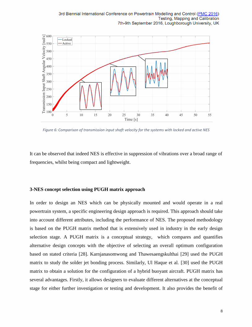
corresponding 1.5 EO transmission input shaft acceleration amplitudes are shown in Fig 5.
Similarly, the effect can also be observed in the fluctuations of the transmission input shaft
velocity as shown in Fig 6.
Figure 5: 1.5 EO acceleration amplitudes of transmission input shaft with locked and active NES (JN = 8% transmission input shaft inertia, kN = 5 x 10⁵ Nm/rad3, cN = 0.001 Nms/rad)
8
Figure 6: Comparison of transmission input shaft velocity for the systems with locked and active NES
It can be observed that indeed NES is effective in suppression of vibrations over a broad range of
frequencies, whilst being compact and lightweight.
3-NES concept selection using PUGH matrix approach
In order to design an NES which can be physically mounted and would operate in a real
powertrain system, a specific engineering design approach is required. This approach should take
into account different attributes, including the performance of NES. The proposed methodology
is based on the PUGH matrix method that is extensively used in industry in the early design
selection stage. A PUGH matrix is a conceptual strategy, which compares and quantifies
alternative design concepts with the objective of selecting an overall optimum configuration
based on stated criteria [28]. Karnjanasomwong and Thawesaengskulthai [29] used the PUGH
matrix to study the solder jet bonding process. Similarly, Ul Haque et al. [30] used the PUGH
matrix to obtain a solution for the configuration of a hybrid buoyant aircraft. PUGH matrix has
several advantages. Firstly, it allows designers to evaluate different alternatives at the conceptual
stage for either further investigation or testing and development. It also provides the benefit of
9
obtaining alternative designs in case the chosen design has some problems. Furthermore, it has
both time and cost saving advantages for companies because if an unfeasible product is
implemented it would have some negative repercussions. Moreover, it not only allows for a
broader concept selection, but also enables critical examination by different functional teams of
each individual criterion which should be satisfied. The chosen route would then have approval
of a broad section of engineers even if their own idea was not selected.
The general process for constructing a PUGH matrix is:
1. Identify and clearly define the design criteria for concept selection.
2. Highlight alternative designs with potential to meet the NES requirement.
3. Rank each individual concept by giving assigning “+” or “-” potential outcome.
4. After scoring each concept, the total score can be determined by summing the number of
+’s and –’s.
It is often encountered that the PUGH matrix is not capable of identifying a better design, but it
certainly helps in narrowing down the options based on the concepts which best satisfy the stated
criteria. If necessary weighting factors for different criteria can be introduced, if the first filter
(iteration) does not lead to a clear decision.
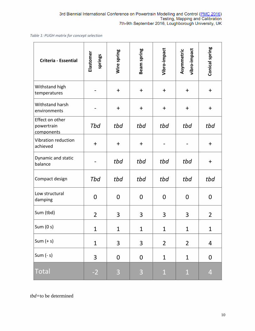
For building the PUGH matrix the six alternative NES concepts were considered, see table 1.
The seven highlighted selection criteria were evaluated for each of the six concepts and “+” or “-
” scores allocated in the matrix cells in accordance. As it can be seen, for a specific criterion,
some concepts performed better than the others. In general this difference is due to the type of
material used to generate the desired non-linear characteristics. In the last rows of the PUGH
matrix the total score through summation “+”, “-“ or “0” scores are stated. This highlights that
the concept 6 is the most appropriate. If the alternative concepts yield similar overall ratings,
then additional design or envisaged operational criteria can be included in the matrix.
10
Table 1: PUGH matrix for concept selection
Criteria - Essential
Elas
tom
er
spri
ngs
Wir
e sp
rin
g
Bea
m s
pri
ng
Vib
ro-i
mp
act
Asy
mm
etri
c
vib
ro-i
mp
act
Co
nic
al s
pri
ng
Withstand high temperatures - + + + + +
Withstand harsh environments - + + + + +
Effect on other powertrain components
Tbd tbd tbd tbd tbd tbd
Vibration reduction achieved + + + - - +
Dynamic and static balance - tbd tbd tbd tbd +
Compact design Tbd tbd tbd tbd tbd tbd
Low structural damping 0 0 0 0 0 0
Sum (tbd) 2 3 3 3 3 2
Sum (0 s) 1 1 1 1 1 1
Sum (+ s) 1 3 3 2 2 4
Sum (- s) 3 0 0 1 1 0
Total -2 3 3 1 1 4
tbd=to be determined
11
4-Concluding Remarks
The paper presents the PUGH matrix as a feasible approach to determine the most appropriate
and physically implementable design concepts for non-linear torsional absorbers for powertrain
applications. The non-linear absorber is used with the objective of suppressing torsional
vibrations over a broad range of frequencies. The PUGH matrix approach facilitates the design in
the conceptual stage by including several criteria and design concepts. This was found to be a
useful process as the NES has not been hitherto been used in vehicular powertrain applications.
This also provided the opportunity to evaluate different designs from other applications and
judge these against new ideas. The design concepts are evaluated for each criterion and finally
ranked. For the proposed NES design, the PUGH matrix highlighted a concept with the most
number of positives, but the others in line were not considered as totally inappropriate.
Acknowledgements
The authors wish to express their gratitude to the Engineering and Physical Sciences Research
Council (EPSRC) for the financial support extended to the “Targeted energy transfer in
powertrains to reduce vibration-induced energy losses” Grant (EP/L019426/1), under which
this research was carried out. Thanks are also due to the industrial partners of the research; Ford
Motor Company, Raicam Clutch and Getrag Ford Transmissions.
References:
[1] Rahnejat, H. (editor), Tribology and Dynamics of Engine and Powertrain. Woodhead
Publishing, Cambridge, 2010.
[2]- Rahnejat, H., Multi-body Dynamics: vehicles, machines and mechanisms, Professional
Engineering Publishing,Bury St.Edmunds, UK, 1998
[3] Swank, M. and Lindemann, P., “Dynamic Absorbers for Modern Powertrains,” SAE Tech.
Pap. 2011-01-1554, 2011.
[4]- Kushwaha, M., Gupta, S., Kelly, P. and Rahnejat, H., "Elasto-multi-body dynamics of a
multicylinder internal combustion engine", Proc. IMechE, Part K: J. Multi-body Dynamics,
2002, 216(4), pp. 281-93.
12
[5]- Kelly, P. and Rahnejat, H.,“Clutch pedal dynamic noise and vibration investigation,” Multi-
body Dyn. Monit. Simul. Tech. Mech. Eng. Publ., 1997.
[6]- Kelly, P., Rahnejat, H., Biermann, J.W. and Hagerodt, B., "Combining design of
experiments and modelling techniques to resolve complex clutch pedal noise and vibration
problems", In IMECHE conference transactions 1998, pp. 297-309.
[7]- Kelly, P., Rahnejat, H. and Biermann J.W., "C553/013/98: Multi-body dynamics
investigation of clutch pedal in-cycle vibration (whoop)", In IMECHE CONFERENCE
TRANSACTIONS 1998, Vol. 13, pp. 167-178
[8]- Singh, R., Xie, H. and Comparin, R.J., "Analysis of automotive neutral gear rattle", J. Sound
and Vibration, 1989, 131(2), pp.177-196.
[9]- Theodossiades, S., Tangasawi, O. and Rahnejat, H., "Gear teeth impacts in hydrodynamic
conjunctions promoting idle gear rattle", J. Sound and Vibration, 2007, 303(3), pp. 632-658.
[10]- Wang, M.Y., Manoj, R. and Zhao, W., "Gear rattle modelling and analysis for automotive
manual transmissions", Proc. IMechE, Part D: J. Automobile Engineering, 2001, 215(2), pp.
241-258.
[11]- Tangasawi, O., Theodossiades, S. and Rahnejat, H., "Lightly loaded lubricated impacts:
Idle gear rattle", J. Sound and Vibration, 2007, 308(3), pp. 418-430.
[12]- De la Cruz, M., Theodossiades, S. and Rahnejat, H., "An investigation of manual
transmission drive rattle", Proc. IMechE, Part K: J. Multi-body Dynamics, 2010, 224(2), pp.167-
181.
[13]- De la Cruz, M., Chong, W.W., Teodorescu, M., Theodossiades, S. and Rahnejat, H.,
"Transient mixed thermo-elastohydrodynamic lubrication in multi-speed transmissions",
Tribology Int., 2012, 49, pp.17-29.
[14]- De la Cruz, M., Theodossiades, S., King, P. and Rahnejat, H., "Transmission drive rattle
with thermo-elastohydrodynamic impacts: numerical and experimental investigations", Int. J.
Powertrains, 2011, 1(2), pp.137-161.
[15]- H. Jianjun, Q. Datong, Z. Yusheng, and L. Yonggang, “Study on natural torsional vibration
characteristics of dual mass flywheel-radial spring type torsional vibration damper,” SAE
Tech. Pap. 2009-01-2062, pp. 1–7, 2009.
13
[16] P. Kelly, B. Pennec, R. Seebacher, B. Tlatlik, and M. Mueller, “Dual mass flywheel as a
means of attenuating rattle,” in Tribology and Dynamics of Engine and Powertrain:
Fundamentals, Applications and Future Trends, 2010, pp. 857–877.
[17]- Theodossiades, S., Gnanakumarr, M., Rahnejat, H. and Kelly, P., "Effect of a dual-mass
flywheel on the impact-induced noise in vehicular powertrain systems", Proc.IMechE, Part D: J.
Automobile Engineering, 2006, 220(6), pp.747-761.
[18]- Menday, M.T., Rahnejat, H. and Ebrahimi, M., "Clonk: an onomatopoeic response in
torsional impact of automotive drivelines", Proc. IMechE, Part D: J. Automobile Engineering,
1999, 213(4), pp. 349-357.
[19]- Theodossiades, S., Gnanakumarr, M., Rahnejat, H. and Kelly, P., "Effect of a dual-mass
flywheel on the impact-induced noise in vehicular powertrain systems", Proc. IMechE, Part D:
J. Automobile Engineering. 2006, 220(6), 747-761.
[20]- Vakakis, A., Gendelman, O.V., Bergman, L. A., McFarland, D. M., Kerschen, G. and Lee,
Y. S., Nonlinear Targeted Energy Transfer in Mechanical and Structural Systems: Solid
Mechanics and its Applications, 1st ed., Springer, 2008.
[21]- Gendelman, O., Manevitch, L. I., Vakakis, A. F.and M’Closkey, R.,“Energy Pumping in
Nonlinear Mechanical Oscillators: Part I—Dynamics of the Underlying Hamiltonian
Systems”, Trans. ASME, J. Appl. Mech., 2001, 68, p. 34.
[22] Vakakis, A. F. and Gendelman, O., “Energy Pumping in Nonlinear Mechanical
Oscillators: Part II—Resonance Capture”, Trans. ASME, J. Appl. Mech., 2001, 68, pp.
42–48.
[23] Kerschen, G., Lee, Y. S., Vakakis, Y. S., McFarland, D. M. and Bergman, L. A.,
“Irreversible Passive Energy Transfer in Coupled Oscillators with Essential Nonlinearity”,
SIAM J. Appl. Math., 2005, 66(2), pp. 648–679.
[24] Sapsis, T. P., Dane Quinn, D., Vakakis, A. F. and Bergman, L. A., “Effective Stiffening
and Damping Enhancement of Structures With Strongly Nonlinear Local Attachments”,
Trans. ASME, J. Vib. Acoust., 2012, 134(1), p. 011016.
[25] McFarland, D. M., Kerschen, G., Kowtko, J. J., Lee, Y. S., Bergman, L. A. and Vakakis,
A. F., “Experimental investigation of targeted energy transfers in strongly and nonlinearly
14
coupled oscillators” , J. Acoust. Soc. Am., 2005, 118(2), pp. 791–799.
[26]- Haris, A., Motato, E., Theodossiades, S., Vakakis, A.F., Bergman, L.A., McFarland, D. M.
and Struve, B., “Targeted Energy Transfer in Automotive Powertrains”, in Dynamics
Systems: Mathematical and Numerical Approaches, 2015, pp. 245–254.
[27] Saava, K., Haris, A., Motato, E., Mohammadpour, M., Theodossiades, S., Rahnejat, H.,
Kelly, P., Vakakis, L. Bergman and McFarland, D., “Damping Effects Introduced by a
Nonlinear Vibration Absorber in Automotive Drivelines at Idle Engine Speeds”, SAE
Tech. Pap. 2016-01-1765, pp. 1–7, 2016.
[28]- Burge, S., “The systems Engineering Tool Box - PUGH Matrix,” 2009.
[29]- Karnjanasomwong, J. and Thawesaengskulthai, N., “TRIZ-PUGH Model , New Approach
for Creative Problem Solving and Decision Making”, in Proc. IEEE IEEM, 2015, pp.
1757–1761.
[30]- Ul Haque, A., Asrar, W., Sulaeman, E., Omar, A. and Ali, JSM., “Pugh Analysis for
Configuration Selection of a Hybrid Buoyant Aircraft”, SAE Tech. Pap. 2015-01-2446,
2015.

15