analysis of an lwr sump cooling concept - kit congress, special seminar on “advances in industrial...
TRANSCRIPT
IAHR Congress, Special Seminar on“Advances in Industrial Hydraulics and Applications to Energy Production”
Beijing, China, September 17-21, 2001
- 1 -
Analysis of an LWR Sump Cooling Concept
G. Grötzbach, L.N. Carteciano, B. Dorr, X. JinForschungszentrum Karlsruhe GmbH
Institut für ReaktorsicherheitD-76021 Karlsruhe, Germany
Abstract
In safety investigations of the European Pressurized water Reactor EPR situations are considered inwhich the core is molten and collects on the core catcher in the sump of the containment. An op-tional cooling concept was investigated at the Research Center Karlsruhe to remove the decay heatutilizing single phase natural convection in the water above the core melt. The natural convectionwas investigated by the SUCOS-2D and -3D scaled experiments. Here, results are reported of nu-merical investigations and interpretations of one of the SUCOS-3D experiments using the computercode FLUTAN. An unexpected temperature distribution is observed in this 3d experiment. Based onthe experimental data it can be presumed that one of the horizontal coolers was slightly tiltedagainst the main flow direction. Approximate numerical investigations show that a tilting of onlyone percent would explain the experimental flow field. In contrast, tilting the horizontal coolerslightly in the circulation direction improves the cooling concept; this could be accurately shown bythe new code version which was recently extended from using a finite volume scheme in Cartesianand cylindrical coordinate systems to a new method based on body fitted grids and a coordinatetransformation.
1. Introduction
The core catcher in the reactor sump is the final safety barrier after a core melt-down accident. Thespreading of the melt and its cooling is investigated in detail world wide, see e.g. in Alsmeyer(2000). In common concepts one is aiming at distributing the heat generating core melt on a largehorizontal surface, called core catcher, and cooling it from below. In the development of the Euro-pean Pressurized water Reactor EPR one aims at achieving a new, improved quality of safety (Bon-homme & Krugmann 1993, Kuczera et al. 1994). Thus, also new concepts for long-term cooling ofthe core melt in the reactor sump are considered, like freezing, fragmenting and cooling it by lead-ing water through the core melt (Alsmeyer & Tromm 1999) or by covering it with water and coolingit from above (Weisshäupl & Bittermann 1995). The latter optional cooling concept utilizes passivesafety features to remove the decay heat from the sump. After the accident, a dry distribution andstabilization of the core melt in the sump region of the reactor is foreseen (Fig. 1). Then cooling ofthe core melt begins with the water from the in-containment refueling water storage tank. Watercooled heat exchangers and condensers in the reactor sump region remove the heat from inside thecontainment. The heat is transferred from the core melt to the cooling devices during the first daysafter the accident by evaporation, and later on by single-phase natural convection and conduction.
The single phase natural convection was experimentally and numerically investigated in the Re-search Center Karlsruhe. The aim of the experimental SUCOS (SUmp COoling Small) program(Knebel & Müller 1995) was to obtain quantitative results which can be transferred to the prototypiccondition in order to make a statement on the feasibility of the single phase sump cooling concept.Two scaled facilities (1:20) were applied in the program: SUCOS-2D (Fig. 2), which represents a

- 2 -
two dimensional plane slab (580*275*235 mm) of a simplified reactor sump geometry, andSUCOS-3D (Fig. 3), which is a three dimensional scaled geometry (580*275*1298 mm) of thesump. Water is heated by a copper plate at the bottom of the pool simulating the core melt andcooled by horizontal and vertical heat exchangers in areas where they are protected against vaporexplosion consequences.
Figure 1. Schematics of the investigated sump cooling concept.
This sump cooling concept was numerically investigated by using the FLUTAN code (Willerding &Baumann 1996). This thermal- and fluid-dynamical computer code is developed in the ResearchCenter Karlsruhe for the numerical analysis of the passive decay heat removal in new reactor sys-tems. It was already extensively validated and applied to analyses of model experiments for the de-cay heat removal in the fast breeder reactor SNR-300 (Weinberg et al. 1996). It is used here to in-vestigate and interpret numerically the single-phase natural convection in the experiments SUCOS-2D and 3D. The aim of this numerical investigation is to consider the feasibility of the sump coolingconcept and to analyze in more detail the experiments.
The first step of the numerical investigation consisted of the simulation and interpretation of aSUCOS-2D experiment (Carteciano et al. 1999). The most important result was that SUCOS-2Dcannot be well reproduced by two-dimensional calculations whereas three-dimensional calculationsreproduce the experiment quite well. The simulations showed that three-dimensional experimentspecific phenomena are significant in the experiments, but these 3d phenomena will be of much lessrelevance in the reactor sump. Furthermore, the analysis of calculations of a SUCOS-2D experimentgave information on the requirements for the numerical modeling of the geometry and boundaryconditions for one of the SUCOS-3D experiments which was the second and final step of the nu-merical investigation of the single-phase sump cooling concept. This step of analyzing in detail theSUCOS-3D experiment is documented in (Carteciano et al. 2000).
The problems of deducing data for the reactor sump from the results of the model experiments arediscussed in (Grötzbach et al. 2000). Transferring the data by scaling laws or CFD-tools is not free

- 3 -
of serious problems because the model experiments showed laminar flows, whereas the reactorsump will have turbulent flow conditions (Knebel & Müller 1997). So, reliable turbulence modelsare required, but purely buoyant flows are still a challenge for any turbulence model, see e.g. Han-jalic (1994, 1999). Also the TMBF, which is explicitly developed for buoyant flows, has up to nowonly been validated for two-dimensional forced, mixed, and natural convection (Carteciano et al.1997, 1999b). Thus, the only way which is nowadays often considered to give a better solution for3d time-dependent flows is to apply Large Eddy Simulation methods (LES). Indeed, there exist al-ready several applications of LES to reactor typical flows (Grötzbach & Wörner 1999).
Chimney
Heat ExchangersConnecting Tubes
Blocking Screws
HeatedCopper Plate
Glass Walls
PVCTeflon
Z
X
Pool (Sump)
Y
X
Heat Exchangers
Sump
Heated Copper Plate
Heat Exchangers
Fig 2. Schematics of the SUCOS-2D test ge-ometry and coordinate system
Fig 3 Schematics of the SUCOS-3D test ge-ometry
The objective of this paper is to discuss the most important results of the numerical interpretation ofthe SUCOS-3D experiment and to conclude on a simple concept improvement. A small geometricdistortion which had to be postulated to exist in the experiment and which reduced the efficiency ofthe cooling concept launched an idea to deduce a minor geometric modification which should in-crease the convective heat removal. Recent simulation results from the new code version applyingnon-orthogonal grids (Jin 2001) help to analyze the effect of tilting the horizontal cooler by a smallamount in the mean flow direction which should improve and stabilize the cooling conditions forthe core melt.
2. FLUTAN Code
FLUTAN is a highly vectorized computer code for 3D fluiddynamic and thermal-hydraulic analysesin Cartesian or cylinder coordinates. It was developed in order to simulate single phase flows withsmall compressibility. The conservation equations for mass, momentum, energy, and turbulencequantities are discretized on a structured grid by using a finite volume method. A staggered grid isused for the velocities. The discretization of the diffusive terms is performed by a central differencemethod (CDS). A first order upwind or one of two second order upwind methods (QUICK (Leonard

- 4 -
1979) and LECUSSO (Günther 1992)) can be chosen for the convective terms. A first order implicitEuler-method is used for time discretization.
Several turbulence models are available in FLUTAN. The most important one for buoyant flows isthe Turbulence Model for Buoyant Flows (TMBF) which consists of a first order k-ε model in alow-Reynolds number formulation and a second order five-equations turbulent heat flux model(Carteciano et al. 1997). In several benchmarks it turned out that the TMBF in its current develop-ment status is a powerful tool at least for forced and mixed convection (Baumann et al. 1997). Spe-cial thermal boundary conditions are available in order to simulate different thermal situations like aheat exchanger model and a wall model. A 3d heat conduction model for the structures was devel-oped for the investigation of the SUCOS experiments. This is necessary for simulating solid struc-tures with internal non-uniform transport of heat; it was required to achieve realistic boundary con-ditions for the fluid domain at the heated copper plate in the SUCOS experiments. The structuretemperatures are discretized on an own grid on which the heat conduction equation is solved in alldimensions independent of the solution of the corresponding equation in the fluid domain.
Recently, a new numerical calculation method was developed (Jin 2001) for more accurate compu-tational fluid dynamics in a complex geometry. The method is basing on body fitted grids. It solvesthe conservation equations in a general non-orthogonal coordinate system which matches curvilin-ear channel walls. In practical applications the non-orthogonal patched grid is generated by a com-mercial grid generator. The resulting geometrical data are transformed by means of an interface pro-gram to the FLUTAN input format.
Figure 4: Arrangement of velocities on the transformed staggered grid used with the new finite vol-ume scheme, simplified to 2d.
The conservation equations are transformed from the Cartesian to a general curvilinear systemkeeping the physical Cartesian velocity components as dependent variables. Using a staggered ar-rangement of variables, the three Cartesian velocity components are defined on every cell surface,Fig. 4. Thus, the coupling between the pressure and the velocities is ensured even on strongly dis-torted grids, and numerical oscillations are avoided. The contravariant velocity for calculating themass flux on a cell surface results from the dependent Cartesian velocity components. The discreti-zation and linear interpolation results in a three dimensional 19-point pressure equation. Treatingthe cross-derivative terms explicitly reduces the system to the usual 7-point equation. The datastructure and solution procedure of this new method is compatible to the one of most codes applyingfinite volume schemes in Cartesian staggered grids; thus it is also fully compatible to the one usedin the Cartesian FLUTAN code version. Therefore, the implementation of the method in FLUTANwas a straightforward activity.
In order to verify the new method, several laminar flows were simulated using orthogonal grids atvarious tilted space directions and in non-orthogonal grids with varying angles between the coordi-

- 5 -
nate axes (Jin 2001). Among the simulated flow types were several duct flows, transient heat con-duction, natural convection in a chimney, and natural convection in cavities. Their results achievevery good agreement with analytical solutions or empirical data. Convergence is also obtained evenfor highly non-orthogonal grids.
3. SUCOS-3D Investigation
3.1 The test facility
The SUCOS-3D test facility consists of a tank of 580*275*1298 mm (Knebel 1999). The outerwalls are 20 mm thick and made of Plexiglas (Fig. 3). The ratio between lengths in the test facilityand in EPR is 1:20. A 30 mm thick copper plate heated from below by electric conductors simulatesthe core melt; it is isolated from the ground, from the walls, and from outside with Teflon. Theheating power is scaled according to the volume of the sump as (1/20)3. Plexiglas structures replacethe structures of concrete in the prototype. The heat exchangers are slab heat exchangers made ofcopper; their cooling tubes have a meander form and use water as a cooling fluid. The horizontalheat exchanger is divided in four separate sections: two small and two large ones. The vertical heatexchangers consist of 8 sections: 4 inner and 4 outer sections respectively. Additional coolers in anupright position are present in the test facility. The space above the heated copper plate is calledpool, see Fig. 2. The space above the horizontal heat exchangers is called horizontal side area. Thespace between the vertical heat exchangers is called vertical side area. The vertical channel withoutheat exchangers connecting the pool and the horizontal side area is called chimney.
Several experiments were performed in SUCOS-3D varying the value of the power input to thecopper plate, the arrangement of the heat exchangers, the inlet temperature of the secondary fluid inthe heat exchangers Tcool, and the level of water. Only temperatures were measured using thermo-couples in two planes near the mid section. The experiments are characterized by a so called pooltemperature. This is the mean temperature in the pool area which is measured by six thermocouplesbelow the tilted roof of the pool.
In order to achieve optimum use of the numerical simulation and interpretation with FLUTAN, aSUCOS-3D experiment had to be chosen which is consistent with the one already simulated forSUCOS-2D. Therefore, one was chosen in which the horizontal and the outer vertical coolers werein operation, while the internal vertical coolers were not active. The electric heat supply of theheated copper plate amounted to 1,240 W. The inlet temperature of the coolant on the secondaryside of the heat exchangers was set to Tcool =20 0C and the flow rate was 20 or 40 g/s. The measuredpool temperature was 32.6 0C.
3.2 Specification of the Computational Model
Only half of the complex but symmetric geometry of the test facility is simulated to reduce the com-putational effort. According to the experience gained from the numerical analysis of SUCOS-2D, allstructures have to be modeled in detail and a very fine grid is necessary for a good resolution of thethin boundary layers near walls and coolers. The mesh size of the grid changes from 8 mm to 1 mm.Ratios of the mesh sizes between two neighboring cells are less than or equal to 2. The 3d grid con-sists of 691,000 fluid cells and 68,000 structure cells. A first order upwind scheme is used to com-pute the convective fluxes of enthalpy and momentum. No turbulence model is used because theflow was laminar in the experiment.
- 6 -
The connecting tubes of the coolers, which are present in the horizontal side area are spatially re-corded and modeled even if it is expected that they would have a minor influence on the naturalconvection than in the calculation of SUCOS-2D. The heat losses to the outside through the lateralwalls are neglected. The active heat exchangers can be modeled by a heat exchanger model or bypre-setting a distribution of the surface temperature or of the surface heat flux. The calculation ofSUCOS-2D showed that it is not necessary to simulate the coolers with the complex heat exchangermodel. It is sufficient to give a distribution for the temperature on the surface between fluid andcooler. The linear distribution of the cooler temperature is approximated by a step function pre-scribing three values for the vertical right coolers. For the horizontal coolers a constant value oftemperature is sufficient because the difference of temperatures between the inlet and outlet coolantwater is less than 1 K. The prescribed values are determined by means of the experimental data.
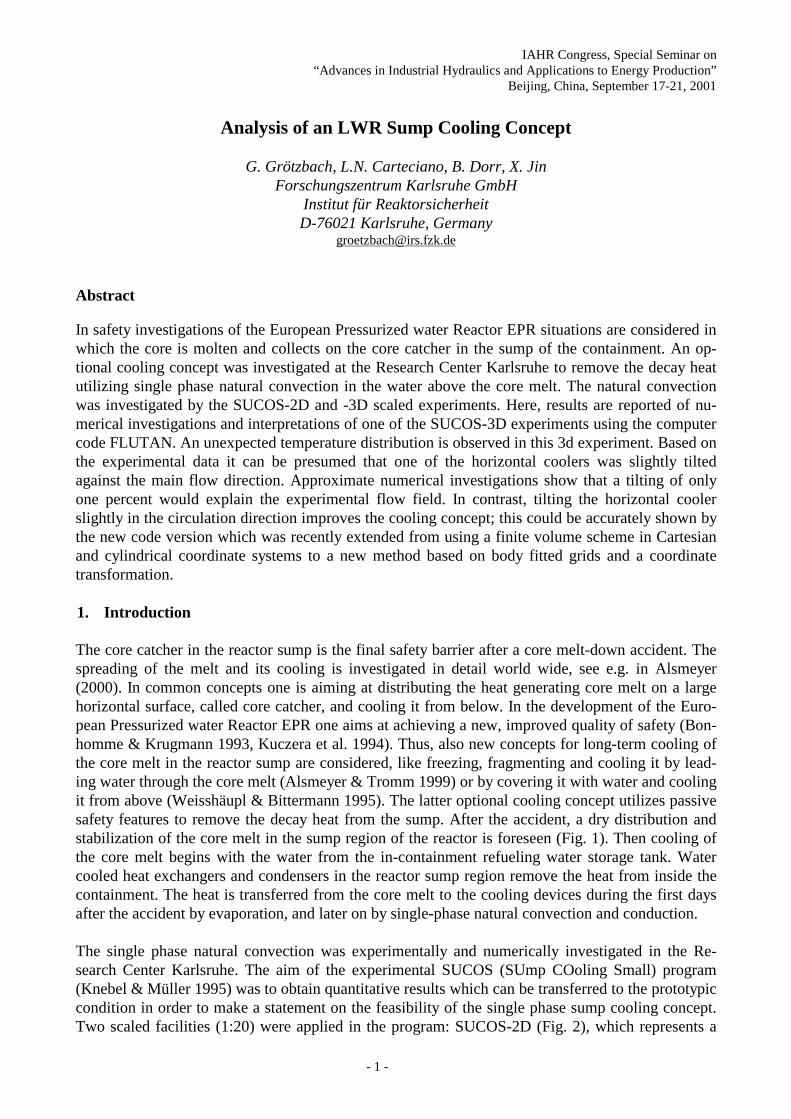
In former simulations for SUCOS-2D it was found that the heated copper plate needs special atten-tion (Kuhn 1996). Even the freely developing circulation sense in the fluid domain is sensitive tothe thermal boundary conditions used at the upper surface of the copper plate (Grötzbach et al.1997). There, the problem of using an artificial Neumann or Dirichlet boundary condition was ana-lyzed by calculating the heat conduction in the copper plate. 2d tests showed the surprising resultthat the copper plate does not ensure a constant heat flux to the fluid, but that it redistributes theheat horizontally in such a strong manner, that the heat flux into the fluid varies along the plate sur-face by more than +/- 50% of its mean value, Fig. 5. Thus, the thermal conduction in the heater plateis also calculated here. A 3d grid is used for the heated plate; the horizontal grid width distributioncorresponds to the one of the fluid region; 5 cells are used in the vertical direction with mesh sizesof 6 mm. The electrical heaters below the copper plate are simulated as a heat flux boundary condi-tion with constant horizontal distribution.
Figure 5: Horizontal distributions of the calculated heat flux Q divided by its mean value Q0 on theupper surface of the copper plate at three different times in SUCOS-2D.
The simulation was performed on a CRAY J916 with a memory need of 2.7 Gbytes. The transientcalculation was preceded by a steady state calculation to obtain an initial flow and temperature fieldfor the transient calculation. The steady state calculation is stopped when an equilibrium in thechanges of temperature and in the balance of the heat fluxes is nearly achieved. This happened after4 h corresponding to 240 h of CPU-time. The transient calculation is performed for a problem timeof 227 s with a time step width of 1.0 s. This corresponds to 407 h CPU-time. The system of thepressure equations is solved by the iterative CRESOR method (Borgwaldt 1990), whereas the sys-tem of the enthalpy equations is solved by the iterative SOR method.
3.3 Results
A feature, which is inherent to most purely buoyant flows, is its local time-dependence. From largeheated plates, the heat is mainly removed by intermittent plume like phenomena. Here, the surfacetemperature on the copper plate, Fig. 6, is very straggly as it is typically found in Rayleigh-Bénard

- 7 -
convection in which the hot plumes rise mainly from the knots of those structures (see the movies inWörner & Grötzbach 1997). In addition, cold plumes are observed which plunge down through thechimney with a low frequency; this phenomenon was not completely filtered out in the experimentby time-averaging of all data over two minutes. This causes the wall heat flux on the copper plate tochange in time, Fig. 5.
Figure 6: Calculated temperature field on the surface of the structures of SUCOS-3D. View frombelow on the fluid domain. The dark areas represent the cooler surface temperatures, the straggly
surface represents the instantaneous temperature distribution on the heated copper plate.
All following FLUTAN results are from the transient calculation and are time averaged over twominutes, like in the experiment (Knebel 1999). The calculated temperature field is shown in Fig. 7.Despite a careful and detailed 3d modeling of the geometrical and thermal characteristics of theSUCOS-3D experiment, the calculated pool temperature Tp,cal=29.2 0C is lower than the measuredone Tp,exp=32.6 0C. The temperature difference appears to be small but the corresponding relativedeviation related to the coolant inlet temperature is with (Tp,cal- Tp,exp) / (Tp,exp- Tcool) = 34% quiteconsiderable. This difference may decide between having single or two-phase flow conditions afterscaling the data up from the model experiment to the reactor sump (Knebel & Müller 1997).
�����
�����
�����
�����
�����
Figure 7: Calculated temperature field in the mid plane of the computational domain.
In order to find reasons for this deviation one should compare the calculated flow field to the ex-perimental one. The calculated flow field for SUCOS-3D is very similar to the experimentally foundand calculated one for SUCOS-2D. A stable natural convection loop develops, Fig. 8: the heatedfluid rises from the copper plate through the chimney to the covered water level; here the warm flowturns right to the horizontal side area and flows on without an intensive contact to the horizontalcooler; the water is mainly cooled in the vertical side area from where it returns to the pool where itis heated again; part of the cold water from the horizontal coolers moves from time to time in form

- 8 -
of cold plumes against the mean flow downwards through the chimney and mixes with the risingheated water. These non-stationary plumes cause the strong time dependence of the heat flux on thecopper plate, Fig 5. According to this flow field, the temperatures in the horizontal side area ofSUCOS-2D are higher than the ones in the pool under the tilted roof, similar to the temperatures inFig. 7.
Figure 8: Velocity vector field in the mid plane of the computational domain. Calculation for
SUCOS-3D.
The flow field in the SUCOS-3D experiment must be reconstructed from the measured temperaturesbecause no velocity measurements were performed. Different to SUCOS-2D here we find in the ex-periment the highest temperatures not in the horizontal side area, but below the tilted roof, Fig. 9.Therefore, a different behavior of the natural convection has to be deduced: we have at least to ex-pect stronger mixing between cold counter-current downward flow with the hot rising fluid in thechimney.
�
=�>P@
7�>��&@
9HUWLFDO 6LGH $UHD
+RUL]RQWDO 6LGH��$UHD
3RRO 6WHS
��������
7LOWHG�URRI
Figure 9: Vertical distributions of measured temperatures in SUCOS-3D (Knebel 1999).
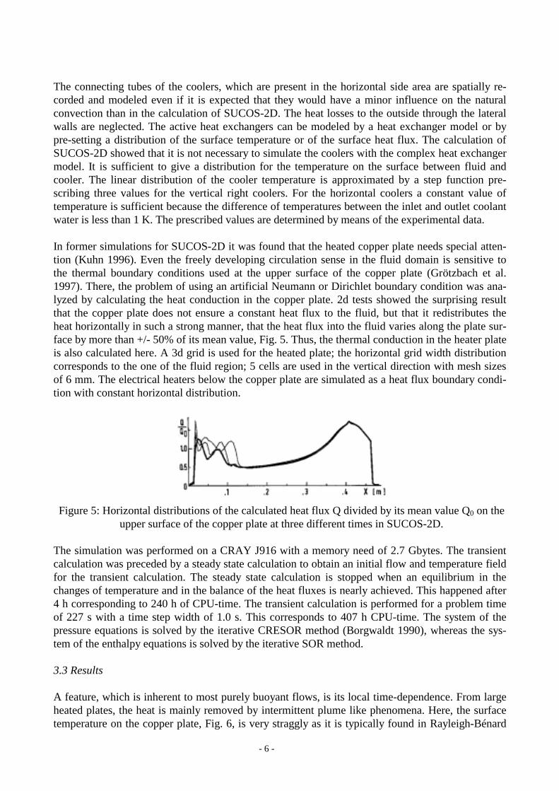
Several reasons for the disagreement in the pool temperature and in the natural convection loopwere investigated. Since SUCOS-2D calculations showed a high sensitivity of the natural convec-tion on small thermal disturbances, the thermocouple support structure installed in the chimney wasadditionally modeled as a thermally interacting structure, but the temperature results in the poolwere only slightly improved. A further numerical study was performed changing the kind of thethermal boundary conditions for the active vertical coolers: values for the wall heat fluxes deducedfrom the experiment were pre-set instead of using surface temperatures. Then, the calculated pooltemperature Tp,cal= 32.8 0C agrees well with the experimental one, Fig. 10: the deviation from the
- 9 -
experiment is reduced from 34% to only 2%. Despite of this positive result, qualitatively the samenatural convection loop is obtained like in the previous calculations. This means, the calculatedflow field still shows no agreement with the reconstructed one for the experiment.
�����
�����
�����
�����
�����
Figure 10: Temperature field in the mid plane of the computational domain. Calculation with tem-perature probe support and pre-set wall heat fluxes for the vertical coolers.
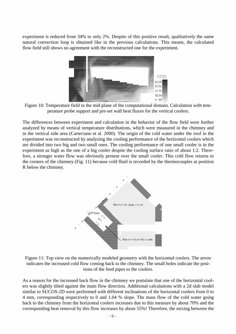
The differences between experiment and calculation in the behavior of the flow field were furtheranalyzed by means of vertical temperature distributions, which were measured in the chimney andin the vertical side area (Carteciano et al. 2000). The origin of the cold water under the roof in theexperiment was reconstructed by analyzing the cooling performance of the horizontal coolers whichare divided into two big and two small ones. The cooling performance of one small cooler is in theexperiment as high as the one of a big cooler despite the cooling surface ratio of about 1:2. There-fore, a stronger water flow was obviously present over the small cooler. This cold flow returns tothe corners of the chimney (Fig. 11) because cold fluid is recorded by the thermocouples at positionR below the chimney.
;
;
;
/
0
5
+RUL]RQWDO�ODUJH�FRROHU
+RUL]RQWDO�VPDOO�FRROHU
&KLPQH\
Figure 11: Top view on the numerically modeled geometry with the horizontal coolers. The arrowindicates the increased cold flow coming back to the chimney. The small holes indicate the posi-
tions of the feed pipes to the coolers.
As a reason for the increased back flow in the chimney we postulate that one of the horizontal cool-ers was slightly tilted against the main flow direction. Additional calculations with a 2d slab modelsimilar to SUCOS-2D were performed with different inclinations of the horizontal coolers from 0 to4 mm, corresponding respectively to 0 and 1.04 % slope. The mass flow of the cold water goingback to the chimney from the horizontal coolers increases due to this measure by about 70% and thecorresponding heat removal by this flow increases by about 55%! Therefore, the mixing between the

- 10 -
cold water and the heated water rising through the chimney is strongly increased like in the experi-ment. These results show that a very small slope of the horizontal coolers can influence the flow be-havior in a drastic way. This would explain the experimental flow field, but a final verification isnot possible because the experimental facility is already disassembled.
4. Improvement of the cooling concept
Technical solutions for safety related problems should not be as sensitive against any physical orgeometrical parameters as it was detected in the interpretation of this experiment. Here the sensitiv-ity is mainly caused by the lack of stabilizing phenomena which are in natural convection usuallythe friction forces; these are in this sump cooling concept of negligible magnitude. Thus one shouldlook for other measures to stabilize and increase the flow at least along the horizontal coolers.
It was found above that a small inclination of a horizontal cooler strongly increases the backflow inthe chimney. Thus, a positive measure to increase the mass flow in the whole system followsstraight forward: the horizontal cooler is inclined by a certain angle in the flow direction; here about2° are chosen as an example for a small angle, see Fig. 12. The recent calculation is performed forthe simpler SUCOS-2D geometry in the general curvilinear coordinate system (Jin 2001). Themodification in the geometry leads to an increase in the velocities in the boundary layer above thehorizontal cooler and thus also in the vertical side area.
Figure 12: Calculated velocity field in the improved SUCOS-2D concept. Velocitymaximum = 0.0187 m/s.
The detailed analysis of the vertical profiles for the time averaged horizontal velocity shows, thecounter clock-wise back flow into the chimney is reduced in the tilted channel and the clock-wiseflow directly above the tilted horizontal cooler is intensified, Fig. 13. The increase in the velocitiesforms a stronger jet flow over the step; consequently a larger recirculation area is formed below thisjet. In total, the mass flow rate in the chimney grew by about 24%. Thus, indeed an improved cool-ing capability for the core melt is achieved in combination with a channel geometry which is lesssensitive against minor geometric distortions. On the other hand, the maximum temperature in thetest rig is not reduced by that amount which corresponds to the increase in the mass flow rate; it isonly decreased by 3.4%. Some of the main reasons for this unexpected small effect are due to the

- 11 -
decrease of the mixing of hot and cold fluid in the chimney, and due to the increased extension ofthe recirculation zone below the jet over the step, which reduces the cooling rate of the copper platein this area.
a) b) c)Figure 13: Measured and calculated vertical velocity profiles in m/s in the pool and above the
horizontal (0°-HK) and tilted (2°-HK) cooler for SUCOS-2D. The profiles are for a) x=0.22m,b) x=0.33m, c) x=0.47m.
5. Conclusions
The former numerical interpretation of SUCOS-2D experiments with the FLUTAN computer codeshowed that good agreement between experiment and calculation can be achieved when local ther-mal disturbances like the feed water pipes to the coolers are recorded in the simulation. Here, thesingle phase natural convection experiment SUCOS-3D is interpreted. Despite recording all impor-tant phenomena in the simulation, some discrepancies are found by analyzing the experimental re-sults from SUCOS-3D: in these experiments the maximum temperature did not occur far above thehorizontal coolers as in SUCOS-2D, but below the tilted roof, and the heat fluxes over the horizon-tal and vertical coolers were not homogeneously distributed. Comparable pool temperatures couldonly be achieved numerically by using the measured heat fluxes at the coolers instead of tempera-ture boundary conditions, but the calculated flow pattern was still different. One explanation for thisstrange result is supported by the experimental data, which indicate a larger backflow in the chim-ney in the 3d experiment. This can be explained by postulating that one of the horizontal coolerswas slightly tilted against the main flow direction. Additional numerical investigations indeed showthat a slope of only one percent would explain the experimental flow field. From this problem of theexperiment one can learn how to improve this sump cooling concept: foreseeing a small slope of thehorizontal coolers downwards in the expected flow direction stabilizes the flow and increases con-siderably the efficiency of the horizontal coolers. This result was numerically confirmed by applyingthe newly developed discretization method using body-fitted coordinates, staggered grids, and ageneral coordinate transformation. All these numerical results confirm, natural convection in largepools, in which pressure drops are negligible, is very sensitive against small disturbances.

- 12 -
Acknowledgements
This work was financially supported by a contract between German Utilities together with Siemensand Forschungszentrum Karlsruhe. X.J. honors the funding by Siemens-KWU of the work on thedevelopment of the numerical scheme for non-orthogonal body-fitted coordinates.
References
Alsmeyer, H., 2000. Proceedings of the OECD workshop on ex-vessel debris coolability. KarlsruheNovember 15-18, 1999, FZKA 6475.
Alsmeyer, H., Tromm, W., 1999. The COMET concept for the cooling of core melts: Evaluation ofthe experimental studies and use in the EPR. FZKA 6186, EXV-CSC(99)-DO36.
Baumann, W., Carteciano, L., Weinberg, D., 1997. Thermal propagation effects in a vertical tur-bulent flow behind a jet block - A benchmark exercise. Journal of Hydraulics Research, Vol. 35,pp. 843-864
Bonhomme, N., Krugmann, U., 1993. Safety and containment of the European Pressurized Reactor(EPR). 5th Int. Seminar on Containments of Nuclear Reactors, Karlsruhe, Germany.
Borgwaldt, H., 1990. CRESOR, A Robust Vectorized Poisson Solver Implemented in the COMMIX-2(V) Thermal-Hydraulic Code. Paper AC064. Int. Conf. On Supercomputing in Nuclear Appli-cations (SNA 90). Mito City, Japan, March 12-16, pp. 346-351.
Carteciano L.N., Weinberg D., Müller U., 1997. Development and Analysis of a turbulence Modelfor Buoyant Flows. Proc. of the 4th World Conf. on Experimental Heat Transfer, Fluid Mechan-ics and Thermodynamics, Bruxelles, Belgium, June 2-6. Vol. 3, S. 1339-46. Pisa Edition ETS.
Carteciano, L.N., Dorr, B., Grötzbach, G., 1999. Theoretical Interpretation of the Single PhaseSump Cooling Experiment SUCOS with the FLUTAN Code. Proc. 9th Int. Meeting on NuclearThermal-Hydraulics NURETH-9, CD-Rom Log 107.
Carteciano, L. N., Wörner, M., Grötzbach, G., 1999b. Erweiterte Turbulenzmodelle für technischeAnwendungen von FLUTAN auf Naturkonvektion. Jahrestagung Kerntechnik 1999, Karlsruhe,18. - 20.5.1999, INFORUM Bonn, S. 129 - 133
Carteciano, L.N., Dorr, B., Grötzbach, G., 2000. Numerical Investigation of the Single Phase Natu-ral Convection in Sump Cooling Experiments with the FLUTAN Code. The Tenth Int. Conf. OnEmerging Nuclear Energy Systems (ICENES 2000), Petten, The Netherlands, 24.-28. Sept.
Grötzbach, G., Wörner, M., 1999. Direct numerical and large eddy simulations in nuclear applica-tions. Int. J. Heat and Fluid Flow (20), pp. 222 - 240
Grötzbach, G., M. Wörner, T. Ammann, A. Blahak, L. Carteciano, B. Dorr, Y. Kimhi, W. Olbrich,W. Sabisch, Q. Ye, M. Alef, St. Genz, A. Hennemuth, G. Janßen, M. Linder, D. Seldner, 1997.Entwicklung von Thermofluiddynamikprogrammen und ingenieurtechnische Anwendungen,Projekt Nukleare Sicherheitsforschung, Jahresbericht 1996, FZKA 5963, pp. 411 - 427
Grötzbach, G., Carteciano, L.N., Dorr, B., 2000. Numerical Analysis of Experiments modelling LWRSump Cooling by Natural Convection.. International Atomic Energy Agency, Technical Com-mittee Meeting on “Natural Circulation Data and Methods for Innovative Nuclear Power PlantDesign”, Vienna, Austria, July 18-21, TEC-DOC to appear
Günther, C., 1992. Fortgeschrittene Upwind-Differenzen-Verfahren zur numerischen Lösung derKonvektions-Diffusionsgleichung. Habilitation, Universität Karlsruhe, KfK 4697.
Hanjalic, K., 1994. Achievements and limitations in modelling and computation of buoyant turbu-lent flows and heat transfer. 10th Int. Heat Transfer Conf., August 14-18, Brighton, U.K.
Hanjalic, K., 1999. Second-Moment Closures for CFD: Needs and Prospects. Int. J. Comp. FluidDyn. 12, 67-97

- 13 -
Jin, X., 2001. Rechenverfahren zur Diskretisierung von Strömungen in komplexer Geometrie mittelskörperangepasster Gitter. Dissertation, Universität Karlsruhe. FZKA 6596
Knebel, J. U., 1999. Personal communication.Knebel, J. U., Müller, U., 1995. Experimental and Numerical Simulation of Passive Decay Heat
Removal by Sump Cooling After Core Melt Down. Proc. 8th Int. Meeting on Nuclear Thermal-Hydraulics NURETH-8, Vol. 2, pp. 1059-1066.
Knebel, J. U., Müller, U., 1997. Scaling of passive decay heat removal by sump cooling. Jahresta-gung Kerntechnik 97, Aachen, 13.-15. Mai, INFORUM Bonn, S.144-47
Kuczera, B., Eglin, W., Weisshäupl, H.A., 1994. Towards an enhanced quality in pressurized waterreactor safety. Kerntechnik 59, pp. 151 – 155.
Kuhn D., 1996. Numerische und experimentelle Untersuchungen zum Sumpfkühlkonzept. Diplomar-beit, Institut für Angewandte Thermo- und Fluiddynamik (IATF), Forschungszentrum Karlsruhe.
Leonard, B. P., 1979. A Stable and Accurate Convective Modelling Procedure Based on QuadraticUpstream Interpolation. Computer Methods in Applied Mechanics & Engineering, Vol. 19, p.59.
Weinberg, D., Rust, K., Hoffmann, H., 1996. Overview Report of RAMONA-NEPTUN Program onPassive Decay Heat Removal. FZKA 5667.
Weisshäupl, H.A., Bittermann, D., 1995. Large spreading of core melt for melt retention–stabili-za-tion. Nucl. Engng. & Design 157, pp. 447 – 454.
Willerding, G., Baumann, W., 1996. FLUTAN 2.0 input specifications. FZKA 5712.Wörner, M., Grötzbach, G., 1997. DNS database of turbulent natural convection in horizontal fluid
layers. World Wide Web-site http://www.fzk.de/irs/turbit