an analytical method for predicting the ship side …naoce.sjtu.edu.cn/upload/1438149054235172.pdfan...
TRANSCRIPT

Marine Structures 41 (2015) 288e311
Contents lists available at ScienceDirect
Marine Structuresjournal homepage: www.elsevier .com/locate/
marstruc
An analytical method for predicting the ship sidestructure response in raked bow collisions
Bin Sun a, Zhiqiang Hu a, *, Ge Wang b
a State Key Lab of Ocean Engineering, Shanghai Jiao Tong University, Shanghai, Chinab Vessel Performance Product, ABS Corporate APM, Huston, USA
a r t i c l e i n f o
Article history:Received 11 January 2015Received in revised form 18 February 2015Accepted 18 February 2015Available online
Keywords:Ship collisionRaked bowCrashworthinessAnalytical methodNumerical simulation
* Corresponding author.E-mail address: [email protected] (Z. Hu).
http://dx.doi.org/10.1016/j.marstruc.2015.02.0070951-8339/© 2015 Elsevier Ltd. All rights reserved
a b s t r a c t
As an increasing number of ships continue to sail in heavy trafficlanes, the possibility of collision between ships has become pro-gressively higher. Therefore, it is of great importance to rapidly andaccurately analyse the response and consequences of a ship's sidestructure subjected to large impact loads, such as collisions fromsupply vessels or merchant vessels. As the raked bow is a commondesign that has a high possibility of impacting a ship side structure,this study proposes an analytical method based on plastic mech-anism equations for the rapid prediction of the response of a ship'sside structure subjected to raked bow collisions. The new methodincludes deformation mechanisms of the side shell plating and thestiffeners attached. The deformation mechanisms of deck plating,longitudinal girders and transverse frames are also analysed. Theresistance and energy dissipation of the side structure are obtainedfrom individual components and then integrated to assess thecomplete crashworthiness of the side structure of the struck ship.The analytical prediction method is verified by numerical simu-lation. Three typical collision scenarios are defined in the numer-ical simulation using the code LS_DYNA, and the results obtainedby the proposed analytical method and those of the numericalsimulation are compared. The results correspond well, suggestingthat the proposed analytical method can improve ship crashwor-thiness during the design phase.
© 2015 Elsevier Ltd. All rights reserved.
.

B. Sun et al. / Marine Structures 41 (2015) 288e311 289
1. Introduction
As continuous streams of ships sail in the heavy traffic lanes, collisions still inevitably occur,although many efforts, such as advanced navigational tools, have been introduced to enhance thesafety level of sailing ships. The structural responses of ships in collision accidents are of great concernin the maritime industry due to the potential consequences to safety, environment pollution, andeconomic investment losses.
The raked bow is a common design. Many ships, including supply vessels, merchant vessels, oilships, and warships, have a raked stem, even if they are equipped with a bulbous bow below. Most shipcollision studies concentrate on the damage caused by the bulbous bow. For example, Hong et al. [1]proposed a direct design procedure for a FPSO side structure that might be subjected to largeimpact loads caused by a bulbous bow; Haris and Amdahl [2] proposed an analytical model toinvestigate the crashworthiness of a ship's side structure struck by rigid bows of two different shapes.Gao and Hu [3] proposed a simplified analytical method for rapid predicting a FPSO side structure'scrashworthiness towithstand a collision by a rigid bulbous bow. Although the bulbous bow is generallystronger than the raked stem, the response of ship side structure to a raked bow collision should not beneglected. For example, Loïc Buldgen et al. [4,5] proposed a simplified analytical method to analyse theoblique collision between two ships.
In the preliminary design stage, it is of great importance to predict the structural performance of aship's side structure to various potential accident scenarios. Additionally, in the risk evaluation afteraccidents occur, it is essential to assess the consequences related to corresponding scenarios rapidly.For these situations, a rational design procedure and calculation tools with high efficiency are required.According to Hong [6], the current approaches to analyse ship collisions can be generally grouped intothree categories: experimental methods, non-linear finite element methods (NLFEMs), and simplifiedanalytical methods. Among the three methods, full-scale or large-scale collision and grounding ex-periments are seldom executed because they are too expensive and risky; thus, small-scale experi-ments are typically used to verify analytical methods; however, the costs are still high, and theexperimental results are difficult to interpret at real-scale conditions due to the intricate scaling effectsinvolved. Because of the explosive development of computer technology, the model test methods arebeing gradually replaced by NLFEMs, which are considered “numerical experiments”, and can providesignificant details and satisfactory results on the deformation process of structures subjected tocollision accidents as long as the modelling parameters are properly set. Moreover, NLFEMs have theadvantage of low cost and repeatable analyses compared with the experimental method. Therefore,NLFEMs are extensively used. For example, Haris and Amdahl [7] used the software LS_DYNA to pro-duce virtual experimental data for several ship collision scenarios. Yu et al. [8] conducted numericalsimulations to verify a simplified analytical method for shoal grounding. Kitamura [9], Endo et al. [10],and Yamada and Endo [11] analysed a series of buffer-bow designs with numerical simulations. Alsosand Amdahl [12] investigated the failure criterions with respect to fracture by numerical analyses.However, establishing the FE model and calculating different accident scenarios is a lengthy process.
Compared with the above mentioned methods, the simplified analytical method has a comparativeadvantage given its reasonable accuracy, cost savings, time efficiency, and, most notably, its superiorityin providing insight into the governing physical processes. Based on these advantages, researchers havedeveloped theoretical models of nearly all ship structural components involved in ship collision andgrounding.
To analyse the crashworthiness of a struck ship, its side structure is typically divided into three basicelements: the web girders, such as decks, transverse frames and longitudinal girders; the side panels,such as outer and inner shell plating; and the stiffeners that are attached to the shell plating. Once theresistance of each basic element is evaluated, the total response of the entire structure can be obtainedby summing the individual resistances. The crushing resistance of web girders was theoretically andexperimentally studied byWierzbicki and CulbertsoneDriscoll [13], Wang and Ohtsubo [14], Simonsen[15], Zhang [16] and Hong and Amdahl [17]. Gao and Hu [18] summarised and compared these variousapproaches and proposed a new theoretical model. Plate tearing typically occurs after a crushingindentation of the web girder reaches a certain distance. Wierzbicki and Thomas [19], Ohtsubo andWang [20] and Zhang [21] proposed plate tearing models that can be used to calculate the tearing force
B. Sun et al. / Marine Structures 41 (2015) 288e311290
of the web girder. For the side plating, Wang et al. [14,22], Simonsen and Lauridsen [23], Lee at al. [24],Zhang [16], and Haris and Amdahl [2] investigated the deformationmechanisms in detail and proposedvarious analytical formulae to obtain the resistance of the side plating. However, Wang et al. [25] foundthat the response of the side plating is strongly dependent on the shape of the striking bow, which wasconfirmed in this study, and a new analytical model of the side plating subjected to a raked bowcollision was obtained. The stiffeners attached to the plating are typically accounted for by thesmearing thickness approach proposed by Paik and Lee [26], but this method might underestimate therole of the stiffeners during a shoal grounding accident [8]. Considering this possible underestimation,Yu and Hu [27e29] made more predictions on the performance of stiffeners during a shoal groundingscenario; however, the performance of the stiffeners attached to the side plating and deck in a collisionscenario has yet to be studied in depth.
Different design purposes determine different design strategies, which have been categorised bythe NORSOK Standard N-004 [30] into three types:
(a) Strength design, which implies that the struck ship is sufficiently strong to resist the collisionforce with minor deformation, and thus, the striking ship is forced to deform and dissipate themajor part of the collision energy;
(b) Ductility design, which implies that the struck ship undergoes large plastic deformations anddissipates the major part of the collision energy;
(c) Shared energy design, which implies that both the struck and striking ship contribute signifi-cantly to the energy dissipation.
When a raked bow strikes a large tanker side structure, the damage to the tanker is the majorconcern in the accident; thus, the ductility design is acceptable and assumes that the striking rakedbow remains undamaged, whereas the tanker side structure is ductile and will absorb most of thestriking energy. Therefore, the ductility design concept is used in this study to analyse the crashwor-thiness of the struck ship's side structure.
In this study, a simplified analytical method is proposed to predict the crashworthiness of ship sidestructures to withstand collision by a rigid raked bow. Three typical collision scenarios are defined, andthe non-linear finite element software LS_DYNA is used to simulate the collision process to identify thedeformation mechanism of the side structure. Based on the numerical simulation results, a newtheoretical model of the side plate, subject to a raked bow collision, is proposed, and an analyticalmodel of the deformed stiffeners attached to the plate is built. Additionally, an integrated analyticalmethod for predicting the structural response of the entire ship side structure is proposed. Theanalytical method is verifiedwith the numerical simulation to assess the crushing forces, deformations,and energy dissipation. The results of the analytical method and those of the numerical simulationcorrespond well. Therefore, the proposed analytical method can be used in the preliminary designstage to assess the crashworthiness of the ship side structure with the advantages of time saving andreasonable accuracy.
2. Numerical simulations
To investigate the deformation mechanism of the side structural components of the struck ship,numerical simulation can be first applied to simulate detailed collision processes.
2.1. Finite element model
A tanker is chosen as the struck ship, and a supply vessel with a raked bow is selected as the strikingship. The principle dimensions of the tanker and the supply vessel employed in the numerical simu-lation are given in Tables 1 and 2, respectively.
Because a ship collision is a localised event, only a part of one compartment of the tanker thatextends between two transverse bulkheads and contains all of the side structures is modelled. Thefinite element model of the side structure includes major side structural components, such as the side

Table 1Main particulars of the struck tanker.
Item Value
Length 288.0 mBreadth 65.0 mDepth 29.4 mDesign draught 22.0 mLength of one compartment 35.0 mSpacing of double side plantings 3.38 mSpacing between transverse web frames 5.0 mSpacing between longitudinal girders 7.2 m
Table 2Main particulars of the striking supply vessel.
Item Value
Length 107.0 mBreadth 15.0 mDepth 7.49 mDesign draught 6.4 m
B. Sun et al. / Marine Structures 41 (2015) 288e311 291
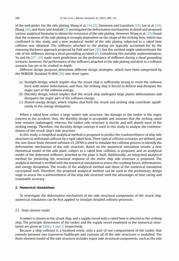
plating, the deck with stiffeners, the longitudinal girders, and the transverse frames. The materialyielding stress and ultimate stress of the deck and its stiffeners are defined as 355 and 600 MPa,respectively, whereas the material yielding stress and ultimate stress of the other side structuralcomponents are set to 235 and 300 MPa, respectively. The critical fracture strain is used to define thefailure of the material. According to the NORSOK Standard N-004 [30], the parameter can be definedas 0.2 and 0.15 for S235 and S355, respectively. The contacts that occur between structural compo-nents during the simulation are treated as automatic single-surface contact in LS_DYNA, and thefriction coefficient value is set at 0.3. The selected element type of the finite element model inLS_DYNA is a four-node quadrilateral Belytschko-Tsay shell element. To obtain a practical simulationtime as well as capture the major deformation modes, the reasonable length of the mesh size is set as200 mm. There are a total of 123,520 elements in the finite element model. The side structure finiteelement model is restrained at both longitudinal ends by fixing the six degrees of freedom. Thus, themotions of the tanker are not considered in the analysis. The detailed structure layout is shown inFig. 1.
The striking ship is a 5000 DWT supply vessel with a raked bow. In the simulation, the structures ofthe striking ship are defined as rigid properties, and the impact velocity is set at 3 m/s. The contactsbetween the striking ship and struck side structure are defined as automatic surface-to-surface contactin LS_DYNA, and the friction coefficient value is set at 0.3. The finite element model of the supply vesselis illustrated in Fig. 2.
2.2. Simulation cases
Because the supply vessel, whose draught is normally shallow, is smaller than the large tanker,whose draught is normally deep, the impact positions in collision accidents are always concentrated onthe upside of the tanker, and the impact indentation is not deep. Thus, the collision process consideredin this study is until contact occurs between the striking ship and inner shell plating, and three typicalcollision scenarios are defined, as illustrated in Fig. 3. The three scenarios are:
(a) Scenario 1: The impact position is located on the deck and between two transverse frames of thetanker. This is a likely position when the tanker in a laden condition;
(b) Scenario 2: The impact position is located between the deck and uppermost longitudinal girderand between the two transverse frames of the tanker. The forecastle deck of the supply vessel isthe first to contact the tanker side; and
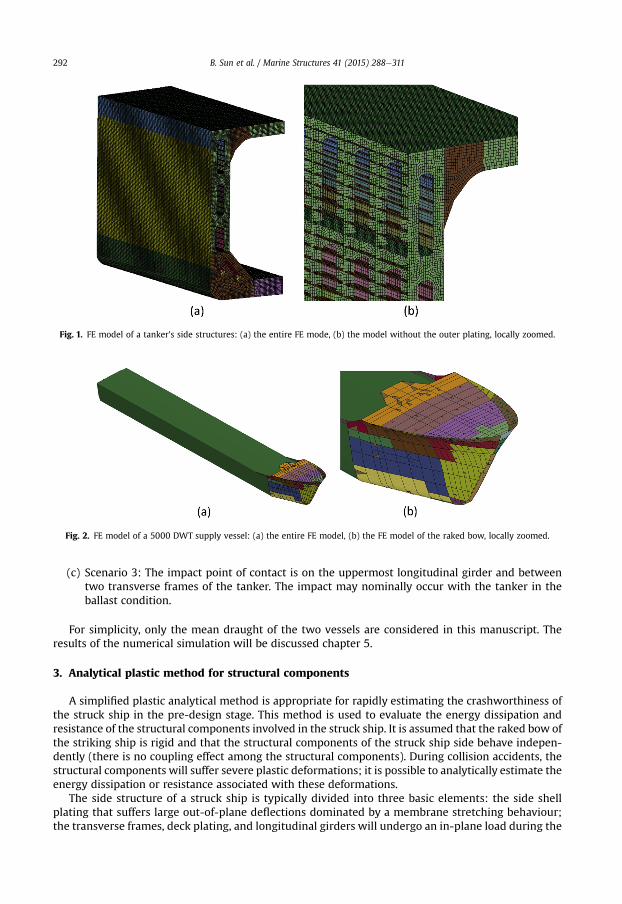
Fig. 1. FE model of a tanker's side structures: (a) the entire FE mode, (b) the model without the outer plating, locally zoomed.
Fig. 2. FE model of a 5000 DWT supply vessel: (a) the entire FE model, (b) the FE model of the raked bow, locally zoomed.
B. Sun et al. / Marine Structures 41 (2015) 288e311292
(c) Scenario 3: The impact point of contact is on the uppermost longitudinal girder and betweentwo transverse frames of the tanker. The impact may nominally occur with the tanker in theballast condition.
For simplicity, only the mean draught of the two vessels are considered in this manuscript. Theresults of the numerical simulation will be discussed chapter 5.
3. Analytical plastic method for structural components
A simplified plastic analytical method is appropriate for rapidly estimating the crashworthiness ofthe struck ship in the pre-design stage. This method is used to evaluate the energy dissipation andresistance of the structural components involved in the struck ship. It is assumed that the raked bow ofthe striking ship is rigid and that the structural components of the struck ship side behave indepen-dently (there is no coupling effect among the structural components). During collision accidents, thestructural components will suffer severe plastic deformations; it is possible to analytically estimate theenergy dissipation or resistance associated with these deformations.
The side structure of a struck ship is typically divided into three basic elements: the side shellplating that suffers large out-of-plane deflections dominated by a membrane stretching behaviour;the transverse frames, deck plating, and longitudinal girders will undergo an in-plane load during the
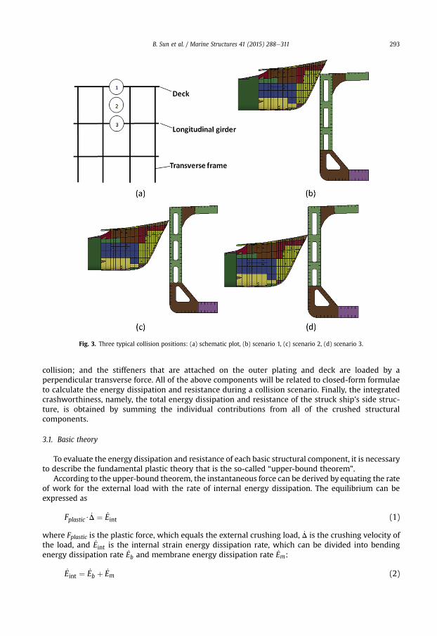
Fig. 3. Three typical collision positions: (a) schematic plot, (b) scenario 1, (c) scenario 2, (d) scenario 3.
B. Sun et al. / Marine Structures 41 (2015) 288e311 293
collision; and the stiffeners that are attached on the outer plating and deck are loaded by aperpendicular transverse force. All of the above components will be related to closed-form formulaeto calculate the energy dissipation and resistance during a collision scenario. Finally, the integratedcrashworthiness, namely, the total energy dissipation and resistance of the struck ship's side struc-ture, is obtained by summing the individual contributions from all of the crushed structuralcomponents.
3.1. Basic theory
To evaluate the energy dissipation and resistance of each basic structural component, it is necessaryto describe the fundamental plastic theory that is the so-called “upper-bound theorem”.
According to the upper-bound theorem, the instantaneous force can be derived by equating the rateof work for the external load with the rate of internal energy dissipation. The equilibrium can beexpressed as
Fplastic$ _D ¼ _Eint (1)
where Fplastic is the plastic force, which equals the external crushing load, _D is the crushing velocity ofthe load, and _Eint is the internal strain energy dissipation rate, which can be divided into bendingenergy dissipation rate _Eb and membrane energy dissipation rate _Em:
_Eint ¼ _Eb þ _Em (2)

B. Sun et al. / Marine Structures 41 (2015) 288e311294
It is assumed that the two energy dissipation patterns are uncoupled and that the bending energydissipation is concentrated on the plastic hinge lines.
The bending energy dissipation rate _Eb and membrane energy dissipation rate _Em can be expressedby the following equations:
_Eb ¼Xni¼1
Mp _bili (3)
_Em ¼ZS
Np _εavgdS (4)
whereMp is the plastic bending moment, _bi and li are the curvature rate and length of hinge number i,respectively, Np is the plastic membrane force, and _εavg is the average tensile strain rate.
The material is assumed to be rigid-perfectly plastic, and the effect of elastic strain is neglected. Aflow stress s0, which is the average value of the yield stress sy and ultimate stress su, is used to considerthe hardening effect.
3.2. Deformation mechanism of the side plating
Several researchers have investigated the deformation mechanism of the side plating, and it isaccepted that the response of the side plating is strongly dependent on the shape of the striking bow. Anew theoretical model of the deformed side plating subject to raked bow impact is proposed here.
3.2.1. Analytical model of the side platingThe deformation pattern of the outer side plating in scenario 1 of the numerical simulations is
shown in Fig. 4. Based on this pattern, a new theoretical deformation model is proposed, as shown inFig. 5.
The deflection of the plate D is expressed as
D ¼ L1 tan a1 ¼ L2 tan a2 ¼ H1 tan q (5)
where L1 and L2 are the length of the left and right sides of the deformed plate, respectively, which aretypically determined by the adjacent transverse frames whose deformations are not severe, a1 and a2are the instantaneous rotation angles of the left and right side in the longitudinal direction, respec-tively, H1 is the height of the deformed plate, which is determined by the adjacent longitudinal girder,and q is the instantaneous rotation angle of the plate in the vertical direction.
Fig. 4. Deformation pattern of the side plating in a numerical simulation: (a) side view; (b) bottom view.

Fig. 5. Deformation model of the side plating.
B. Sun et al. / Marine Structures 41 (2015) 288e311 295
Then, the crushing velocity of the load _D can be expressed as
_D ¼ L1cos2a1
_a1 ¼ L2cos2a2
_a2 ¼ H1
cos2 q_q (6)
where _a1 and _a2 are the angular bending rates of the left and right sides in the longitudinal direction,respectively, and _q is the angular bending rate of the plate in the vertical direction.
During the crushing process, the strain of the deformed plate on the left side ε1 can be formulated as
ε1 ¼�
lcos a1
� l��
l ¼ 1cos a1
� 1 (7)
where l is the length of an arbitrary plate strip.Thus, the strain rate of the plate on the left side _ε1 can be expressed as
_ε1 ¼ sin a1
cos2a1_a1 (8)
Considering the geometry, the strain and strain rate of the plate on the right side can be expressedas
ε2 ¼ 1cos a2
� 1 (9)
_ε2 ¼ sin a2
cos2a2_a2 (10)
Integrating Equations (8) and (10) into Equation (4), the membrane energy dissipation rate can beobtained as
_Em ¼ N0 sideplate
�S1
sin a1
cos2a1_a1 þ S2
sin a2
cos2a2_a2
�(11)
where S1 and S2 are the areas of the left and right sides of the deformed plate, respectively, andN0_sideplate is the fully plastic membrane stretching force per length of the plate trip and is expressed as
N0 sideplate ¼ s0tsideplate (12)
where tsideplate is the thickness of the outer side plating.

B. Sun et al. / Marine Structures 41 (2015) 288e311296
The proportion of the bending energy dissipation is small. Neglecting this component does notintroduce large errors into the predicted total energy absorption. When the membrane energy dissi-pation rate is obtained, the instantaneous resistance of the side plating can be derived by integratingEquations (1), (2), (6) and (11):
Fp ¼_Em_D
¼ N0 sideplateS1 sin a1
L1þ N0 sideplateS2 sin a2
L2¼ 0:5N0 sideplateH1ðsin a1 þ sin a2Þ (13)
When the collision position is located a certain distance under the deck, such as in scenarios 2 and 3,the deformation pattern of the side plating is similar to that of scenario 1. The theoretical model isillustrated in Fig. 6.
Thus, the resistance of the plate is the combination of the upper part and lower parts. The resistanceof each part can be obtained via the analytical method presented above.
After the fracture of the side plating occurs, the crack will spread rapidly in the longitudinal di-rection. In this circumstance, the deformation of the upside part will not continue, and the deformationmechanism of the lower part is the same as that mentioned above; the deformation pattern of the sideplating from the numerical simulation is shown in Fig. 7.
3.2.2. Numerical validation of the proposed methodOnce the analytical method for predicting the resistance of the deformed outer side plate is ob-
tained, the results can be validated by numerical simulations using LS_DYNA. As shown in Fig. 8, goodagreement is obtained between the numerical and analytical results.
3.3. Deformation mechanism of the stiffeners
The role of the stiffeners attached to the plate is to improve structural strength. Researchers usuallytake the function of the stiffeners into account by the approach of smearing thickness, but this methodmay underestimate the role of the stiffeners. Thus, a new theoretical model of the deformed stiffenersubjected to raked bow impact is proposed. In the present study, stiffeners and side plating are treatedseparately to simplify the prediction method. The feasibility of this approach has been reported by LoïcBuldgen et al. [4].
Fig. 6. Deformation model of the side plating.

Fig. 7. Deformation model of the side plating after fracture.
B. Sun et al. / Marine Structures 41 (2015) 288e311 297
3.3.1. Analytical model of the stiffenerThe deformation pattern of a stiffener attached to the side plating in the numerical simulation is
represented in Fig. 9. The proposed analytical model is shown in Fig. 10.As the stiffeners are welded onto the plate, an assumption is made that the stiffeners deform
simultaneously with the plating and maintain a stable deformation process. The ends of the stiffenersare regarded as fixed on the adjacent transverse frames whose deformation is not severe.
The deflection of the stiffener D is expressed as
D ¼ l1 tan q1 ¼ l2 tan q2 (14)
where l1 and l2 are the longitudinal distance from the impact point to the left and right undamagedtransverse frames, respectively, and q1 and q2 are the instantaneous rotation angles of the left and rightrollers, respectively.
Then, the crushing velocity of the load _D can be expressed as
_D ¼ l1cos2q1
_q1 ¼ l2cos2q2
_q2 (15)
where _q1 and _q2 are the angular bending rates of the left and right rollers, respectively.The energy dissipated at the side rollers is mainly through plastic bending and can be obtained by
Equation (3) as
_E1 ¼ M0 stiffenerts�_q1 þ _q2
�(16)
At the middle roller, there are two major internal dissipation patterns, namely, plastic bending andmembrane stretching. The friction resistance affects the energy dissipation through membranestretching. The bending moment capacity is reduced by the presence of the axial force. The energydissipation rate can be obtained by Equations (3) and (4):
_E2 ¼ M1ts _q1 þM2ts _q2 þ N1ts _u1 þ N2ts _u2 (17)
where ts is the thickness of the stiffener, and _u1 and _u2 are the strain rates of the left and right sides ofthe stretched stiffener, respectively, expressed as

Fig. 8. Comparison between the numerical and analytical solutions: (a) scenario 1, (b) scenario 2, (c) scenario 3.
B. Sun et al. / Marine Structures 41 (2015) 288e311298
_u1 ¼ sin q1
cos2q1_q1 (18)
_u2 ¼ sin q22
_q2 (19)
cos q2M and N are the bending moment and normal force in the yield condition, respectively. Theinteraction law between the normal force and bending moment is described by the yield locus pre-sented in Fig. 11 and can be expressed as
MM0 stiffener
þ
NN0 stiffener
!2
¼ 1 (20)

Fig. 9. Deformation pattern of the stiffener in numerical simulations.
Fig. 10. Analytical model of the stiffener.
B. Sun et al. / Marine Structures 41 (2015) 288e311 299
where M0_stiffener and N0_stiffener are the fully plastic bending moment and fully plastic force perthickness of the stiffener respectively, and can be formulated as
M0 stiffener ¼s0H2
s4
(21)
N0 stiffener ¼ s0Hs (22)
where Hs is the height of the stiffener.
Fig. 11. Interaction law between the normal force and bending moment.

B. Sun et al. / Marine Structures 41 (2015) 288e311300
According to the normality criterion
�_q_u
�¼ _l
8>><>>:
vfvMvfvN
9>>=>>; (23)
the expression of normal force N can be obtained as
N ¼N20 stiffener
2M0 stiffener$_u_q
(24)
Then, by integrating Equations (16)e(20) and (24), the total energy dissipation rate of the stiffenercan be obtained as
_Es ¼ _E1 þ _E2 ¼ 2M0 stiffenerts�_q1 þ _q2
�þ N20 stiffener
4M0 stiffenerts
�sin2
q1
cos4q1_q1 þ
sin2q2
cos4q2_q2
�(25)
Finally, the instantaneous resistance of the stiffener can be derived by integrating Equations (1), (15)and (25):
Fs ¼_E_D¼ 2M0 stiffenerts
�cos2q1
l1þ cos2q2
l2
�þ
N20 stiffener
4M0 stiffenerts
�sin2
q1
l1 cos2q1þ sin2
q2
l2 cos2q2
�(26)
It should be emphasized that N is never equal to or larger than N0_stiffener. If N ¼ N0_stiffener, we haveM ¼ 0, and thus, Equation (26) can be replaced by
Fs ¼ M0 stiffenerts
�cos2q1
l1þ cos2q2
l2
�þ N0 stiffenerts
�sin q1
l1þ sin q2
l2
�(27)
When the stiffeners attached on the deck are considered, the deformation mechanism remains thesame, then the resistance can be calculated by replacing the thickness ts by the heightHs of the stiffenerin Equations (26) and (27).
3.3.2. Numerical validation of the proposed methodOnce the analytical method for predicting the resistance of the deformed stiffener was obtained, the
results can be validated by numerical simulations using LS_DYNA. As shown in Fig. 12, good agreementis obtained between the numerical and analytical results.
3.4. Deformation mechanism of the web girder
Many researchers have studied the deformationmechanism of the web girder subjected to in-planeconcentrated or patch loads using both experiments and NLFEMs. A number of analytical methods forassessing the crushing resistance of the web girder have been proposed based on the plastic mecha-nism analysis of theoretical deformation models. Gao and Hu [18] summarised and compared theexisting analytical methods for instantaneous crushing resistance and proposed a more detailedtheoretical deformation model that accounts for some important deformation features of the webgirder based on numerical simulations.
When the crushing indentation reaches a certain distance, the plating tears. The plate tearingprocess can be separated into an initiation phase and steady-state phase. In the initiation phase, thetearing force increases with the crushing indentation. There is a constant resistance in the steady-state
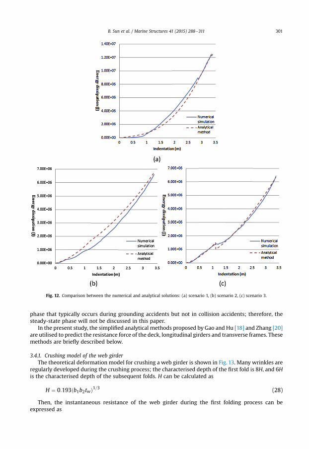
Fig. 12. Comparison between the numerical and analytical solutions: (a) scenario 1, (b) scenario 2, (c) scenario 3.
B. Sun et al. / Marine Structures 41 (2015) 288e311 301
phase that typically occurs during grounding accidents but not in collision accidents; therefore, thesteady-state phase will not be discussed in this paper.
In the present study, the simplified analytical methods proposed by Gao and Hu [18] and Zhang [20]are utilised to predict the resistance force of the deck, longitudinal girders and transverse frames. Thesemethods are briefly described below.
3.4.1. Crushing model of the web girderThe theoretical deformation model for crushing a web girder is shown in Fig. 13. Many wrinkles are
regularly developed during the crushing process; the characterised depth of the first fold is 8H, and 6His the characterised depth of the subsequent folds. H can be calculated as
H ¼ 0:193ðb1b2twÞ1=3 (28)
Then, the instantaneous resistance of the web girder during the first folding process can beexpressed as
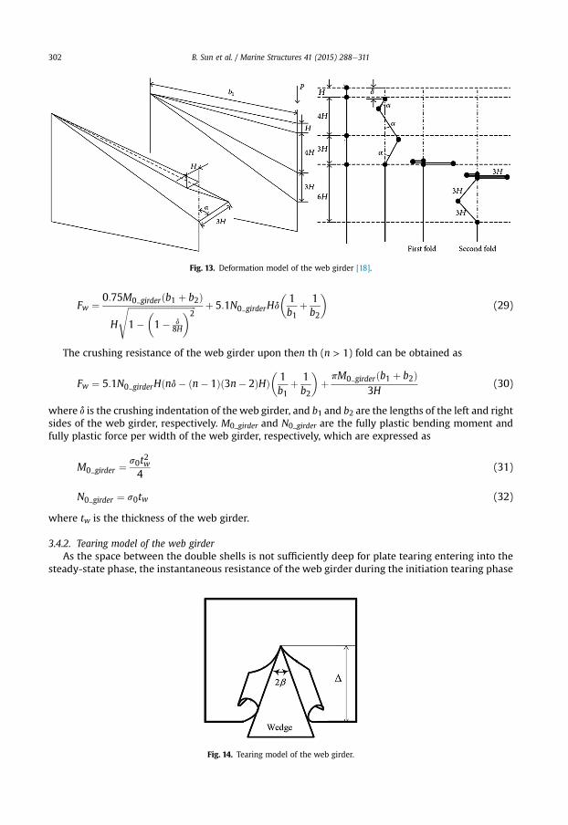
Fig. 13. Deformation model of the web girder [18].
B. Sun et al. / Marine Structures 41 (2015) 288e311302
Fw ¼ 0:75M0 girderðb1 þ b2Þ
H
ffiffiffiffiffiffiffiffiffiffiffiffiffiffiffiffiffiffiffiffiffiffiffiffiffiffiffiffiffiffiffiffi1�
�1� d
8H
�2s þ 5:1N0 girderHd
�1b1
þ 1b2
�(29)
The crushing resistance of the web girder upon then th (n > 1) fold can be obtained as
Fw ¼ 5:1N0 girderHðnd� ðn� 1Þð3n� 2ÞHÞ�1b1
þ 1b2
�þ pM0 girderðb1 þ b2Þ
3H(30)
where d is the crushing indentation of the web girder, and b1 and b2 are the lengths of the left and rightsides of the web girder, respectively. M0_girder and N0_girder are the fully plastic bending moment andfully plastic force per width of the web girder, respectively, which are expressed as
M0 girder ¼s0t2w4
(31)
N0 girder ¼ s0tw (32)
where tw is the thickness of the web girder.
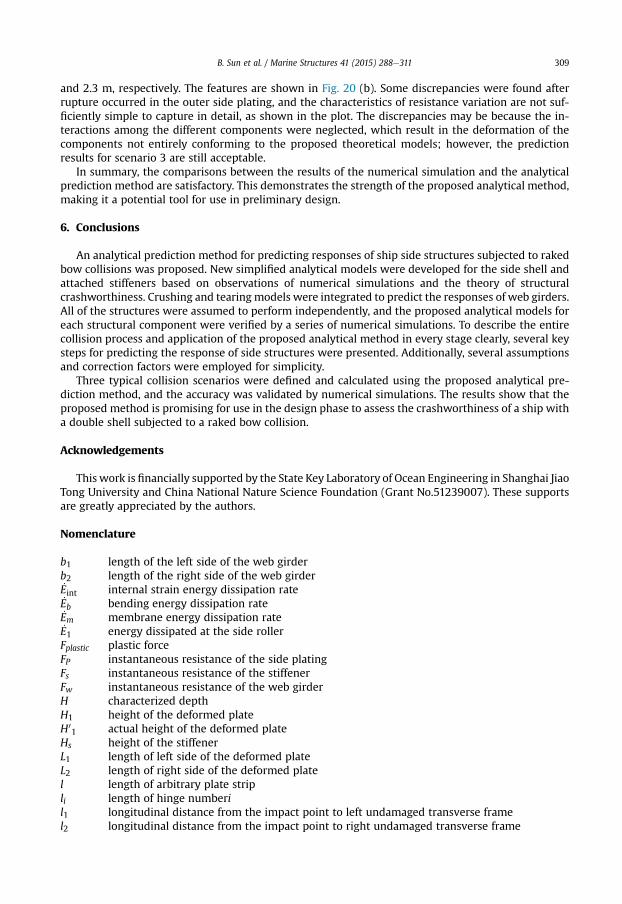
3.4.2. Tearing model of the web girderAs the space between the double shells is not sufficiently deep for plate tearing entering into the
steady-state phase, the instantaneous resistance of the web girder during the initiation tearing phase
Fig. 14. Tearing model of the web girder.

B. Sun et al. / Marine Structures 41 (2015) 288e311 303
is considered; the theoretical model is shown in Fig. 14. The instantaneous resistance can be expressedas
Fw ¼ 1:942s0t1:5w D0:5
ε0:25u ðtan bÞ0:5
�1þ m
tan b
�(33)
where εu is the ultimate strain of the web girder, b is the half apex angle of the indenting wedge, and m
is the friction coefficient.
4. Prediction procedure
There are several key steps to predicting the response of ship side structures to a raked bowcollision; these steps are presented below.
4.1. Definition of the collision scenario
Prior to the analysis of ship collision, it is necessary to define the collision scenario. The head-oncollision is discussed in this paper because it is considered a severe scenario. Then, three impact po-sitions were selected considering the relative size of the ships in a collision accident (see Fig. 3).
4.2. Identification of the damaged structures in the collision process
To reduce the computational complexity, it is assumed that before the raked bow contacts astructural component of the ship's side, the deformation of the component will not occur and thecomponent will not participate in withstanding the impact.
A collision is typically a local event. The failure patterns proposed have clear boundaries thatseparate the deformed region from the undeformed region. The deformation region is assumed tobe determined by the nearest undamaged supporting web girders, which limit the deformation ofthe structures adjacent to them. These assumptions make this analytical prediction methodfeasible.
Once the outlines of the ships involved in the collision accidents are provided and the collisionscenarios are determined, the structural members involved in the collision process can be determinedby the combination of the outlines of the raked bow from the draft of the striking ship and thestructural layout of the side structure from the draft of the struck ship. It is convenient to simulate thecollision process in a plane figure and identify the contact situation of the two ships; then, thestructural components that participate in the resistance calculation during the collision process can beobtained.
One example of the simulations is illustrated in Fig. 15. The outline of the raked bow and thestructural layout of the side structure (without stiffeners) from the top view are combined tosimulate the collision process. The beginning of the collision is shown in Fig. 15(a), where theindentation is 0 m. In Fig. 15(b), the outer plating has been crushed by the bow, but contact betweenthe bow and transverse frames does not occur; thus, the transverse frames act as the boundaries inthis case, and only the outer plating contributes to the resistance of the side structure. In Fig. 15(c),when the indentation is 0.48 m, the transverse frames begin to contact the raked bow, and theybegin to contribute to the total resistance. In Fig. 15(d), the transverse frames have also been crushedby the bow, but they are still limiting the deformation of the outer plating. In Fig. 15(d), point Arepresents the foremost point of the striking bow, points B and C denote the endpoints of thetransverse frames, points D and E denote the intersections of lines AB and AC, the horizontal straightline represents the outer side plating, and points D and E represent the boundaries of the deformedouter side plating.
The longitudinal components involved in the collision can be determined in a similar manner thatcombines the outline of the raked bow and the structural layout of the side structures from the sideview.

Fig. 15. Simulation of the collision process (top view).
B. Sun et al. / Marine Structures 41 (2015) 288e311304
4.3. Prediction of the rupture of the outer plating
Many researchers use the maximum strain failure criterion in a tensile tearing failure model topredict the rupture of the plate subjected to an out-of-plane load. This criterion states that thestructure ruptures when the maximum strain in a structure reaches a critical strain. This criterion wasused in the present analysis.
The tensile ductility of mild steel typically ranges from 0.20 to 0.35. Considering scale effects be-tween test coupons, large-scale structures and initial material defects, Amdahl [31] recommended thatcritical strain values between 0.05 and 0.10 be used for full-scale side collision assessment. In thepreliminary design stage, the critical strain value can be chosen by the designers. The relationshipbetween the indentation and maximum strain of the outer plating can be obtained by substitutingEquation (7) or (9) into Equation (5):
D ¼ L1ffiffiffiffiffiffiffiffiffiffiffiffiffiffiffiffiffiffiffiffiε2m þ 2εm
q¼ L2
ffiffiffiffiffiffiffiffiffiffiffiffiffiffiffiffiffiffiffiffiε2m þ 2εm
q(34)
where εm is the maximum strain of the outer plating chosen by designers and L1 and L2 are the lengthsof the left and right sides of the deformed plate, respectively.
The outer plating typically only ruptures when the impact point is under the deck, such as incollision scenarios 2 and 3.
4.4. Introduction of correction factors for predicting the resistance of the outer plating
In an actual collision process, the deformation of the outer plating always deviates somewhat fromthe ideal conditions proposed previously.
When the impact point is on the intersection of the deck and the outer plating, such as in collisionscenario 1, or after the rupture of the outer plating (scenarios 2 and 3), some differences between thepredicted parameters and actual parameters are detected in numerical simulations, as shown in Fig. 16.The ideal indentation is the crushing distance of the raked bow, which is equal toD, whereas the actualindentation is the real crushing distance of the side plating, which is smaller than the ideal indentationand expressed as D0. Similarly, the actual deformation height of the side plating, which is expressed as

Fig. 16. Deformation of the outer side plating: (a) scenario 1, (b) scenario 2.
B. Sun et al. / Marine Structures 41 (2015) 288e311 305
H01, is smaller than the ideal deformation height and is equal to H1. Thus, some modifications of the
parameters are proposed to improve the applicability of the formulae in the practical predictionmethod. The correction factor for indentation was set as l1 ¼ 0.95, and the correction factor for heightvariationwas set as l2 ¼ 0.9. The actual crushing indentation and actual deformation height of the sideplating can be expressed as
D0 ¼ l1$D (35)
H01 ¼ l2$H1 (36)
The accuracy of the proposed correction factors is verified in section 3.2.2.
4.5. Prediction of the rupture of the web girder
During a collision, a web girder undergoes crushing before a rupture occurs. Once a rupture takesplace, tearing dominates the behaviour. It is important to predict the occurrence of a rupture, whichdefines when to switch from a crushing model to a tearing model.
Fig. 17. Flowchart of a ship collision analysis.

B. Sun et al. / Marine Structures 41 (2015) 288e311306
Various numerical simulations have shown that the maximum strain failure criterion cannotaccurately predict rupturing. As an alternative, an assumption was adopted to simplify the calculationusing a simplified analytical model. Specifically, the crushing model is used until the indentationreaches a distance equal to four folding lengths, beyond which plate tearing will replace the crushingmodel. The folding length can be characterised by 26H, and H can be obtained by Eq. (28).
The plate tearing model will be sustained during the remainder of the collision process after arupture occurs.
4.6. Calculation of resistance
The structural components are assumed to work independently. Therefore, as soon as these pa-rameters have been defined, the crushing resistance of the struck ship can be evaluated simply byfollowing the flowchart presented in Fig. 17.
Fig. 18. Comparison between the numerical and analytical solutions for scenario 1: (a) energy dissipation and (b) resistance force.

B. Sun et al. / Marine Structures 41 (2015) 288e311 307
5. Verification of the analytical prediction method
Numerical simulation using the code LS_DYNA was performed to verify the proposed analyticalmethod. In the simulation, three typical collision scenarios are defined, in which a tanker's sidestructure is struck by a ship with a rigid raked bow. Detailed information of the numerical simulation isprovided in chapter 2.
Comparisons weremade between the numerical simulations and analytical predictions. Figs. 18e20show the comparison of energy dissipation and resistance of the selected collision scenarios.
In scenario 1, several major components, including the deck plating, outer side plating and stiffenersattached to the side plating, participate in withstanding the impact at the initial stage, and thetransverse frames and stiffeners attached to the deck are considered with the gradual advancement ofthe collision process. When the indentation reaches approximately 2.5 m, the deck ruptures, and theresistance of the side structure decreases (these are considered in the analytical method, see Fig. 18(b)).
Fig. 19. Comparison between the numerical and analytical solutions for scenario 2: (a) energy dissipation and (b) resistance force.

B. Sun et al. / Marine Structures 41 (2015) 288e311308
In scenario 2, only the outer side plating and the stiffeners attached to it participate inwithstandingthe impact at the initial stage, and the transverse frames are considered when the crushing indentationreaches approximately 0.3 m. In the advancement of the collision process, the rupture of the outer sideplating occurs at approximately 1.2 m, and the longitudinal girder begins to take part in the resistancewhen the crushing indentation reaches approximately 2.4 m. All of these features were considered inthe model, as shown in Fig. 19(b).
For scenarios 1 and 2, the resistance variation tendency of the prediction results is similar to theresults of the numerical simulation. Only a few discrepancies are found between the analytical methodand numerical simulation; therefore, the comparison results are satisfactory.
In scenario 3, several major components, including the longitudinal girder, outer side plating andstiffeners attached to the side plating, participate in withstanding the impact at the initial stage, andthe transverse frames are considered when the crushing indentation reaches approximately 0.3 m. Theside plating and longitudinal girder rupture when the crushing indentation reaches approximately 1.2
Fig. 20. Comparison between the numerical and analytical solutions for scenario 3: (a) energy dissipation and (b) resistance force.
B. Sun et al. / Marine Structures 41 (2015) 288e311 309
and 2.3 m, respectively. The features are shown in Fig. 20 (b). Some discrepancies were found afterrupture occurred in the outer side plating, and the characteristics of resistance variation are not suf-ficiently simple to capture in detail, as shown in the plot. The discrepancies may be because the in-teractions among the different components were neglected, which result in the deformation of thecomponents not entirely conforming to the proposed theoretical models; however, the predictionresults for scenario 3 are still acceptable.
In summary, the comparisons between the results of the numerical simulation and the analyticalprediction method are satisfactory. This demonstrates the strength of the proposed analytical method,making it a potential tool for use in preliminary design.
6. Conclusions
An analytical prediction method for predicting responses of ship side structures subjected to rakedbow collisions was proposed. New simplified analytical models were developed for the side shell andattached stiffeners based on observations of numerical simulations and the theory of structuralcrashworthiness. Crushing and tearing models were integrated to predict the responses of web girders.All of the structures were assumed to perform independently, and the proposed analytical models foreach structural component were verified by a series of numerical simulations. To describe the entirecollision process and application of the proposed analytical method in every stage clearly, several keysteps for predicting the response of side structures were presented. Additionally, several assumptionsand correction factors were employed for simplicity.
Three typical collision scenarios were defined and calculated using the proposed analytical pre-diction method, and the accuracy was validated by numerical simulations. The results show that theproposed method is promising for use in the design phase to assess the crashworthiness of a ship witha double shell subjected to a raked bow collision.
Acknowledgements
This work is financially supported by the State Key Laboratory of Ocean Engineering in Shanghai JiaoTong University and China National Nature Science Foundation (Grant No.51239007). These supportsare greatly appreciated by the authors.
Nomenclature
b1 length of the left side of the web girderb2 length of the right side of the web girder_Eint internal strain energy dissipation rate_Eb bending energy dissipation rate_Em membrane energy dissipation rate_E1 energy dissipated at the side rollerFplastic plastic forceFP instantaneous resistance of the side platingFs instantaneous resistance of the stiffenerFw instantaneous resistance of the web girderH characterized depthH1 height of the deformed plateH0
1 actual height of the deformed plateHs height of the stiffenerL1 length of left side of the deformed plateL2 length of right side of the deformed platel length of arbitrary plate stripli length of hinge numberil1 longitudinal distance from the impact point to left undamaged transverse framel2 longitudinal distance from the impact point to right undamaged transverse frame

B. Sun et al. / Marine Structures 41 (2015) 288e311310
M bending moment in yield conditionMp plastic bending momentM0_stiffener fully plastic bending moment per thickness of stiffenerM0_girder fully plastic bending moment per width of web girderN normal force in yield conditionNp plastic membrane forceN0_sideplate fully plastic membrane force per length of plate tripN0_stiffener fully plastic force per thickness of stiffenerN0_girder fully plastic force per width of web girderS1 area of left side of the deformed plateS2 area of right side of the deformed platetsideplate thickness of the outer side platingts thickness of the stiffenertw thickness of the web girder_u1 strain rate of the left side of stretched stiffener_u2 strain rate of the right side of stretched stiffenerD crushing indentationD0 actual crushing indentation of side plating_D crushing velocity of the loada1 rotation angle of left side in longitudinal directiona2 rotation angle of right side in longitudinal direction_a1 angular bending rate of left side in longitudinal direction_a2 angular bending rate of right side in longitudinal direction_bi curvature rate of hinge numberib half apex angle of the indenting wedge_εavg average tensile strain rates0 flow stresssy yield stresssu ultimate stressq instantaneous rotation angle of the plate in the vertical direction_q angular bending rate of the plate in the vertical directionq1 instantaneous rotation angle of left rollerq2 instantaneous rotation angle of right roller_q1 angular bending rate of left roller_q2 angular bending rate of right rollerε1 strain of deformed plate on the left side_ε1 strain rate of the plate on the left sideε2 strain of the plate on the right side_ε2 strain rate of the plate on the right sideεm maximum strain of outer platingεu ultimate strain of the web girderd crushing indentation of the web girderm friction coefficientl1 correction factor for indentation variationl2 correction factor for altitude variation
References
[1] Hong L, Amdahl J, Wang G. A direct design procedure for FPSO side structures against large impact loads. J Offshore MechArct Arct Eng 2009;131:031105.
[2] Haris S, Amdahl J. An analytical model to assess a ship side during a collision. Ships Offshore Struct 2012;7(4):431e48.[3] Gao Zhenguo, Hu Zhiqiang, Wang G, Zhe J. An analytical method of predicting the response of FPSO side structures to
head-on collision. Ocean Eng 2014;87:121e35.[4] Buldgen Loïc, Le Sourne Herv�e, Besnard Nicolas, Rigo Philippe. Extension of the super-elements method to the analysis of
oblique collision between two ships. Mar Struct 2012;29:22e57.
B. Sun et al. / Marine Structures 41 (2015) 288e311 311
[5] Buldgen Loïc, Le Sourne Herv�e, Rigo Philippe. A simplified analytical method for estimating the crushing resistance of aninclined ship side. Mar Struct 2013;33:265e96.
[6] Hong L. Simplified analysis and design of ships subjected to collision and grounding [Ph. D. thesis]. Trondheim, Norway:Norwegian University of Science and Technology; 2008.
[7] Haris S, Amdahl J. Analysis of shipeeship collision damage accounting for bow and side deformation interaction. MarStruct 2013;32:18e48.
[8] Yu Z, Hu Z, Amdahl J, Liu Y. Investigation on structural performance predictions of double-bottom tankers during shoalgrounding accidents. Mar Struct 2013;33:188e213.
[9] Kitamura O. FEM approach to the simulation of collision and grounding damage. Mar Struct 2002;15:403e28.[10] Endo H, Yamada Y, Kitamura O, Suzuki K. Model test on the collapse strength of the buffer bow structures. Mar Struct
2002;15(4, 5):365e81.[11] Yamada Y, Endo H. Collapse mechanism of the buffer bow structure on axial crushing. Int J Offshore Polar Eng 2005;15(2):
147e54.[12] Alsos HS, Amdahl J. on the resistance to penetration of stiffened plates: part II e numerical analysis. Int J Impact Eng July
2009;37(7).[13] Wierzbicki T, Culbertson-Driscoll J. Crushing damage of web girders under localized static loads. J Constr Steel Res 1995;
33:199e235.[14] Wang G, Ohtsubo H. Deformation of ship plate subjected to very large load. In: Proceedings of sixteenth international
conference on offshore mechanics and arctic engineering (OMAE), Yokohama, Japan, vol. II; 1997. p. 173e80.[15] Simonsen BC, Ocakli H. Experiments and theory on deck girder crushing. Thin-Walled Struct 1999;34:195e216.[16] Zhang SM. The mechanics of ship collisions [PhD thesis]. Department of Naval Architecture and Offshore Engineering,
Technical University of Denmark; 1999.[17] Hong L, Amdahl J. Crushing resistance of web girders in ship collision and grounding. Mar Struct 2008;21:374e401.[18] Zhenguo G, Song Y, Hu Zhiqiang. The resistance of ship web girders in collision and grounding. Math Problems Eng 2014:
720542.[19] Wierzbicki T, Thomas P. Closed-form solution for wedge cutting force through thin metal sheets. Int J Mech Sci 1993;35:
209e29.[20] Ohtsubo H, Wang G. Anupper-bound solution to the problem of plate tearing. J Mar Sci Technol 1995;1:46e51.[21] Zhang S. Plate tearing and bottom damage in ship grounding. Mar Struct 2002;15:101e17.[22] Wang G, Arita K, Liu D. Behavior of a double hull in a variety of stranding or collision scenarios. Mar Struct 2000;13:
147e87.[23] Simonsen BC, Lauridsen LP. Energy absorption and ductile failure in metal sheets under lateral indentation by a sphere. Int
J Impact Eng 2000;24(10):1017e39.[24] Lee YW, Woertz JC, Wierzbicki T. Fracture prediction of thin plates under hemi-spherical punch with calibration and
experimental verification. Int J Mech Sci 2004;46(5):751e81.[25] Wang G, Ohtsubo H, Arita K. Large deflection of a rigid-plastic circular plate pressed by a sphere. J Appl Mech 1998;65(2):
533e5.[26] Paik JK, Lee TK. Damage and residual strength of double-hull tankers in grounding. Int J Offshore Polar Eng 1995;5(4):
286e95.[27] Yu Z, Hu Z, Wang G. Plastic mechanism analysis of structural performances for stiffeners on bottom floor plating during
shoal grounding accident. Analysis Des Mar Struct 2013;219.[28] Yu Z, Hu Z, Wang G. Plastic mechanism analysis of structural performances for stiffeners on bottom longitudinal web
girders during a shoal grounding accident. Mar Struct 2015;40:134e58.[29] Yu Z, Hu Z, Wang G, Jiang Z. Plastic mechanism analysis of structural performances for stiffeners on outer bottom plate
during shoal grounding accident. Collis Grounding Ships Offshore Struct 2013;151.[30] NORSOK N-004. Design of steel structures, appendix a. Design against accidental actions. 2004.[31] Amdahl J. Side collision. 22nd WEGEMT Graduate School, Technical University of Denmark; 1995.