pdf online
TRANSCRIPT
Effect of tool pin profile, shoulder diameter for joining on Friction stir
welding of AZ31B magnesium alloy
1 S.Ugender, 2 A. Somi Reddy
1Research scholar, JNTU, Hyderabad-506085
Email id:[email protected]
2Department of Mechanical Engineering, VITS, Karimnagar, India-506370
Email id:[email protected]
Correspanding Author: [email protected]
A B S T R A C T
In this investigation, an attempt was made to select proper tool pin profile, tool shoulder
diameter to friction stir weld AZ31B magnesium alloy. Three tool pin profiles and three tool
shoulder diameters were used to fabricate the joints. Tensile properties of the joints were
evaluated and correlated with the weld zone microstructure and hardness. From this
investigation, it is found that the joint fabricated using straight cylindrical profiled tool made
of high speed steel with 18 mm shoulder diameter produced mechanically sound and
metallurgical defect free welds compared to their counterparts. The absence of defects in
weld region, presence of very fine equiaxed grains in the weld region and higher hardness in
the weld region are the main reasons for superior tensile properties of these joints.
Key Words: FSW, Mg AZ31B alloy, tensile properties, hardness, Mechanical properties.
Metallurgical studies

1. Introduction
Magnesium alloys have many attractive properties, such as low density and high specific
strength. It is predicted that the application of magnesium alloys will grow rapidly in the near
future, especially in the transport industry [1]. With fast development and wide applications,
the welding of magnesium alloys becomes a main concern. The drawbacks associated with
the fusion welding include: (a) complex thermal stresses and severe deformation, (b) the
presence of porosity and crack in the fusion zone, and (c) the excess eutectic formation [2].
Friction stir welding (FSW) is capable of joining magnesium alloys without melting and thus
it can eliminate problems related to the solidification. As FSW does not require any filler
material, the metallurgical problems associated with it can also be eliminated and good
quality weld can be obtained [3]. FSW involves complex material movement and plastic
deformation. Welding parameters, tool geometry, and joint design exert significant effect on
the material flow pattern and temperature distribution, thereby influencing the micro
structural evolution of material. Of this tool geometry is the most influential aspect of process
development [4]. The design of the shoulder and of the pin is very important for the quality of
the weld. The pin of the tool generates the heat and stirs the material being welded but the
shoulder also plays an important part by providing additional frictional treatment as well as
preventing the plasticized material from escaping from the weld region. The plasticized
material is extruded from the leading to the trailing side of the tool but is trapped by the
shoulder which moves along the weld to produce a smooth surface finish. Clearly, different
materials and different thicknesses will require different pin profiles. The variations in tool
design are infinite and combinations of shoulder diameter, shoulder profile, pin length,

diameter and profile, are all important parameters in determining the speed of welding and
the quality of the finished weld. Another important parameter in the determination of the
suitability of a tool for a particular application is the tool material itself. Welding is carried
out around 70–90% of the material melting point so it is important that the tool material
should have sufficient strength at this temperature otherwise the tool can twist and break
[5]. several previous studies reported [5–10] the effect of tool geometry on mechanical and
micro structural properties. The effect of the tool shape on the mechanical and micro
structural properties of friction stir welded 1050-H24, 6061-T6, 5083-O aluminium plates
were investigated by Fuji et al. [6]. The simplest shape (column without threads), the
ordinary shape (column with threads) and the triangular prism shape probes were used for
their investigation. They found that, when the deformation resistance is relatively low, the
tool shape does not significantly affect the microstructures and mechanical properties of the
joints. At the same time, deformation resistance is relatively high; the weldablity is
significantly affected by the tool shape at high rotation speed. Scialpi et al. [7] studied the
effect of different shoulder geometries on the mechanical and micro structural properties of a
friction stir welded 6082-T6 aluminium alloy. They suggested that shoulder with combination
of fillet and cavity produced good joints for thin sheets. Effect of tool pin profile and tool
rotational speed on the formation of friction stir processing zone in AA2219 aluminium alloy
was studied by Elangovan et al. [8] and they concluded that, square pin profiled tool
produced defect free FSP region, irrespective of rotational speeds. The influence of pin
geometry on bonding and mechanical properties of friction stir welded 2014 aluminium alloy
was studied by Zhao et al. [9]. They opined that, the pin affects the flow of the plastic
material strongly and the best quality weld was acquired using the taper with screw thread.
Boz et al. [10] studied the influence of stirrer geometry on bonding and mechanical properties
of friction stir welded 1080 aluminium alloy. They suggested that high pitch threaded tools

acted like a drill rather than a stirrer and compelled the weld metal outward in the form of
chips and the best bond was obtained for low pitch threaded tools. Elangovan et al. [11]
investigated the effect of tool pin profile and tool shoulder diameter on the formation of
friction stir processing zone in AA6061 aluminium alloy. They found that the joint fabricated
using square pin profiled tool with shoulder diameter of 18 mm showed superior tensile
properties. The roll of friction stir welding tool on weld zone formation by material flow was
analyzed by Kumar et al. [12] and they found that, onion ring formation in the friction stir
welds are due to the combined effect of geometric nature of pin-driven material flow, and
vertical movement of the material due to shoulder interaction. Hence, the present
investigation was carried out to select proper FSW tool parameters to weld AZ31B
magnesium alloy and the details are reported in this paper.
2. Experimental work
The rolled plates of 5 mm thickness, AZ31B magnesium alloy were cut into the required size
(240mm×58.2mm) by machining process. Square butt joint configuration, was prepared to
fabricate FSW joints. The initial joint configuration was obtained by securing the plates in
position using mechanical clamps. The direction of welding was normal to the rolling
direction. Single pass welding procedure was used to fabricate the joints. Non-consumable
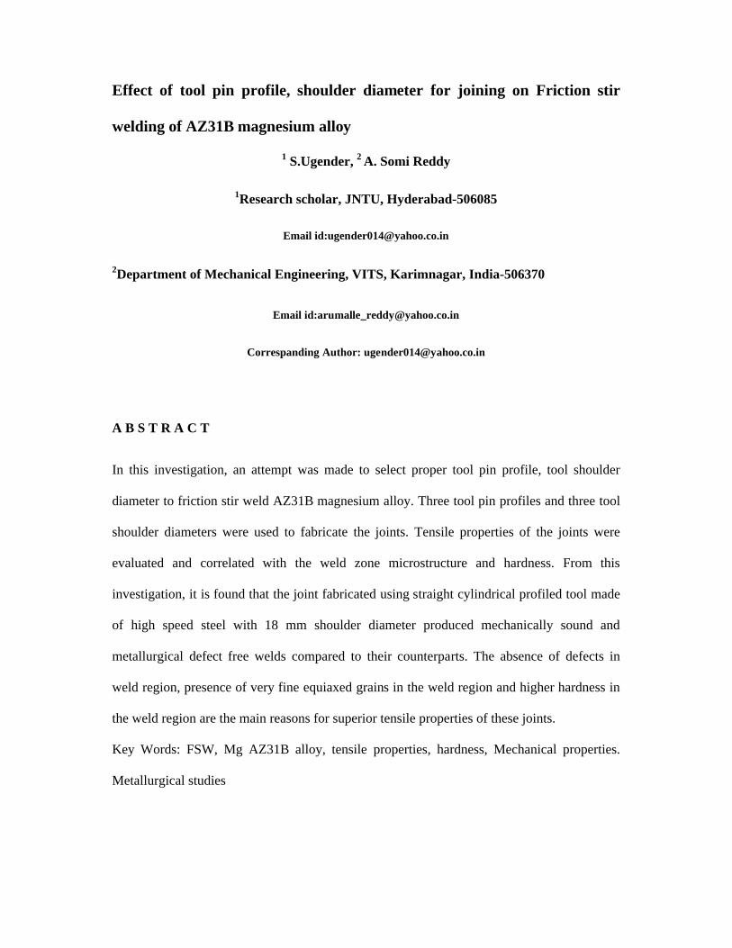
tools made of high speed steel are used to fabricate the joints. Three tool pin profiles (straight
cylindrical, triangular and square) and three shoulder diameters (15 mm, 18 mm, 21 mm)
were used to fabricate the joints. The chemical composition and mechanical properties of
base metal are presented in Tables 1a and 1b. The tool nomenclature is presented in Table 2.
A different type of tool pin profiles used in this Investigation is shown in Fig. 1. Various
nomenclature of tool is shown in Fig. 2. An indigenously designed and developed FSW
machine (15 hp; 3000 rpm; 25 KN) was used to fabricate the joints.
Table.1. Chemical composition (wt %) of base metal AZ31B magnesium alloy.

Al Mn Zn Cu Ni Si Fe Mg
3.0 2.0 1.0 0.05 0.005 0.1 0.005 Balance
Table.2.Mechanical Properties of Base Metal
Yield strength
(MPa)
Ultimate tensile
strength
(MPa)
Elongation
(%)
Reduction in
C/S area (%)
Hardness at 0.05
kg load (Hv)
171 215 14.7 14.3 69.3
Table. 3 Details FSW tool parameters and tools
Rotational speed(rpm) 1800
Welding speed(mm/min) 40
Pin length(mm) 4.5
Tool shoulder diameter(mm) 15,18,21
Axial force(KN) 4
Tilt angle(degrees) 2.5
Pin diameter 6
D/d Ratio of tool 2.5, 3.0, 3.5

The welded joints were sliced and then machined to the required dimension, according to the
ASTM E8 M-04 standard for sheet type material (i.e., 50 mm gauge length and 12.5 mm
gauge width). The tensile specimens were prepared to evaluate yield strength, tensile strength
and elongation. Tensile test was carried out in 100 KN, electro-mechanical controlled
universal testing machine (Make: FIE-Blue star, India; Model: UNITEK-94100). The 0.2%
offset yield strength and the percentage of elongation were evaluated. Rockwell hardness
testing machine (Make: SHIMADZU,INDIA, Model: HMV-2T) was employed for
measuring the hardness of the weld region with 0.05 kg load for 20 s.The specimens for
metallographic examination were sectioned to the required size and then polished using
different grades of emery papers. A standard reagent made of 4.2 g picric acid, 10 ml acetic
acid, 10 ml diluted water and 70 ml ethanol was used to reveal the microstructure of the
welded joints. Macro- and microstructuralanalysis was carried out using a light optical
microscope (Make: MEIJI, India; Model: MIL-7200) incorporated with an image analyzing
software (Metal Vision)
3. Results
3.1. Tensile properties
The tensile properties such as yield strength, tensile strength, percentage of elongation,
percentage of reduction in cross-sectional area and joint efficiency of friction stir welded
AZ31B magnesium alloy joints were evaluated. In each condition, three specimens were
tested and the average of three results is presented in Tables 1–3. The joint fabricated using
threaded pin profile exhibited superior tensile properties compared to the joints fabricated by
other pin profiles. Similarly, the joint fabricated with shoulder diameter of 18 mm exhibited
superior tensile properties compared to the joints fabricated by other two shoulder diameters.
In summary, the joint fabricated with straight cylindrical in profile tool made of high speed
steel with shoulder diameter of 18 mm (D/d = 3.0) exhibited superior tensile properties.

3.2. Macrographs
In fusion welding of magnesium alloys, the defects like porosity, hot crack etc. deteriorates
the weld quality and joint properties. Usually, friction stir welded joints are free from these
defects since there is no melting takes place during welding and the metals are joined in the
solid state itself due to the heat generated by the friction and flow of metal by the stirring
action. However, FSW joints are prone to other defects like pinhole, tunnel defect, piping
defect, kissing bond, cracks, etc. due to improper flow of metal and insufficient consolidation
of metal in the FSW region [8]. Hence, all the joints fabricated in this investigation were
analyzed at low magnification (10_) using optical microscope to reveal the quality of FSW
region. It is found that the joint fabricated with threaded pin profile is free from defects.
However, the joints fabricated by other pin profiles contain defects. Similarly, the joint
fabricated using a tool shoulder diameter of 18 mm (D/d = 3.0) is completely free from the
defects. The joint fabricated using high speed steel is completely free from the defects.
Invariably, all joints show wider upper surface than the lower surface because the upper
surface experienced an extreme deformation and frictional heat caused by contacting weld
specimens with a cylindrical tool shoulder.
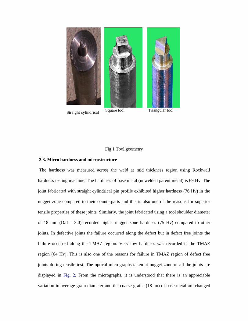
Straight cylindrical Square tool Triangular tool
Fig.1 Tool geometry
3.3. Micro hardness and microstructure
The hardness was measured across the weld at mid thickness region using Rockwell
hardness testing machine. The hardness of base metal (unwelded parent metal) is 69 Hv. The
joint fabricated with straight cylindrical pin profile exhibited higher hardness (76 Hv) in the
nugget zone compared to their counterparts and this is also one of the reasons for superior
tensile properties of these joints. Similarly, the joint fabricated using a tool shoulder diameter
of 18 mm (D/d = 3.0) recorded higher nugget zone hardness (75 Hv) compared to other
joints. In defective joints the failure occurred along the defect but in defect free joints the
failure occurred along the TMAZ region. Very low hardness was recorded in the TMAZ
region (64 Hv). This is also one of the reasons for failure in TMAZ region of defect free
joints during tensile test. The optical micrographs taken at nugget zone of all the joints are
displayed in Fig. 2. From the micrographs, it is understood that there is an appreciable
variation in average grain diameter and the coarse grains (18 lm) of base metal are changed

into fine grains in the nugget region. Hence, an attempt was made to measure the average
grain diameter of the weld metal region (nugget zone) of all the joints by applying Hein’s line
intercept method and measured grain sizes. The joint fabricated with threaded pin profile
contains finer grains (6.3 lm) along with more number of sub grains in the nugget region
compared to other joints .Similarly, the joint fabricated with shoulder diameter of 18 mm and
the joint fabricated with high carbon steel tool contain very fine grains in the nugget region
compared to their counterparts. The presence of very fine equated grains in the nugget region,
more number of sub grains and very clear grain boundaries are the reasons for better tensile
properties of these joints compared to their counterparts. To identify, the reason for failure in
TMAZ region, the detailed microstructure was taken in TMAZ region of both advancing and
retreating side (Fig. 2). From the micrographs, it is understood that there is an appreciable
difference in grain size (average grain diameter) in the nugget and thermo mechanically
affected zone (TMAZ). The grain size of TMAZ is coarser than the nugget region, because of
insufficient deformation and thermal exposure. Also, there is an appreciable variation in grain
size is observed in the retreating side (13 lm) compared to advancing side (15 lm) and this is
caused by the greater straining expected in this location. The similar observation was made
by Pareek et alin friction stir welding of AZ31B magnesium alloy. This is also another reason
for failure along the TMAZ region in the advancing side of defect free joints.

(b) Square
© Base metal (d) Triangular
Fig.2.Effect of tool pin profile on stir zone microstructure
D/d=2.5 D/d=3.0
D/d=3.5 Base metal
Fig.3.Effect of tool shoulder diameter on stir zone microstructure

4. Discussion
4.1. Effect of tool pin profiles
In case of straight cylindrical and tapered cylindrical pin profiles much of the material
movement takes place by simple extrusion and it seems to have no vertical motion of the
material which is apparently necessary to stabilize the rotational zone and to provide
sufficient deformation of material to obtain sound weld. Welds made with theses pin profiles
typically showed tunnel at the bottom (Table 7). Similar observation was made by McClure
et al. on FSW of 6061 aluminium alloy [9]. In triangular profiled tool, the frictional area tool
is about 50% smaller than that of the cylindrical pin tools. Since larger frictional area will
generate larger amount of friction between the probe side and the welding material is limited
to near three sharp edges, which is very smaller than that of other tools. heat, the friction heat
generated by the triangular probe might be smaller than that by the column tools.
Consequently, for the triangular prism tool, the bottom surface temperature is always lower
than the others, which produce tunnel at the bottom, due to lack of stirring in the friction stir
processing zone (Table 7). Similar observation was reported by Fujii et al. on FSW of 1050-
H24 aluminium alloy [6]. The screw thread will be beneficial to the heat generation, under
the same weld parameter; the pin with screw thread will generate more heat than the pin
without screw thread. More heat input can improve the flow of the plastic material. On the
other hand, the screw thread on the pin exerts an extra downward force that will be beneficial
to accelerate the flow of the plastic material. Material transports from the advanced side to
the retreated side, and goes around the pin, back to the advanced side. Without the screw
thread, material transfers insufficiently, and as the result, insufficient material comes back to
the advanced side; void defection will be generated at the advanced side [9]. Threaded pins
are found to assist in ensuring the plastically deformed work piece material is fully delivered
around the pin, and from the upper parts of the joint to the lower parts and vise versa. This

enhanced mixing enables the use of higher speeds and results in better quality, void free
welds (Table 7). Similar observation was made by Colligan et al. on FSW of 2519-T87
aluminium armour plate [8]. During stirring, square profile tool sweeps a large amount of
metal from the plasticized zone and results in an inhomogeneous structure and produce a
tunnel at the bottom (Table 7). Similar observation was reported by Boz et al. on FSW of
1080 aluminium alloy [10].Of the five tool pin profiles used in this investigation, the joints
fabricated using the threaded pin profile yielded defect free and fine grained nugget region
which led to the enhancement of hardness and tensile properties of the welded joints
4.2. Effect of tool shoulder diameter
From the above discussion, it is clear that the joint fabricated by threaded pin profile showed
superior tensile properties. Hence, threaded pin profiled tools were fabricated with varying
tool shoulder diameters (15, 18 and 21 mm) to study the effect of tool shoulder diameter on
tensile properties of FSW AZ31B magnesium alloy joints. The tool shoulder diameter is
having directly proportional relationship with the heat generation due to friction. If the
shoulder diameter is larger, then heat generation due to friction will be higher due to large
contact area and vice versa. In this investigation, it is observed that the larger tool shoulder
diameter (21 mm) led to wider contact area and resulted in coarse grains in the nugget region
and subsequently the tensile properties of the joints are deteriorated. It is also observed that
the smaller tool shoulder diameter (15 mm) lead to narrow contact area and resulted in less
frictional heat generation and hence the weld metal consolidation is not so good in the nugget
region. Of the three tool shoulder diameters used in this investigation, the joint fabricated
using 18 mm shoulder diameter (D/d = 3.0) yielded defect free and fine grained nugget region
which subsequently showed higher hardness and superior tensile properties (Table 5). Similar
observations were made by Elangovan and Balasubramanian [10] on FSW of AA6061
aluminium alloy.

5. Conclusions
In this investigation, an attempt was made to select proper tool pin profile, tool shoulder
diameter and tool material to friction stir weld AZ31B magnesium alloy. From this
investigation, the following important conclusions are derived: (1) the joints fabricated by
high speed steel tool with straight cylindrical pin profile and shoulder diameter of 18 mm
(D/d = 3.0) exhibited superior tensile properties compared to their counterparts.(2) The
absence of defects in nugget region, presence of very fine equiaxed grains in the nugget
region and the formation of more number of sub grains in nugget region are the main reasons
for higher hardness and subsequently for the superior tensile properties of the above joints.
6. References
[1] Afrin N, Chen DL, Cao X, Jahazi M. Microstructure and tensile properties of
friction stir welded AZ31B magnesium alloy. Mater Sci Eng A
2008;472:179–86.
[2] Mishra RS, Ma ZY. Friction stir welding and processing. Mater Sci Eng 2005;R
50:1–78.
[3] Rowe CED, Wayne Thomas. Advances in tooling materials for friction stir
welding. Technical report. Internet publication by TWI 13th January;
2005.
[4] Hidetoshi Fujii, Ling Cui, Masakatsu Maeda, Kiyoshi Nogi. Effect of tool shape
on mechanical properties and microstructure of friction stir welded aluminum
alloys. Mater Sci Eng A 2006;419:25–31.
[5] Scialpi A, De Filippis LAC, Cavaliere P. Influence of shoulder geometry on
microstructure and mechanical properties of friction stir welded 6082
aluminium alloy. Mater Des 2007;28:1124–9.
[6] Elangovan K, Balasubramanian V. Influences of pin profile and rotational speed

of the tool on the formation of friction stir processing zone in AA2219
aluminium alloy. Mater Sci Eng A 2007;459:7–18.
[7] Yan-hua Zhao, San-bao Lin, Lin Wu, Fu-xing Qu. The influence of pin geometry
on bonding and mechanical properties in friction stir weld 2014 Al alloy. Mater
Lett 2005;59:2948–52.
[8] Boz Mustafa, Kurt Adem. The influence of stirrer geometry on bonding and
mechanical properties in friction stir welding process. Mater Des
2004;25:343–7.
[9] Elangovan K, Balasubramanian V. Influences of tool pin profile and tool
shoulder diameter on the formation of friction stir processing zone in AA6061
aluminium alloy. Mater Des 2008;29(2):362–73.
[10] Kumar K, Satish Kailas V. The role of friction stir welding tool on material flow
and weld formation. Mater Sci Eng A 2008; 485:367–74.