pctest engineering laboratory, inc. sar evaluation … · samsung electronics, co. ltd. 06/08/15...
TRANSCRIPT

FCC ID: A3LSMN920V
SAR EVALUATION REPORT
Reviewed by:
Quality Manager
Document S/N: Test Dates: DUT Type: Page 1 of 109
0Y1506081067R1.A3L 06/08/15 – 06/22/15 Portable Handset © 2015 PCTEST Engineering Laboratory, Inc. REV 14.0 M 07/21/2014
Applicant Name: Date of Testing: Samsung Electronics, Co. Ltd. 06/08/15 –06/22/15 129, Samsung-ro, Maetan dong, Test Site/Location: Yeongtong-gu, Suwon-si PCTEST Lab, Columbia, MD, USA Gyeonggi-do 443-742, Korea Document Serial No.: 0Y1506081067-R1.A3L
FCC ID: A3LSMN920V
APPLICANT: SAMSUNG ELECTRONICS, CO. LTD.
DUT Type: Portable Handset Application Type: Certification
FCC Rule Part(s): CFR §2.1093 Model(s): SM-N920V
Note: This revised Test Report (S/N: 0Y1506081067-R1.A3L) supersedes and replaces the previously issued test report on the same subject device for the same type of testing as indicated. Please discard or destroy the previously issued test report(s) and dispose of it accordingly This wireless portable device has been shown to be capable of compliance for localized specific absorption rate (SAR) for uncontrolled environment/general population exposure limits specified in ANSI/IEEE C95.1-1992 and has been tested in accordance with the measurement procedures specified in Section 1.8 of this report; for North American frequency bands only. I attest to the accuracy of data. All measurements reported herein were performed by me or were made under my supervision and are correct to the best of my knowledge and belief. I assume full responsibility for the completeness of these measurements and vouch for the qualifications of all persons taking them. Test results reported herein relate only to the item(s) tested.
The SAR Tick is an initiative of the Mobile Manufacturers Forum (MMF). While a product may be considered eligible, use of the SAR Tick logo requires an agreement with the MMF. Further details can be obtained by emailing: [email protected].
1 gm Head (W/kg)
1 gm Body-Worn (W/kg)
1 gm Hotspot (W/kg)
10 gm Extremity (W/kg)
PCE GSM/GPRS/EDGE 850 824.20 - 848.80 MHz 0.18 0.41 1.00 < 0.1PCE GSM/GPRS/EDGE 1900 1850.20 - 1909.80 MHz 0.11 0.33 1.08 2.30PCE UMTS 850 826.40 - 846.60 MHz 0.18 0.36 0.59 < 0.1PCE UMTS 1900 1852.4 - 1907.6 MHz 0.19 0.55 1.05 2.77PCE Cell. CDMA/EVDO 824.70 - 848.31 MHz 0.21 0.49 0.97 < 0.1PCE PCS CDMA/EVDO 1851.25 - 1908.75 MHz 0.20 0.70 0.99 3.29PCE LTE Band 13 779.5 - 784.5 MHz 0.19 0.43 0.71 < 0.1PCE LTE Band 5 (Cell) 824.7 - 848.3 MHz 0.14 0.35 0.65 < 0.1PCE LTE Band 4 (AWS) 1710.7 - 1754.3 MHz 0.17 0.42 1.03 2.52PCE LTE Band 2 (PCS) 1850.7 - 1909.3 MHz 0.18 0.59 1.10 2.89DTS 2.4 GHz WLAN 2412 - 2462 MHz 0.23 0.12 0.12 < 0.1NII U-NII-1 5180 - 5240 MHz N/A N/A -1.00 N/ANII U-NII-2A 5260 - 5320 MHz 0.52 0.13 -1.00 0.66NII U-NII-2C 5500 - 5720 MHz 0.67 0.26 -1.00 1.26NII U-NII-3 5745 - 5825 MHz 0.58 0.26 0.26 < 0.1
DSS/DTS Bluetooth 2402 - 2480 MHz
1.16 1.08 1.48 3.83
SAR
Band & Mode Tx FrequencyEquipment
Class
Simultaneous SAR per KDB 690783 D01v01r03:N/A
PCTEST ENGINEERING LABORATORY, INC. 7185 Oakland Mills Road, Columbia, MD 21046 USA
Tel. +1.410.290.6652 / Fax +1.410.290.6654 http://www.pctestlab.com
SAR EVALUATION REPORT

FCC ID: A3LSMN920V
SAR EVALUATION REPORT
Reviewed by:
Quality Manager
Document S/N: Test Dates: DUT Type: Page 2 of 109
0Y1506081067R1.A3L 06/08/15 – 06/22/15 Portable Handset © 2015 PCTEST Engineering Laboratory, Inc. REV 14.0 M 07/21/2014
T A B L E O F C O N T E N T S
1 DEVICE UNDER TEST ................................................................................................................... 3
2 LTE INFORMATION ...................................................................................................................... 10
3 INTRODUCTION ........................................................................................................................... 11
4 DOSIMETRIC ASSESSMENT ...................................................................................................... 12
5 DEFINITION OF REFERENCE POINTS ...................................................................................... 13
6 TEST CONFIGURATION POSITIONS FOR HANDSETS ............................................................ 14
7 RF EXPOSURE LIMITS ................................................................................................................ 18
8 FCC MEASUREMENT PROCEDURES ........................................................................................ 19
9 RF CONDUCTED POWERS ......................................................................................................... 26
10 SYSTEM VERIFICATION .............................................................................................................. 71
11 SAR DATA SUMMARY ................................................................................................................. 75
12 FCC MULTI-TX AND ANTENNA SAR CONSIDERATIONS ......................................................... 89
13 SAR MEASUREMENT VARIABILITY ......................................................................................... 102
14 EQUIPMENT LIST ....................................................................................................................... 104
15 MEASUREMENT UNCERTAINTIES .......................................................................................... 105
16 CONCLUSION ............................................................................................................................. 107
17 REFERENCES ............................................................................................................................ 108
APPENDIX A: SAR TEST PLOTS APPENDIX B: SAR DIPOLE VERIFICATION PLOTS APPENDIX C: PROBE AND DIPOLE CALIBRATION CERTIFICATES APPENDIX D: SAR TISSUE SPECIFICATIONS
APPENDIX E: SAR SYSTEM VALIDATION
APPENDIX F: SAR TEST DIAGRAMS AND PHOTOGRAPHS
APPENDIX G: SENSOR TRIGGERING DATA SUMMARY

FCC ID: A3LSMN920V
SAR EVALUATION REPORT
Reviewed by:
Quality Manager
Document S/N: Test Dates: DUT Type: Page 3 of 109
0Y1506081067R1.A3L 06/08/15 – 06/22/15 Portable Handset © 2015 PCTEST Engineering Laboratory, Inc. REV 14.0 M 07/21/2014
1 D E V I C E U N D E R T E S T
1.1 Device Overview
1.2 Power Reduction for SAR
This device utilizes independent power reduction mechanisms for SAR compliance for the licensed transmitter and the WLAN transmitter. For the main transmitter, the device utilizes power reduction for some exposure and use conditions as outlined in Section 1.3.
Additionally, this device uses an independent single-step fixed level power reduction mechanism for WLAN operations during voice or VoIP held to ear scenarios. Per FCC Guidance, the held-to-ear exposure conditions were evaluated at reduced power according to the head SAR positions described in IEEE 1528.
The reduced powers for the power reduction mechanisms were confirmed via conducted power measurements at the RF port (See Section 9). Detailed descriptions of the mechanisms are included in the operational description.
GSM/GPRS/EDGE 850 Voice/Data 824.20 - 848.80 MHzGSM/GPRS/EDGE 1900 Voice/Data 1850.20 - 1909.80 MHz
UMTS 850 Voice/Data 826.40 - 846.60 MHzUMTS 1900 Voice/Data 1852.4 - 1907.6 MHz
Cell. CDMA/EVDO Voice/Data 824.70 - 848.31 MHzPCS CDMA/EVDO Voice/Data 1851.25 - 1908.75 MHz
LTE Band 13 Voice/Data 779.5 - 784.5 MHzLTE Band 5 (Cell) Voice/Data 824.7 - 848.3 MHzLTE Band 4 (AWS) Voice/Data 1710.7 - 1754.3 MHzLTE Band 2 (PCS) Voice/Data 1850.7 - 1909.3 MHz
2.4 GHz WLAN Data 2412 - 2462 MHzU-NII-1 Data 5180 - 5240 MHzU-NII-2A Data 5260 - 5320 MHzU-NII-2C Data 5500 - 5720 MHzU-NII-3 Data 5745 - 5825 MHz
Bluetooth Data 2402 - 2480 MHzNFC Data 13.56 MHzANT+ Data 2402 - 2480 MHzMST Data 1 - 8.3 kHz
Band & Mode Tx FrequencyOperating Modes

FCC ID: A3LSMN920V
SAR EVALUATION REPORT
Reviewed by:
Quality Manager
Document S/N: Test Dates: DUT Type: Page 4 of 109
0Y1506081067R1.A3L 06/08/15 – 06/22/15 Portable Handset © 2015 PCTEST Engineering Laboratory, Inc. REV 14.0 M 07/21/2014
1.3 RF Output Target Power Specifications This device operates using the following maximum and nominal output power specifications. SAR values were scaled to the maximum allowed power to determine compliance per KDB Publication 447498 D01v05.
Voice
(dBm)
1 TX Slot 1 TX Slots 2 TX Slots 3 TX Slots 4 TX Slots 1 TX Slots 2 TX Slots 3 TX Slots 4 TX Slots
Maximum 33.5 33.5 32.5 31.0 30.0 27.5 27.0 26.0 24.0
Nominal 33.0 33.0 32.0 30.5 29.5 27.0 26.5 25.5 23.5
Maximum 30.5 30.5 29.5 28.0 26.5 26.5 26.5 25.0 23.5
Nominal 30.0 30.0 29.0 27.5 26.0 26.0 26.0 24.5 23.0
Maximum 28.5 28.5 27.0 25.0 24.0 25.0 25.0 23.5 22.5
Nominal 28.0 28.0 26.5 24.5 23.5 24.5 24.5 23.0 22.0
Head, Body‐Worn, Hand
Hotspot, Hand
Mode / Band Exposure Condition(s)
Maximum
Reduced GSM/GPRS/EDGE 1900
Head, Body‐Worn, HotspotMaximum
Burst Average GMSK (dBm) Burst Average 8‐PSK (dBm)
GSM/GPRS/EDGE 1900
GSM/GPRS/EDGE 850
3GPP
WCDMA
3GPP
HSDPA
3GPP
HSUPA
Maximum 23.5 23.5 23.5
Nominal 23.0 23.0 23.0
Maximum 23.5 23.5 23.5
Nominal 23.0 23.0 23.0
Maximum 21.0 21.0 21.0
Nominal 20.5 20.5 20.5UMTS Band 2 (1900 MHz) Hotspot, HandReduced
Maximum
Maximum
Mode / Band Exposure Condition(s)
Head, Body‐Worn, Hotspot
Head, Body‐Worn, Hand
Modulated Average (dBm)
UMTS Band 2 (1900 MHz)
UMTS Band 5 (850 MHz)
Maximum
Nominal
Maximum
Nominal
Maximum
Nominal
Maximum
Nominal
21.5
21.0
Hand
HotspotPCS CDMA/EVDOReduced
Mode / Band Exposure Condition(s)
Maximum
Reduced
Maximum
Head, Body‐Worn, Hotspot
Head, Body‐Worn, Hand
PCS CDMA/EVDO23.0
Modulated Average
(dBm)
25.0
25.0
24.5PCS CDMA/EVDO
22.5
24.5Cell. CDMA/EVDO
Maximum
Nominal
Maximum
Nominal
Maximum
Nominal
Maximum
Nominal
Maximum
Nominal
Maximum
Nominal
Maximum
Nominal
21.0
20.5
Head, Body‐Worn, Hand
Hotspot, Hand22.5
22.0
Hand22.5
22.0
Head, Body‐Worn, Hotspot
Head, Body‐Worn, Hotspot
Mode / Band Exposure Condition(s)
LTE Band 4 (AWS)
LTE Band 2 (PCS)
LTE Band 2 (PCS) Hotspot
Reduced
Reduced
Reduced
Maximum
Maximum
Maximum
Maximum Head, Body‐Worn, Hand
24.5
24.5
24.0
24.0
24.0
24.0
Modulated Average
(dBm)
24.5LTE Band 13
LTE Band 4 (AWS)
LTE Band 2 (PCS)24.5
LTE Band 5 (Cell)
Maximum
Nominal
Maximum
Nominal
Maximum
Nominal
Maximum
Nominal
Maximum
Nominal
Maximum
Nominal
Maximum
Nominal
Maximum
Nominal
14.5 N/A
14.0 N/A
Reduced IEEE 802.11g (2.4 GHz) Head13.5 N/A
13.0 N/A
Reduced IEEE 802.11b (2.4 GHz) Head
Reduced IEEE 802.11n (2.4 GHz) Head
Mode / Band Exposure Condition(s)
Body‐worn, Hotspot
Body‐worn, Hotspot
Body‐worn, Hotspot
Body‐worn, Hand
Body‐worn, Hand
Maximum
Maximum
Maximum
Maximum
Maximum
Bluetooth
Bluetooth LEN/A
N/A
N/A
14.5 17.5
MIMO Operations
18.5 N/A
18.0 N/A
IEEE 802.11n (2.4 GHz)
Modulated Average (dBm)
SISO Operations
15.5 N/A
15.0
IEEE 802.11b (2.4 GHz)
IEEE 802.11g (2.4 GHz)
14.0 17.0
11.5
11.0
7.5
7.0
N/A
N/A
13.5 16.5
13.0 16.0
Maximum
Nominal
Maximum
Nominal
Maximum
Nominal
Maximum
Nominal
Maximum
Nominal
Maximum
Nominal
9.5 12.5
9.0 12.0 9.0 12.0 9.0 12.0
9.5 12.5
9.0 12.0
9.5 12.5
9.0 12.0
Reduced IEEE 802.11ac (5 GHz) Head9.5 12.5 9.5 12.5
Body‐worn, Hotspot, Hand
Body‐worn, Hotspot, Hand
Body‐worn, Hotspot, Hand
Mode / Band Exposure Condition(s)
IEEE 802.11a (5 GHz) Head
IEEE 802.11n (5 GHz) Head
Maximum
Maximum
Maximum
Reduced
Reduced
IEEE 802.11n (5 GHz)
IEEE 802.11ac (5 GHz)
IEEE 802.11a (5 GHz)
SISO Operations MIMO Operations
15.0 N/A
13.0 16.0
MIMO Operations
15.5 N/A
Modulated Average (dBm)
20 MHz Bandwidth 40 MHz Bandwidth 80 MHz Bandwidth
SISO Operations MIMO Operations SISO Operations
12.0 15.0
13.5 16.5 12.5 15.5
10.5 N/A
10.0 N/A
14.5
13.0 16.0 12.0 15.0 11.0 14.0
13.5 16.5 12.5 15.5 11.5
FCC ID: A3LSMN920V
SAR EVALUATION REPORT
Reviewed by:
Quality Manager
Document S/N: Test Dates: DUT Type: Page 5 of 109
0Y1506081067R1.A3L 06/08/15 – 06/22/15 Portable Handset © 2015 PCTEST Engineering Laboratory, Inc. REV 14.0 M 07/21/2014
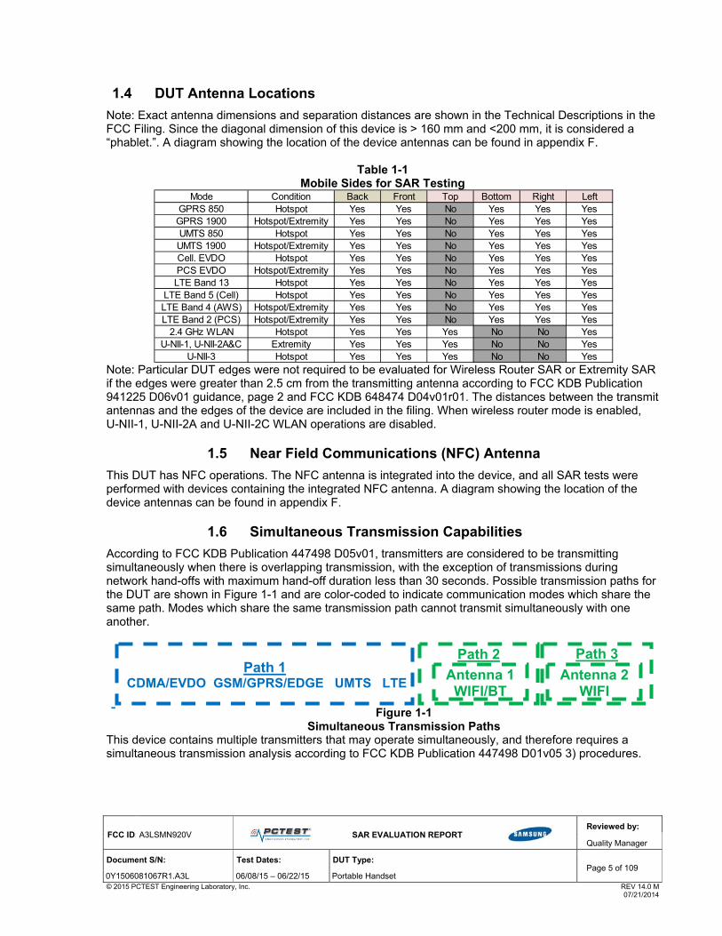
1.4 DUT Antenna Locations
Note: Exact antenna dimensions and separation distances are shown in the Technical Descriptions in the FCC Filing. Since the diagonal dimension of this device is > 160 mm and <200 mm, it is considered a “phablet.”. A diagram showing the location of the device antennas can be found in appendix F.
Table 1-1
Mobile Sides for SAR Testing
Note: Particular DUT edges were not required to be evaluated for Wireless Router SAR or Extremity SAR if the edges were greater than 2.5 cm from the transmitting antenna according to FCC KDB Publication 941225 D06v01 guidance, page 2 and FCC KDB 648474 D04v01r01. The distances between the transmit antennas and the edges of the device are included in the filing. When wireless router mode is enabled, U-NII-1, U-NII-2A and U-NII-2C WLAN operations are disabled.
1.5 Near Field Communications (NFC) Antenna
This DUT has NFC operations. The NFC antenna is integrated into the device, and all SAR tests were performed with devices containing the integrated NFC antenna. A diagram showing the location of the device antennas can be found in appendix F.
1.6 Simultaneous Transmission Capabilities
According to FCC KDB Publication 447498 D05v01, transmitters are considered to be transmitting simultaneously when there is overlapping transmission, with the exception of transmissions during network hand-offs with maximum hand-off duration less than 30 seconds. Possible transmission paths for the DUT are shown in Figure 1-1 and are color-coded to indicate communication modes which share the same path. Modes which share the same transmission path cannot transmit simultaneously with one another.
Figure 1-1
Simultaneous Transmission Paths This device contains multiple transmitters that may operate simultaneously, and therefore requires a simultaneous transmission analysis according to FCC KDB Publication 447498 D01v05 3) procedures.
Mode Condition Back Front Top Bottom Right LeftGPRS 850 Hotspot Yes Yes No Yes Yes YesGPRS 1900 Hotspot/Extremity Yes Yes No Yes Yes YesUMTS 850 Hotspot Yes Yes No Yes Yes YesUMTS 1900 Hotspot/Extremity Yes Yes No Yes Yes YesCell. EVDO Hotspot Yes Yes No Yes Yes YesPCS EVDO Hotspot/Extremity Yes Yes No Yes Yes YesLTE Band 13 Hotspot Yes Yes No Yes Yes Yes
LTE Band 5 (Cell) Hotspot Yes Yes No Yes Yes YesLTE Band 4 (AWS) Hotspot/Extremity Yes Yes No Yes Yes YesLTE Band 2 (PCS) Hotspot/Extremity Yes Yes No Yes Yes Yes
2.4 GHz WLAN Hotspot Yes Yes Yes No No YesU-NII-1, U-NII-2A&C Extremity Yes Yes Yes No No Yes
U-NII-3 Hotspot Yes Yes Yes No No Yes
Path 3
Path 2 Path 1
CDMA/EVDO GSM/GPRS/EDGE UMTS LTE Antenna 1 WIFI/BT
Antenna 2 WIFI

FCC ID: A3LSMN920V
SAR EVALUATION REPORT
Reviewed by:
Quality Manager
Document S/N: Test Dates: DUT Type: Page 6 of 109
0Y1506081067R1.A3L 06/08/15 – 06/22/15 Portable Handset © 2015 PCTEST Engineering Laboratory, Inc. REV 14.0 M 07/21/2014
Table 1-2 Simultaneous Transmission Scenarios
1. When the user utilizes multiple services in UMTS 3G mode it uses multi-Radio Access Bearer or multi-RAB. The power
control is based on a physical control channel (Dedicated Physical Control Channel [DPCCH]) and power control will be adjusted to meet the needs of both services. Therefore, the UMTS+WLAN scenario also represents the UMTS Voice/DATA + WLAN Hotspot scenario.
2. Per the manufacturer, WIFI Direct is not expected to be used in conjunction with a held-to-ear or body-worn accessory voice call. Therefore, there is no simultaneous transmission scenarios involving WIFI direct beyond that listed in the above table.
3. 5 GHz Wireless Router is only supported for the U-NII-3 by S/W, therefore U-NII-1, U-NII2A, and U-NII2C were not evaluated for wireless router conditions.
4. This device supports 2x2 MIMO Tx for IEEE 802.11n/ac. Each WLAN antenna can transmit independently or together when operating in MIMO mode.
5. 2.4 GHz WLAN, 5 GHz WLAN, and 2.4 GHz Bluetooth that share the same antenna path cannot transmit simultaneously. 6. All licensed modes share the same antenna and cannot transmit simultaneously. 7. This device supports VoLTE.
No. Capable Transmit Configuration HeadBody-WornAccessory
WirelessRouter
Extremity Notes
1 1x CDMA voice + 2.4 GHz WI-FI Yes Yes N/A Yes 2 1x CDMA voice + 5 GHz WI-FI Yes Yes N/A Yes 3 1x CDMA voice + 2.4 GHz Bluetooth N/A Yes N/A Yes 4 1x CDMA voice + 2.4 GHz WIFI MIMO Yes Yes N/A Yes5 1x CDMA voice + 5 GHz WIFI MIMO Yes Yes N/A Yes6 1x CDMA voice + 2.4 GHz WIFI Ant 1 + 5 GHz WIFI Ant 2 Yes Yes N/A Yes7 1x CDMA voice + 2.4 GHz WIFI Ant 2 + 5 GHz WIFI Ant 1 Yes Yes N/A Yes8 GSM voice + 2.4 GHz WI-FI Yes Yes N/A Yes 9 GSM voice + 5 GHz WI-FI Yes Yes N/A Yes 10 GSM voice + 2.4 GHz Bluetooth N/A Yes N/A Yes 11 GSM voice + 2.4 GHz WIFI MIMO Yes Yes N/A Yes12 GSM voice + 5 GHz WIFI MIMO Yes Yes N/A Yes13 GSM voice + 2.4 GHz WIFI Ant 1 + 5 GHz WIFI Ant 2 Yes Yes N/A Yes14 GSM voice + 2.4 GHz WIFI Ant 2 + 5 GHz WIFI Ant 1 Yes Yes N/A Yes15 UMTS + 2.4 GHz WI-FI Yes Yes Yes Yes 16 UMTS + 5 GHz WI-FI Yes Yes Yes Yes 17 UMTS + 2.4 GHz Bluetooth N/A Yes N/A Yes 18 UMTS + 2.4 GHz WIFI MIMO Yes Yes Yes Yes19 UMTS + 5 GHz WIFI MIMO Yes Yes Yes Yes20 UMTS + 2.4 GHz WIFI Ant 1 + 5 GHz WIFI Ant 2 Yes Yes Yes Yes21 UMTS + 2.4 GHz WIFI Ant 2 + 5 GHz WIFI Ant 1 Yes Yes Yes Yes22 LTE + 2.4 GHz WI-FI Yes Yes Yes Yes23 LTE + 5 GHz WI-FI Yes Yes Yes Yes24 LTE + 2.4 GHz Bluetooth N/A Yes N/A Yes25 LTE + 2.4 GHz WIFI MIMO Yes Yes Yes Yes26 LTE + 5 GHz WIFI MIMO Yes Yes Yes Yes27 LTE + 2.4 GHz WIFI Ant 1 + 5 GHz WIFI Ant 2 Yes Yes Yes Yes28 LTE + 2.4 GHz WIFI Ant 2 + 5 GHz WIFI Ant 1 Yes Yes Yes Yes29 CDMA/EVDO data + 2.4 GHz WI-FI Yes* Yes* Yes Yes *-Pre-installed VOIP applications are considered30 CDMA/EVDO data + 5 GHz WI-FI Yes* Yes* Yes Yes *-Pre-installed VOIP applications are considered31 CDMA/EVDO data + 2.4 GHz Bluetooth N/A Yes* N/A Yes *-Pre-installed VOIP applications are considered32 CDMA/EVDO data + 2.4 GHz WIFI MIMO Yes* Yes* Yes Yes *-Pre-installed VOIP applications are considered33 CDMA/EVDO data + 5 GHz WIFI MIMO Yes* Yes* Yes Yes *-Pre-installed VOIP applications are considered34 CDMA/EVDO data + 2.4 GHz WIFI Ant 1 + 5 GHz WIFI Ant 2 Yes* Yes* Yes Yes *-Pre-installed VOIP applications are considered35 CDMA/EVDO data + 2.4 GHz WIFI Ant 2 + 5 GHz WIFI Ant 1 Yes* Yes* Yes Yes *-Pre-installed VOIP applications are considered36 GPRS/EDGE + 2.4 GHz WI-FI N/A N/A Yes Yes37 GPRS/EDGE + 5 GHz WI-FI N/A N/A Yes Yes38 GRPS/EDGE + 2.4 GHz WIFI MIMO N/A N/A Yes Yes39 GRPS/EDGE + 5 GHz WIFI MIMO N/A N/A Yes Yes40 GRPS/EDGE + 2.4 GHz WIFI Ant 1 + 5 GHz WIFI Ant 2 N/A N/A Yes Yes41 GRPS/EDGE + 2.4 GHz WIFI Ant 2 + 5 GHz WIFI Ant 1 N/A N/A Yes Yes42 GSM voice + 2.4 GHz WIFI Ant 1 + 5 GHz WIFI Ant 1 N/A N/A N/A N/A Not Supported by HW43 GSM voice + 2.4 GHz WIFI Ant 2 + 5 GHz WIFI Ant 2 N/A N/A N/A N/A Not Supported by HW44 1x CDMA voice + 2.4 GHz WIFI Ant 1 + 5 GHz WIFI Ant 1 N/A N/A N/A N/A Not Supported by HW45 1x CDMA voice + 2.4 GHz WIFI Ant 2 + 5 GHz WIFI Ant 2 N/A N/A N/A N/A Not Supported by HW46 UMTS + 2.4 GHz WIFI Ant 1 + 5 GHz WIFI Ant 1 N/A N/A N/A N/A Not Supported by HW47 UMTS + 2.4 GHz WIFI Ant 2 + 5 GHz WIFI Ant 2 N/A N/A N/A N/A Not Supported by HW48 LTE + 2.4 GHz WIFI Ant 1 + 5 GHz WIFI Ant 1 N/A N/A N/A N/A Not Supported by HW49 LTE + 2.4 GHz WIFI Ant 2 + 5 GHz WIFI Ant 2 N/A N/A N/A N/A Not Supported by HW50 GPRS/EDGE + 2.4 GHz WIFI Ant 1 + 5 GHz WIFI Ant 1 N/A N/A N/A N/A Not Supported by HW51 GPRS/EDGE + 2.4 GHz WIFI Ant 2 + 5 GHz WIFI Ant 2 N/A N/A N/A N/A Not Supported by HW52 CDMA/EVDO data + 2.4 GHz WIFI Ant 1 + 5 GHz WIFI Ant 1 N/A N/A N/A N/A Not Supported by HW53 CDMA/EVDO data + 2.4 GHz WIFI Ant 2 + 5 GHz WIFI Ant 2 N/A N/A N/A N/A Not Supported by HW

FCC ID: A3LSMN920V
SAR EVALUATION REPORT
Reviewed by:
Quality Manager
Document S/N: Test Dates: DUT Type: Page 7 of 109
0Y1506081067R1.A3L 06/08/15 – 06/22/15 Portable Handset © 2015 PCTEST Engineering Laboratory, Inc. REV 14.0 M 07/21/2014
1.7 SAR Test Exclusions Applied
(A) WIFI/BT Since Wireless Router operations are not allowed by the chipset firmware using U-NII-1, U-NII-2A & U-NII-2C WIFI, only 2.4 GHz and U-NII-3 WIFI Hotspot SAR tests and combinations are considered for SAR with respect to Wireless Router configurations according to FCC KDB 941225 D01v03. Since U-NII-1 and U-NII-2A bands have the same maximum output power and the highest reported SAR for U-NII-2A is less than 1.2 W/kg for 1 gram SAR and less than 3.0 W/kg for 10 gram SAR, SAR is not required for U-NII-1 band according to FCC KDB 248227 D01v02r01.
This device supports IEEE 802.11ac with the following features:
a) Up to 80 MHz Bandwidth only b) No aggregate channel configurations c) 2 Tx antenna output d) 256 QAM is supported e) Band gap channels are supported f) TDWR channels are supported
Per FCC KDB 447498 D01v05, the 1g SAR exclusion threshold for distances <50mm is defined by the following equation:
Based on the maximum conducted power of Bluetooth (rounded to the nearest mW) and the antenna to user separation distance, body-worn Bluetooth SAR was not required; [(14/15)* √2.480] = 1.5< 3.0. Per KDB Publication 447498 D01v05, the maximum power of the channel was rounded to the nearest mW before calculation. Per FCC KDB 447498 D01v05, the 10g SAR exclusion threshold for distances <50mm is defined by the following equation:
Based on the maximum conducted power of Bluetooth (rounded to the nearest mW) and the antenna to user separation distance, extremity Bluetooth SAR was not required; [(14/ 5)* √2.480] = 4.4< 7.5. Per KDB Publication 447498 D01v05, the maximum power of the channel was rounded to the nearest mW before calculation.
Per FCC KDB Publication 648474 D04v01r01, this device is considered a "phablet" since the diagonal dimension is greater than 160mm and less than 200mm. Extremity SAR tests are required when wireless router mode does not apply or if wireless router 1g SAR > 1.2 W/kg.
∗ 7.5
FCC ID: A3LSMN920V
SAR EVALUATION REPORT
Reviewed by:
Quality Manager
Document S/N: Test Dates: DUT Type: Page 8 of 109
0Y1506081067R1.A3L 06/08/15 – 06/22/15 Portable Handset © 2015 PCTEST Engineering Laboratory, Inc. REV 14.0 M 07/21/2014
(B) Licensed Transmitter(s)
GSM/GPRS/EDGE DTM is not supported for US bands. Therefore, the GSM Voice modes in this report do not transmit simultaneously with GPRS/EDGE Data.
This device is only capable of QPSK HSUPA in the uplink. Therefore, no additional SAR tests are required beyond that described for devices with HSUPA in KDB 941225 D01v02.
LTE SAR for the higher modulations and lower bandwidths were not tested since the maximum average output power of all required channels and configurations was not more than 0.5 dB higher than the highest bandwidth; and the reported LTE SAR for the highest bandwidth was less than 1.45 W/kg for all configurations according to FCC KDB 941225 D05v02r03.
This device supports inter-band and intra-band LTE Carrier Aggregation (CA) in the downlink only. All uplink communications are identical to Release 8 specifications. Per FCC KDB Publication 941225 D05A v01r01, SAR for LTE CA operations was not needed since the maximum average output power in LTE CA mode was not >0.25 dB higher than the maximum output power when downlink carrier aggregation was inactive.
Per FCC KDB Publication 648474 D04v01r01, this device is considered a "phablet" since the diagonal dimension is greater than 160mm and less than 200mm. Extremity SAR tests are required when wireless router mode does not apply or if wireless router 1g SAR > 1.2 W/kg. For some modes, Extremity SAR was additionally evaluated at maximum output power due to reduced power. (See Section 6.8 for more information)
1.8 Guidance Applied
IEEE 1528-2003 FCC KDB Publication 941225 D01v03, D0-5v02r03, D05Av01, D06v02 (2G/3G/4G and Hotspot) FCC KDB Publication 248227 D01v02r01 (SAR Considerations for 802.11 Devices) FCC KDB Publication 447498 D01v05r02 (General SAR Guidance) FCC KDB Publication 865664 D01v01r03, D02v01r01 (SAR Measurements up to 6 GHz) FCC KDB Publication 648474 D03-D04 (Phablet Procedures) October 2013 TCB Workshop Notes (GPRS Testing Considerations)

FCC ID: A3LSMN920V
SAR EVALUATION REPORT
Reviewed by:
Quality Manager
Document S/N: Test Dates: DUT Type: Page 9 of 109
0Y1506081067R1.A3L 06/08/15 – 06/22/15 Portable Handset © 2015 PCTEST Engineering Laboratory, Inc. REV 14.0 M 07/21/2014
1.9 Device Serial Numbers
Several samples with identical hardware were used to support SAR testing. The manufacturer has confirmed that the device(s) tested have the same physical, mechanical and thermal characteristics and are within operational tolerances expected for production units.
Head Serial Number
Body-Worn Serial Number
Hotspot Serial Number
Extremity Maximum
Power Serial Number
Extremity Reduced Power Serial Number
GSM/GPRS/EDGE 850 ADDBE ADDBE ADDBE - -GSM/GPRS/EDGE 1900 ADDBE ADDBE ADFB5 ADDBE ADFB5
UMTS 850 ADDBE ADDBE ADDBE - -UMTS 1900 ADDBE ADDBE ADFB5 ADDBE ADFB5
Cell. CDMA/EVDO AC31E AC31E AC31E - -PCS CDMA/EVDO AC31E/AD7CE AC31E AD7CE AC31E ABAAE
LTE Band 13 AB613 AB613 AB613 - -LTE Band 5 (Cell) AB613 AB613 AB613 - -LTE Band 4 (AWS) AB613 AB613 AC258 AB613 AC258LTE Band 2 (PCS) AB613 AB613 AD7CE AB613 AC258
2.4 GHz WLAN ABAEB ABAEB ABAEB - -5 GHz WLAN ABAEB ABAEB ABAEB - ABAEB

FCC ID: A3LSMN920V
SAR EVALUATION REPORT
Reviewed by:
Quality Manager
Document S/N: Test Dates: DUT Type: Page 10 of 109
0Y1506081067R1.A3L 06/08/15 – 06/22/15 Portable Handset © 2015 PCTEST Engineering Laboratory, Inc. REV 14.0 M 07/21/2014
2 L T E I N F O R M A T I O N
Low Mid High
782 (23230)
782 (23230)
836.5 (20525)
836.5 (20525)
836.5 (20525)
836.5 (20525)
1732.5 (20175)
1732.5 (20175)
1732.5 (20175)
1732.5 (20175)1732.5 (20175)
1732.5 (20175)
1850.7 (18607) 1880 (18900) 1909.3 (19193)
1851.5 (18615) 1880 (18900) 1908.5 (19185)
1852.5 (18625) 1880 (18900) 1907.5 (19175)
1855 (18650) 1880 (18900) 1905 (19150)1857.5 (18675) 1880 (18900) 1902.5 (19125)
1860 (18700) 1880 (18900) 1900 (19100)
LTE Information
6QPSK, 16QAM
YES
YES
LTE Band 2 (PCS): 1.4 MHz, 3 MHz, 5 MHz, 10 MHz, 15 MHz, 20 MHzLTE Band 4 (AWS): 1.4 MHz, 3 MHz, 5 MHz, 10 MHz, 15 MHz, 20 MHz
LTE Band 5 (Cell): 1.4 MHz, 3 MHz, 5 MHz, 10 MHzLTE Band 13: 5 MHz, 10 MHz
LTE Band 2 (PCS) (1850.7 - 1909.3 MHz)
LTE Band 4 (AWS) (1710.7 - 1754.3 MHz)
LTE Band 5 (Cell) (824.7 - 848.3 MHz)LTE Band 13 (779.5 - 784.5 MHz)
Channel Numbers and Frequencies (MHz)
Modulations Supported in UL
LTE Band 2 (PCS): 3 MHz
LTE Band 4 (AWS): 1.4 MHz
LTE Band 2 (PCS): 5 MHz
LTE Band 5 (Cell): 3 MHz
LTE Band 5 (Cell): 5 MHz
LTE Band 5 (Cell): 10 MHz
LTE Carrier Aggregation Additional Information
A-MPR (Additional MPR) disabled for SAR Testing?
UE Category
LTE MPR Permanently implemented per 3GPP TS 36.101 section 6.2.3~6.2.5? (manufacturer attestation to be provided)
LTE Carrier Aggregation Possible Combinations
FCC ID
Form FactorFrequency Range of each LTE transmission band
LTE Band 13: 5 MHz
LTE Band 4 (AWS): 3 MHz
LTE Band 4 (AWS): 5 MHz
LTE Band 5 (Cell): 1.4 MHz
Channel Bandwidths
LTE Band 2 (PCS): 20 MHzLTE Band 2 (PCS): 15 MHz
LTE Band 13: 10 MHz
LTE Band 2 (PCS): 10 MHz
LTE Band 4 (AWS): 10 MHz
LTE Band 4 (AWS): 15 MHzLTE Band 4 (AWS): 20 MHz
LTE Band 2 (PCS): 1.4 MHz
779.5 (23205)
Portable Handset
A3LSMN920V
784.5 (23255)
844 (20600)
824.7 (20407)
825.5 (20415)
826.5 (20425)
829 (20450)
782 (23230) 782 (23230)
1754.3 (20393)1710.7 (19957)
1711.5 (19965)
1712.5 (19975)
848.3 (20643)
847.5 (20635)
846.5 (20625)
The technical description includes all the possible carrier aggregation combinations
This device does not support full CA features on 3GPP Release 10. It supports a maximum of 2 carriers in the downlink. All uplink communications are identical to the
Release 8 Specifications. Uplink communications are done on the PCC. Due to carrier capability, only the combinations listed above are supported. The following
LTE Release 10 Features are not supported: Relay, HetNet, Enhanced MIMO, eICI, WIFI Offloading, MDH, eMBMA, Cross-Carrier Scheduling, Enhanced SC-FDMA.
1753.5 (20385)
1752.5 (20375)
1750 (20350)1747.5 (20325)
1745 (20300)
1715 (20000)1717.5 (20025)
1720 (20050)
FCC ID: A3LSMN920V
SAR EVALUATION REPORT
Reviewed by:
Quality Manager
Document S/N: Test Dates: DUT Type: Page 11 of 109
0Y1506081067R1.A3L 06/08/15 – 06/22/15 Portable Handset © 2015 PCTEST Engineering Laboratory, Inc. REV 14.0 M 07/21/2014
3 I N T R O D U C T I O N
The FCC and Industry Canada have adopted the guidelines for evaluating the environmental effects of radio frequency (RF) radiation in ET Docket 93-62 on Aug. 6, 1996 and Health Canada Safety Code 6 to protect the public and workers from the potential hazards of RF emissions due to FCC-regulated portable devices. [1] The safety limits used for the environmental evaluation measurements are based on the criteria published by the American National Standards Institute (ANSI) for localized specific absorption rate (SAR) in IEEE/ANSI C95.1-1992 Standard for Safety Levels with Respect to Human Exposure to Radio Frequency Electromagnetic Fields, 3 kHz to 300 GHz [3] and Health Canada RF Exposure Guidelines Safety Code 6 [22]. The measurement procedure described in IEEE/ANSI C95.3-2002 Recommended Practice for the Measurement of Potentially Hazardous Electromagnetic Fields - RF and Microwave [4] is used for guidance in measuring the Specific Absorption Rate (SAR) due to the RF radiation exposure from the Equipment Under Test (EUT). These criteria for SAR evaluation are similar to those recommended by the International Committee for Non-Ionizing Radiation Protection (ICNIRP) in Biological Effects and Exposure Criteria for Radiofrequency Electromagnetic Fields,” Report No. Vol 74. SAR is a measure of the rate of energy absorption due to exposure to an RF transmitting source. SAR values have been related to threshold levels for potential biological hazards.
3.1 SAR Definition
Specific Absorption Rate is defined as the time derivative (rate) of the incremental energy (dU) absorbed by (dissipated in) an incremental mass (dm) contained in a volume element (dV) of a given density (). It is also defined as the rate of RF energy absorption per unit mass at a point in an absorbing body (see Equation 3-1).
Equation 3-1 SAR Mathematical Equation
SARd
dt
dU
dm
d
dt
dU
dv
SAR is expressed in units of Watts per Kilogram (W/kg).
2E
SAR
where: = conductivity of the tissue-simulating material (S/m) = mass density of the tissue-simulating material (kg/m3) E = Total RMS electric field strength (V/m)
NOTE: The primary factors that control rate of energy absorption were found to be the wavelength of the incident field in relation to the dimensions and geometry of the irradiated organism, the orientation of the organism in relation to the polarity of field vectors, the presence of reflecting surfaces, and whether conductive contact is made by the organism with a ground plane.[6]

FCC ID: A3LSMN920V
SAR EVALUATION REPORT
Reviewed by:
Quality Manager
Document S/N: Test Dates: DUT Type: Page 12 of 109
0Y1506081067R1.A3L 06/08/15 – 06/22/15 Portable Handset © 2015 PCTEST Engineering Laboratory, Inc. REV 14.0 M 07/21/2014
4 D O S I M E T R I C A S S E S S M E N T
4.1 Measurement Procedure
The evaluation was performed using the following procedure compliant to FCC KDB Publication 865664 D01v01 and IEEE 1528-2013:
1. The SAR distribution at the exposed side of the head or body was measured at a distance no greater than 5.0 mm from the inner surface of the shell. The area covered the entire dimension of the device-head and body interface and the horizontal grid resolution was determined per FCC KDB Publication 865664 D01v01 (See Table 4-1) and IEEE 1528-2013.
2. The point SAR measurement was taken at the maximum SAR region determined from Step 1 to enable the monitoring of SAR fluctuations/drifts during the 1g/10g cube evaluation. SAR at this fixed point was measured and used as a reference value.
3. Based on the area scan data, the peak of the region with maximum SAR was determined by spline interpolation. Around this point, a volume was assessed according to the measurement resolution and volume size requirements of FCC KDB Publication 865664 D01v01 (See Table 4-1) and IEEE 1528-2013. On the basis of this data set, the spatial peak SAR value was evaluated with the following procedure (see references or the DASY manual online for more details):
a. SAR values at the inner surface of the phantom are extrapolated from the measured values along the line away from the surface with spacing no greater than that in Table 4-1. The extrapolation was based on a least-squares algorithm. A polynomial of the fourth order was calculated through the points in the z-axis (normal to the phantom shell).
b. After the maximum interpolated values were calculated between the points in the cube, the SAR was averaged over the spatial volume (1g or 10g) using a 3D-Spline interpolation algorithm. The 3D-spline is composed of three one-dimensional splines with the “Not a knot” condition (in x, y, and z directions). The volume was then integrated with the trapezoidal algorithm. One thousand points (10 x 10 x 10) were obtained through interpolation, in order to calculate the averaged SAR.
c. All neighboring volumes were evaluated until no neighboring volume with a higher average value was found.
4. The SAR reference value, at the same location as step 2, was re-measured after the zoom scan was complete to calculate the SAR drift. If the drift deviated by more than 5%, the SAR test and drift measurements were repeated.
Table 4-1 Area and Zoom Scan Resolutions per FCC KDB Publication 865664 D01v01*
*Also compliant to IEEE 1528-2013 Table 6
Uniform Grid
∆zzoom(n) ∆zzoom(1)* ∆zzoom(n>1)*
≤ 2 GHz ≤ 15 ≤ 8 ≤ 5 ≤ 4 ≤ 1.5*∆zzoom(n‐1) ≥ 30
2‐3 GHz ≤ 12 ≤ 5 ≤ 5 ≤ 4 ≤ 1.5*∆zzoom(n‐1) ≥ 30
3‐4 GHz ≤ 12 ≤ 5 ≤ 4 ≤ 3 ≤ 1.5*∆zzoom(n‐1) ≥ 28
4‐5 GHz ≤ 10 ≤ 4 ≤ 3 ≤ 2.5 ≤ 1.5*∆zzoom(n‐1) ≥ 25
5‐6 GHz ≤ 10 ≤ 4 ≤ 2 ≤ 2 ≤ 1.5*∆zzoom(n‐1) ≥ 22
Minimum Zoom Scan
Volume (mm)
(x,y,z)
Maximum Zoom Scan Spatial
Resolution (mm)
Graded GridFrequency
Maximum Area Scan
Resolution (mm)
(∆xarea, ∆yarea)
Maximum Zoom Scan
Resolution (mm)
(∆xzoom, ∆yzoom)
Figure 4-1 Sample SAR Area
Scan

FCC ID
Docume
0Y15060© 2015 P
5
Figurepoint referethe enFigureReferLine, perpephant
Two ithe holocateFigurepoint.the haboth t
: A3LSMN920V
ent S/N:
081067R1.A3L PCTEST Engineering L
D E F I
e 5-2 shows t“M” is the refe
ence point (ERntrance to thee 5-1. The plrence Plane. is not perpen
endicular to thtom shell to fa
maginary lineorizontal line. ed along the “e 5-3). The a The test devandset at its tthe left and rig
Test Date
06/08/15 Laboratory, Inc.
N I T I O N
5.1 EA
the front, backerence point fRP), and “REe ear canal (Eane passing tThe line N-F
ndicular to thehe N-F line. Bacilitate hands
5.2 HA
es on the han The test dev
“vertical centeacoustic outpuvice was positop and bottomght head pha
Fron
Handset V
es: D
– 06/22/15 P
O F R E F
R REFERE
k and side viefor the center” is the right E
EEC) along ththrough the tw(Neck-Front)
e reference plaBoth N-F and set positionin
ANDSET RE
dset were estvice was placerline” on the ut was than loitioned so tham edges, posntoms on the
nt, back and
Vertical Cent
SAR EVALUA
DUT Type:
ortable Handset
E R E N C E
ENCE POIN
ews of the SAr of the mouthERP. The ERe B-M line (Bwo ear canals), also called tane (see FiguB-M lines areg [5].
EFERENCE
tablished: theced in a normafront of the d
ocated at the at the “verticalsitioning the “e ear referenc
Figure 5-2side view of
Figure 5-3ter & Horizon
ATION REPORT
E P O I N T
NT
AM Twin Phanh, “LE” is the lRP is 15mm pack-Mouth), as and M is dethe Referenceure 5-1). Linee marked on t
E POINTS
e vertical cental operating pevice alignedsame level asl centerline” wear referencee point.
2 f SAM Twin P
3 ntal Line Refe
S
ntom. The left ear
posterior to as shown in
efined as the e Pivoting e B-M is the external
terline and position with td to the “ear res the center owas bisecting e point” on the
Phantom
erence Point
Revie
Qualit
Page
he acoustic oeference poinof the ear refethe front surf
e outer surfac
ts
FigurClose-Up
of E
ewed by:
ty Manager
13 of 109
REV 14.0 M 07/21/2014
output nt” (See erence face of ce of the
re 5-1 Side view
ERP

FCC ID: A3LSMN920V
SAR EVALUATION REPORT
Reviewed by:
Quality Manager
Document S/N: Test Dates: DUT Type: Page 14 of 109
0Y1506081067R1.A3L 06/08/15 – 06/22/15 Portable Handset © 2015 PCTEST Engineering Laboratory, Inc. REV 14.0 M 07/21/2014
6 T E S T C O N F I G U R A T I O N P O S I T I O N S F O R H A N D S E T S
6.1 Device Holder
The device holder is made out of low-loss POM material having the following dielectric parameters: relative permittivity ε = 3 and loss tangent δ = 0.02.
6.2 Positioning for Cheek
1. The test device was positioned with the device close to the surface of the phantom such that point A is on the (virtual) extension of the line passing through points RE and LE on the phantom (see Figure 6-1), such that the plane defined by the vertical center line and the horizontal line of the phone is approximately parallel to the sagittal plane of the phantom.
Figure 6-1 Front, Side and Top View of Cheek Position
2. The handset was translated towards the phantom along the line passing through RE & LE until
the handset touches the pinna. 3. While maintaining the handset in this plane, the handset was rotated around the LE-RE line until
the vertical centerline was in the reference plane. 4. The phone was then rotated around the vertical centerline until the phone (horizontal line) was
symmetrical was respect to the line NF. 5. While maintaining the vertical centerline in the reference plane, keeping point A on the line
passing through RE and LE, and maintaining the device contact with the ear, the device was rotated about the NF line until any point on the handset made contact with a phantom point below the ear (cheek) (See Figure 6-2).
6.3 Positioning for Ear / 15º Tilt
With the test device aligned in the “Cheek Position”:
1. While maintaining the orientation of the phone, the phone was retracted parallel to the reference plane far enough to enable a rotation of the phone by 15degrees.
2. The phone was then rotated around the horizontal line by 15 degrees. 3. While maintaining the orientation of the phone, the phone was moved parallel to the reference
plane until any part of the handset touched the head. (In this position, point A was located on the line RE-LE). The tilted position is obtained when the contact is on the pinna. If the contact was at any location other than the pinna, the angle of the phone would then be reduced. In this situation, the tilted position was obtained when any part of the phone was in contact of the ear as well as a second part of the phone was in contact with the head (see Figure 6-2).

FCC ID: A3LSMN920V
SAR EVALUATION REPORT
Reviewed by:
Quality Manager
Document S/N: Test Dates: DUT Type: Page 15 of 109
0Y1506081067R1.A3L 06/08/15 – 06/22/15 Portable Handset © 2015 PCTEST Engineering Laboratory, Inc. REV 14.0 M 07/21/2014
Figure 6-2 Front, Side and Top View of Ear/15º Tilt
Position
Figure 6-3
Side view w/ relevant markings
6.4 Body-Worn Accessory Configurations
Body-worn operating configurations are tested with the belt-clips and holsters attached to the device and positioned against a flat phantom in a normal use configuration (see Figure 6-4). Per FCC KDB Publication 648474 D04v01, Body-worn accessory exposure is typically related to voice mode operations when handsets are carried in body-worn accessories. The body-worn accessory procedures in FCC KDB Publication 447498 D01v05 should be used to test for body-worn accessory SAR compliance, without a headset connected to it. This enables the test results for such configuration to be compatible with that required for hotspot mode when the body-worn accessory test separation distance is greater than or equal to that required for hotspot mode, when applicable. When the reported SAR for a body-worn accessory, measured without a headset connected to the handset, is > 1.2 W/kg, the highest reported SAR configuration for that wireless mode and frequency band should be repeated for that body-worn accessory with a headset attached to the handset. Accessories for Body-worn operation configurations are divided into two categories: those that do not contain metallic components and those that do contain metallic components. When multiple accessories that do not contain metallic components are supplied with the device, the device is tested with only the accessory that dictates the closest spacing to the body. Then multiple accessories that contain metallic components are tested with the device with each accessory. If multiple accessories share an identical metallic component (i.e. the same metallic belt-clip used with different holsters with no other metallic components) only the accessory that dictates the closest spacing to the body is tested. Body-worn accessories may not always be supplied or available as options for some devices intended to be authorized for body-worn use. In this case, a test configuration with a separation distance between the back of the device and the flat phantom is used. Test position spacing was documented. Transmitters that are designed to operate in front of a person’s face, as in push-to-talk configurations, are tested for SAR compliance with the front of the device positioned to face the flat phantom in head fluid. For devices that are carried next to the body such as a shoulder, waist or chest-worn transmitters, SAR compliance is tested with the accessories, including headsets and microphones, attached to the device and positioned against a flat phantom in a normal use configuration.
Figure 6-4
Sample Body-Worn Diagram

FCC ID: A3LSMN920V
SAR EVALUATION REPORT
Reviewed by:
Quality Manager
Document S/N: Test Dates: DUT Type: Page 16 of 109
0Y1506081067R1.A3L 06/08/15 – 06/22/15 Portable Handset © 2015 PCTEST Engineering Laboratory, Inc. REV 14.0 M 07/21/2014
6.5 Extremity Exposure Configurations
Devices that are designed or intended for use on extremities or mainly operated in extremity only exposure conditions; i.e., hands, wrists, feet and ankles, may require extremity SAR evaluation. When the device also operates in close proximity to the user’s body, SAR compliance for the body is also required. The 1-g body and 10-g extremity SAR Exclusion Thresholds found in KDB Publication 44798 D01v05 should be applied to determine SAR test requirements. For smart phones with a display diagonal dimension > 15.0 cm or an overall diagonal dimension > 16.0 cm that provide similar mobile web access and multimedia support found in mini-tablets or UMPC minitablets that support voice calls next to the ear, the phablets procedures outlined in KDB Publication 648474 D04 v01r01DR04 should be applied to evaluate SAR compliance. A device marketed as phablets, regardless of form factors and operating characteristics must be tested as a phablet to determine SAR compliance. In addition to the normally required head and body-worn accessory SAR test procedures required for handsets, the UMPC mini-tablet procedures must also be applied to test the SAR of all surfaces and edges with an antenna <=25 mm from that surface or edge, in direct contact with the phantom, for 10-g SAR. The UMPC mini-tablet 1-g SAR at 5 mm is not required. When hotspot mode applies, 10-g SAR is required only for the surfaces and edges with hotspot mode scaled to the maximum output power (including tolerance) is 1-g SAR > 1.2 W/kg.
6.6 Wireless Router Configurations
Some battery-operated handsets have the capability to transmit and receive user data through simultaneous transmission of WIFI simultaneously with a separate licensed transmitter. The FCC has provided guidance in FCC KDB Publication 941225 D06v02 where SAR test considerations for handsets (L x W ≥ 9 cm x 5 cm) are based on a composite test separation distance of 10 mm from the front, back and edges of the device containing transmitting antennas within 2.5 cm of their edges, determined from general mixed use conditions for this type of devices. Since the hotspot SAR results may overlap with the body-worn accessory SAR requirements, the more conservative configurations can be considered, thus excluding some body-worn accessory SAR tests. When the user enables the personal wireless router functions for the handset, actual operations include simultaneous transmission of both the WIFI transmitter and another licensed transmitter. Both transmitters often do not transmit at the same transmitting frequency and thus cannot be evaluated for SAR under actual use conditions due to the limitations of the SAR assessment probes. Therefore, SAR must be evaluated for each frequency transmission and mode separately and spatially summed with the WIFI transmitter according to FCC KDB Publication 447498 D01v05 publication procedures. The “Portable Hotspot” feature on the handset was NOT activated during SAR assessments, to ensure the SAR measurements were evaluated for a single transmission frequency RF signal at a time. There is power reduction for some wireless modes and bands, as indicated in Section 1.3. The reduced powers were confirmed via conducted power measurements at the RF port (See Section 9). Detailed description of the power reduction mechanism are included in the operational description.

FCC ID: A3LSMN920V
SAR EVALUATION REPORT
Reviewed by:
Quality Manager
Document S/N: Test Dates: DUT Type: Page 17 of 109
0Y1506081067R1.A3L 06/08/15 – 06/22/15 Portable Handset © 2015 PCTEST Engineering Laboratory, Inc. REV 14.0 M 07/21/2014
6.7 Additional Test Positions due to Proximity Conditions
This device uses a sensor to reduce output powers in extremity (hand-held) use conditions.
When the sensor detects a user is touching the device on or near to the antenna the device reduces the maximum allowed output power However, the proximity sensor is not active when the device is moved beyond the sensor triggering distance and the maximum output power is no longer limited. Therefore, an additional exposure condition is needed in the vicinity of the triggering distance to ensure SAR is compliant when the device is allowed to operate at a non-reduced output power level. FCC KDB 616217 D04 Section 6 was used as a guideline for selecting SAR test distances for this device at these additional exposure conditions. The smallest separation distance determined by the sensor triggering and sensor coverage for each applicable edge, minus 1 mm, was used as the test separation distance for SAR testing. Sensor triggering distance summary data is included in Appendix G. The proximity sensor is designed to support sufficient detection range and sensitivity to cover regions of the sensors in all applicable directions

FCC ID: A3LSMN920V
SAR EVALUATION REPORT
Reviewed by:
Quality Manager
Document S/N: Test Dates: DUT Type: Page 18 of 109
0Y1506081067R1.A3L 06/08/15 – 06/22/15 Portable Handset © 2015 PCTEST Engineering Laboratory, Inc. REV 14.0 M 07/21/2014
7 R F E X P O S U R E L I M I T S
7.1 Uncontrolled Environment
UNCONTROLLED ENVIRONMENTS are defined as locations where there is the exposure of individuals who have no knowledge or control of their exposure. The general population/uncontrolled exposure limits are applicable to situations in which the general public may be exposed or in which persons who are exposed as a consequence of their employment may not be made fully aware of the potential for exposure or cannot exercise control over their exposure. Members of the general public would come under this category when exposure is not employment-related; for example, in the case of a wireless transmitter that exposes persons in its vicinity.
7.2 Controlled Environment
CONTROLLED ENVIRONMENTS are defined as locations where there is exposure that may be incurred by persons who are aware of the potential for exposure, (i.e. as a result of employment or occupation). In general, occupational/controlled exposure limits are applicable to situations in which persons are exposed as a consequence of their employment, who have been made fully aware of the potential for exposure and can exercise control over their exposure. This exposure category is also applicable when the exposure is of a transient nature due to incidental passage through a location where the exposure levels may be higher than the general population/uncontrolled limits, but the exposed person is fully aware of the potential for exposure and can exercise control over his or her exposure by leaving the area or by some other appropriate means.
Table 7-1 SAR Human Exposure Specified in ANSI/IEEE C95.1-1992 and Health Canada Safety Code 6
1. The Spatial Peak value of the SAR averaged over any 1 gram of tissue (defined as a tissue volume in the shape of a cube) and over the appropriate averaging time.
2. The Spatial Average value of the SAR averaged over the whole body. 3. The Spatial Peak value of the SAR averaged over any 10 grams of tissue (defined as a tissue volume in the shape of a
cube) and over the appropriate averaging time.

FCC ID: A3LSMN920V
SAR EVALUATION REPORT
Reviewed by:
Quality Manager
Document S/N: Test Dates: DUT Type: Page 19 of 109
0Y1506081067R1.A3L 06/08/15 – 06/22/15 Portable Handset © 2015 PCTEST Engineering Laboratory, Inc. REV 14.0 M 07/21/2014
8 F C C M E A S U R E M E N T P R O C E D U R E S
Power measurements for licensed transmitters are performed using a base station simulator under digital average power.
8.1 Measured and Reported SAR
Per FCC KDB Publication 447498 D01v05, when SAR is not measured at the maximum power level allowed for production units, the results must be scaled to the maximum tune-up tolerance limit according to the power applied to the individual channels tested to determine compliance. For simultaneous transmission, the measured aggregate SAR must be scaled according to the sum of the differences between the maximum tune-up tolerance and actual power used to test each transmitter. When SAR is measured at or scaled to the maximum tune-up tolerance limit, the results are referred to as reported SAR. The highest reported SAR results are identified on the grant of equipment authorization according to procedures in KDB 690783 D01v01r02.
8.2 3G SAR Test Reduction Procedure
In FCC KDB Publication 941225 D01v03, certain transmission modes within a frequency band and wireless mode evaluated for SAR are defined as primary modes. The equivalent modes considered for SAR test reduction are denoted as secondary modes. When the maximum output power including tune-up tolerance specified for production units in a secondary mode is ≤ 0.25 dB higher than the primary mode or when the highest reported SAR of the primary mode, scaled by the ratio of specified maximum output power and tune-up tolerance of secondary to primary mode, is ≤ 1.2 W/kg, SAR measurements are not required for the secondary mode. These criteria are referred to as the 3G SAR test reduction procedure. When the 3G SAR test reduction procedure is not satisfied, SAR measurements are additionally required for the secondary mode.
8.3 Procedures Used to Establish RF Signal for SAR
The following procedures are according to FCC KDB Publication 941225 D01v03 “3G SAR Measurement Procedures.” The device is placed into a simulated call using a base station simulator in a RF shielded chamber. Establishing connections in this manner ensure a consistent means for testing SAR and are recommended for evaluating SAR [4]. Devices under test are evaluated prior to testing, with a fully charged battery and were configured to operate at maximum output power. In order to verify that the device is tested throughout the SAR test at maximum output power, the SAR measurement system measures a “point SAR” at an arbitrary reference point at the start and end of the 1 gram SAR evaluation, to assess for any power drifts during the evaluation. If the power drift deviates by more than 5%, the SAR test and drift measurements are repeated.
8.4 SAR Measurement Conditions for CDMA2000
The following procedures were performed according to FCC KDB Publication 941225 D01v03 “3G SAR Measurement Procedures.”
8.4.1 Output Power Verification
See 3GPP2 C.S0011/TIA-98-E as recommended by FCC KDB Publication 941225 D01v03 “3G SAR Measurement Procedures.” Maximum output power is verified on the High, Middle and Low

FCC ID: A3LSMN920V
SAR EVALUATION REPORT
Reviewed by:
Quality Manager
Document S/N: Test Dates: DUT Type: Page 20 of 109
0Y1506081067R1.A3L 06/08/15 – 06/22/15 Portable Handset © 2015 PCTEST Engineering Laboratory, Inc. REV 14.0 M 07/21/2014
channels according to procedures in section 4.4.5.2 of 3GPP2 C.S0011/TIA-98-E. SO55 tests were measured with power control bits in the “All Up” condition. 1. If the mobile station (MS) supports Reverse TCH RC 1 and Forward TCH RC 1, set up a call
using Fundamental Channel Test Mode 1 (RC=1/1) with 9600 bps data rate only. 2. Under RC1, C.S0011 Table 4.4.5.2-1, Table 8-1 parameters were applied. 3. If the MS supports the RC 3 Reverse FCH, RC3 Reverse SCH0 and demodulation of RC 3,4,
or 5, set up a call using Supplemental Channel Test Mode 3 (RC 3/3) with 9600 bps Fundamental Channel and 9600 bps SCH0 data rate.
4. Under RC3, C.S0011 Table 4.4.5.2-2, Table 8-2 was applied.
Table 8-1 Parameters for Max. Power for RC1
Table 8-2 Parameters for Max. Power for RC3
5. FCHs were configured at full rate for maximum SAR with “All Up” power control bits.
8.4.2 Head SAR Measurements
SAR for next to the ear head exposure is measured in RC3 with the handset configured to transmit at fullrate in SO55. The 3G SAR test reduction procedure is applied to RC1 with RC3 as the primary mode; otherwise, SAR is required for the channel with maximum measured output in RC1 using the head exposure configuration that results in the highest reported SAR in RC3. Head SAR is additionally evaluated using EVDO Rev. A to support compliance for VoIP operations. See Section 8.4.5 for EVDO Rev. A configuration parameters.
8.4.3 Body-worn SAR Measurements
SAR for body-worn exposure configurations is measured in RC3 with the DUT configured to transmit at full rate on FCH with all other code channels disabled using TDSO / SO32. The 3G SAR test reduction procedure is applied to the multiple code channel configuration (FCH+SCHn), with FCH only as the primary mode. Otherwise, SAR is required for multiple code channel configuration (FCH + SCHn), with FCH at full rate and SCH0 enabled at 9600 bps, using the highest reported SAR configuration for FCH only. When multiple code channels are enabled, the transmitter output can shift by more than 0.5 dB and may lead to higher SAR drifts and SCH dropouts. The 3G SAR test reduction procedure is applied to body-worn accessory SAR in RC1 with RC3 as the primary mode. Otherwise, SAR is required for RC1, with SO55 and full rate, using the highest reported SAR configuration for body-worn accessory exposure in RC3.
8.4.4 Body-worn SAR Measurements for EVDO Devices
For handsets with Ev-Do capabilities, the 3G SAR test reduction procedure is applied to Ev-Do Rev. 0 with 1x RTT RC3 as the primary mode to determine body-worn accessory test requirements. Otherwise, body-worn accessory SAR is required for Rev. 0, at 153.6 kbps, using the highest reported SAR configuration for body-worn accessory exposure in RC3.

FCC ID: A3LSMN920V
SAR EVALUATION REPORT
Reviewed by:
Quality Manager
Document S/N: Test Dates: DUT Type: Page 21 of 109
0Y1506081067R1.A3L 06/08/15 – 06/22/15 Portable Handset © 2015 PCTEST Engineering Laboratory, Inc. REV 14.0 M 07/21/2014
The 3G SAR test reduction procedure is applied to Rev. A, with Rev. 0 as the primary mode to determine body-worn accessory SAR test requirements. When SAR is not required for Rev. 0, the 3G SAR test reduction is applied with 1x RTT RC3 as the primary mode. When SAR is required for EVDO Rev. A, SAR is measured with a Reverse Data Channel payload size of 4096 bits and a Termination Target of 16 slots defined for Subtype 2 Physical Layer configurations, using the highest reported SAR configuration for body-worn accessory exposure in Rev. 0 or 1x RTT RC3, as appropriate.
8.4.5 Body SAR Measurements for EVDO Hotspot
Hotspot Body SAR is measured using Subtype 0/1 Physical Layer configurations for Rev. 0. The 3G SAR test reduction procedure is applied to Rev. A, Subtype 2 Physical layer configuration, with Rev. 0 as the primary mode; otherwise, SAR is measured for Rev. A using the highest reported SAR configuration for body-worn accessory exposure in Rev. 0. The AT is tested with a Reverse Data Channel rate of 153.6 kbps in Subtype 0/1 Physical Layer configurations; and a Reverse Data Channel payload size of 4096 bits and Termination Target of 16 slots in Subtype 2 Physical Layer configurations. For Ev-Do data devices that also support 1x RTT voice and/or data operations, the 3G SAR test reduction procedure is applied to 1x RTT RC3 and RC1 with Ev-Do Rev. 0 and Rev. A as the respective primary modes. Otherwise, the ‘Body-Worn Accessory SAR’ procedures in the ‘3GPP2 CDMA 2000 1x Handsets’ section are applied.
8.5 SAR Measurement Conditions for UMTS
8.5.1 Output Power Verification
Maximum output power is verified on the High, Middle and Low channels according to the general descriptions in section 5.2 of 3GPP TS 34.121, using the appropriate RMC with TPC (transmit power control) set to all “1s” or applying the required inner loop power control procedures to maintain maximum output power while HSUPA is active. Results for all applicable physical channel configurations (DPCCH, DPDCHn and spreading codes, HS-DPCCH etc) are tabulated in this test report. All configurations that are not supported by the DUT or cannot be measured due to technical or equipment limitations are identified.
8.5.2 Head SAR Measurements
SAR for next to the ear head exposure is measured using a 12.2 kbps RMC with TPC bits configured to all “1’s”. The 3G SAR test reduction procedure is applied to AMR configurations with 12.2 kbps RMC as the primary mode. Otherwise, SAR is measured for 12.2 kbps AMR in 3.4 kbps SRB (signaling radio bearer) using the highest reported SAR configuration in 12.2 kbps RMC for head exposure.
8.5.3 Body SAR Measurements
SAR for body exposure configurations is measured using the 12.2 kbps RMC with the TPC bits all “1s”. The 3G SAR test reduction procedure is applied to other spreading codes and multiple DPDCHn configurations supported by the handset with 12.2 kbps RMC as the primary mode. Otherwise, SAR is measured using an applicable RMC configuration with the corresponding spreading code or DPDCHn, for the highest reported SAR configuration in 12.2 kbps RMC.

FCC ID: A3LSMN920V
SAR EVALUATION REPORT
Reviewed by:
Quality Manager
Document S/N: Test Dates: DUT Type: Page 22 of 109
0Y1506081067R1.A3L 06/08/15 – 06/22/15 Portable Handset © 2015 PCTEST Engineering Laboratory, Inc. REV 14.0 M 07/21/2014
8.5.4 SAR Measurements with Rel 5 HSDPA
The 3G SAR test reduction procedure is applied to HSDPA body configurations with 12.2 kbps RMC as the primary mode. Otherwise, Body SAR for HSDPA is measured using an FRC with H-Set 1 in Sub-test 1 and a 12.2 kbps RMC configured in Test Loop Mode 1, for the highest reported SAR configuration in 12.2 kbps RMC without HSDPA. Handsets with both HSDPA and HSUPA are tested according to Release 6 HSPA test procedures.
8.5.5 SAR Measurements with Rel 6 HSUPA
The 3G SAR test reduction procedure is applied to HSPA (HSUPA/HSDPA with RMC) body configurations with 12.2 kbps RMC as the primary mode. Otherwise, Body SAR for HSPA is measured with E-DCH Sub-test 5, using H-Set 1 and QPSK for FRC and a 12.2 kbps RMC configured in Test Loop Mode 1 and power control algorithm 2, according to the highest reported body SAR configuration in 12.2 kbps RMC without HSPA. When VOIP applies to head exposure, the 3G SAR test reduction procedure is applied with 12.2 kbps RMC as the primary mode; otherwise, the same HSPA configuration used for body SAR measurements are applied to head exposure testing.
8.6 SAR Measurement Conditions for LTE
LTE modes are tested according to FCC KDB 941225 D05v02r03 publication. Establishing connections with base station simulators ensure a consistent means for testing SAR and are recommended for evaluating SAR [4]. The R&S CMW500 or Anritsu MT8820C simulators are used for LTE output power measurements and SAR testing. Closed loop power control was used so the UE transmits with maximum output power during SAR testing. SAR tests were performed with the same number of RB and RB offsets transmitting on all TTI frames (maximum TTI).
8.6.1 Spectrum Plots for RB Configurations
A properly configured base station simulator was used for SAR tests and power measurements. Therefore, spectrum plots for RB configurations were not required to be included in this report.
8.6.2 MPR
MPR is permanently implemented for this device by the manufacturer. The specific manufacturer target MPR is indicated alongside the SAR results. MPR is enabled for this device, according to 3GPP TS36.101 Section 6.2.3 – 6.2.5 under Table 6.2.3-1.
8.6.3 A-MPR
A-MPR (Additional MPR) has been disabled for all SAR tests by setting NS=01 on the base station simulator.
8.6.4 Required RB Size and RB Offsets for SAR Testing
According to FCC KDB 941225 D05v02r03:
a. Per Section 5.2.1, SAR is required for QPSK 1 RB Allocation for the largest bandwidth i. The required channel and offset combination with the highest maximum output
power is required for SAR.

FCC ID: A3LSMN920V
SAR EVALUATION REPORT
Reviewed by:
Quality Manager
Document S/N: Test Dates: DUT Type: Page 23 of 109
0Y1506081067R1.A3L 06/08/15 – 06/22/15 Portable Handset © 2015 PCTEST Engineering Laboratory, Inc. REV 14.0 M 07/21/2014
ii. When the reported SAR is ≤ 0.8 W/kg, testing of the remaining RB offset configurations and required test channels is not required. Otherwise, SAR is required for the remaining required test channels using the RB offset configuration with highest output power for that channel.
iii. When the reported SAR for a required test channel is > 1.45 W/kg, SAR is required for all RB offset configurations for that channel.
b. Per Section 5.2.2, SAR is required for 50% RB allocation using the largest bandwidth following the same procedures outlined in Section 5.2.1.
c. Per Section 5.2.3, QPSK SAR is not required for the 100% allocation when the highest maximum output power for the 100% allocation is less than the highest maximum output power of the 1 RB and 50% RB allocations and the reported SAR for the 1 RB and 50% RB allocations is < 0.8 W/kg.
d. Per Section 5.2.4 and 5.3, SAR tests for higher order modulations and lower bandwidths configurations are not required when the conducted power of the required test configurations determined by Sections 5.2.1 through 5.2.3 is less than or equal to ½ dB higher than the equivalent configuration using QPSK modulation and when the QPSK SAR for those configurations is <1.45 W/kg.
8.6.5 Downlink Carrier Aggregation
LTE Carrier Aggregation (CA) measurements are made in accordance to 3GPP TS 36.521-1 V10.4.0 (2012-12). The RRC connection is only handled by one cell, the Primary component carrier (PCC) for downlink and uplink communications. After making a data connection to the PCC, the UE device adds the Secondary component carrier (SCC) on the downlink only. All uplink communications and acknowledgements remain identical to release 8 specifications on the PCC. Additional output powers are measured using two carriers in the downlink for the release 8 configurations with the highest output power among all channels, RB configurations and bandwidths for each uplink band. Per FCC KDB Publication 941225 D05A v01r01, no SAR measurements are required when the average output power with downlink carrier aggregation active is not more than 0.25 dB higher than the average output power with downlink carrier aggregation inactive.
8.7 SAR Testing with 802.11 Transmitters
The normal network operating configurations of 802.11 transmitters are not suitable for SAR measurements. Unpredictable fluctuations in network traffic and antenna diversity conditions can introduce undesirable variations in SAR results. The SAR for these devices should be measured using chipset based test mode software to ensure the results are consistent and reliable. See KDB Publication 248227 D01v02r01 for more details.
8.7.1 General Device Setup
Chipset based test mode software is hardware dependent and generally varies among manufacturers. The device operating parameters established in test mode for SAR measurements must be identical to those programmed in production units, including output power levels, amplifier gain settings and other RF performance tuning parameters. A periodic duty factor is required for current generation SAR systems to measure SAR. When 802.11 frame gaps are accounted for in the transmission, a maximum transmission duty factor of 92 - 96% is typically achievable in most test mode configurations. A minimum transmission duty factor of 85% is required to avoid certain hardware and device implementation issues related to wide range SAR
FCC ID: A3LSMN920V
SAR EVALUATION REPORT
Reviewed by:
Quality Manager
Document S/N: Test Dates: DUT Type: Page 24 of 109
0Y1506081067R1.A3L 06/08/15 – 06/22/15 Portable Handset © 2015 PCTEST Engineering Laboratory, Inc. REV 14.0 M 07/21/2014
scaling. The reported SAR is scaled to 100% transmission duty factor to determine compliance at the maximum tune-up tolerance limit.
8.7.2 U-NII-1 and U-NII-2A
For devices that operate in both U-NII-1 and U-NII-2A bands, when the same maximum output power is specified for both bands, SAR measurement using OFDM SAR test procedures is not required for U-NII-1 unless the highest reported SAR for U-NII-2A is > 1.2 W/kg for 1 gram SAR or > 3.0 W/kg for 10 gram SAR. When different maximum output powers are specified for the bands, SAR measurement for the U-NII band with the lower maximum output power is not required unless the highest reported SAR for the U-NII band with the higher maximum output power, adjusted by the ratio of lower to higher specified maximum output power for the two bands, is > 1.2 W/kg for 1 gram SAR or > 3.0 W/kg for 10 gram SAR.
8.7.3 U-NII-2C and U-NII-3
The frequency range covered by U-NII-2C and U-NII-3 is 380 MHz (5.47 – 5.85 GHz), which requires a minimum of at least two SAR probe calibration frequency points to support SAR measurements. When Terminal Doppler Weather Radar (TDWR) restriction applies, the channels at 5.60 – 5.65 GHz in U-NII-2C band must be disabled with acceptable mechanisms and documented in the equipment certification.
Unless band gap channels are permanently disabled, SAR must be considered for these channels.
8.7.4 Initial Test Position Procedure
For exposure conditions with multiple test positions, such as handset operating next to the ear, devices with hotspot mode or UMPC mini-tablet, procedures for initial test position can be applied. Using the transmission mode determined by the DSSS procedure or initial test configuration, area scans are measured for all positions in an exposure condition. The test position with the highest extrapolated (peak) SAR is used as the initial test position. When reported SAR for the initial test position is ≤ 0.4 W/kg for 1 gram SAR and ≤ 1.0 W/kg for 10 gram SAR, no additional testing for the remaining test positions is required. Otherwise, SAR is evaluated at the subsequent highest peak SAR positions until the reported SAR result is ≤ 0.8 W/kg for 1 gram SAR and ≤ 2.0 W/kg for 10 gram SAR or all test positions are measured.
8.7.5 2.4 GHz SAR Test Requirements
SAR is measured for 2.4 GHz 802.11b DSSS using either the fixed test position or, when applicable, the initial test position procedure. SAR test reduction is determined according to the following:
1) When the reported SAR of the highest measured maximum output power channel for the exposure configuration is ≤ 0.8 W/kg for 1 gram SAR and ≤ 2.0 W/kg for 10 gram SAR, no further SAR testing is required for 802.11b DSSS in that exposure configuration.
2) When the reported SAR is > 0.8 W/kg for 1 gram SAR or > 2.0 W/kg for 10 gram SAR, SAR is required for that position using the next highest measured output power channel. When any reported SAR is > 1.2 W/kg for 1 gram SAR or > 3.0 W/kg for 10 gram SAR, SAR is required for the third channel; i.e., all channels require testing.
2.4 GHz 802.11 g/n OFDM are additionally evaluated for SAR if the highest reported SAR for 802.11b, adjusted by the ratio of the OFDM to DSSS specified maximum output power, is > 1.2 W/kg for 1 gram SAR or > 3.0 W/kg for 10 gram SAR. When SAR is required for OFDM modes in 2.4 GHz band, the Initial Test Configuration Procedures should be followed.

FCC ID: A3LSMN920V
SAR EVALUATION REPORT
Reviewed by:
Quality Manager
Document S/N: Test Dates: DUT Type: Page 25 of 109
0Y1506081067R1.A3L 06/08/15 – 06/22/15 Portable Handset © 2015 PCTEST Engineering Laboratory, Inc. REV 14.0 M 07/21/2014
8.7.6 OFDM Transmission Mode and SAR Test Channel Selection
For the 2.4 GHz and 5 GHz bands, when the same maximum output power was specified for multiple OFDM transmission mode configurations in a frequency band or aggregated band, SAR is measured using the configuration with the largest channel bandwidth, lowest order modulation, lowest data rate and lowest order 802.11a/g/n/ac mode. When the maximum output power of a channel is the same for equivalent OFDM configurations; for example, 802.11a, 802.11n and 802.11ac or 802.11g and 802.11n with the same channel bandwidth, modulation and data rate etc., the lower order 802.11 mode i.e., 802.11a, then 802.11n and 802.11ac or 802.11g then 802.11n, is used for SAR measurement. When the maximum output power are the same for multiple test channels, either according to the default or additional power measurement requirements, SAR is measured using the channel closest to the middle of the frequency band or aggregated band. When there are multiple channels with the same maximum output power, SAR is measured using the higher number channel.
8.7.7 Initial Test Configuration Procedure
For OFDM, in both 2.4 and 5 GHz bands, an initial test configuration is determined for each frequency band and aggregated band, according to the transmission mode with the highest maximum output power specified for SAR measurements. When the same maximum output power is specified for multiple OFDM transmission mode configurations in a frequency band or aggregated band, SAR is measured using the configuration(s) with the largest channel bandwidth, lowest order modulation, lowest data rate and lowest order 802.11a/g/n/ac mode. If the average RF output powers of the highest identical transmission modes are within 0.25 dB of each other, mid channel of the transmission mode with highest average RF output power is the initial test channel. Otherwise, the channel of the transmission mode with the highest average RF output conducted power will be the initial test configuration.
When the reported SAR is ≤ 0.8 W/kg for 1 gram SAR and ≤ 2.0 W/kg for 10 gram SAR, no additional measurements on other test channels are required. Otherwise, SAR is evaluated using the subsequent highest average RF output channel until the reported SAR result is ≤ 1.2 W/kg for 1 gram SAR and ≤ 3.0 W/kg for 10 gram SAR or all channels are measured. When there are multiple untested channels having the same subsequent highest average RF output power, the channel with higher frequency from the lowest 802.11 mode is considered for SAR measurements (See Section 8.7.6).
8.7.8 Subsequent Test Configuration Procedures
For OFDM configurations in each frequency band and aggregated band, SAR is evaluated for initial test configuration using the fixed test position or the initial test position procedure. When the highest reported SAR (for the initial test configuration), adjusted by the ratio of the specified maximum output power of the subsequent test configuration to initial test configuration, is ≤ 1.2 W/kg for 1 gram SAR and ≤ 3.0 W/kg for 10 gram SAR, no additional SAR tests for the subsequent test configurations are required.
8.7.9 MIMO SAR considerations
Per KDB 248227 D01v02r01, the simultaneous SAR provisions in KDB Publication 447498 should be applied to determine simultaneous transmission SAR test exclusion for WIFI MIMO. If the sum of 1g single transmission chain SAR measurements is <1.6 W/kg for 1 gram SAR and < 4.0 W/kg for 10 gram SAR, no additional SAR measurements for MIMO are required. Alternatively, SAR for MIMO can be measured with all antennas transmitting simultaneously at the specified maximum output power of MIMO operation.

FCC ID: A3LSMN920V
SAR EVALUATION REPORT
Reviewed by:
Quality Manager
Document S/N: Test Dates: DUT Type: Page 26 of 109
0Y1506081067R1.A3L 06/08/15 – 06/22/15 Portable Handset © 2015 PCTEST Engineering Laboratory, Inc. REV 14.0 M 07/21/2014
9 R F C O N D U C T E D P O W E R S
9.1 CDMA2000 Conducted Powers
Table 9-1 Maximum Average RF Output Powers
Note: RC1 is only applicable for IS-95 compatibility.
Table 9-2
Reduced Average RF Output Powers – Hand
Table 9-3 Reduced Average RF Output Powers –Hotspot, Head
Figure 9-1
Power Measurement Setup
Band Channel FrequencySO55 [dBm]
SO55 [dBm]
TDSO SO32 [dBm]
TDSO SO32 [dBm]
1x EvDO Rev. 0 [dBm]
1x EvDO Rev. A [dBm]
F-RC MHz RC1 RC3 FCH+SCH FCH (RTAP) (RETAP)
1013 824.7 24.49 24.49 24.54 24.55 24.51 24.36
384 836.52 24.57 24.52 24.62 24.63 24.55 24.47
777 848.31 24.53 24.52 24.65 24.65 24.54 24.48
25 1851.25 24.50 24.50 24.54 24.56 24.52 24.38
600 1880 24.57 24.55 24.60 24.63 24.70 24.44
1175 1908.75 24.63 24.62 24.75 24.77 24.67 24.57
Cellular
PCS
Band Channel FrequencySO55 [dBm]
SO55 [dBm]
TDSO SO32 [dBm]
TDSO SO32 [dBm]
1x EvDO Rev. 0 [dBm]
1x EvDO Rev. A [dBm]
F-RC MHz RC1 RC3 FCH+SCH FCH (RTAP) (RETAP)
25 1851.25 22.57 22.61 22.61 22.61 22.67 22.50
600 1880 22.62 22.66 22.66 22.67 22.74 22.52
1175 1908.75 22.79 22.85 22.84 22.83 22.91 22.70
Loopback Data
PCS
Band Channel FrequencyTDSO SO32
[dBm]TDSO SO32
[dBm]
1x EvDO Rev. 0 [dBm]
1x EvDO Rev. A [dBm]
F-RC MHz FCH+SCH FCH (RTAP) (RETAP)
25 1851.25 21.21 21.22 21.19 21.12
600 1880 21.23 21.23 21.21 21.19
1175 1908.75 21.21 21.24 21.37 21.36
PCS
Base Station Simulator Wireless
DeviceRF Connector

FCC ID: A3LSMN920V
SAR EVALUATION REPORT
Reviewed by:
Quality Manager
Document S/N: Test Dates: DUT Type: Page 27 of 109
0Y1506081067R1.A3L 06/08/15 – 06/22/15 Portable Handset © 2015 PCTEST Engineering Laboratory, Inc. REV 14.0 M 07/21/2014
9.2 GSM Conducted Powers
Table 9-4 Maximum Average RF Output Powers
Voice
Band Channel
GSM [dBm]
CS(1 Slot)
GPRS [dBm] 1 Tx Slot
GPRS [dBm] 2 Tx Slot
GPRS [dBm] 3 Tx Slot
GPRS [dBm] 4 Tx Slot
EDGE [dBm] 1 Tx Slot
EDGE [dBm] 2 Tx Slot
EDGE [dBm] 3 Tx Slot
EDGE [dBm] 4 Tx Slot
128 33.11 33.12 32.09 30.41 29.83 27.41 25.96 24.04 23.98
190 33.28 33.29 32.32 30.64 29.42 27.48 26.03 24.03 23.94
251 33.37 33.39 32.38 30.27 29.63 27.46 26.11 24.08 23.96
512 30.01 30.04 29.50 27.42 25.96 25.86 24.78 23.46 22.13
661 29.52 29.55 29.25 27.41 25.45 25.68 24.63 23.32 21.96
810 29.65 29.69 29.42 27.50 25.58 25.89 24.91 23.43 22.20
GSM 1900
GSM 850
Maximum Burst-Averaged Output Power
GPRS/EDGE Data (GMSK) EDGE Data (8-PSK)
Voice
Band Channel
GSM [dBm]
CS(1 Slot)
GPRS [dBm] 1 Tx Slot
GPRS [dBm] 2 Tx Slot
GPRS [dBm] 3 Tx Slot
GPRS [dBm] 4 Tx Slot
EDGE [dBm] 1 Tx Slot
EDGE [dBm] 2 Tx Slot
EDGE [dBm] 3 Tx Slot
EDGE [dBm] 4 Tx Slot
128 24.08 24.09 26.07 26.15 26.82 18.38 19.94 19.78 20.97
190 24.25 24.26 26.30 26.38 26.41 18.45 20.01 19.77 20.93
251 24.34 24.36 26.36 26.01 26.62 18.43 20.09 19.82 20.95
512 20.98 21.01 23.48 23.16 22.95 16.83 18.76 19.20 19.12
661 20.49 20.52 23.23 23.15 22.44 16.65 18.61 19.06 18.95
810 20.62 20.66 23.40 23.24 22.57 16.86 18.89 19.17 19.19
GSM 1900
Calculated Maximum Frame-Averaged Output Power
GPRS/EDGE Data (GMSK) EDGE Data (8-PSK)
GSM 850
GSM 850 23.97 23.97 25.98 26.24 26.49 17.97 20.48 21.24 20.49
GSM 1900 20.97 20.97 22.98 23.24 22.99 16.97 19.98 20.24 19.99
Frame Avg.Targets:

FCC ID: A3LSMN920V
SAR EVALUATION REPORT
Reviewed by:
Quality Manager
Document S/N: Test Dates: DUT Type: Page 28 of 109
0Y1506081067R1.A3L 06/08/15 – 06/22/15 Portable Handset © 2015 PCTEST Engineering Laboratory, Inc. REV 14.0 M 07/21/2014
Table 9-5 Reduced Average RF Output Powers – Hotspot, Hand
Note:
1. Both burst-averaged and calculated frame-averaged powers are included. Frame-averaged power was calculated from the measured burst-averaged power by converting the slot powers into linear units and calculating the energy over 8 timeslots.
2. The source-based frame-averaged output power was evaluated for all GPRS/EDGE slot configurations. The configuration with the highest target frame averaged output power was evaluated for hotspot and Extremity SAR. When the maximum frame-averaged powers are equivalent across two or more slots (within 0.25 dB), the configuration with the most number of time slots was tested.
3. GPRS/EDGE (GMSK) output powers were measured with coding scheme setting of 1 (CS1) on the base station simulator. CS1 was configured to measure GPRS output power measurements and SAR to ensure GMSK modulation in the signal. Our Investigation has shown that CS1 - CS4 settings do not have any impact on the output levels or modulation in the GPRS modes.
4. EDGE (8-PSK) output powers were measured with MCS7 on the base station simulator. MCS7 coding scheme was used to measure the output powers for EDGE since investigation has shown that choosing MCS7 coding scheme will ensure 8-PSK modulation. It has been shown that MCS levels that produce 8PSK modulation do not have an impact on output power.
GSM Class: B GPRS Multislot class: 33 (Max 4 Tx uplink slots) EDGE Multislot class: 33 (Max 4 Tx uplink slots)
DTM Multislot Class: N/A
Figure 9-2
Power Measurement Setup
Voice
Band Channel
GSM [dBm]
CS(1 Slot)
GPRS [dBm] 1 Tx Slot
GPRS [dBm] 2 Tx Slot
GPRS [dBm] 3 Tx Slot
GPRS [dBm] 4 Tx Slot
EDGE [dBm] 1 Tx Slot
EDGE [dBm] 2 Tx Slot
EDGE [dBm] 3 Tx Slot
EDGE [dBm] 4 Tx Slot
512 28.28 28.22 27.00 24.59 23.89 24.22 24.66 22.87 21.83
661 27.80 27.85 26.75 24.50 23.42 23.82 24.17 22.50 21.47
810 28.09 28.11 26.90 24.78 23.93 24.02 24.37 22.64 21.71
GSM 1900
Maximum Burst-Averaged Output Power
GPRS/EDGE Data (GMSK) EDGE Data (8-PSK)
Voice
Band Channel
GSM [dBm]
CS(1 Slot)
GPRS [dBm] 1 Tx Slot
GPRS [dBm] 2 Tx Slot
GPRS [dBm] 3 Tx Slot
GPRS [dBm] 4 Tx Slot
EDGE [dBm] 1 Tx Slot
EDGE [dBm] 2 Tx Slot
EDGE [dBm] 3 Tx Slot
EDGE [dBm] 4 Tx Slot
512 19.25 19.19 20.98 20.33 20.88 15.19 18.64 18.61 18.82
661 18.77 18.82 20.73 20.24 20.41 14.79 18.15 18.24 18.46
810 19.06 19.08 20.88 20.52 20.92 14.99 18.35 18.38 18.70
GSM 1900
Calculated Maximum Frame-Averaged Output Power
GPRS/EDGE Data (GMSK) EDGE Data (8-PSK)
GSM 1900 18.97 18.97 20.48 20.24 20.49 15.47 18.48 18.74 18.99Frame
Avg.Targets:
Base Station Simulator Wireless
DeviceRF Connector

FCC ID: A3LSMN920V
SAR EVALUATION REPORT
Reviewed by:
Quality Manager
Document S/N: Test Dates: DUT Type: Page 29 of 109
0Y1506081067R1.A3L 06/08/15 – 06/22/15 Portable Handset © 2015 PCTEST Engineering Laboratory, Inc. REV 14.0 M 07/21/2014
9.3 UMTS Conducted Powers
Table 9-6 Maximum Average RF Output Powers
Table 9-7 Reduced Average RF Output Powers – Hotspot, Hand
This device does not support DC-HSDPA. It is expected by the manufacturer that MPR for some HSPA subtests may be up to 2 dB more than specified by 3GPP, but also as low as 0 dB according to the chipset implementation in this model.
Figure 9-3
Power Measurement Setup
4132 4183 4233 9262 9400 9538
99 12.2 kbps RMC 22.88 22.90 22.75 22.70 22.73 22.91 -
99 12.2 kbps AMR 22.71 22.89 22.80 22.61 22.63 22.85 -
6 Subtest 1 22.04 22.02 22.09 22.00 22.15 22.20 0
6 Subtest 2 22.10 22.06 22.09 22.01 22.14 22.22 0
6 Subtest 3 22.10 22.07 22.11 21.98 22.14 22.21 0.5
6 Subtest 4 22.08 22.03 22.10 22.01 22.16 22.21 0.5
6 Subtest 1 21.53 21.52 21.57 21.52 21.65 21.71 0
6 Subtest 2 22.08 22.05 22.09 22.02 22.14 22.18 2
6 Subtest 3 21.01 20.98 21.02 20.86 21.06 21.09 1
6 Subtest 4 20.88 20.75 20.81 20.96 20.94 20.98 2
6 Subtest 5 22.08 22.05 22.12 22.03 22.18 22.23 0
3GPP MPR [dB]
Cellular Band [dBm] PCS Band [dBm]3GPP Release Version
Mode3GPP 34.121
Subtest
HSDPA
HSUPA
WCDMA
9262 9400 9538
99 12.2 kbps RMC 20.80 20.89 20.91 -
99 12.2 kbps AMR 20.73 20.73 20.80 -
6 Subtest 1 19.96 20.07 20.09 0
6 Subtest 2 19.99 20.03 20.09 0
6 Subtest 3 19.44 19.54 19.55 0.5
6 Subtest 4 19.43 19.51 19.59 0.5
6 Subtest 1 19.51 19.88 19.82 0
6 Subtest 2 18.73 18.76 18.92 2
6 Subtest 3 18.85 18.93 19.08 1
6 Subtest 4 18.94 18.84 18.95 2
6 Subtest 5 20.02 20.08 20.11 0
HSDPA
HSUPA
WCDMA
3GPP MPR [dB]
PCS Band [dBm]3GPP Release Version
Mode3GPP 34.121
Subtest
Base Station Simulator Wireless
DeviceRF Connector

FCC ID: A3LSMN920V
SAR EVALUATION REPORT
Reviewed by:
Quality Manager
Document S/N: Test Dates: DUT Type: Page 30 of 109
0Y1506081067R1.A3L 06/08/15 – 06/22/15 Portable Handset © 2015 PCTEST Engineering Laboratory, Inc. REV 14.0 M 07/21/2014
9.4 Maximum LTE Conducted Powers
9.4.1 Maximum LTE Band 13 Conducted Powers
Table 9-8 Maximum LTE Band 13 Conducted Powers - 10 MHz Bandwidth
Table 9-9 Maximum LTE Band 13 Conducted Powers - 5 MHz Bandwidth
Note: LTE Band 13 at 5 MHz bandwidth does not support three non-overlapping channels. Per KDB Publication 941225 D05v02, when a device supports overlapping channel assignment in a channel
bandwidth configuration, the middle channel of the group of overlapping channels should be selected for testing.
Frequency [MHz]
ChannelBandwidth
[MHz]Modulation RB Size RB Offset
Conducted Power [dBm]
MPR Allowed per 3GPP [dB]
MPR [dB]
782.0 23230 10 QPSK 1 0 23.87 0 0
782.0 23230 10 QPSK 1 25 23.93 0 0
782.0 23230 10 QPSK 1 49 23.96 0 0
782.0 23230 10 QPSK 25 0 23.10 0-1 1
782.0 23230 10 QPSK 25 12 22.96 0-1 1
782.0 23230 10 QPSK 25 25 22.98 0-1 1
782.0 23230 10 QPSK 50 0 23.08 0-1 1
782.0 23230 10 16QAM 1 0 23.22 0-1 1
782.0 23230 10 16QAM 1 25 23.33 0-1 1
782.0 23230 10 16QAM 1 49 23.35 0-1 1
782.0 23230 10 16QAM 25 0 22.21 0-2 2
782.0 23230 10 16QAM 25 12 22.04 0-2 2
782.0 23230 10 16QAM 25 25 21.97 0-2 2
782.0 23230 10 16QAM 50 0 22.00 0-2 2
Mid
Frequency [MHz]
ChannelBandwidth
[MHz]Modulation RB Size RB Offset
Conducted Power [dBm]
MPR Allowed per 3GPP [dB]
MPR [dB]
782.0 23230 5 QPSK 1 0 23.92 0 0
782.0 23230 5 QPSK 1 12 24.01 0 0
782.0 23230 5 QPSK 1 24 24.00 0 0
782.0 23230 5 QPSK 12 0 23.12 0-1 1
782.0 23230 5 QPSK 12 6 23.05 0-1 1
782.0 23230 5 QPSK 12 13 23.04 0-1 1
782.0 23230 5 QPSK 25 0 23.11 0-1 1
782.0 23230 5 16-QAM 1 0 23.37 0-1 1
782.0 23230 5 16-QAM 1 12 23.39 0-1 1
782.0 23230 5 16-QAM 1 24 23.42 0-1 1
782.0 23230 5 16-QAM 12 0 22.14 0-2 2
782.0 23230 5 16-QAM 12 6 22.12 0-2 2
782.0 23230 5 16-QAM 12 13 22.06 0-2 2
782.0 23230 5 16-QAM 25 0 22.16 0-2 2
Mid

FCC ID: A3LSMN920V
SAR EVALUATION REPORT
Reviewed by:
Quality Manager
Document S/N: Test Dates: DUT Type: Page 31 of 109
0Y1506081067R1.A3L 06/08/15 – 06/22/15 Portable Handset © 2015 PCTEST Engineering Laboratory, Inc. REV 14.0 M 07/21/2014
9.4.2 Maximum LTE Band 5 (Cell) Conducted Powers
Table 9-10
Maximum LTE Band 5 (Cell) Conducted Powers - 10 MHz Bandwidth
Note: LTE Band 5 (Cell) at 10 MHz bandwidth does not support three non-overlapping channels. Per KDB
Publication 941225 D05v02, when a device supports overlapping channel assignment in a channel bandwidth configuration, the middle channel of the group of overlapping channels should be selected for
testing.
Frequency [MHz]
ChannelBandwidth
[MHz]Modulation RB Size RB Offset
Conducted Power [dBm]
MPR Allowed per 3GPP [dB]
MPR [dB]
836.5 20525 10 QPSK 1 0 24.02 0 0
836.5 20525 10 QPSK 1 25 24.05 0 0
836.5 20525 10 QPSK 1 49 24.27 0 0
836.5 20525 10 QPSK 25 0 23.16 0-1 1
836.5 20525 10 QPSK 25 12 23.01 0-1 1
836.5 20525 10 QPSK 25 25 23.07 0-1 1
836.5 20525 10 QPSK 50 0 23.11 0-1 1
836.5 20525 10 16QAM 1 0 23.33 0-1 1
836.5 20525 10 16QAM 1 25 23.38 0-1 1
836.5 20525 10 16QAM 1 49 23.31 0-1 1
836.5 20525 10 16QAM 25 0 22.18 0-2 2
836.5 20525 10 16QAM 25 12 22.17 0-2 2
836.5 20525 10 16QAM 25 25 22.18 0-2 2
836.5 20525 10 16QAM 50 0 22.12 0-2 2
Mid

FCC ID: A3LSMN920V
SAR EVALUATION REPORT
Reviewed by:
Quality Manager
Document S/N: Test Dates: DUT Type: Page 32 of 109
0Y1506081067R1.A3L 06/08/15 – 06/22/15 Portable Handset © 2015 PCTEST Engineering Laboratory, Inc. REV 14.0 M 07/21/2014
Table 9-11 Maximum LTE Band 5 (Cell) Conducted Powers - 5 MHz Bandwidth
Frequency [MHz]
ChannelBandwidth
[MHz]Modulation RB Size RB Offset
Conducted Power [dBm]
MPR Allowed per 3GPP [dB]
MPR [dB]
826.5 20425 5 QPSK 1 0 23.80 0 0
826.5 20425 5 QPSK 1 12 23.77 0 0
826.5 20425 5 QPSK 1 24 23.72 0 0
826.5 20425 5 QPSK 12 0 22.96 0-1 1
826.5 20425 5 QPSK 12 6 22.83 0-1 1
826.5 20425 5 QPSK 12 13 22.81 0-1 1
826.5 20425 5 QPSK 25 0 22.80 0-1 1
826.5 20425 5 16-QAM 1 0 23.20 0-1 1
826.5 20425 5 16-QAM 1 12 23.18 0-1 1
826.5 20425 5 16-QAM 1 24 23.18 0-1 1
826.5 20425 5 16-QAM 12 0 21.92 0-2 2
826.5 20425 5 16-QAM 12 6 21.86 0-2 2
826.5 20425 5 16-QAM 12 13 21.84 0-2 2
826.5 20425 5 16-QAM 25 0 21.82 0-2 2
836.5 20525 5 QPSK 1 0 23.98 0 0
836.5 20525 5 QPSK 1 12 24.08 0 0
836.5 20525 5 QPSK 1 24 24.01 0 0
836.5 20525 5 QPSK 12 0 22.90 0-1 1
836.5 20525 5 QPSK 12 6 22.98 0-1 1
836.5 20525 5 QPSK 12 13 23.01 0-1 1
836.5 20525 5 QPSK 25 0 22.99 0-1 1
836.5 20525 5 16-QAM 1 0 23.33 0-1 1
836.5 20525 5 16-QAM 1 12 23.44 0-1 1
836.5 20525 5 16-QAM 1 24 23.39 0-1 1
836.5 20525 5 16-QAM 12 0 21.93 0-2 2
836.5 20525 5 16-QAM 12 6 22.06 0-2 2
836.5 20525 5 16-QAM 12 13 22.02 0-2 2
836.5 20525 5 16-QAM 25 0 21.98 0-2 2
846.5 20625 5 QPSK 1 0 24.08 0 0
846.5 20625 5 QPSK 1 12 24.12 0 0
846.5 20625 5 QPSK 1 24 24.11 0 0
846.5 20625 5 QPSK 12 0 23.14 0-1 1
846.5 20625 5 QPSK 12 6 23.13 0-1 1
846.5 20625 5 QPSK 12 13 23.13 0-1 1
846.5 20625 5 QPSK 25 0 23.07 0-1 1
846.5 20625 5 16-QAM 1 0 23.46 0-1 1
846.5 20625 5 16-QAM 1 12 23.49 0-1 1
846.5 20625 5 16-QAM 1 24 23.50 0-1 1
846.5 20625 5 16-QAM 12 0 22.09 0-2 2
846.5 20625 5 16-QAM 12 6 22.09 0-2 2
846.5 20625 5 16-QAM 12 13 22.08 0-2 2
846.5 20625 5 16-QAM 25 0 22.10 0-2 2
Mid
Low
High

FCC ID: A3LSMN920V
SAR EVALUATION REPORT
Reviewed by:
Quality Manager
Document S/N: Test Dates: DUT Type: Page 33 of 109
0Y1506081067R1.A3L 06/08/15 – 06/22/15 Portable Handset © 2015 PCTEST Engineering Laboratory, Inc. REV 14.0 M 07/21/2014
Table 9-12 Maximum LTE Band 5 (Cell) Conducted Powers - 3 MHz Bandwidth
Frequency [MHz]
ChannelBandwidth
[MHz]Modulation RB Size RB Offset
Conducted Power [dBm]
MPR Allowed per 3GPP [dB]
MPR [dB]
825.5 20415 3 QPSK 1 0 23.87 0 0
825.5 20415 3 QPSK 1 7 24.02 0 0
825.5 20415 3 QPSK 1 14 23.77 0 0
825.5 20415 3 QPSK 8 0 22.93 0-1 1
825.5 20415 3 QPSK 8 4 22.98 0-1 1
825.5 20415 3 QPSK 8 7 22.94 0-1 1
825.5 20415 3 QPSK 15 0 22.89 0-1 1
825.5 20415 3 16-QAM 1 0 23.21 0-1 1
825.5 20415 3 16-QAM 1 7 23.35 0-1 1
825.5 20415 3 16-QAM 1 14 23.12 0-1 1
825.5 20415 3 16-QAM 8 0 21.85 0-2 2
825.5 20415 3 16-QAM 8 4 21.87 0-2 2
825.5 20415 3 16-QAM 8 7 21.84 0-2 2
825.5 20415 3 16-QAM 15 0 21.94 0-2 2
836.5 20525 3 QPSK 1 0 23.92 0 0
836.5 20525 3 QPSK 1 7 24.10 0 0
836.5 20525 3 QPSK 1 14 23.96 0 0
836.5 20525 3 QPSK 8 0 22.85 0-1 1
836.5 20525 3 QPSK 8 4 22.97 0-1 1
836.5 20525 3 QPSK 8 7 22.94 0-1 1
836.5 20525 3 QPSK 15 0 22.97 0-1 1
836.5 20525 3 16-QAM 1 0 23.00 0-1 1
836.5 20525 3 16-QAM 1 7 23.17 0-1 1
836.5 20525 3 16-QAM 1 14 23.06 0-1 1
836.5 20525 3 16-QAM 8 0 21.78 0-2 2
836.5 20525 3 16-QAM 8 4 21.85 0-2 2
836.5 20525 3 16-QAM 8 7 21.83 0-2 2
836.5 20525 3 16-QAM 15 0 21.94 0-2 2
847.5 20635 3 QPSK 1 0 24.06 0 0
847.5 20635 3 QPSK 1 7 24.16 0 0
847.5 20635 3 QPSK 1 14 24.05 0 0
847.5 20635 3 QPSK 8 0 23.11 0-1 1
847.5 20635 3 QPSK 8 4 23.14 0-1 1
847.5 20635 3 QPSK 8 7 23.10 0-1 1
847.5 20635 3 QPSK 15 0 23.11 0-1 1
847.5 20635 3 16-QAM 1 0 23.25 0-1 1
847.5 20635 3 16-QAM 1 7 23.41 0-1 1
847.5 20635 3 16-QAM 1 14 23.24 0-1 1
847.5 20635 3 16-QAM 8 0 22.12 0-2 2
847.5 20635 3 16-QAM 8 4 22.13 0-2 2
847.5 20635 3 16-QAM 8 7 22.14 0-2 2
847.5 20635 3 16-QAM 15 0 22.02 0-2 2
Low
Mid
High

FCC ID: A3LSMN920V
SAR EVALUATION REPORT
Reviewed by:
Quality Manager
Document S/N: Test Dates: DUT Type: Page 34 of 109
0Y1506081067R1.A3L 06/08/15 – 06/22/15 Portable Handset © 2015 PCTEST Engineering Laboratory, Inc. REV 14.0 M 07/21/2014
Table 9-13 Maximum LTE Band 5 (Cell) Conducted Powers – 1.4 MHz Bandwidth
Frequency [MHz]
ChannelBandwidth
[MHz]Modulation RB Size RB Offset
Conducted Power [dBm]
MPR Allowed per 3GPP [dB]
MPR [dB]
824.7 20407 1.4 QPSK 1 0 23.86 0 0
824.7 20407 1.4 QPSK 1 2 23.96 0 0
824.7 20407 1.4 QPSK 1 5 23.87 0 0
824.7 20407 1.4 QPSK 3 0 23.90 0 0
824.7 20407 1.4 QPSK 3 2 23.98 0 0
824.7 20407 1.4 QPSK 3 3 23.92 0 0
824.7 20407 1.4 QPSK 6 0 22.80 0-1 1
824.7 20407 1.4 16-QAM 1 0 22.94 0-1 1
824.7 20407 1.4 16-QAM 1 2 23.05 0-1 1
824.7 20407 1.4 16-QAM 1 5 22.96 0-1 1
824.7 20407 1.4 16-QAM 3 0 22.99 0-1 1
824.7 20407 1.4 16-QAM 3 2 23.05 0-1 1
824.7 20407 1.4 16-QAM 3 3 22.98 0-1 1
824.7 20407 1.4 16-QAM 6 0 21.78 0-2 2
836.5 20525 1.4 QPSK 1 0 23.85 0 0
836.5 20525 1.4 QPSK 1 2 24.32 0 0
836.5 20525 1.4 QPSK 1 5 24.02 0 0
836.5 20525 1.4 QPSK 3 0 24.11 0 0
836.5 20525 1.4 QPSK 3 2 24.16 0 0
836.5 20525 1.4 QPSK 3 3 24.10 0 0
836.5 20525 1.4 QPSK 6 0 23.06 0-1 1
836.5 20525 1.4 16-QAM 1 0 23.23 0-1 1
836.5 20525 1.4 16-QAM 1 2 23.28 0-1 1
836.5 20525 1.4 16-QAM 1 5 23.24 0-1 1
836.5 20525 1.4 16-QAM 3 0 23.07 0-1 1
836.5 20525 1.4 16-QAM 3 2 23.14 0-1 1
836.5 20525 1.4 16-QAM 3 3 23.09 0-1 1
836.5 20525 1.4 16-QAM 6 0 22.02 0-2 2
848.3 20643 1.4 QPSK 1 0 24.33 0 0
848.3 20643 1.4 QPSK 1 2 24.20 0 0
848.3 20643 1.4 QPSK 1 5 24.27 0 0
848.3 20643 1.4 QPSK 3 0 24.09 0 0
848.3 20643 1.4 QPSK 3 2 23.95 0 0
848.3 20643 1.4 QPSK 3 3 23.85 0 0
848.3 20643 1.4 QPSK 6 0 22.89 0-1 1
848.3 20643 1.4 16-QAM 1 0 23.05 0-1 1
848.3 20643 1.4 16-QAM 1 2 23.08 0-1 1
848.3 20643 1.4 16-QAM 1 5 23.01 0-1 1
848.3 20643 1.4 16-QAM 3 0 23.06 0-1 1
848.3 20643 1.4 16-QAM 3 2 23.12 0-1 1
848.3 20643 1.4 16-QAM 3 3 23.05 0-1 1
848.3 20643 1.4 16-QAM 6 0 22.10 0-2 2
Low
Mid
High

FCC ID: A3LSMN920V
SAR EVALUATION REPORT
Reviewed by:
Quality Manager
Document S/N: Test Dates: DUT Type: Page 35 of 109
0Y1506081067R1.A3L 06/08/15 – 06/22/15 Portable Handset © 2015 PCTEST Engineering Laboratory, Inc. REV 14.0 M 07/21/2014
9.4.1 Maximum LTE Band 4 (AWS) Conducted Powers
Table 9-14
Maximum LTE Band 4 (AWS) Conducted Powers - 20 MHz Bandwidth
Note: LTE Band 4 (AWS) at 20 MHz bandwidth does not support three non-overlapping channels. Per
KDB Publication 941225 D05v02, when a device supports overlapping channel assignment in a channel bandwidth configuration, the middle channel of the group of overlapping channels should be selected for
testing.
Frequency [MHz]
ChannelBandwidth
[MHz]Modulation RB Size RB Offset
Conducted Power [dBm]
MPR Allowed per 3GPP [dB]
MPR [dB]
1732.5 20175 20 QPSK 1 0 24.20 0 0
1732.5 20175 20 QPSK 1 50 24.03 0 0
1732.5 20175 20 QPSK 1 99 24.01 0 0
1732.5 20175 20 QPSK 50 0 23.30 0-1 1
1732.5 20175 20 QPSK 50 25 23.02 0-1 1
1732.5 20175 20 QPSK 50 50 22.95 0-1 1
1732.5 20175 20 QPSK 100 0 22.93 0-1 1
1732.5 20175 20 16QAM 1 0 23.45 0-1 1
1732.5 20175 20 16QAM 1 50 23.40 0-1 1
1732.5 20175 20 16QAM 1 99 23.42 0-1 1
1732.5 20175 20 16QAM 50 0 22.32 0-2 2
1732.5 20175 20 16QAM 50 25 21.99 0-2 2
1732.5 20175 20 16QAM 50 50 21.95 0-2 2
1732.5 20175 20 16QAM 100 0 21.99 0-2 2
Mid

FCC ID: A3LSMN920V
SAR EVALUATION REPORT
Reviewed by:
Quality Manager
Document S/N: Test Dates: DUT Type: Page 36 of 109
0Y1506081067R1.A3L 06/08/15 – 06/22/15 Portable Handset © 2015 PCTEST Engineering Laboratory, Inc. REV 14.0 M 07/21/2014
Table 9-15 Maximum LTE Band 4 (AWS) Conducted Powers - 15 MHz Bandwidth
Frequency [MHz]
ChannelBandwidth
[MHz]Modulation RB Size RB Offset
Conducted Power [dBm]
MPR Allowed per 3GPP [dB]
MPR [dB]
1717.5 20025 15 QPSK 1 0 24.26 0 0
1717.5 20025 15 QPSK 1 36 24.15 0 0
1717.5 20025 15 QPSK 1 74 24.19 0 0
1717.5 20025 15 QPSK 36 0 23.26 0-1 1
1717.5 20025 15 QPSK 36 18 23.24 0-1 1
1717.5 20025 15 QPSK 36 37 23.19 0-1 1
1717.5 20025 15 QPSK 75 0 23.16 0-1 1
1717.5 20025 15 16QAM 1 0 23.46 0-1 1
1717.5 20025 15 16QAM 1 36 23.40 0-1 1
1717.5 20025 15 16QAM 1 74 23.42 0-1 1
1717.5 20025 15 16QAM 36 0 22.31 0-2 2
1717.5 20025 15 16QAM 36 18 22.31 0-2 2
1717.5 20025 15 16QAM 36 37 22.34 0-2 2
1717.5 20025 15 16QAM 75 0 22.17 0-2 2
1732.5 20175 15 QPSK 1 0 24.22 0 0
1732.5 20175 15 QPSK 1 36 24.13 0 0
1732.5 20175 15 QPSK 1 74 24.18 0 0
1732.5 20175 15 QPSK 36 0 23.28 0-1 1
1732.5 20175 15 QPSK 36 18 23.24 0-1 1
1732.5 20175 15 QPSK 36 37 23.32 0-1 1
1732.5 20175 15 QPSK 75 0 23.23 0-1 1
1732.5 20175 15 16QAM 1 0 23.50 0-1 1
1732.5 20175 15 16QAM 1 36 23.48 0-1 1
1732.5 20175 15 16QAM 1 74 23.44 0-1 1
1732.5 20175 15 16QAM 36 0 22.24 0-2 2
1732.5 20175 15 16QAM 36 18 22.27 0-2 2
1732.5 20175 15 16QAM 36 37 22.26 0-2 2
1732.5 20175 15 16QAM 75 0 22.23 0-2 2
1747.5 20325 15 QPSK 1 0 24.25 0 0
1747.5 20325 15 QPSK 1 36 24.10 0 0
1747.5 20325 15 QPSK 1 74 24.03 0 0
1747.5 20325 15 QPSK 36 0 23.35 0-1 1
1747.5 20325 15 QPSK 36 18 23.29 0-1 1
1747.5 20325 15 QPSK 36 37 23.12 0-1 1
1747.5 20325 15 QPSK 75 0 23.26 0-1 1
1747.5 20325 15 16QAM 1 0 23.50 0-1 1
1747.5 20325 15 16QAM 1 36 23.46 0-1 1
1747.5 20325 15 16QAM 1 74 23.38 0-1 1
1747.5 20325 15 16QAM 36 0 22.27 0-2 2
1747.5 20325 15 16QAM 36 18 22.26 0-2 2
1747.5 20325 15 16QAM 36 37 22.17 0-2 2
1747.5 20325 15 16QAM 75 0 22.26 0-2 2
Low
Mid
High

FCC ID: A3LSMN920V
SAR EVALUATION REPORT
Reviewed by:
Quality Manager
Document S/N: Test Dates: DUT Type: Page 37 of 109
0Y1506081067R1.A3L 06/08/15 – 06/22/15 Portable Handset © 2015 PCTEST Engineering Laboratory, Inc. REV 14.0 M 07/21/2014
Table 9-16 Maximum LTE Band 4 (AWS) Conducted Powers - 10 MHz Bandwidth
Frequency [MHz]
ChannelBandwidth
[MHz]Modulation RB Size RB Offset
Conducted Power [dBm]
MPR Allowed per 3GPP [dB]
MPR [dB]
1715 20000 10 QPSK 1 0 24.21 0 0
1715 20000 10 QPSK 1 25 24.20 0 0
1715 20000 10 QPSK 1 49 24.27 0 0
1715 20000 10 QPSK 25 0 23.32 0-1 1
1715 20000 10 QPSK 25 12 23.14 0-1 1
1715 20000 10 QPSK 25 25 23.14 0-1 1
1715 20000 10 QPSK 50 0 23.20 0-1 1
1715 20000 10 16QAM 1 0 23.38 0-1 1
1715 20000 10 16QAM 1 25 23.39 0-1 1
1715 20000 10 16QAM 1 49 23.50 0-1 1
1715 20000 10 16QAM 25 0 22.38 0-2 2
1715 20000 10 16QAM 25 12 22.41 0-2 2
1715 20000 10 16QAM 25 25 22.34 0-2 2
1715 20000 10 16QAM 50 0 22.21 0-2 2
1732.5 20175 10 QPSK 1 0 24.22 0 0
1732.5 20175 10 QPSK 1 25 24.06 0 0
1732.5 20175 10 QPSK 1 49 24.15 0 0
1732.5 20175 10 QPSK 25 0 23.27 0-1 1
1732.5 20175 10 QPSK 25 12 23.33 0-1 1
1732.5 20175 10 QPSK 25 25 23.24 0-1 1
1732.5 20175 10 QPSK 50 0 23.23 0-1 1
1732.5 20175 10 16QAM 1 0 23.45 0-1 1
1732.5 20175 10 16QAM 1 25 23.44 0-1 1
1732.5 20175 10 16QAM 1 49 23.43 0-1 1
1732.5 20175 10 16QAM 25 0 22.17 0-2 2
1732.5 20175 10 16QAM 25 12 22.19 0-2 2
1732.5 20175 10 16QAM 25 25 22.24 0-2 2
1732.5 20175 10 16QAM 50 0 22.23 0-2 2
1750 20350 10 QPSK 1 0 24.28 0 0
1750 20350 10 QPSK 1 25 24.17 0 0
1750 20350 10 QPSK 1 49 24.11 0 0
1750 20350 10 QPSK 25 0 23.42 0-1 1
1750 20350 10 QPSK 25 12 23.30 0-1 1
1750 20350 10 QPSK 25 25 23.09 0-1 1
1750 20350 10 QPSK 50 0 23.28 0-1 1
1750 20350 10 16QAM 1 0 23.48 0-1 1
1750 20350 10 16QAM 1 25 23.47 0-1 1
1750 20350 10 16QAM 1 49 23.41 0-1 1
1750 20350 10 16QAM 25 0 22.19 0-2 2
1750 20350 10 16QAM 25 12 22.27 0-2 2
1750 20350 10 16QAM 25 25 22.23 0-2 2
1750 20350 10 16QAM 50 0 22.21 0-2 2
High
Low
Mid
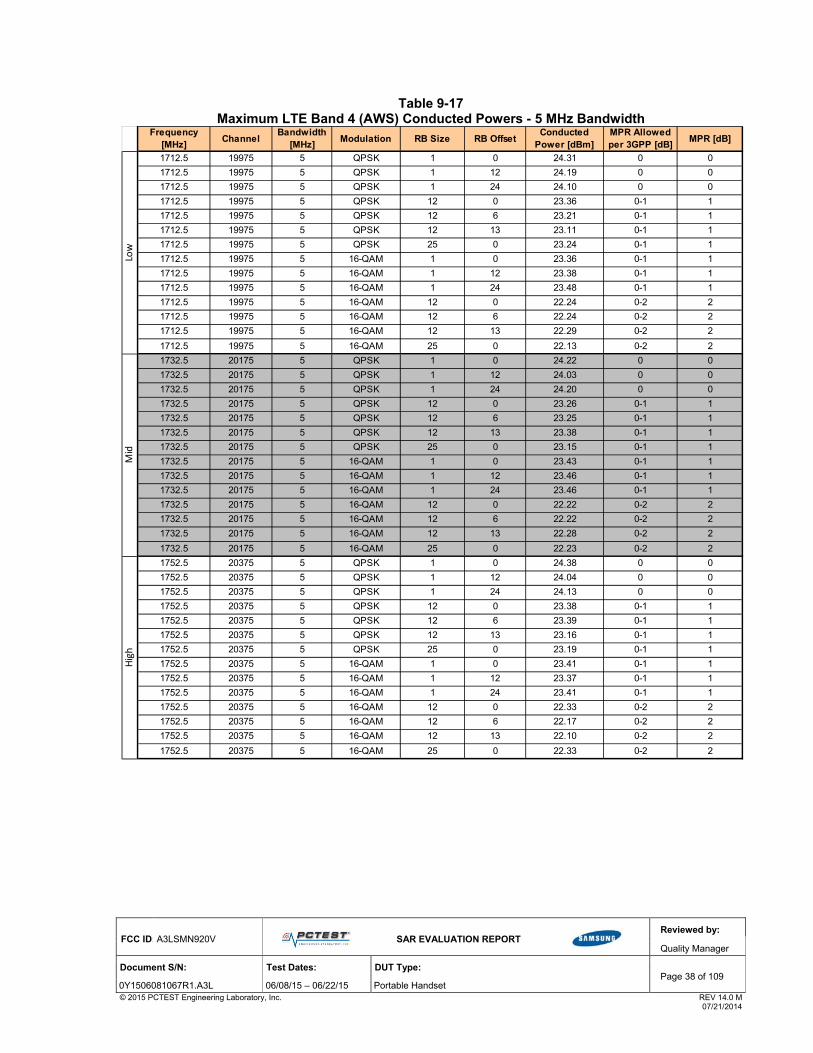
FCC ID: A3LSMN920V
SAR EVALUATION REPORT
Reviewed by:
Quality Manager
Document S/N: Test Dates: DUT Type: Page 38 of 109
0Y1506081067R1.A3L 06/08/15 – 06/22/15 Portable Handset © 2015 PCTEST Engineering Laboratory, Inc. REV 14.0 M 07/21/2014
Table 9-17 Maximum LTE Band 4 (AWS) Conducted Powers - 5 MHz Bandwidth
Frequency [MHz]
ChannelBandwidth
[MHz]Modulation RB Size RB Offset
Conducted Power [dBm]
MPR Allowed per 3GPP [dB]
MPR [dB]
1712.5 19975 5 QPSK 1 0 24.31 0 0
1712.5 19975 5 QPSK 1 12 24.19 0 0
1712.5 19975 5 QPSK 1 24 24.10 0 0
1712.5 19975 5 QPSK 12 0 23.36 0-1 1
1712.5 19975 5 QPSK 12 6 23.21 0-1 1
1712.5 19975 5 QPSK 12 13 23.11 0-1 1
1712.5 19975 5 QPSK 25 0 23.24 0-1 1
1712.5 19975 5 16-QAM 1 0 23.36 0-1 1
1712.5 19975 5 16-QAM 1 12 23.38 0-1 1
1712.5 19975 5 16-QAM 1 24 23.48 0-1 1
1712.5 19975 5 16-QAM 12 0 22.24 0-2 2
1712.5 19975 5 16-QAM 12 6 22.24 0-2 2
1712.5 19975 5 16-QAM 12 13 22.29 0-2 2
1712.5 19975 5 16-QAM 25 0 22.13 0-2 2
1732.5 20175 5 QPSK 1 0 24.22 0 0
1732.5 20175 5 QPSK 1 12 24.03 0 0
1732.5 20175 5 QPSK 1 24 24.20 0 0
1732.5 20175 5 QPSK 12 0 23.26 0-1 1
1732.5 20175 5 QPSK 12 6 23.25 0-1 1
1732.5 20175 5 QPSK 12 13 23.38 0-1 1
1732.5 20175 5 QPSK 25 0 23.15 0-1 1
1732.5 20175 5 16-QAM 1 0 23.43 0-1 1
1732.5 20175 5 16-QAM 1 12 23.46 0-1 1
1732.5 20175 5 16-QAM 1 24 23.46 0-1 1
1732.5 20175 5 16-QAM 12 0 22.22 0-2 2
1732.5 20175 5 16-QAM 12 6 22.22 0-2 2
1732.5 20175 5 16-QAM 12 13 22.28 0-2 2
1732.5 20175 5 16-QAM 25 0 22.23 0-2 2
1752.5 20375 5 QPSK 1 0 24.38 0 0
1752.5 20375 5 QPSK 1 12 24.04 0 0
1752.5 20375 5 QPSK 1 24 24.13 0 0
1752.5 20375 5 QPSK 12 0 23.38 0-1 1
1752.5 20375 5 QPSK 12 6 23.39 0-1 1
1752.5 20375 5 QPSK 12 13 23.16 0-1 1
1752.5 20375 5 QPSK 25 0 23.19 0-1 1
1752.5 20375 5 16-QAM 1 0 23.41 0-1 1
1752.5 20375 5 16-QAM 1 12 23.37 0-1 1
1752.5 20375 5 16-QAM 1 24 23.41 0-1 1
1752.5 20375 5 16-QAM 12 0 22.33 0-2 2
1752.5 20375 5 16-QAM 12 6 22.17 0-2 2
1752.5 20375 5 16-QAM 12 13 22.10 0-2 2
1752.5 20375 5 16-QAM 25 0 22.33 0-2 2
Low
Mid
High

FCC ID: A3LSMN920V
SAR EVALUATION REPORT
Reviewed by:
Quality Manager
Document S/N: Test Dates: DUT Type: Page 39 of 109
0Y1506081067R1.A3L 06/08/15 – 06/22/15 Portable Handset © 2015 PCTEST Engineering Laboratory, Inc. REV 14.0 M 07/21/2014
Table 9-18 Maximum LTE Band 4 (AWS) Conducted Powers - 3 MHz Bandwidth
Frequency [MHz]
ChannelBandwidth
[MHz]Modulation RB Size RB Offset
Conducted Power [dBm]
MPR Allowed per 3GPP [dB]
MPR [dB]
1711.5 19965 3 QPSK 1 0 24.32 0 0
1711.5 19965 3 QPSK 1 7 24.11 0 0
1711.5 19965 3 QPSK 1 14 24.23 0 0
1711.5 19965 3 QPSK 8 0 23.23 0-1 1
1711.5 19965 3 QPSK 8 4 23.33 0-1 1
1711.5 19965 3 QPSK 8 7 23.18 0-1 1
1711.5 19965 3 QPSK 15 0 23.22 0-1 1
1711.5 19965 3 16-QAM 1 0 23.38 0-1 1
1711.5 19965 3 16-QAM 1 7 23.44 0-1 1
1711.5 19965 3 16-QAM 1 14 23.48 0-1 1
1711.5 19965 3 16-QAM 8 0 22.25 0-2 2
1711.5 19965 3 16-QAM 8 4 22.23 0-2 2
1711.5 19965 3 16-QAM 8 7 22.38 0-2 2
1711.5 19965 3 16-QAM 15 0 22.07 0-2 2
1732.5 20175 3 QPSK 1 0 24.24 0 0
1732.5 20175 3 QPSK 1 7 24.17 0 0
1732.5 20175 3 QPSK 1 14 24.28 0 0
1732.5 20175 3 QPSK 8 0 23.27 0-1 1
1732.5 20175 3 QPSK 8 4 23.23 0-1 1
1732.5 20175 3 QPSK 8 7 23.37 0-1 1
1732.5 20175 3 QPSK 15 0 23.20 0-1 1
1732.5 20175 3 16-QAM 1 0 23.45 0-1 1
1732.5 20175 3 16-QAM 1 7 23.41 0-1 1
1732.5 20175 3 16-QAM 1 14 23.43 0-1 1
1732.5 20175 3 16-QAM 8 0 22.29 0-2 2
1732.5 20175 3 16-QAM 8 4 22.28 0-2 2
1732.5 20175 3 16-QAM 8 7 22.22 0-2 2
1732.5 20175 3 16-QAM 15 0 22.19 0-2 2
1753.5 20385 3 QPSK 1 0 24.33 0 0
1753.5 20385 3 QPSK 1 7 24.17 0 0
1753.5 20385 3 QPSK 1 14 24.13 0 0
1753.5 20385 3 QPSK 8 0 23.33 0-1 1
1753.5 20385 3 QPSK 8 4 23.22 0-1 1
1753.5 20385 3 QPSK 8 7 23.20 0-1 1
1753.5 20385 3 QPSK 15 0 23.26 0-1 1
1753.5 20385 3 16-QAM 1 0 23.44 0-1 1
1753.5 20385 3 16-QAM 1 7 23.44 0-1 1
1753.5 20385 3 16-QAM 1 14 23.40 0-1 1
1753.5 20385 3 16-QAM 8 0 22.23 0-2 2
1753.5 20385 3 16-QAM 8 4 22.16 0-2 2
1753.5 20385 3 16-QAM 8 7 22.19 0-2 2
1753.5 20385 3 16-QAM 15 0 22.34 0-2 2
Low
Mid
High

FCC ID: A3LSMN920V
SAR EVALUATION REPORT
Reviewed by:
Quality Manager
Document S/N: Test Dates: DUT Type: Page 40 of 109
0Y1506081067R1.A3L 06/08/15 – 06/22/15 Portable Handset © 2015 PCTEST Engineering Laboratory, Inc. REV 14.0 M 07/21/2014
Table 9-19 Maximum LTE Band 4 (AWS) Conducted Powers – 1.4 MHz Bandwidth
Frequency [MHz]
ChannelBandwidth
[MHz]Modulation RB Size RB Offset
Conducted Power [dBm]
MPR Allowed per 3GPP [dB]
MPR [dB]
1710.7 19957 1.4 QPSK 1 0 24.25 0 0
1710.7 19957 1.4 QPSK 1 2 24.13 0 0
1710.7 19957 1.4 QPSK 1 5 24.13 0 0
1710.7 19957 1.4 QPSK 3 0 24.25 0 0
1710.7 19957 1.4 QPSK 3 2 24.32 0 0
1710.7 19957 1.4 QPSK 3 3 24.14 0 0
1710.7 19957 1.4 QPSK 6 0 23.09 0-1 1
1710.7 19957 1.4 16-QAM 1 0 23.38 0-1 1
1710.7 19957 1.4 16-QAM 1 2 23.43 0-1 1
1710.7 19957 1.4 16-QAM 1 5 23.45 0-1 1
1710.7 19957 1.4 16-QAM 3 0 23.31 0-1 1
1710.7 19957 1.4 16-QAM 3 2 23.34 0-1 1
1710.7 19957 1.4 16-QAM 3 3 23.42 0-1 1
1710.7 19957 1.4 16-QAM 6 0 22.26 0-2 2
1732.5 20175 1.4 QPSK 1 0 24.20 0 0
1732.5 20175 1.4 QPSK 1 2 24.21 0 0
1732.5 20175 1.4 QPSK 1 5 24.09 0 0
1732.5 20175 1.4 QPSK 3 0 24.36 0 0
1732.5 20175 1.4 QPSK 3 2 24.28 0 0
1732.5 20175 1.4 QPSK 3 3 24.29 0 0
1732.5 20175 1.4 QPSK 6 0 23.27 0-1 1
1732.5 20175 1.4 16-QAM 1 0 23.44 0-1 1
1732.5 20175 1.4 16-QAM 1 2 23.45 0-1 1
1732.5 20175 1.4 16-QAM 1 5 23.35 0-1 1
1732.5 20175 1.4 16-QAM 3 0 23.23 0-1 1
1732.5 20175 1.4 16-QAM 3 2 23.18 0-1 1
1732.5 20175 1.4 16-QAM 3 3 23.28 0-1 1
1732.5 20175 1.4 16-QAM 6 0 22.15 0-2 2
1754.3 20393 1.4 QPSK 1 0 24.19 0 0
1754.3 20393 1.4 QPSK 1 2 24.14 0 0
1754.3 20393 1.4 QPSK 1 5 24.04 0 0
1754.3 20393 1.4 QPSK 3 0 24.37 0 0
1754.3 20393 1.4 QPSK 3 2 24.37 0 0
1754.3 20393 1.4 QPSK 3 3 24.16 0 0
1754.3 20393 1.4 QPSK 6 0 23.21 0-1 1
1754.3 20393 1.4 16-QAM 1 0 23.49 0-1 1
1754.3 20393 1.4 16-QAM 1 2 23.38 0-1 1
1754.3 20393 1.4 16-QAM 1 5 23.35 0-1 1
1754.3 20393 1.4 16-QAM 3 0 23.22 0-1 1
1754.3 20393 1.4 16-QAM 3 2 23.24 0-1 1
1754.3 20393 1.4 16-QAM 3 3 23.22 0-1 1
1754.3 20393 1.4 16-QAM 6 0 22.27 0-2 2
Low
Mid
High

FCC ID: A3LSMN920V
SAR EVALUATION REPORT
Reviewed by:
Quality Manager
Document S/N: Test Dates: DUT Type: Page 41 of 109
0Y1506081067R1.A3L 06/08/15 – 06/22/15 Portable Handset © 2015 PCTEST Engineering Laboratory, Inc. REV 14.0 M 07/21/2014
9.4.2 Maximum LTE Band 2 (PCS) Conducted Powers
Table 9-20
Maximum LTE Band 2 (PCS) Conducted Powers - 20 MHz Bandwidth
Frequency [MHz]
ChannelBandwidth
[MHz]Modulation RB Size RB Offset
Conducted Power [dBm]
MPR Allowed per 3GPP [dB]
MPR [dB]
1860 18700 20 QPSK 1 0 23.99 0 0
1860 18700 20 QPSK 1 50 23.97 0 0
1860 18700 20 QPSK 1 99 24.01 0 0
1860 18700 20 QPSK 50 0 23.02 0-1 1
1860 18700 20 QPSK 50 25 23.01 0-1 1
1860 18700 20 QPSK 50 50 22.97 0-1 1
1860 18700 20 QPSK 100 0 22.97 0-1 1
1860 18700 20 16QAM 1 0 23.35 0-1 1
1860 18700 20 16QAM 1 50 23.37 0-1 1
1860 18700 20 16QAM 1 99 23.23 0-1 1
1860 18700 20 16QAM 50 0 22.00 0-2 2
1860 18700 20 16QAM 50 25 21.91 0-2 2
1860 18700 20 16QAM 50 50 21.91 0-2 2
1860 18700 20 16QAM 100 0 21.94 0-2 2
1880.0 18900 20 QPSK 1 0 24.10 0 0
1880.0 18900 20 QPSK 1 50 23.85 0 0
1880.0 18900 20 QPSK 1 99 23.97 0 0
1880.0 18900 20 QPSK 50 0 23.13 0-1 1
1880.0 18900 20 QPSK 50 25 22.87 0-1 1
1880.0 18900 20 QPSK 50 50 22.89 0-1 1
1880.0 18900 20 QPSK 100 0 22.86 0-1 1
1880.0 18900 20 16QAM 1 0 23.44 0-1 1
1880.0 18900 20 16QAM 1 50 23.24 0-1 1
1880.0 18900 20 16QAM 1 99 23.38 0-1 1
1880.0 18900 20 16QAM 50 0 21.95 0-2 2
1880.0 18900 20 16QAM 50 25 21.87 0-2 2
1880.0 18900 20 16QAM 50 50 21.83 0-2 2
1880.0 18900 20 16QAM 100 0 21.83 0-2 2
1900 19100 20 QPSK 1 0 23.73 0 0
1900 19100 20 QPSK 1 50 23.74 0 0
1900 19100 20 QPSK 1 99 23.74 0 0
1900 19100 20 QPSK 50 0 23.01 0-1 1
1900 19100 20 QPSK 50 25 22.91 0-1 1
1900 19100 20 QPSK 50 50 22.92 0-1 1
1900 19100 20 QPSK 100 0 22.91 0-1 1
1900 19100 20 16QAM 1 0 23.39 0-1 1
1900 19100 20 16QAM 1 50 23.24 0-1 1
1900 19100 20 16QAM 1 99 23.13 0-1 1
1900 19100 20 16QAM 50 0 22.39 0-2 2
1900 19100 20 16QAM 50 25 21.92 0-2 2
1900 19100 20 16QAM 50 50 21.93 0-2 2
1900 19100 20 16QAM 100 0 21.94 0-2 2
High
Low
Mid

FCC ID: A3LSMN920V
SAR EVALUATION REPORT
Reviewed by:
Quality Manager
Document S/N: Test Dates: DUT Type: Page 42 of 109
0Y1506081067R1.A3L 06/08/15 – 06/22/15 Portable Handset © 2015 PCTEST Engineering Laboratory, Inc. REV 14.0 M 07/21/2014
Table 9-21 Maximum LTE Band 2 (PCS) Conducted Powers - 15 MHz Bandwidth
Frequency [MHz]
ChannelBandwidth
[MHz]Modulation RB Size RB Offset
Conducted Power [dBm]
MPR Allowed per 3GPP [dB]
MPR [dB]
1857.5 18675 15 QPSK 1 0 24.22 0 0
1857.5 18675 15 QPSK 1 36 24.12 0 0
1857.5 18675 15 QPSK 1 74 24.06 0 0
1857.5 18675 15 QPSK 36 0 23.22 0-1 1
1857.5 18675 15 QPSK 36 18 23.19 0-1 1
1857.5 18675 15 QPSK 36 37 23.15 0-1 1
1857.5 18675 15 QPSK 75 0 23.15 0-1 1
1857.5 18675 15 16QAM 1 0 23.43 0-1 1
1857.5 18675 15 16QAM 1 36 23.35 0-1 1
1857.5 18675 15 16QAM 1 74 23.29 0-1 1
1857.5 18675 15 16QAM 36 0 22.33 0-2 2
1857.5 18675 15 16QAM 36 18 22.32 0-2 2
1857.5 18675 15 16QAM 36 37 22.28 0-2 2
1857.5 18675 15 16QAM 75 0 22.13 0-2 2
1880.0 18900 15 QPSK 1 0 24.15 0 0
1880.0 18900 15 QPSK 1 36 23.96 0 0
1880.0 18900 15 QPSK 1 74 23.88 0 0
1880.0 18900 15 QPSK 36 0 23.07 0-1 1
1880.0 18900 15 QPSK 36 18 23.01 0-1 1
1880.0 18900 15 QPSK 36 37 22.98 0-1 1
1880.0 18900 15 QPSK 75 0 22.97 0-1 1
1880.0 18900 15 16QAM 1 0 23.42 0-1 1
1880.0 18900 15 16QAM 1 36 23.41 0-1 1
1880.0 18900 15 16QAM 1 74 23.38 0-1 1
1880.0 18900 15 16QAM 36 0 22.06 0-2 2
1880.0 18900 15 16QAM 36 18 22.01 0-2 2
1880.0 18900 15 16QAM 36 37 21.98 0-2 2
1880.0 18900 15 16QAM 75 0 22.01 0-2 2
1902.5 19125 15 QPSK 1 0 24.07 0 0
1902.5 19125 15 QPSK 1 36 24.11 0 0
1902.5 19125 15 QPSK 1 74 24.09 0 0
1902.5 19125 15 QPSK 36 0 23.16 0-1 1
1902.5 19125 15 QPSK 36 18 23.15 0-1 1
1902.5 19125 15 QPSK 36 37 23.02 0-1 1
1902.5 19125 15 QPSK 75 0 23.05 0-1 1
1902.5 19125 15 16QAM 1 0 23.28 0-1 1
1902.5 19125 15 16QAM 1 36 23.26 0-1 1
1902.5 19125 15 16QAM 1 74 23.24 0-1 1
1902.5 19125 15 16QAM 36 0 22.26 0-2 2
1902.5 19125 15 16QAM 36 18 22.21 0-2 2
1902.5 19125 15 16QAM 36 37 22.14 0-2 2
1902.5 19125 15 16QAM 75 0 22.06 0-2 2
Low
Mid
High

FCC ID: A3LSMN920V
SAR EVALUATION REPORT
Reviewed by:
Quality Manager
Document S/N: Test Dates: DUT Type: Page 43 of 109
0Y1506081067R1.A3L 06/08/15 – 06/22/15 Portable Handset © 2015 PCTEST Engineering Laboratory, Inc. REV 14.0 M 07/21/2014
Table 9-22 Maximum LTE Band 2 (PCS) Conducted Powers - 10 MHz Bandwidth
Frequency [MHz]
ChannelBandwidth
[MHz]Modulation RB Size RB Offset
Conducted Power [dBm]
MPR Allowed per 3GPP [dB]
MPR [dB]
1855 18650 10 QPSK 1 0 24.19 0 0
1855 18650 10 QPSK 1 25 24.08 0 0
1855 18650 10 QPSK 1 49 24.16 0 0
1855 18650 10 QPSK 25 0 23.23 0-1 1
1855 18650 10 QPSK 25 12 23.16 0-1 1
1855 18650 10 QPSK 25 25 23.18 0-1 1
1855 18650 10 QPSK 50 0 23.25 0-1 1
1855 18650 10 16QAM 1 0 23.42 0-1 1
1855 18650 10 16QAM 1 25 23.41 0-1 1
1855 18650 10 16QAM 1 49 23.48 0-1 1
1855 18650 10 16QAM 25 0 22.27 0-2 2
1855 18650 10 16QAM 25 12 22.14 0-2 2
1855 18650 10 16QAM 25 25 22.22 0-2 2
1855 18650 10 16QAM 50 0 22.28 0-2 2
1880.0 18900 10 QPSK 1 0 24.22 0 0
1880.0 18900 10 QPSK 1 25 24.09 0 0
1880.0 18900 10 QPSK 1 49 24.12 0 0
1880.0 18900 10 QPSK 25 0 23.00 0-1 1
1880.0 18900 10 QPSK 25 12 23.12 0-1 1
1880.0 18900 10 QPSK 25 25 23.07 0-1 1
1880.0 18900 10 QPSK 50 0 23.13 0-1 1
1880.0 18900 10 16QAM 1 0 23.49 0-1 1
1880.0 18900 10 16QAM 1 25 23.44 0-1 1
1880.0 18900 10 16QAM 1 49 23.49 0-1 1
1880.0 18900 10 16QAM 25 0 22.03 0-2 2
1880.0 18900 10 16QAM 25 12 22.13 0-2 2
1880.0 18900 10 16QAM 25 25 22.08 0-2 2
1880.0 18900 10 16QAM 50 0 22.16 0-2 2
1905 19150 10 QPSK 1 0 24.14 0 0
1905 19150 10 QPSK 1 25 24.06 0 0
1905 19150 10 QPSK 1 49 24.12 0 0
1905 19150 10 QPSK 25 0 23.21 0-1 1
1905 19150 10 QPSK 25 12 23.17 0-1 1
1905 19150 10 QPSK 25 25 23.20 0-1 1
1905 19150 10 QPSK 50 0 23.23 0-1 1
1905 19150 10 16QAM 1 0 23.50 0-1 1
1905 19150 10 16QAM 1 25 23.48 0-1 1
1905 19150 10 16QAM 1 49 23.46 0-1 1
1905 19150 10 16QAM 25 0 22.20 0-2 2
1905 19150 10 16QAM 25 12 22.21 0-2 2
1905 19150 10 16QAM 25 25 22.23 0-2 2
1905 19150 10 16QAM 50 0 22.22 0-2 2
Mid
High
Low

FCC ID: A3LSMN920V
SAR EVALUATION REPORT
Reviewed by:
Quality Manager
Document S/N: Test Dates: DUT Type: Page 44 of 109
0Y1506081067R1.A3L 06/08/15 – 06/22/15 Portable Handset © 2015 PCTEST Engineering Laboratory, Inc. REV 14.0 M 07/21/2014
Table 9-23 Maximum LTE Band 2 (PCS) Conducted Powers - 5 MHz Bandwidth
Frequency [MHz]
ChannelBandwidth
[MHz]Modulation RB Size RB Offset
Conducted Power [dBm]
MPR Allowed per 3GPP [dB]
MPR [dB]
1852.5 18625 5 QPSK 1 0 24.23 0 0
1852.5 18625 5 QPSK 1 12 24.15 0 0
1852.5 18625 5 QPSK 1 24 24.28 0 0
1852.5 18625 5 QPSK 12 0 23.33 0-1 1
1852.5 18625 5 QPSK 12 6 23.22 0-1 1
1852.5 18625 5 QPSK 12 13 23.08 0-1 1
1852.5 18625 5 QPSK 25 0 23.33 0-1 1
1852.5 18625 5 16-QAM 1 0 23.46 0-1 1
1852.5 18625 5 16-QAM 1 12 23.34 0-1 1
1852.5 18625 5 16-QAM 1 24 23.46 0-1 1
1852.5 18625 5 16-QAM 12 0 22.21 0-2 2
1852.5 18625 5 16-QAM 12 6 22.19 0-2 2
1852.5 18625 5 16-QAM 12 13 22.24 0-2 2
1852.5 18625 5 16-QAM 25 0 22.27 0-2 2
1880.0 18900 5 QPSK 1 0 24.15 0 0
1880.0 18900 5 QPSK 1 12 23.99 0 0
1880.0 18900 5 QPSK 1 24 24.22 0 0
1880.0 18900 5 QPSK 12 0 23.10 0-1 1
1880.0 18900 5 QPSK 12 6 23.13 0-1 1
1880.0 18900 5 QPSK 12 13 23.11 0-1 1
1880.0 18900 5 QPSK 25 0 23.18 0-1 1
1880.0 18900 5 16-QAM 1 0 23.40 0-1 1
1880.0 18900 5 16-QAM 1 12 23.43 0-1 1
1880.0 18900 5 16-QAM 1 24 23.44 0-1 1
1880.0 18900 5 16-QAM 12 0 22.05 0-2 2
1880.0 18900 5 16-QAM 12 6 22.09 0-2 2
1880.0 18900 5 16-QAM 12 13 22.08 0-2 2
1880.0 18900 5 16-QAM 25 0 22.12 0-2 2
1907.5 19175 5 QPSK 1 0 24.20 0 0
1907.5 19175 5 QPSK 1 12 24.12 0 0
1907.5 19175 5 QPSK 1 24 24.18 0 0
1907.5 19175 5 QPSK 12 0 23.19 0-1 1
1907.5 19175 5 QPSK 12 6 23.19 0-1 1
1907.5 19175 5 QPSK 12 13 23.24 0-1 1
1907.5 19175 5 QPSK 25 0 23.33 0-1 1
1907.5 19175 5 16-QAM 1 0 23.50 0-1 1
1907.5 19175 5 16-QAM 1 12 23.49 0-1 1
1907.5 19175 5 16-QAM 1 24 23.50 0-1 1
1907.5 19175 5 16-QAM 12 0 22.24 0-2 2
1907.5 19175 5 16-QAM 12 6 22.11 0-2 2
1907.5 19175 5 16-QAM 12 13 22.14 0-2 2
1907.5 19175 5 16-QAM 25 0 22.17 0-2 2
High
Mid
Low

FCC ID: A3LSMN920V
SAR EVALUATION REPORT
Reviewed by:
Quality Manager
Document S/N: Test Dates: DUT Type: Page 45 of 109
0Y1506081067R1.A3L 06/08/15 – 06/22/15 Portable Handset © 2015 PCTEST Engineering Laboratory, Inc. REV 14.0 M 07/21/2014
Table 9-24 Maximum LTE Band 2 (PCS) Conducted Powers - 3 MHz Bandwidth
Frequency [MHz]
ChannelBandwidth
[MHz]Modulation RB Size RB Offset
Conducted Power [dBm]
MPR Allowed per 3GPP [dB]
MPR [dB]
1851.5 18615 3 QPSK 1 0 24.11 0 0
1851.5 18615 3 QPSK 1 7 23.98 0 0
1851.5 18615 3 QPSK 1 14 24.14 0 0
1851.5 18615 3 QPSK 8 0 23.31 0-1 1
1851.5 18615 3 QPSK 8 4 23.06 0-1 1
1851.5 18615 3 QPSK 8 7 23.12 0-1 1
1851.5 18615 3 QPSK 15 0 23.26 0-1 1
1851.5 18615 3 16-QAM 1 0 23.35 0-1 1
1851.5 18615 3 16-QAM 1 7 23.44 0-1 1
1851.5 18615 3 16-QAM 1 14 23.44 0-1 1
1851.5 18615 3 16-QAM 8 0 22.35 0-2 2
1851.5 18615 3 16-QAM 8 4 22.18 0-2 2
1851.5 18615 3 16-QAM 8 7 22.19 0-2 2
1851.5 18615 3 16-QAM 15 0 22.22 0-2 2
1880.0 18900 3 QPSK 1 0 24.23 0 0
1880.0 18900 3 QPSK 1 7 24.03 0 0
1880.0 18900 3 QPSK 1 14 24.19 0 0
1880.0 18900 3 QPSK 8 0 23.09 0-1 1
1880.0 18900 3 QPSK 8 4 23.08 0-1 1
1880.0 18900 3 QPSK 8 7 23.11 0-1 1
1880.0 18900 3 QPSK 15 0 23.23 0-1 1
1880.0 18900 3 16-QAM 1 0 23.42 0-1 1
1880.0 18900 3 16-QAM 1 7 23.38 0-1 1
1880.0 18900 3 16-QAM 1 14 23.41 0-1 1
1880.0 18900 3 16-QAM 8 0 22.12 0-2 2
1880.0 18900 3 16-QAM 8 4 22.06 0-2 2
1880.0 18900 3 16-QAM 8 7 21.99 0-2 2
1880.0 18900 3 16-QAM 15 0 22.22 0-2 2
1908.5 19185 3 QPSK 1 0 24.22 0 0
1908.5 19185 3 QPSK 1 7 24.16 0 0
1908.5 19185 3 QPSK 1 14 24.02 0 0
1908.5 19185 3 QPSK 8 0 23.24 0-1 1
1908.5 19185 3 QPSK 8 4 23.08 0-1 1
1908.5 19185 3 QPSK 8 7 23.10 0-1 1
1908.5 19185 3 QPSK 15 0 23.19 0-1 1
1908.5 19185 3 16-QAM 1 0 23.48 0-1 1
1908.5 19185 3 16-QAM 1 7 23.45 0-1 1
1908.5 19185 3 16-QAM 1 14 23.40 0-1 1
1908.5 19185 3 16-QAM 8 0 22.23 0-2 2
1908.5 19185 3 16-QAM 8 4 22.31 0-2 2
1908.5 19185 3 16-QAM 8 7 22.13 0-2 2
1908.5 19185 3 16-QAM 15 0 22.13 0-2 2
Low
High
Mid

FCC ID: A3LSMN920V
SAR EVALUATION REPORT
Reviewed by:
Quality Manager
Document S/N: Test Dates: DUT Type: Page 46 of 109
0Y1506081067R1.A3L 06/08/15 – 06/22/15 Portable Handset © 2015 PCTEST Engineering Laboratory, Inc. REV 14.0 M 07/21/2014
Table 9-25 Maximum LTE Band 2 (PCS) Conducted Powers – 1.4 MHz Bandwidth
Frequency [MHz]
ChannelBandwidth
[MHz]Modulation RB Size RB Offset
Conducted Power [dBm]
MPR Allowed per 3GPP [dB]
MPR [dB]
1850.7 18607 1.4 QPSK 1 0 24.12 0 0
1850.7 18607 1.4 QPSK 1 2 24.00 0 0
1850.7 18607 1.4 QPSK 1 5 24.12 0 0
1850.7 18607 1.4 QPSK 3 0 24.25 0 0
1850.7 18607 1.4 QPSK 3 2 24.22 0 0
1850.7 18607 1.4 QPSK 3 3 24.11 0 0
1850.7 18607 1.4 QPSK 6 0 23.18 0-1 1
1850.7 18607 1.4 16-QAM 1 0 23.37 0-1 1
1850.7 18607 1.4 16-QAM 1 2 23.37 0-1 1
1850.7 18607 1.4 16-QAM 1 5 23.50 0-1 1
1850.7 18607 1.4 16-QAM 3 0 23.24 0-1 1
1850.7 18607 1.4 16-QAM 3 2 23.04 0-1 1
1850.7 18607 1.4 16-QAM 3 3 23.24 0-1 1
1850.7 18607 1.4 16-QAM 6 0 22.34 0-2 2
1880.0 18900 1.4 QPSK 1 0 24.19 0 0
1880.0 18900 1.4 QPSK 1 2 24.01 0 0
1880.0 18900 1.4 QPSK 1 5 24.15 0 0
1880.0 18900 1.4 QPSK 3 0 23.96 0 0
1880.0 18900 1.4 QPSK 3 2 24.18 0 0
1880.0 18900 1.4 QPSK 3 3 24.13 0 0
1880.0 18900 1.4 QPSK 6 0 23.12 0-1 1
1880.0 18900 1.4 16-QAM 1 0 23.49 0-1 1
1880.0 18900 1.4 16-QAM 1 2 23.45 0-1 1
1880.0 18900 1.4 16-QAM 1 5 23.48 0-1 1
1880.0 18900 1.4 16-QAM 3 0 23.04 0-1 1
1880.0 18900 1.4 16-QAM 3 2 23.20 0-1 1
1880.0 18900 1.4 16-QAM 3 3 23.13 0-1 1
1880.0 18900 1.4 16-QAM 6 0 22.16 0-2 2
1909.3 19193 1.4 QPSK 1 0 24.20 0 0
1909.3 19193 1.4 QPSK 1 2 24.06 0 0
1909.3 19193 1.4 QPSK 1 5 24.15 0 0
1909.3 19193 1.4 QPSK 3 0 24.27 0 0
1909.3 19193 1.4 QPSK 3 2 24.11 0 0
1909.3 19193 1.4 QPSK 3 3 24.26 0 0
1909.3 19193 1.4 QPSK 6 0 23.15 0-1 1
1909.3 19193 1.4 16-QAM 1 0 23.50 0-1 1
1909.3 19193 1.4 16-QAM 1 2 23.38 0-1 1
1909.3 19193 1.4 16-QAM 1 5 23.49 0-1 1
1909.3 19193 1.4 16-QAM 3 0 23.20 0-1 1
1909.3 19193 1.4 16-QAM 3 2 23.23 0-1 1
1909.3 19193 1.4 16-QAM 3 3 23.20 0-1 1
1909.3 19193 1.4 16-QAM 6 0 22.14 0-2 2
Low
Mid
High

FCC ID: A3LSMN920V
SAR EVALUATION REPORT
Reviewed by:
Quality Manager
Document S/N: Test Dates: DUT Type: Page 47 of 109
0Y1506081067R1.A3L 06/08/15 – 06/22/15 Portable Handset © 2015 PCTEST Engineering Laboratory, Inc. REV 14.0 M 07/21/2014
9.5 Reduced Conducted Powers
9.5.1 Reduced LTE Band 4 (AWS) Conducted Powers – Hotspot, Hand
Table 9-26
Reduced LTE Band 4 (AWS) Conducted Powers - 20 MHz Bandwidth –Hotspot, Hand
Note: LTE Band 4 (AWS) at 20 MHz bandwidth does not support three non-overlapping channels. Per
KDB Publication 941225 D05v02, when a device supports overlapping channel assignment in a channel bandwidth configuration, the middle channel of the group of overlapping channels should be selected for
testing.
Frequency [MHz]
ChannelBandwidth
[MHz]Modulation RB Size RB Offset
Conducted Power [dBm]
MPR Allowed per 3GPP [dB]
MPR [dB]
1732.5 20175 20 QPSK 1 0 22.14 0 0
1732.5 20175 20 QPSK 1 50 21.99 0 0
1732.5 20175 20 QPSK 1 99 21.86 0 0
1732.5 20175 20 QPSK 50 0 21.85 0-1 0
1732.5 20175 20 QPSK 50 25 21.90 0-1 0
1732.5 20175 20 QPSK 50 50 21.71 0-1 0
1732.5 20175 20 QPSK 100 0 21.89 0-1 0
1732.5 20175 20 16QAM 1 0 22.29 0-1 0
1732.5 20175 20 16QAM 1 50 22.28 0-1 0
1732.5 20175 20 16QAM 1 99 22.22 0-1 0
1732.5 20175 20 16QAM 50 0 21.91 0-2 0
1732.5 20175 20 16QAM 50 25 21.88 0-2 0
1732.5 20175 20 16QAM 50 50 21.82 0-2 0
1732.5 20175 20 16QAM 100 0 22.02 0-2 0
Mid
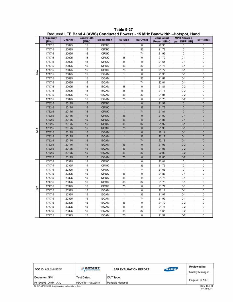
FCC ID: A3LSMN920V
SAR EVALUATION REPORT
Reviewed by:
Quality Manager
Document S/N: Test Dates: DUT Type: Page 48 of 109
0Y1506081067R1.A3L 06/08/15 – 06/22/15 Portable Handset © 2015 PCTEST Engineering Laboratory, Inc. REV 14.0 M 07/21/2014
Table 9-27 Reduced LTE Band 4 (AWS) Conducted Powers - 15 MHz Bandwidth –Hotspot, Hand
Frequency [MHz]
ChannelBandwidth
[MHz]Modulation RB Size RB Offset
Conducted Power [dBm]
MPR Allowed per 3GPP [dB]
MPR [dB]
1717.5 20025 15 QPSK 1 0 22.30 0 0
1717.5 20025 15 QPSK 1 36 21.72 0 0
1717.5 20025 15 QPSK 1 74 21.99 0 0
1717.5 20025 15 QPSK 36 0 21.72 0-1 0
1717.5 20025 15 QPSK 36 18 21.65 0-1 0
1717.5 20025 15 QPSK 36 37 21.75 0-1 0
1717.5 20025 15 QPSK 75 0 21.72 0-1 0
1717.5 20025 15 16QAM 1 0 21.96 0-1 0
1717.5 20025 15 16QAM 1 36 21.81 0-1 0
1717.5 20025 15 16QAM 1 74 22.04 0-1 0
1717.5 20025 15 16QAM 36 0 21.81 0-2 0
1717.5 20025 15 16QAM 36 18 21.77 0-2 0
1717.5 20025 15 16QAM 36 37 21.81 0-2 0
1717.5 20025 15 16QAM 75 0 21.73 0-2 0
1732.5 20175 15 QPSK 1 0 21.99 0 0
1732.5 20175 15 QPSK 1 36 21.79 0 0
1732.5 20175 15 QPSK 1 74 21.81 0 0
1732.5 20175 15 QPSK 36 0 21.90 0-1 0
1732.5 20175 15 QPSK 36 18 21.87 0-1 0
1732.5 20175 15 QPSK 36 37 21.92 0-1 0
1732.5 20175 15 QPSK 75 0 21.90 0-1 0
1732.5 20175 15 16QAM 1 0 22.14 0-1 0
1732.5 20175 15 16QAM 1 36 22.17 0-1 0
1732.5 20175 15 16QAM 1 74 22.18 0-1 0
1732.5 20175 15 16QAM 36 0 21.93 0-2 0
1732.5 20175 15 16QAM 36 18 21.98 0-2 0
1732.5 20175 15 16QAM 36 37 22.03 0-2 0
1732.5 20175 15 16QAM 75 0 22.00 0-2 0
1747.5 20325 15 QPSK 1 0 22.01 0 0
1747.5 20325 15 QPSK 1 36 21.76 0 0
1747.5 20325 15 QPSK 1 74 21.65 0 0
1747.5 20325 15 QPSK 36 0 21.83 0-1 0
1747.5 20325 15 QPSK 36 18 21.78 0-1 0
1747.5 20325 15 QPSK 36 37 21.73 0-1 0
1747.5 20325 15 QPSK 75 0 21.77 0-1 0
1747.5 20325 15 16QAM 1 0 22.11 0-1 0
1747.5 20325 15 16QAM 1 36 21.87 0-1 0
1747.5 20325 15 16QAM 1 74 21.92 0-1 0
1747.5 20325 15 16QAM 36 0 21.79 0-2 0
1747.5 20325 15 16QAM 36 18 21.75 0-2 0
1747.5 20325 15 16QAM 36 37 21.65 0-2 0
1747.5 20325 15 16QAM 75 0 21.92 0-2 0
High
Low
Mid
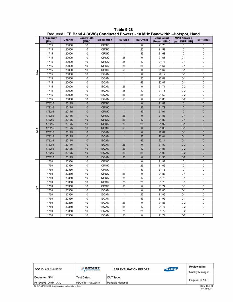
FCC ID: A3LSMN920V
SAR EVALUATION REPORT
Reviewed by:
Quality Manager
Document S/N: Test Dates: DUT Type: Page 49 of 109
0Y1506081067R1.A3L 06/08/15 – 06/22/15 Portable Handset © 2015 PCTEST Engineering Laboratory, Inc. REV 14.0 M 07/21/2014
Table 9-28 Reduced LTE Band 4 (AWS) Conducted Powers - 10 MHz Bandwidth –Hotspot, Hand
Frequency [MHz]
ChannelBandwidth
[MHz]Modulation RB Size RB Offset
Conducted Power [dBm]
MPR Allowed per 3GPP [dB]
MPR [dB]
1715 20000 10 QPSK 1 0 21.73 0 0
1715 20000 10 QPSK 1 25 21.59 0 0
1715 20000 10 QPSK 1 49 21.68 0 0
1715 20000 10 QPSK 25 0 21.66 0-1 0
1715 20000 10 QPSK 25 12 21.73 0-1 0
1715 20000 10 QPSK 25 25 21.67 0-1 0
1715 20000 10 QPSK 50 0 21.67 0-1 0
1715 20000 10 16QAM 1 0 22.12 0-1 0
1715 20000 10 16QAM 1 25 22.02 0-1 0
1715 20000 10 16QAM 1 49 22.07 0-1 0
1715 20000 10 16QAM 25 0 21.71 0-2 0
1715 20000 10 16QAM 25 12 21.76 0-2 0
1715 20000 10 16QAM 25 25 21.69 0-2 0
1715 20000 10 16QAM 50 0 21.66 0-2 0
1732.5 20175 10 QPSK 1 0 21.82 0 0
1732.5 20175 10 QPSK 1 25 21.78 0 0
1732.5 20175 10 QPSK 1 49 21.91 0 0
1732.5 20175 10 QPSK 25 0 21.86 0-1 0
1732.5 20175 10 QPSK 25 12 21.83 0-1 0
1732.5 20175 10 QPSK 25 25 21.92 0-1 0
1732.5 20175 10 QPSK 50 0 21.88 0-1 0
1732.5 20175 10 16QAM 1 0 22.07 0-1 0
1732.5 20175 10 16QAM 1 25 22.04 0-1 0
1732.5 20175 10 16QAM 1 49 22.14 0-1 0
1732.5 20175 10 16QAM 25 0 21.82 0-2 0
1732.5 20175 10 16QAM 25 12 21.87 0-2 0
1732.5 20175 10 16QAM 25 25 21.96 0-2 0
1732.5 20175 10 16QAM 50 0 21.93 0-2 0
1750 20350 10 QPSK 1 0 21.99 0 0
1750 20350 10 QPSK 1 25 21.63 0 0
1750 20350 10 QPSK 1 49 21.78 0 0
1750 20350 10 QPSK 25 0 21.83 0-1 0
1750 20350 10 QPSK 25 12 21.78 0-1 0
1750 20350 10 QPSK 25 25 21.70 0-1 0
1750 20350 10 QPSK 50 0 21.74 0-1 0
1750 20350 10 16QAM 1 0 22.05 0-1 0
1750 20350 10 16QAM 1 25 21.85 0-1 0
1750 20350 10 16QAM 1 49 21.99 0-1 0
1750 20350 10 16QAM 25 0 21.86 0-2 0
1750 20350 10 16QAM 25 12 21.77 0-2 0
1750 20350 10 16QAM 25 25 21.72 0-2 0
1750 20350 10 16QAM 50 0 21.74 0-2 0
Low
Mid
High

FCC ID: A3LSMN920V
SAR EVALUATION REPORT
Reviewed by:
Quality Manager
Document S/N: Test Dates: DUT Type: Page 50 of 109
0Y1506081067R1.A3L 06/08/15 – 06/22/15 Portable Handset © 2015 PCTEST Engineering Laboratory, Inc. REV 14.0 M 07/21/2014
Table 9-29 Reduced LTE Band 4 (AWS) Conducted Powers - 5 MHz Bandwidth –Hotspot, Hand
Frequency [MHz]
ChannelBandwidth
[MHz]Modulation RB Size RB Offset
Conducted Power [dBm]
MPR Allowed per 3GPP [dB]
MPR [dB]
1712.5 19975 5 QPSK 1 0 21.60 0 0
1712.5 19975 5 QPSK 1 12 21.60 0 0
1712.5 19975 5 QPSK 1 24 21.72 0 0
1712.5 19975 5 QPSK 12 0 21.69 0-1 0
1712.5 19975 5 QPSK 12 6 21.68 0-1 0
1712.5 19975 5 QPSK 12 13 21.66 0-1 0
1712.5 19975 5 QPSK 25 0 21.65 0-1 0
1712.5 19975 5 16-QAM 1 0 22.07 0-1 0
1712.5 19975 5 16-QAM 1 12 21.93 0-1 0
1712.5 19975 5 16-QAM 1 24 22.05 0-1 0
1712.5 19975 5 16-QAM 12 0 21.74 0-2 0
1712.5 19975 5 16-QAM 12 6 21.73 0-2 0
1712.5 19975 5 16-QAM 12 13 21.66 0-2 0
1712.5 19975 5 16-QAM 25 0 21.69 0-2 0
1732.5 20175 5 QPSK 1 0 21.82 0 0
1732.5 20175 5 QPSK 1 12 21.95 0 0
1732.5 20175 5 QPSK 1 24 21.93 0 0
1732.5 20175 5 QPSK 12 0 21.86 0-1 0
1732.5 20175 5 QPSK 12 6 21.86 0-1 0
1732.5 20175 5 QPSK 12 13 21.87 0-1 0
1732.5 20175 5 QPSK 25 0 21.92 0-1 0
1732.5 20175 5 16-QAM 1 0 22.17 0-1 0
1732.5 20175 5 16-QAM 1 12 22.21 0-1 0
1732.5 20175 5 16-QAM 1 24 22.23 0-1 0
1732.5 20175 5 16-QAM 12 0 21.88 0-2 0
1732.5 20175 5 16-QAM 12 6 21.94 0-2 0
1732.5 20175 5 16-QAM 12 13 21.91 0-2 0
1732.5 20175 5 16-QAM 25 0 21.93 0-2 0
1752.5 20375 5 QPSK 1 0 22.03 0 0
1752.5 20375 5 QPSK 1 12 21.80 0 0
1752.5 20375 5 QPSK 1 24 21.69 0 0
1752.5 20375 5 QPSK 12 0 21.73 0-1 0
1752.5 20375 5 QPSK 12 6 21.72 0-1 0
1752.5 20375 5 QPSK 12 13 21.65 0-1 0
1752.5 20375 5 QPSK 25 0 21.67 0-1 0
1752.5 20375 5 16-QAM 1 0 22.10 0-1 0
1752.5 20375 5 16-QAM 1 12 22.07 0-1 0
1752.5 20375 5 16-QAM 1 24 22.01 0-1 0
1752.5 20375 5 16-QAM 12 0 21.77 0-2 0
1752.5 20375 5 16-QAM 12 6 21.75 0-2 0
1752.5 20375 5 16-QAM 12 13 21.68 0-2 0
1752.5 20375 5 16-QAM 25 0 21.76 0-2 0
Low
Mid
High

FCC ID: A3LSMN920V
SAR EVALUATION REPORT
Reviewed by:
Quality Manager
Document S/N: Test Dates: DUT Type: Page 51 of 109
0Y1506081067R1.A3L 06/08/15 – 06/22/15 Portable Handset © 2015 PCTEST Engineering Laboratory, Inc. REV 14.0 M 07/21/2014
Table 9-30 Reduced LTE Band 4 (AWS) Conducted Powers - 3 MHz Bandwidth –Hotspot, Hand
Frequency [MHz]
ChannelBandwidth
[MHz]Modulation RB Size RB Offset
Conducted Power [dBm]
MPR Allowed per 3GPP [dB]
MPR [dB]
1711.5 19965 3 QPSK 1 0 21.59 0 0
1711.5 19965 3 QPSK 1 7 21.69 0 0
1711.5 19965 3 QPSK 1 14 21.54 0 0
1711.5 19965 3 QPSK 8 0 21.67 0-1 0
1711.5 19965 3 QPSK 8 4 21.66 0-1 0
1711.5 19965 3 QPSK 8 7 21.63 0-1 0
1711.5 19965 3 QPSK 15 0 21.60 0-1 0
1711.5 19965 3 16-QAM 1 0 22.08 0-1 0
1711.5 19965 3 16-QAM 1 7 22.16 0-1 0
1711.5 19965 3 16-QAM 1 14 21.98 0-1 0
1711.5 19965 3 16-QAM 8 0 21.59 0-2 0
1711.5 19965 3 16-QAM 8 4 21.65 0-2 0
1711.5 19965 3 16-QAM 8 7 21.59 0-2 0
1711.5 19965 3 16-QAM 15 0 21.72 0-2 0
1732.5 20175 3 QPSK 1 0 21.70 0 0
1732.5 20175 3 QPSK 1 7 21.98 0 0
1732.5 20175 3 QPSK 1 14 21.92 0 0
1732.5 20175 3 QPSK 8 0 21.75 0-1 0
1732.5 20175 3 QPSK 8 4 21.89 0-1 0
1732.5 20175 3 QPSK 8 7 21.86 0-1 0
1732.5 20175 3 QPSK 15 0 21.88 0-1 0
1732.5 20175 3 16-QAM 1 0 22.10 0-1 0
1732.5 20175 3 16-QAM 1 7 22.06 0-1 0
1732.5 20175 3 16-QAM 1 14 21.99 0-1 0
1732.5 20175 3 16-QAM 8 0 21.60 0-2 0
1732.5 20175 3 16-QAM 8 4 21.72 0-2 0
1732.5 20175 3 16-QAM 8 7 21.79 0-2 0
1732.5 20175 3 16-QAM 15 0 21.87 0-2 0
1753.5 20385 3 QPSK 1 0 21.62 0 0
1753.5 20385 3 QPSK 1 7 21.81 0 0
1753.5 20385 3 QPSK 1 14 21.59 0 0
1753.5 20385 3 QPSK 8 0 21.61 0-1 0
1753.5 20385 3 QPSK 8 4 21.71 0-1 0
1753.5 20385 3 QPSK 8 7 21.66 0-1 0
1753.5 20385 3 QPSK 15 0 21.62 0-1 0
1753.5 20385 3 16-QAM 1 0 21.78 0-1 0
1753.5 20385 3 16-QAM 1 7 21.84 0-1 0
1753.5 20385 3 16-QAM 1 14 21.76 0-1 0
1753.5 20385 3 16-QAM 8 0 21.72 0-2 0
1753.5 20385 3 16-QAM 8 4 21.69 0-2 0
1753.5 20385 3 16-QAM 8 7 21.71 0-2 0
1753.5 20385 3 16-QAM 15 0 21.59 0-2 0
Low
Mid
High

FCC ID: A3LSMN920V
SAR EVALUATION REPORT
Reviewed by:
Quality Manager
Document S/N: Test Dates: DUT Type: Page 52 of 109
0Y1506081067R1.A3L 06/08/15 – 06/22/15 Portable Handset © 2015 PCTEST Engineering Laboratory, Inc. REV 14.0 M 07/21/2014
Table 9-31 Reduced LTE Band 4 (AWS) Conducted Powers – 1.4 MHz Bandwidth –Hotspot, Hand
Frequency [MHz]
ChannelBandwidth
[MHz]Modulation RB Size RB Offset
Conducted Power [dBm]
MPR Allowed per 3GPP [dB]
MPR [dB]
1710.7 19957 1.4 QPSK 1 0 21.73 0 0
1710.7 19957 1.4 QPSK 1 2 21.65 0 0
1710.7 19957 1.4 QPSK 1 5 21.73 0 0
1710.7 19957 1.4 QPSK 3 0 21.68 0 0
1710.7 19957 1.4 QPSK 3 2 21.68 0 0
1710.7 19957 1.4 QPSK 3 3 21.67 0 0
1710.7 19957 1.4 QPSK 6 0 21.66 0-1 0
1710.7 19957 1.4 16-QAM 1 0 22.05 0-1 0
1710.7 19957 1.4 16-QAM 1 2 21.98 0-1 0
1710.7 19957 1.4 16-QAM 1 5 22.03 0-1 0
1710.7 19957 1.4 16-QAM 3 0 21.71 0-1 0
1710.7 19957 1.4 16-QAM 3 2 21.72 0-1 0
1710.7 19957 1.4 16-QAM 3 3 21.68 0-1 0
1710.7 19957 1.4 16-QAM 6 0 21.70 0-2 0
1732.5 20175 1.4 QPSK 1 0 21.83 0 0
1732.5 20175 1.4 QPSK 1 2 21.87 0 0
1732.5 20175 1.4 QPSK 1 5 21.89 0 0
1732.5 20175 1.4 QPSK 3 0 21.84 0 0
1732.5 20175 1.4 QPSK 3 2 21.86 0 0
1732.5 20175 1.4 QPSK 3 3 21.89 0 0
1732.5 20175 1.4 QPSK 6 0 21.89 0-1 0
1732.5 20175 1.4 16-QAM 1 0 22.12 0-1 0
1732.5 20175 1.4 16-QAM 1 2 22.12 0-1 0
1732.5 20175 1.4 16-QAM 1 5 22.13 0-1 0
1732.5 20175 1.4 16-QAM 3 0 21.80 0-1 0
1732.5 20175 1.4 16-QAM 3 2 21.87 0-1 0
1732.5 20175 1.4 16-QAM 3 3 21.92 0-1 0
1732.5 20175 1.4 16-QAM 6 0 21.93 0-2 0
1754.3 20393 1.4 QPSK 1 0 21.91 0 0
1754.3 20393 1.4 QPSK 1 2 21.75 0 0
1754.3 20393 1.4 QPSK 1 5 21.67 0 0
1754.3 20393 1.4 QPSK 3 0 21.75 0 0
1754.3 20393 1.4 QPSK 3 2 21.74 0 0
1754.3 20393 1.4 QPSK 3 3 21.68 0 0
1754.3 20393 1.4 QPSK 6 0 21.70 0-1 0
1754.3 20393 1.4 16-QAM 1 0 22.01 0-1 0
1754.3 20393 1.4 16-QAM 1 2 21.90 0-1 0
1754.3 20393 1.4 16-QAM 1 5 21.92 0-1 0
1754.3 20393 1.4 16-QAM 3 0 21.78 0-1 0
1754.3 20393 1.4 16-QAM 3 2 21.74 0-1 0
1754.3 20393 1.4 16-QAM 3 3 21.69 0-1 0
1754.3 20393 1.4 16-QAM 6 0 21.75 0-2 0
High
Low
Mid

FCC ID: A3LSMN920V
SAR EVALUATION REPORT
Reviewed by:
Quality Manager
Document S/N: Test Dates: DUT Type: Page 53 of 109
0Y1506081067R1.A3L 06/08/15 – 06/22/15 Portable Handset © 2015 PCTEST Engineering Laboratory, Inc. REV 14.0 M 07/21/2014
9.5.2 Reduced LTE Band 2 (PCS) Conducted Powers - Hand
Table 9-32
Reduced LTE Band 2 (PCS) Conducted Powers - 20 MHz Bandwidth - Hand
Frequency [MHz]
ChannelBandwidth
[MHz]Modulation RB Size RB Offset
Conducted Power [dBm]
MPR Allowed per 3GPP [dB]
MPR [dB]
1860 18700 20 QPSK 1 0 22.02 0 0
1860 18700 20 QPSK 1 50 21.91 0 0
1860 18700 20 QPSK 1 99 21.81 0 0
1860 18700 20 QPSK 50 0 21.86 0-1 0
1860 18700 20 QPSK 50 25 21.88 0-1 0
1860 18700 20 QPSK 50 50 21.80 0-1 0
1860 18700 20 QPSK 100 0 21.77 0-1 0
1860 18700 20 16QAM 1 0 22.12 0-1 0
1860 18700 20 16QAM 1 50 22.18 0-1 0
1860 18700 20 16QAM 1 99 22.09 0-1 0
1860 18700 20 16QAM 50 0 21.94 0-2 0
1860 18700 20 16QAM 50 25 21.80 0-2 0
1860 18700 20 16QAM 50 50 21.75 0-2 0
1860 18700 20 16QAM 100 0 21.76 0-2 0
1880.0 18900 20 QPSK 1 0 21.98 0 0
1880.0 18900 20 QPSK 1 50 21.86 0 0
1880.0 18900 20 QPSK 1 99 21.72 0 0
1880.0 18900 20 QPSK 50 0 21.69 0-1 0
1880.0 18900 20 QPSK 50 25 21.72 0-1 0
1880.0 18900 20 QPSK 50 50 21.75 0-1 0
1880.0 18900 20 QPSK 100 0 21.76 0-1 0
1880.0 18900 20 16QAM 1 0 22.23 0-1 0
1880.0 18900 20 16QAM 1 50 22.06 0-1 0
1880.0 18900 20 16QAM 1 99 22.17 0-1 0
1880.0 18900 20 16QAM 50 0 21.80 0-2 0
1880.0 18900 20 16QAM 50 25 21.72 0-2 0
1880.0 18900 20 16QAM 50 50 21.74 0-2 0
1880.0 18900 20 16QAM 100 0 21.75 0-2 0
1900 19100 20 QPSK 1 0 21.70 0 0
1900 19100 20 QPSK 1 50 21.54 0 0
1900 19100 20 QPSK 1 99 21.66 0 0
1900 19100 20 QPSK 50 0 21.86 0-1 0
1900 19100 20 QPSK 50 25 21.83 0-1 0
1900 19100 20 QPSK 50 50 21.85 0-1 0
1900 19100 20 QPSK 100 0 21.87 0-1 0
1900 19100 20 16QAM 1 0 22.13 0-1 0
1900 19100 20 16QAM 1 50 22.00 0-1 0
1900 19100 20 16QAM 1 99 22.02 0-1 0
1900 19100 20 16QAM 50 0 21.97 0-2 0
1900 19100 20 16QAM 50 25 21.84 0-2 0
1900 19100 20 16QAM 50 50 21.82 0-2 0
1900 19100 20 16QAM 100 0 21.93 0-2 0
Low
Mid
High

FCC ID: A3LSMN920V
SAR EVALUATION REPORT
Reviewed by:
Quality Manager
Document S/N: Test Dates: DUT Type: Page 54 of 109
0Y1506081067R1.A3L 06/08/15 – 06/22/15 Portable Handset © 2015 PCTEST Engineering Laboratory, Inc. REV 14.0 M 07/21/2014
Table 9-33 Reduced LTE Band 2 (PCS) Conducted Powers - 15 MHz Bandwidth - Hand
Frequency [MHz]
ChannelBandwidth
[MHz]Modulation RB Size RB Offset
Conducted Power [dBm]
MPR Allowed per 3GPP [dB]
MPR [dB]
1857.5 18675 15 QPSK 1 0 22.10 0 0
1857.5 18675 15 QPSK 1 36 21.91 0 0
1857.5 18675 15 QPSK 1 74 21.86 0 0
1857.5 18675 15 QPSK 36 0 21.86 0-1 0
1857.5 18675 15 QPSK 36 18 21.76 0-1 0
1857.5 18675 15 QPSK 36 37 21.79 0-1 0
1857.5 18675 15 QPSK 75 0 21.82 0-1 0
1857.5 18675 15 16QAM 1 0 22.16 0-1 0
1857.5 18675 15 16QAM 1 36 22.04 0-1 0
1857.5 18675 15 16QAM 1 74 22.08 0-1 0
1857.5 18675 15 16QAM 36 0 21.88 0-2 0
1857.5 18675 15 16QAM 36 18 21.84 0-2 0
1857.5 18675 15 16QAM 36 37 21.88 0-2 0
1857.5 18675 15 16QAM 75 0 21.75 0-2 0
1880.0 18900 15 QPSK 1 0 21.72 0 0
1880.0 18900 15 QPSK 1 36 21.68 0 0
1880.0 18900 15 QPSK 1 74 21.65 0 0
1880.0 18900 15 QPSK 36 0 21.69 0-1 0
1880.0 18900 15 QPSK 36 18 21.71 0-1 0
1880.0 18900 15 QPSK 36 37 21.66 0-1 0
1880.0 18900 15 QPSK 75 0 21.64 0-1 0
1880.0 18900 15 16QAM 1 0 22.08 0-1 0
1880.0 18900 15 16QAM 1 36 21.95 0-1 0
1880.0 18900 15 16QAM 1 74 22.03 0-1 0
1880.0 18900 15 16QAM 36 0 21.68 0-2 0
1880.0 18900 15 16QAM 36 18 21.68 0-2 0
1880.0 18900 15 16QAM 36 37 21.70 0-2 0
1880.0 18900 15 16QAM 75 0 21.69 0-2 0
1902.5 19125 15 QPSK 1 0 21.90 0 0
1902.5 19125 15 QPSK 1 36 22.01 0 0
1902.5 19125 15 QPSK 1 74 21.91 0 0
1902.5 19125 15 QPSK 36 0 21.88 0-1 0
1902.5 19125 15 QPSK 36 18 21.80 0-1 0
1902.5 19125 15 QPSK 36 37 21.81 0-1 0
1902.5 19125 15 QPSK 75 0 21.85 0-1 0
1902.5 19125 15 16QAM 1 0 22.05 0-1 0
1902.5 19125 15 16QAM 1 36 21.89 0-1 0
1902.5 19125 15 16QAM 1 74 22.13 0-1 0
1902.5 19125 15 16QAM 36 0 21.77 0-2 0
1902.5 19125 15 16QAM 36 18 21.74 0-2 0
1902.5 19125 15 16QAM 36 37 21.69 0-2 0
1902.5 19125 15 16QAM 75 0 21.96 0-2 0
Low
Mid
High

FCC ID: A3LSMN920V
SAR EVALUATION REPORT
Reviewed by:
Quality Manager
Document S/N: Test Dates: DUT Type: Page 55 of 109
0Y1506081067R1.A3L 06/08/15 – 06/22/15 Portable Handset © 2015 PCTEST Engineering Laboratory, Inc. REV 14.0 M 07/21/2014
Table 9-34 Reduced LTE Band 2 (PCS) Conducted Powers - 10 MHz Bandwidth - Hand
Frequency [MHz]
ChannelBandwidth
[MHz]Modulation RB Size RB Offset
Conducted Power [dBm]
MPR Allowed per 3GPP [dB]
MPR [dB]
1855 18650 10 QPSK 1 0 21.83 0 0
1855 18650 10 QPSK 1 25 21.78 0 0
1855 18650 10 QPSK 1 49 21.89 0 0
1855 18650 10 QPSK 25 0 21.95 0-1 0
1855 18650 10 QPSK 25 12 21.83 0-1 0
1855 18650 10 QPSK 25 25 21.91 0-1 0
1855 18650 10 QPSK 50 0 21.93 0-1 0
1855 18650 10 16QAM 1 0 22.06 0-1 0
1855 18650 10 16QAM 1 25 21.91 0-1 0
1855 18650 10 16QAM 1 49 22.10 0-1 0
1855 18650 10 16QAM 25 0 21.96 0-2 0
1855 18650 10 16QAM 25 12 21.86 0-2 0
1855 18650 10 16QAM 25 25 21.89 0-2 0
1855 18650 10 16QAM 50 0 21.94 0-2 0
1880.0 18900 10 QPSK 1 0 21.95 0 0
1880.0 18900 10 QPSK 1 25 21.78 0 0
1880.0 18900 10 QPSK 1 49 21.75 0 0
1880.0 18900 10 QPSK 25 0 21.77 0-1 0
1880.0 18900 10 QPSK 25 12 21.80 0-1 0
1880.0 18900 10 QPSK 25 25 21.75 0-1 0
1880.0 18900 10 QPSK 50 0 21.79 0-1 0
1880.0 18900 10 16QAM 1 0 22.01 0-1 0
1880.0 18900 10 16QAM 1 25 21.93 0-1 0
1880.0 18900 10 16QAM 1 49 21.93 0-1 0
1880.0 18900 10 16QAM 25 0 21.81 0-2 0
1880.0 18900 10 16QAM 25 12 21.79 0-2 0
1880.0 18900 10 16QAM 25 25 21.77 0-2 0
1880.0 18900 10 16QAM 50 0 21.81 0-2 0
1905 19150 10 QPSK 1 0 21.88 0 0
1905 19150 10 QPSK 1 25 21.90 0 0
1905 19150 10 QPSK 1 49 21.98 0 0
1905 19150 10 QPSK 25 0 22.04 0-1 0
1905 19150 10 QPSK 25 12 21.99 0-1 0
1905 19150 10 QPSK 25 25 21.98 0-1 0
1905 19150 10 QPSK 50 0 22.01 0-1 0
1905 19150 10 16QAM 1 0 22.27 0-1 0
1905 19150 10 16QAM 1 25 22.22 0-1 0
1905 19150 10 16QAM 1 49 22.28 0-1 0
1905 19150 10 16QAM 25 0 22.04 0-2 0
1905 19150 10 16QAM 25 12 21.99 0-2 0
1905 19150 10 16QAM 25 25 22.01 0-2 0
1905 19150 10 16QAM 50 0 22.02 0-2 0
Low
Mid
High

FCC ID: A3LSMN920V
SAR EVALUATION REPORT
Reviewed by:
Quality Manager
Document S/N: Test Dates: DUT Type: Page 56 of 109
0Y1506081067R1.A3L 06/08/15 – 06/22/15 Portable Handset © 2015 PCTEST Engineering Laboratory, Inc. REV 14.0 M 07/21/2014
Table 9-35 Reduced LTE Band 2 (PCS) Conducted Powers - 5 MHz Bandwidth - Hand
Frequency [MHz]
ChannelBandwidth
[MHz]Modulation RB Size RB Offset
Conducted Power [dBm]
MPR Allowed per 3GPP [dB]
MPR [dB]
1852.5 18625 5 QPSK 1 0 21.88 0 0
1852.5 18625 5 QPSK 1 12 21.87 0 0
1852.5 18625 5 QPSK 1 24 21.86 0 0
1852.5 18625 5 QPSK 12 0 21.92 0-1 0
1852.5 18625 5 QPSK 12 6 21.93 0-1 0
1852.5 18625 5 QPSK 12 13 21.88 0-1 0
1852.5 18625 5 QPSK 25 0 21.88 0-1 0
1852.5 18625 5 16-QAM 1 0 22.29 0-1 0
1852.5 18625 5 16-QAM 1 12 22.31 0-1 0
1852.5 18625 5 16-QAM 1 24 22.21 0-1 0
1852.5 18625 5 16-QAM 12 0 21.93 0-2 0
1852.5 18625 5 16-QAM 12 6 21.96 0-2 0
1852.5 18625 5 16-QAM 12 13 21.90 0-2 0
1852.5 18625 5 16-QAM 25 0 21.96 0-2 0
1880.0 18900 5 QPSK 1 0 21.76 0 0
1880.0 18900 5 QPSK 1 12 21.83 0 0
1880.0 18900 5 QPSK 1 24 21.74 0 0
1880.0 18900 5 QPSK 12 0 21.81 0-1 0
1880.0 18900 5 QPSK 12 6 21.79 0-1 0
1880.0 18900 5 QPSK 12 13 21.68 0-1 0
1880.0 18900 5 QPSK 25 0 21.73 0-1 0
1880.0 18900 5 16-QAM 1 0 22.24 0-1 0
1880.0 18900 5 16-QAM 1 12 22.21 0-1 0
1880.0 18900 5 16-QAM 1 24 22.12 0-1 0
1880.0 18900 5 16-QAM 12 0 21.82 0-2 0
1880.0 18900 5 16-QAM 12 6 21.81 0-2 0
1880.0 18900 5 16-QAM 12 13 21.69 0-2 0
1880.0 18900 5 16-QAM 25 0 21.73 0-2 0
1907.5 19175 5 QPSK 1 0 21.99 0 0
1907.5 19175 5 QPSK 1 12 21.78 0 0
1907.5 19175 5 QPSK 1 24 21.82 0 0
1907.5 19175 5 QPSK 12 0 21.94 0-1 0
1907.5 19175 5 QPSK 12 6 21.92 0-1 0
1907.5 19175 5 QPSK 12 13 21.88 0-1 0
1907.5 19175 5 QPSK 25 0 21.91 0-1 0
1907.5 19175 5 16-QAM 1 0 22.27 0-1 0
1907.5 19175 5 16-QAM 1 12 22.23 0-1 0
1907.5 19175 5 16-QAM 1 24 22.21 0-1 0
1907.5 19175 5 16-QAM 12 0 21.96 0-2 0
1907.5 19175 5 16-QAM 12 6 21.97 0-2 0
1907.5 19175 5 16-QAM 12 13 21.92 0-2 0
1907.5 19175 5 16-QAM 25 0 21.96 0-2 0
Low
Mid
High

FCC ID: A3LSMN920V
SAR EVALUATION REPORT
Reviewed by:
Quality Manager
Document S/N: Test Dates: DUT Type: Page 57 of 109
0Y1506081067R1.A3L 06/08/15 – 06/22/15 Portable Handset © 2015 PCTEST Engineering Laboratory, Inc. REV 14.0 M 07/21/2014
Table 9-36 Reduced LTE Band 2 (PCS) Conducted Powers - 3 MHz Bandwidth - Hand
Frequency [MHz]
ChannelBandwidth
[MHz]Modulation RB Size RB Offset
Conducted Power [dBm]
MPR Allowed per 3GPP [dB]
MPR [dB]
1851.5 18615 3 QPSK 1 0 21.82 0 0
1851.5 18615 3 QPSK 1 7 21.88 0 0
1851.5 18615 3 QPSK 1 14 21.81 0 0
1851.5 18615 3 QPSK 8 0 21.85 0-1 0
1851.5 18615 3 QPSK 8 4 21.87 0-1 0
1851.5 18615 3 QPSK 8 7 21.83 0-1 0
1851.5 18615 3 QPSK 15 0 21.82 0-1 0
1851.5 18615 3 16-QAM 1 0 21.92 0-1 0
1851.5 18615 3 16-QAM 1 7 22.11 0-1 0
1851.5 18615 3 16-QAM 1 14 22.02 0-1 0
1851.5 18615 3 16-QAM 8 0 21.89 0-2 0
1851.5 18615 3 16-QAM 8 4 21.92 0-2 0
1851.5 18615 3 16-QAM 8 7 21.86 0-2 0
1851.5 18615 3 16-QAM 15 0 21.81 0-2 0
1880.0 18900 3 QPSK 1 0 21.86 0 0
1880.0 18900 3 QPSK 1 7 21.84 0 0
1880.0 18900 3 QPSK 1 14 21.87 0 0
1880.0 18900 3 QPSK 8 0 21.73 0-1 0
1880.0 18900 3 QPSK 8 4 21.74 0-1 0
1880.0 18900 3 QPSK 8 7 21.63 0-1 0
1880.0 18900 3 QPSK 15 0 21.72 0-1 0
1880.0 18900 3 16-QAM 1 0 21.89 0-1 0
1880.0 18900 3 16-QAM 1 7 21.96 0-1 0
1880.0 18900 3 16-QAM 1 14 21.88 0-1 0
1880.0 18900 3 16-QAM 8 0 21.61 0-2 0
1880.0 18900 3 16-QAM 8 4 21.61 0-2 0
1880.0 18900 3 16-QAM 8 7 21.55 0-2 0
1880.0 18900 3 16-QAM 15 0 21.71 0-2 0
1908.5 19185 3 QPSK 1 0 21.89 0 0
1908.5 19185 3 QPSK 1 7 22.06 0 0
1908.5 19185 3 QPSK 1 14 21.81 0 0
1908.5 19185 3 QPSK 8 0 21.91 0-1 0
1908.5 19185 3 QPSK 8 4 21.93 0-1 0
1908.5 19185 3 QPSK 8 7 21.92 0-1 0
1908.5 19185 3 QPSK 15 0 21.88 0-1 0
1908.5 19185 3 16-QAM 1 0 22.19 0-1 0
1908.5 19185 3 16-QAM 1 7 22.20 0-1 0
1908.5 19185 3 16-QAM 1 14 22.17 0-1 0
1908.5 19185 3 16-QAM 8 0 21.81 0-2 0
1908.5 19185 3 16-QAM 8 4 21.83 0-2 0
1908.5 19185 3 16-QAM 8 7 21.83 0-2 0
1908.5 19185 3 16-QAM 15 0 21.95 0-2 0
Low
Mid
High
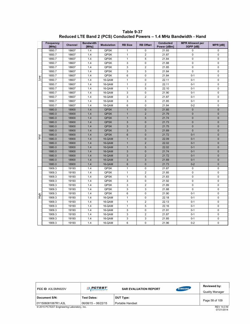
FCC ID: A3LSMN920V
SAR EVALUATION REPORT
Reviewed by:
Quality Manager
Document S/N: Test Dates: DUT Type: Page 58 of 109
0Y1506081067R1.A3L 06/08/15 – 06/22/15 Portable Handset © 2015 PCTEST Engineering Laboratory, Inc. REV 14.0 M 07/21/2014
Table 9-37 Reduced LTE Band 2 (PCS) Conducted Powers – 1.4 MHz Bandwidth - Hand
Frequency [MHz]
ChannelBandwidth
[MHz]Modulation RB Size RB Offset
Conducted Power [dBm]
MPR Allowed per 3GPP [dB]
MPR [dB]
1850.7 18607 1.4 QPSK 1 0 21.93 0 0
1850.7 18607 1.4 QPSK 1 2 21.87 0 0
1850.7 18607 1.4 QPSK 1 5 21.84 0 0
1850.7 18607 1.4 QPSK 3 0 21.88 0 0
1850.7 18607 1.4 QPSK 3 2 21.85 0 0
1850.7 18607 1.4 QPSK 3 3 21.84 0 0
1850.7 18607 1.4 QPSK 6 0 21.84 0-1 0
1850.7 18607 1.4 16-QAM 1 0 22.11 0-1 0
1850.7 18607 1.4 16-QAM 1 2 22.11 0-1 0
1850.7 18607 1.4 16-QAM 1 5 22.10 0-1 0
1850.7 18607 1.4 16-QAM 3 0 21.90 0-1 0
1850.7 18607 1.4 16-QAM 3 2 21.87 0-1 0
1850.7 18607 1.4 16-QAM 3 3 21.85 0-1 0
1850.7 18607 1.4 16-QAM 6 0 21.84 0-2 0
1880.0 18900 1.4 QPSK 1 0 21.85 0 0
1880.0 18900 1.4 QPSK 1 2 21.79 0 0
1880.0 18900 1.4 QPSK 1 5 21.74 0 0
1880.0 18900 1.4 QPSK 3 0 21.73 0 0
1880.0 18900 1.4 QPSK 3 2 21.75 0 0
1880.0 18900 1.4 QPSK 3 3 21.69 0 0
1880.0 18900 1.4 QPSK 6 0 21.72 0-1 0
1880.0 18900 1.4 16-QAM 1 0 22.09 0-1 0
1880.0 18900 1.4 16-QAM 1 2 22.02 0-1 0
1880.0 18900 1.4 16-QAM 1 5 22.02 0-1 0
1880.0 18900 1.4 16-QAM 3 0 21.74 0-1 0
1880.0 18900 1.4 16-QAM 3 2 21.72 0-1 0
1880.0 18900 1.4 16-QAM 3 3 21.69 0-1 0
1880.0 18900 1.4 16-QAM 6 0 21.73 0-2 0
1909.3 19193 1.4 QPSK 1 0 21.87 0 0
1909.3 19193 1.4 QPSK 1 2 21.85 0 0
1909.3 19193 1.4 QPSK 1 5 21.83 0 0
1909.3 19193 1.4 QPSK 3 0 21.92 0 0
1909.3 19193 1.4 QPSK 3 2 21.89 0 0
1909.3 19193 1.4 QPSK 3 3 21.88 0 0
1909.3 19193 1.4 QPSK 6 0 21.90 0-1 0
1909.3 19193 1.4 16-QAM 1 0 22.18 0-1 0
1909.3 19193 1.4 16-QAM 1 2 22.13 0-1 0
1909.3 19193 1.4 16-QAM 1 5 22.16 0-1 0
1909.3 19193 1.4 16-QAM 3 0 21.91 0-1 0
1909.3 19193 1.4 16-QAM 3 2 21.87 0-1 0
1909.3 19193 1.4 16-QAM 3 3 21.85 0-1 0
1909.3 19193 1.4 16-QAM 6 0 21.96 0-2 0
High
Low
Mid

FCC ID: A3LSMN920V
SAR EVALUATION REPORT
Reviewed by:
Quality Manager
Document S/N: Test Dates: DUT Type: Page 59 of 109
0Y1506081067R1.A3L 06/08/15 – 06/22/15 Portable Handset © 2015 PCTEST Engineering Laboratory, Inc. REV 14.0 M 07/21/2014
9.5.3 Reduced LTE Band 2 (PCS) Conducted Powers - Hotspot
Table 9-38 Reduced LTE Band 2 (PCS) Conducted Powers –20 MHz Bandwidth - Hotspot
Frequency [MHz]
ChannelBandwidth
[MHz]Modulation RB Size RB Offset
Conducted Power [dBm]
MPR Allowed per 3GPP [dB]
MPR [dB]
1860 18700 20 QPSK 1 0 20.69 0 0
1860 18700 20 QPSK 1 50 20.54 0 0
1860 18700 20 QPSK 1 99 20.57 0 0
1860 18700 20 QPSK 50 0 20.60 0-1 0
1860 18700 20 QPSK 50 25 20.46 0-1 0
1860 18700 20 QPSK 50 50 20.56 0-1 0
1860 18700 20 QPSK 100 0 20.48 0-1 0
1860 18700 20 16QAM 1 0 20.80 0-1 0
1860 18700 20 16QAM 1 50 20.69 0-1 0
1860 18700 20 16QAM 1 99 20.75 0-1 0
1860 18700 20 16QAM 50 0 20.55 0-2 0
1860 18700 20 16QAM 50 25 20.45 0-2 0
1860 18700 20 16QAM 50 50 20.53 0-2 0
1860 18700 20 16QAM 100 0 20.50 0-2 0
1880.0 18900 20 QPSK 1 0 20.75 0 0
1880.0 18900 20 QPSK 1 50 20.49 0 0
1880.0 18900 20 QPSK 1 99 20.51 0 0
1880.0 18900 20 QPSK 50 0 20.60 0-1 0
1880.0 18900 20 QPSK 50 25 20.57 0-1 0
1880.0 18900 20 QPSK 50 50 20.50 0-1 0
1880.0 18900 20 QPSK 100 0 20.58 0-1 0
1880.0 18900 20 16QAM 1 0 20.70 0-1 0
1880.0 18900 20 16QAM 1 50 20.53 0-1 0
1880.0 18900 20 16QAM 1 99 20.71 0-1 0
1880.0 18900 20 16QAM 50 0 20.61 0-2 0
1880.0 18900 20 16QAM 50 25 20.55 0-2 0
1880.0 18900 20 16QAM 50 50 20.50 0-2 0
1880.0 18900 20 16QAM 100 0 20.57 0-2 0
1900 19100 20 QPSK 1 0 20.78 0 0
1900 19100 20 QPSK 1 50 20.41 0 0
1900 19100 20 QPSK 1 99 20.49 0 0
1900 19100 20 QPSK 50 0 20.61 0-1 0
1900 19100 20 QPSK 50 25 20.47 0-1 0
1900 19100 20 QPSK 50 50 20.49 0-1 0
1900 19100 20 QPSK 100 0 20.50 0-1 0
1900 19100 20 16QAM 1 0 20.78 0-1 0
1900 19100 20 16QAM 1 50 20.65 0-1 0
1900 19100 20 16QAM 1 99 20.69 0-1 0
1900 19100 20 16QAM 50 0 20.55 0-2 0
1900 19100 20 16QAM 50 25 20.47 0-2 0
1900 19100 20 16QAM 50 50 20.44 0-2 0
1900 19100 20 16QAM 100 0 20.49 0-2 0
High
Low
Mid

FCC ID: A3LSMN920V
SAR EVALUATION REPORT
Reviewed by:
Quality Manager
Document S/N: Test Dates: DUT Type: Page 60 of 109
0Y1506081067R1.A3L 06/08/15 – 06/22/15 Portable Handset © 2015 PCTEST Engineering Laboratory, Inc. REV 14.0 M 07/21/2014
Table 9-39 Reduced LTE Band 2 (PCS) Conducted Powers –15 MHz Bandwidth - Hotspot
Frequency [MHz]
ChannelBandwidth
[MHz]Modulation RB Size RB Offset
Conducted Power [dBm]
MPR Allowed per 3GPP [dB]
MPR [dB]
1857.5 18675 15 QPSK 1 0 20.28 0 0
1857.5 18675 15 QPSK 1 36 20.52 0 0
1857.5 18675 15 QPSK 1 74 20.46 0 0
1857.5 18675 15 QPSK 36 0 20.41 0-1 0
1857.5 18675 15 QPSK 36 18 20.35 0-1 0
1857.5 18675 15 QPSK 36 37 20.18 0-1 0
1857.5 18675 15 QPSK 75 0 20.26 0-1 0
1857.5 18675 15 16QAM 1 0 20.65 0-1 0
1857.5 18675 15 16QAM 1 36 20.17 0-1 0
1857.5 18675 15 16QAM 1 74 20.29 0-1 0
1857.5 18675 15 16QAM 36 0 20.49 0-2 0
1857.5 18675 15 16QAM 36 18 20.36 0-2 0
1857.5 18675 15 16QAM 36 37 20.26 0-2 0
1857.5 18675 15 16QAM 75 0 20.04 0-2 0
1880.0 18900 15 QPSK 1 0 20.58 0 0
1880.0 18900 15 QPSK 1 36 20.17 0 0
1880.0 18900 15 QPSK 1 74 20.45 0 0
1880.0 18900 15 QPSK 36 0 20.21 0-1 0
1880.0 18900 15 QPSK 36 18 20.30 0-1 0
1880.0 18900 15 QPSK 36 37 20.45 0-1 0
1880.0 18900 15 QPSK 75 0 20.02 0-1 0
1880.0 18900 15 16QAM 1 0 20.69 0-1 0
1880.0 18900 15 16QAM 1 36 20.38 0-1 0
1880.0 18900 15 16QAM 1 74 20.37 0-1 0
1880.0 18900 15 16QAM 36 0 20.58 0-2 0
1880.0 18900 15 16QAM 36 18 20.20 0-2 0
1880.0 18900 15 16QAM 36 37 20.35 0-2 0
1880.0 18900 15 16QAM 75 0 20.39 0-2 0
1902.5 19125 15 QPSK 1 0 20.52 0 0
1902.5 19125 15 QPSK 1 36 20.05 0 0
1902.5 19125 15 QPSK 1 74 20.28 0 0
1902.5 19125 15 QPSK 36 0 20.34 0-1 0
1902.5 19125 15 QPSK 36 18 20.09 0-1 0
1902.5 19125 15 QPSK 36 37 20.35 0-1 0
1902.5 19125 15 QPSK 75 0 20.29 0-1 0
1902.5 19125 15 16QAM 1 0 20.22 0-1 0
1902.5 19125 15 16QAM 1 36 20.50 0-1 0
1902.5 19125 15 16QAM 1 74 20.31 0-1 0
1902.5 19125 15 16QAM 36 0 20.13 0-2 0
1902.5 19125 15 16QAM 36 18 20.08 0-2 0
1902.5 19125 15 16QAM 36 37 20.22 0-2 0
1902.5 19125 15 16QAM 75 0 20.09 0-2 0
Mid
High
Low

FCC ID: A3LSMN920V
SAR EVALUATION REPORT
Reviewed by:
Quality Manager
Document S/N: Test Dates: DUT Type: Page 61 of 109
0Y1506081067R1.A3L 06/08/15 – 06/22/15 Portable Handset © 2015 PCTEST Engineering Laboratory, Inc. REV 14.0 M 07/21/2014
Table 9-40 Reduced LTE Band 2 (PCS) Conducted Powers –10 MHz Bandwidth - Hotspot
Frequency [MHz]
ChannelBandwidth
[MHz]Modulation RB Size RB Offset
Conducted Power [dBm]
MPR Allowed per 3GPP [dB]
MPR [dB]
1855 18650 10 QPSK 1 0 20.19 0 0
1855 18650 10 QPSK 1 25 20.72 0 0
1855 18650 10 QPSK 1 49 20.18 0 0
1855 18650 10 QPSK 25 0 20.39 0-1 0
1855 18650 10 QPSK 25 12 20.33 0-1 0
1855 18650 10 QPSK 25 25 20.26 0-1 0
1855 18650 10 QPSK 50 0 20.04 0-1 0
1855 18650 10 16QAM 1 0 20.43 0-1 0
1855 18650 10 16QAM 1 25 20.05 0-1 0
1855 18650 10 16QAM 1 49 20.49 0-1 0
1855 18650 10 16QAM 25 0 20.63 0-2 0
1855 18650 10 16QAM 25 12 20.26 0-2 0
1855 18650 10 16QAM 25 25 20.22 0-2 0
1855 18650 10 16QAM 50 0 20.27 0-2 0
1880.0 18900 10 QPSK 1 0 20.47 0 0
1880.0 18900 10 QPSK 1 25 20.23 0 0
1880.0 18900 10 QPSK 1 49 20.28 0 0
1880.0 18900 10 QPSK 25 0 20.08 0-1 0
1880.0 18900 10 QPSK 25 12 20.58 0-1 0
1880.0 18900 10 QPSK 25 25 20.53 0-1 0
1880.0 18900 10 QPSK 50 0 20.18 0-1 0
1880.0 18900 10 16QAM 1 0 20.58 0-1 0
1880.0 18900 10 16QAM 1 25 20.55 0-1 0
1880.0 18900 10 16QAM 1 49 20.43 0-1 0
1880.0 18900 10 16QAM 25 0 20.80 0-2 0
1880.0 18900 10 16QAM 25 12 20.40 0-2 0
1880.0 18900 10 16QAM 25 25 20.10 0-2 0
1880.0 18900 10 16QAM 50 0 20.25 0-2 0
1905 19150 10 QPSK 1 0 20.66 0 0
1905 19150 10 QPSK 1 25 20.29 0 0
1905 19150 10 QPSK 1 49 20.30 0 0
1905 19150 10 QPSK 25 0 20.10 0-1 0
1905 19150 10 QPSK 25 12 20.10 0-1 0
1905 19150 10 QPSK 25 25 20.50 0-1 0
1905 19150 10 QPSK 50 0 20.59 0-1 0
1905 19150 10 16QAM 1 0 20.29 0-1 0
1905 19150 10 16QAM 1 25 20.67 0-1 0
1905 19150 10 16QAM 1 49 20.07 0-1 0
1905 19150 10 16QAM 25 0 20.38 0-2 0
1905 19150 10 16QAM 25 12 20.14 0-2 0
1905 19150 10 16QAM 25 25 20.22 0-2 0
1905 19150 10 16QAM 50 0 20.06 0-2 0
Low
Mid
High

FCC ID: A3LSMN920V
SAR EVALUATION REPORT
Reviewed by:
Quality Manager
Document S/N: Test Dates: DUT Type: Page 62 of 109
0Y1506081067R1.A3L 06/08/15 – 06/22/15 Portable Handset © 2015 PCTEST Engineering Laboratory, Inc. REV 14.0 M 07/21/2014
Table 9-41 Reduced LTE Band 2 (PCS) Conducted Powers –5 MHz Bandwidth - Hotspot
Frequency [MHz]
ChannelBandwidth
[MHz]Modulation RB Size RB Offset
Conducted Power [dBm]
MPR Allowed per 3GPP [dB]
MPR [dB]
1852.5 18625 5 QPSK 1 0 20.10 0 0
1852.5 18625 5 QPSK 1 12 20.79 0 0
1852.5 18625 5 QPSK 1 24 20.19 0 0
1852.5 18625 5 QPSK 12 0 20.63 0-1 0
1852.5 18625 5 QPSK 12 6 20.70 0-1 0
1852.5 18625 5 QPSK 12 13 20.52 0-1 0
1852.5 18625 5 QPSK 25 0 20.58 0-1 0
1852.5 18625 5 16-QAM 1 0 20.20 0-1 0
1852.5 18625 5 16-QAM 1 12 20.60 0-1 0
1852.5 18625 5 16-QAM 1 24 20.51 0-1 0
1852.5 18625 5 16-QAM 12 0 20.78 0-2 0
1852.5 18625 5 16-QAM 12 6 20.66 0-2 0
1852.5 18625 5 16-QAM 12 13 20.26 0-2 0
1852.5 18625 5 16-QAM 25 0 20.32 0-2 0
1880.0 18900 5 QPSK 1 0 20.19 0 0
1880.0 18900 5 QPSK 1 12 20.17 0 0
1880.0 18900 5 QPSK 1 24 20.38 0 0
1880.0 18900 5 QPSK 12 0 20.15 0-1 0
1880.0 18900 5 QPSK 12 6 20.38 0-1 0
1880.0 18900 5 QPSK 12 13 20.49 0-1 0
1880.0 18900 5 QPSK 25 0 20.22 0-1 0
1880.0 18900 5 16-QAM 1 0 20.56 0-1 0
1880.0 18900 5 16-QAM 1 12 20.56 0-1 0
1880.0 18900 5 16-QAM 1 24 20.71 0-1 0
1880.0 18900 5 16-QAM 12 0 20.59 0-2 0
1880.0 18900 5 16-QAM 12 6 20.29 0-2 0
1880.0 18900 5 16-QAM 12 13 20.36 0-2 0
1880.0 18900 5 16-QAM 25 0 20.55 0-2 0
1907.5 19175 5 QPSK 1 0 20.94 0 0
1907.5 19175 5 QPSK 1 12 20.28 0 0
1907.5 19175 5 QPSK 1 24 20.22 0 0
1907.5 19175 5 QPSK 12 0 20.17 0-1 0
1907.5 19175 5 QPSK 12 6 20.03 0-1 0
1907.5 19175 5 QPSK 12 13 20.49 0-1 0
1907.5 19175 5 QPSK 25 0 20.47 0-1 0
1907.5 19175 5 16-QAM 1 0 20.31 0-1 0
1907.5 19175 5 16-QAM 1 12 20.96 0-1 0
1907.5 19175 5 16-QAM 1 24 20.68 0-1 0
1907.5 19175 5 16-QAM 12 0 20.38 0-2 0
1907.5 19175 5 16-QAM 12 6 20.34 0-2 0
1907.5 19175 5 16-QAM 12 13 20.41 0-2 0
1907.5 19175 5 16-QAM 25 0 20.70 0-2 0
Mid
High
Low

FCC ID: A3LSMN920V
SAR EVALUATION REPORT
Reviewed by:
Quality Manager
Document S/N: Test Dates: DUT Type: Page 63 of 109
0Y1506081067R1.A3L 06/08/15 – 06/22/15 Portable Handset © 2015 PCTEST Engineering Laboratory, Inc. REV 14.0 M 07/21/2014
Table 9-42 Reduced LTE Band 2 (PCS) Conducted Powers –3 MHz Bandwidth - Hotspot
Frequency [MHz]
ChannelBandwidth
[MHz]Modulation RB Size RB Offset
Conducted Power [dBm]
MPR Allowed per 3GPP [dB]
MPR [dB]
1851.5 18615 3 QPSK 1 0 20.38 0 0
1851.5 18615 3 QPSK 1 7 20.84 0 0
1851.5 18615 3 QPSK 1 14 20.13 0 0
1851.5 18615 3 QPSK 8 0 20.52 0-1 0
1851.5 18615 3 QPSK 8 4 20.60 0-1 0
1851.5 18615 3 QPSK 8 7 20.37 0-1 0
1851.5 18615 3 QPSK 15 0 20.51 0-1 0
1851.5 18615 3 16-QAM 1 0 20.54 0-1 0
1851.5 18615 3 16-QAM 1 7 20.03 0-1 0
1851.5 18615 3 16-QAM 1 14 20.65 0-1 0
1851.5 18615 3 16-QAM 8 0 20.80 0-2 0
1851.5 18615 3 16-QAM 8 4 20.47 0-2 0
1851.5 18615 3 16-QAM 8 7 20.45 0-2 0
1851.5 18615 3 16-QAM 15 0 20.39 0-2 0
1880.0 18900 3 QPSK 1 0 20.52 0 0
1880.0 18900 3 QPSK 1 7 20.05 0 0
1880.0 18900 3 QPSK 1 14 20.18 0 0
1880.0 18900 3 QPSK 8 0 20.59 0-1 0
1880.0 18900 3 QPSK 8 4 20.44 0-1 0
1880.0 18900 3 QPSK 8 7 20.77 0-1 0
1880.0 18900 3 QPSK 15 0 20.16 0-1 0
1880.0 18900 3 16-QAM 1 0 20.52 0-1 0
1880.0 18900 3 16-QAM 1 7 20.54 0-1 0
1880.0 18900 3 16-QAM 1 14 20.63 0-1 0
1880.0 18900 3 16-QAM 8 0 20.43 0-2 0
1880.0 18900 3 16-QAM 8 4 20.44 0-2 0
1880.0 18900 3 16-QAM 8 7 20.66 0-2 0
1880.0 18900 3 16-QAM 15 0 20.85 0-2 0
1908.5 19185 3 QPSK 1 0 20.74 0 0
1908.5 19185 3 QPSK 1 7 20.43 0 0
1908.5 19185 3 QPSK 1 14 20.02 0 0
1908.5 19185 3 QPSK 8 0 20.35 0-1 0
1908.5 19185 3 QPSK 8 4 20.27 0-1 0
1908.5 19185 3 QPSK 8 7 20.65 0-1 0
1908.5 19185 3 QPSK 15 0 20.64 0-1 0
1908.5 19185 3 16-QAM 1 0 20.51 0-1 0
1908.5 19185 3 16-QAM 1 7 20.93 0-1 0
1908.5 19185 3 16-QAM 1 14 20.48 0-1 0
1908.5 19185 3 16-QAM 8 0 20.14 0-2 0
1908.5 19185 3 16-QAM 8 4 20.54 0-2 0
1908.5 19185 3 16-QAM 8 7 20.63 0-2 0
1908.5 19185 3 16-QAM 15 0 20.09 0-2 0
Low
Mid
High
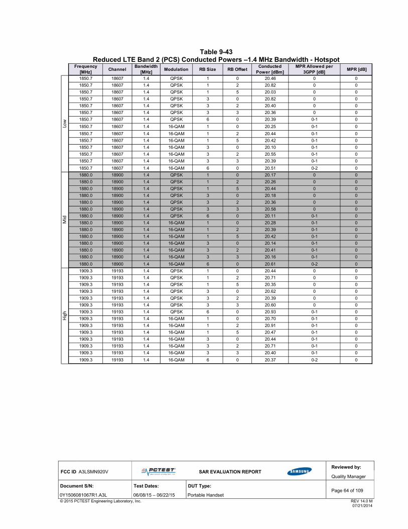
FCC ID: A3LSMN920V
SAR EVALUATION REPORT
Reviewed by:
Quality Manager
Document S/N: Test Dates: DUT Type: Page 64 of 109
0Y1506081067R1.A3L 06/08/15 – 06/22/15 Portable Handset © 2015 PCTEST Engineering Laboratory, Inc. REV 14.0 M 07/21/2014
Table 9-43 Reduced LTE Band 2 (PCS) Conducted Powers –1.4 MHz Bandwidth - Hotspot
Frequency [MHz]
ChannelBandwidth
[MHz]Modulation RB Size RB Offset
Conducted Power [dBm]
MPR Allowed per 3GPP [dB]
MPR [dB]
1850.7 18607 1.4 QPSK 1 0 20.46 0 0
1850.7 18607 1.4 QPSK 1 2 20.82 0 0
1850.7 18607 1.4 QPSK 1 5 20.03 0 0
1850.7 18607 1.4 QPSK 3 0 20.82 0 0
1850.7 18607 1.4 QPSK 3 2 20.40 0 0
1850.7 18607 1.4 QPSK 3 3 20.36 0 0
1850.7 18607 1.4 QPSK 6 0 20.39 0-1 0
1850.7 18607 1.4 16-QAM 1 0 20.25 0-1 0
1850.7 18607 1.4 16-QAM 1 2 20.44 0-1 0
1850.7 18607 1.4 16-QAM 1 5 20.42 0-1 0
1850.7 18607 1.4 16-QAM 3 0 20.10 0-1 0
1850.7 18607 1.4 16-QAM 3 2 20.55 0-1 0
1850.7 18607 1.4 16-QAM 3 3 20.39 0-1 0
1850.7 18607 1.4 16-QAM 6 0 20.51 0-2 0
1880.0 18900 1.4 QPSK 1 0 20.17 0 0
1880.0 18900 1.4 QPSK 1 2 20.26 0 0
1880.0 18900 1.4 QPSK 1 5 20.44 0 0
1880.0 18900 1.4 QPSK 3 0 20.18 0 0
1880.0 18900 1.4 QPSK 3 2 20.36 0 0
1880.0 18900 1.4 QPSK 3 3 20.58 0 0
1880.0 18900 1.4 QPSK 6 0 20.11 0-1 0
1880.0 18900 1.4 16-QAM 1 0 20.28 0-1 0
1880.0 18900 1.4 16-QAM 1 2 20.39 0-1 0
1880.0 18900 1.4 16-QAM 1 5 20.42 0-1 0
1880.0 18900 1.4 16-QAM 3 0 20.14 0-1 0
1880.0 18900 1.4 16-QAM 3 2 20.41 0-1 0
1880.0 18900 1.4 16-QAM 3 3 20.16 0-1 0
1880.0 18900 1.4 16-QAM 6 0 20.61 0-2 0
1909.3 19193 1.4 QPSK 1 0 20.44 0 0
1909.3 19193 1.4 QPSK 1 2 20.71 0 0
1909.3 19193 1.4 QPSK 1 5 20.35 0 0
1909.3 19193 1.4 QPSK 3 0 20.62 0 0
1909.3 19193 1.4 QPSK 3 2 20.39 0 0
1909.3 19193 1.4 QPSK 3 3 20.60 0 0
1909.3 19193 1.4 QPSK 6 0 20.93 0-1 0
1909.3 19193 1.4 16-QAM 1 0 20.70 0-1 0
1909.3 19193 1.4 16-QAM 1 2 20.91 0-1 0
1909.3 19193 1.4 16-QAM 1 5 20.47 0-1 0
1909.3 19193 1.4 16-QAM 3 0 20.44 0-1 0
1909.3 19193 1.4 16-QAM 3 2 20.71 0-1 0
1909.3 19193 1.4 16-QAM 3 3 20.40 0-1 0
1909.3 19193 1.4 16-QAM 6 0 20.37 0-2 0
Mid
High
Low
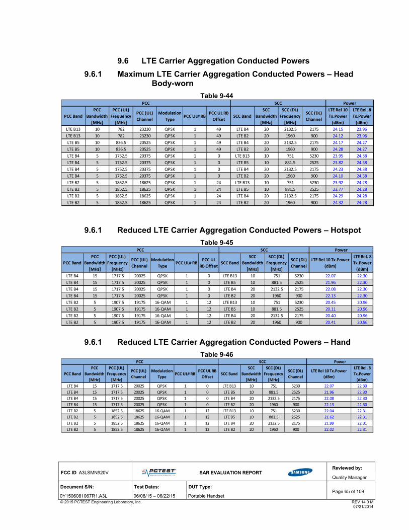
FCC ID: A3LSMN920V
SAR EVALUATION REPORT
Reviewed by:
Quality Manager
Document S/N: Test Dates: DUT Type: Page 65 of 109
0Y1506081067R1.A3L 06/08/15 – 06/22/15 Portable Handset © 2015 PCTEST Engineering Laboratory, Inc. REV 14.0 M 07/21/2014
9.6 LTE Carrier Aggregation Conducted Powers
9.6.1 Maximum LTE Carrier Aggregation Conducted Powers – Head Body-worn
Table 9-44
9.6.1 Reduced LTE Carrier Aggregation Conducted Powers – Hotspot
Table 9-45
9.6.1 Reduced LTE Carrier Aggregation Conducted Powers – Hand
Table 9-46
PCC Band
PCC
Bandwidth
[MHz]
PCC (UL)
Frequency
[MHz]
PCC (UL)
Channel
Modulation
TypePCC UL# RB
PCC UL RB
OffsetSCC Band
SCC
Bandwidth
[MHz]
SCC (DL)
Frequency
[MHz]
SCC (DL)
Channel
LTE Rel 10
Tx.Power
(dBm)
LTE Rel. 8
Tx.Power
(dBm)
LTE B13 10 782 23230 QPSK 1 49 LTE B4 20 2132.5 2175 24.15 23.96
LTE B13 10 782 23230 QPSK 1 49 LTE B2 20 1960 900 24.12 23.96
LTE B5 10 836.5 20525 QPSK 1 49 LTE B4 20 2132.5 2175 24.17 24.27
LTE B5 10 836.5 20525 QPSK 1 49 LTE B2 20 1960 900 24.28 24.27
LTE B4 5 1752.5 20375 QPSK 1 0 LTE B13 10 751 5230 23.95 24.38
LTE B4 5 1752.5 20375 QPSK 1 0 LTE B5 10 881.5 2525 23.82 24.38
LTE B4 5 1752.5 20375 QPSK 1 0 LTE B4 20 2132.5 2175 24.23 24.38
LTE B4 5 1752.5 20375 QPSK 1 0 LTE B2 20 1960 900 24.10 24.38
LTE B2 5 1852.5 18625 QPSK 1 24 LTE B13 10 751 5230 23.92 24.28
LTE B2 5 1852.5 18625 QPSK 1 24 LTE B5 10 881.5 2525 23.77 24.28
LTE B2 5 1852.5 18625 QPSK 1 24 LTE B4 20 2132.5 2175 24.29 24.28
LTE B2 5 1852.5 18625 QPSK 1 24 LTE B2 20 1960 900 24.32 24.28
PCC SCC Power
PCC Band
PCC
Bandwidth
[MHz]
PCC (UL)
Frequency
[MHz]
PCC (UL)
Channel
Modulation
TypePCC UL# RB
PCC UL
RB OffsetSCC Band
SCC
Bandwidth
[MHz]
SCC (DL)
Frequency
[MHz]
SCC (DL)
Channel
LTE Rel 10 Tx.Power
(dBm)
LTE Rel. 8
Tx.Power
(dBm)
LTE B4 15 1717.5 20025 QPSK 1 0 LTE B13 10 751 5230 22.07 22.30
LTE B4 15 1717.5 20025 QPSK 1 0 LTE B5 10 881.5 2525 21.96 22.30
LTE B4 15 1717.5 20025 QPSK 1 0 LTE B4 20 2132.5 2175 22.08 22.30
LTE B4 15 1717.5 20025 QPSK 1 0 LTE B2 20 1960 900 22.13 22.30
LTE B2 5 1907.5 19175 16‐QAM 1 12 LTE B13 10 751 5230 20.45 20.96
LTE B2 5 1907.5 19175 16‐QAM 1 12 LTE B5 10 881.5 2525 20.11 20.96
LTE B2 5 1907.5 19175 16‐QAM 1 12 LTE B4 20 2132.5 2175 20.40 20.96
LTE B2 5 1907.5 19175 16‐QAM 1 12 LTE B2 20 1960 900 20.41 20.96
PCC SCC Power
PCC Band
PCC
Bandwidth
[MHz]
PCC (UL)
Frequency
[MHz]
PCC (UL)
Channel
Modulation
TypePCC UL# RB
PCC UL RB
OffsetSCC Band
SCC
Bandwidth
[MHz]
SCC (DL)
Frequency
[MHz]
SCC (DL)
Channel
LTE Rel 10 Tx.Power
(dBm)
LTE Rel. 8
Tx.Power
(dBm)
LTE B4 15 1717.5 20025 QPSK 1 0 LTE B13 10 751 5230 22.07 22.30
LTE B4 15 1717.5 20025 QPSK 1 0 LTE B5 10 881.5 2525 21.96 22.30
LTE B4 15 1717.5 20025 QPSK 1 0 LTE B4 20 2132.5 2175 22.08 22.30
LTE B4 15 1717.5 20025 QPSK 1 0 LTE B2 20 1960 900 22.13 22.30
LTE B2 5 1852.5 18625 16‐QAM 1 12 LTE B13 10 751 5230 22.04 22.31
LTE B2 5 1852.5 18625 16‐QAM 1 12 LTE B5 10 881.5 2525 21.62 22.31
LTE B2 5 1852.5 18625 16‐QAM 1 12 LTE B4 20 2132.5 2175 21.99 22.31
LTE B2 5 1852.5 18625 16‐QAM 1 12 LTE B2 20 1960 900 22.02 22.31
PCC SCC Power
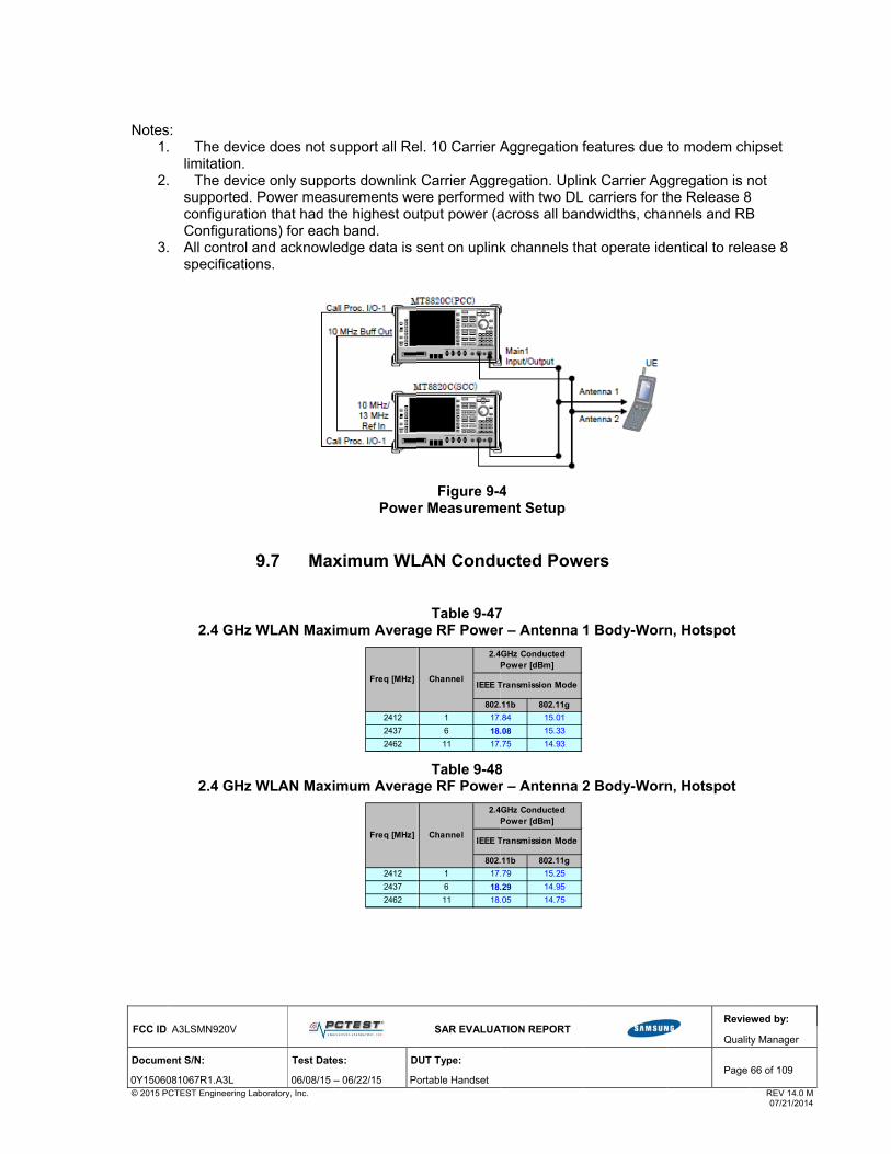
FCC ID
Docume
0Y15060© 2015 P
Notes1
2
3
: A3LSMN920V
ent S/N:
081067R1.A3L PCTEST Engineering L
s: . The devi
limitation. . The devi
supported.configuratiConfigurat
. All control specificatio
2.4 GHz
2.4 GHz
Test Date
06/08/15 Laboratory, Inc.
ce does not s
ce only suppo. Power meason that had thtions) for eachand acknowle
ons.
9.7 Max
z WLAN Maxi
z WLAN Maxi
es: D
– 06/22/15 P
support all Re
orts downlinksurements wehe highest ouh band. edge data is s
Powe
ximum WL
imum Averag
imum Averag
2412
2437
2462
Freq [MHz]
2412
2437
2462
Freq [MHz]
SAR EVALUA
DUT Type:
ortable Handset
el. 10 Carrier A
k Carrier Aggrere performedutput power (a
sent on uplink
Figure 9-4er Measureme
LAN Condu
Table 9-47ge RF Power
Table 9-48ge RF Power
802.
1 17.
6 18.
11 17.
Channel
2.4
IEEE T
802.
1 17.
6 18.
11 18.
Channel
2.4
IEEE T
ATION REPORT
Aggregation f
regation. Uplind with two DLacross all ban
k channels th
4 ent Setup
ucted Pow
7 r – Antenna 1
8 r – Antenna 2
.11b 802.11g
.84 15.01
.08 15.33
.75 14.93
4GHz Conducted Power [dBm]
Transmission Mode
.11b 802.11g
.79 15.25
.29 14.95
.05 14.75
4GHz Conducted Power [dBm]
Transmission Mode
features due
nk Carrier Ag carriers for th
ndwidths, cha
hat operate ide
ers
1 Body-Worn
2 Body-Worn
Revie
Qualit
Page
to modem ch
gregation is nhe Release 8
annels and RB
entical to rele
n, Hotspot
n, Hotspot
ewed by:
ty Manager
66 of 109
REV 14.0 M 07/21/2014
hipset
not 8 B
ease 8

FCC ID: A3LSMN920V
SAR EVALUATION REPORT
Reviewed by:
Quality Manager
Document S/N: Test Dates: DUT Type: Page 67 of 109
0Y1506081067R1.A3L 06/08/15 – 06/22/15 Portable Handset © 2015 PCTEST Engineering Laboratory, Inc. REV 14.0 M 07/21/2014
Table 9-49 5 GHz WLAN Maximum Average RF Power – Antenna 1 –Body-Worn, Hotspot, Hand
Table 9-50 5 GHz WLAN Maximum Average RF Power – Antenna 2 Body-Worn, Hotspot, Hand
5GHz (20MHz) Conducted Power [dBm]
IEEE Transmission Mode
802.11a
5180 36 15.16
5200 40 15.05
5220 44 15.15
5240 48 15.19
5260 52 14.98
5280 56 14.97
5300 60 15.04
5320 64 14.91
5500 100 15.11
5600 120 14.74
5620 124 14.85
5720 144 15.18
5745 149 15.48
5785 157 15.31
5825 165 15.23
Freq [MHz] Channel
5GHz (20MHz) Conducted Power [dBm]
IEEE Transmission Mode
802.11a
5180 36 15.22
5200 40 15.05
5220 44 15.04
5240 48 15.28
5260 52 15.33
5280 56 15.20
5300 60 15.19
5320 64 15.27
5500 100 15.15
5600 120 14.91
5620 124 14.92
5720 144 14.85
5745 149 14.83
5785 157 14.77
5825 165 14.71
Freq [MHz] Channel

FCC ID: A3LSMN920V
SAR EVALUATION REPORT
Reviewed by:
Quality Manager
Document S/N: Test Dates: DUT Type: Page 68 of 109
0Y1506081067R1.A3L 06/08/15 – 06/22/15 Portable Handset © 2015 PCTEST Engineering Laboratory, Inc. REV 14.0 M 07/21/2014
Table 9-51 5 GHz WLAN Maximum Average RF Power – MIMO Body-Worn, Hotspot, Hand
5GHz (20MHz) Conducted Power [dBm]
IEEE Transmission Mode
802.11 n
5180 36 16.27
5200 40 16.31
5220 44 16.30
5240 48 16.34
5260 52 15.94
5280 56 15.89
5300 60 15.94
5320 64 15.89
5500 100 16.27
5600 120 16.14
5620 124 15.95
5720 144 16.16
5745 149 16.30
5785 157 16.19
5825 165 16.13
Freq [MHz] Channel
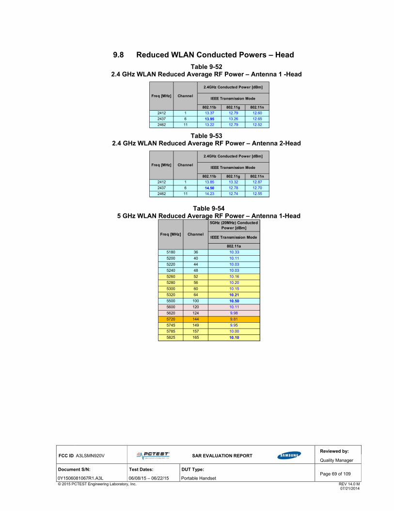
FCC ID: A3LSMN920V
SAR EVALUATION REPORT
Reviewed by:
Quality Manager
Document S/N: Test Dates: DUT Type: Page 69 of 109
0Y1506081067R1.A3L 06/08/15 – 06/22/15 Portable Handset © 2015 PCTEST Engineering Laboratory, Inc. REV 14.0 M 07/21/2014
9.8 Reduced WLAN Conducted Powers – Head
Table 9-52 2.4 GHz WLAN Reduced Average RF Power – Antenna 1 -Head
Table 9-53 2.4 GHz WLAN Reduced Average RF Power – Antenna 2-Head
Table 9-54 5 GHz WLAN Reduced Average RF Power – Antenna 1-Head
802.11b 802.11g 802.11n
2412 1 13.37 12.79 12.60
2437 6 13.95 13.26 12.65
2462 11 13.22 12.79 12.52
Freq [MHz] ChannelIEEE Transmission Mode
2.4GHz Conducted Power [dBm]
802.11b 802.11g 802.11n
2412 1 13.85 13.32 12.87
2437 6 14.50 12.78 12.70
2462 11 14.23 12.74 12.55
Freq [MHz] ChannelIEEE Transmission Mode
2.4GHz Conducted Power [dBm]
5GHz (20MHz) Conducted Power [dBm]
IEEE Transmission Mode
802.11a
5180 36 10.33
5200 40 10.11
5220 44 10.03
5240 48 10.03
5260 52 10.16
5280 56 10.20
5300 60 10.15
5320 64 10.21
5500 100 10.50
5600 120 10.11
5620 124 9.98
5720 144 9.81
5745 149 9.95
5785 157 10.00
5825 165 10.10
Freq [MHz] Channel

FCC ID: A3LSMN920V
SAR EVALUATION REPORT
Reviewed by:
Quality Manager
Document S/N: Test Dates: DUT Type: Page 70 of 109
0Y1506081067R1.A3L 06/08/15 – 06/22/15 Portable Handset © 2015 PCTEST Engineering Laboratory, Inc. REV 14.0 M 07/21/2014
Table 9-55 5 GHz WLAN Reduced Average RF Power – Antenna 2-Head
Justification for test configurations for WLAN per KDB Publication 248227 D01v02r01:
Power measurements were performed for the transmission mode configuration with the highest maximum output power specified for production units.
For transmission modes with the same maximum output power specification, powers were measured for the largest channel bandwidth, lowest order modulation and lowest data rate.
For transmission modes with identical maximum specified output power, channel bandwidth, modulation and data rates, power measurements were required for all identical configurations.
For each transmission mode configuration, powers were measured for the highest and lowest channels; and at the mid-band channel(s) when there were at least 3 channels supported. For configurations with multiple mid-band channels, due to an even number of channels, both channels were measured.
The bolded data rate and channel above were tested for SAR.
Figure 9-5
Power Measurement Setup for Bandwidths < 50 MHz
5GHz (20MHz) Conducted Power [dBm]
IEEE Transmission Mode
802.11a
5180 36 9.86
5200 40 10.15
5220 44 10.14
5240 48 10.06
5260 52 9.95
5280 56 10.04
5300 60 9.94
5320 64 10.00
5500 100 9.77
5600 120 9.61
5620 124 9.72
5720 144 9.62
5745 149 10.49
5785 157 10.42
5825 165 10.27
Freq [MHz] Channel

FCC ID: A3LSMN920V
SAR EVALUATION REPORT
Reviewed by:
Quality Manager
Document S/N: Test Dates: DUT Type: Page 71 of 109
0Y1506081067R1.A3L 06/08/15 – 06/22/15 Portable Handset © 2015 PCTEST Engineering Laboratory, Inc. REV 14.0 M 07/21/2014
10 S Y S T E M V E R I F I C A T I O N
10.1 Tissue Verification
Table 10-1 Measured Tissue Properties (Head)
Calibrated for Tests Performed
on:Tissue Type
Tissue Temp During Calibration (C˚)
Measured Frequency
(MHz)
Measured Conductivity, σ
(S/m)
Measured Dielectric
Constant, ε
TARGET Conductivity, σ
(S/m)
TARGET Dielectric
Constant, ε% dev σ % dev ε
740 0.883 42.129 0.893 41.994 -1.12% 0.32%
755 0.898 41.978 0.894 41.916 0.45% 0.15%
770 0.914 41.734 0.895 41.838 2.12% -0.25%
785 0.926 41.571 0.896 41.760 3.35% -0.45%
820 0.883 40.658 0.899 41.578 -1.78% -2.21%
835 0.898 40.464 0.900 41.500 -0.22% -2.50%
850 0.912 40.263 0.916 41.500 -0.44% -2.98%
820 0.882 40.453 0.899 41.578 -1.89% -2.71%
835 0.894 40.228 0.900 41.500 -0.67% -3.07%
850 0.910 40.029 0.916 41.500 -0.66% -3.54%
1710 1.310 39.272 1.348 40.142 -2.82% -2.17%
1750 1.350 39.087 1.371 40.079 -1.53% -2.48%
1790 1.389 38.941 1.394 40.016 -0.36% -2.69%
1850 1.375 40.765 1.400 40.000 -1.79% 1.91%
1880 1.404 40.630 1.400 40.000 0.29% 1.58%
1910 1.439 40.531 1.400 40.000 2.79% 1.33%
1850 1.364 39.792 1.400 40.000 -2.57% -0.52%
1880 1.395 39.656 1.400 40.000 -0.36% -0.86%
1910 1.429 39.558 1.400 40.000 2.07% -1.11%
1850 1.343 40.472 1.400 40.000 -4.07% 1.18%
1880 1.379 40.400 1.400 40.000 -1.50% 1.00%
1910 1.412 40.262 1.400 40.000 0.86% 0.66%
2400 1.764 39.081 1.756 39.289 0.46% -0.53%
2450 1.825 38.879 1.800 39.200 1.39% -0.82%
2500 1.883 38.670 1.855 39.136 1.51% -1.19%
5280 4.710 34.444 4.737 35.894 -0.57% -4.04%
5300 4.720 34.391 4.758 35.871 -0.80% -4.13%
5320 4.739 34.329 4.778 35.849 -0.82% -4.24%
5500 4.950 34.051 4.963 35.643 -0.26% -4.47%
5580 5.002 33.923 5.045 35.551 -0.85% -4.58%
5700 5.140 33.754 5.168 35.414 -0.54% -4.69%
5745 5.206 33.650 5.214 35.363 -0.15% -4.84%
5800 5.268 33.587 5.270 35.300 -0.04% -4.85%
5805 5.268 33.581 5.275 35.294 -0.13% -4.85%
5825 5.276 33.555 5.296 35.271 -0.38% -4.87%
06/10/2015 750H 23.8
835H06/08/2015
06/15/2015
1900H06/11/2015
835H06/17/2015
1750H06/12/2015
2400H06/17/2015
1900H06/14/2015
1900H06/18/2015
5200H-5800H
21.5
21.4
22.9
24.0
22.0
21.4
21.6
23.7

FCC ID: A3LSMN920V
SAR EVALUATION REPORT
Reviewed by:
Quality Manager
Document S/N: Test Dates: DUT Type: Page 72 of 109
0Y1506081067R1.A3L 06/08/15 – 06/22/15 Portable Handset © 2015 PCTEST Engineering Laboratory, Inc. REV 14.0 M 07/21/2014
Table 10-2 Measured Tissue Properties (Body)
The above measured tissue parameters were used in the DASY software. The DASY software was used to perform interpolation to determine the dielectric parameters at the SAR test device frequencies (per KDB Publication 865664 and IEEE 1528-2013 6.6.1.2). The tissue parameters listed in the SAR test plots may slightly differ from the table above due to significant digit rounding in the software.
Calibrated for Tests Performed
on:Tissue Type
Tissue Temp During Calibration (C˚)
Measured Frequency
(MHz)
Measured Conductivity, σ
(S/m)
Measured Dielectric
Constant, ε
TARGET Conductivity, σ
(S/m)
TARGET Dielectric
Constant, ε% dev σ % dev ε
740 0.955 54.991 0.963 55.570 -0.83% -1.04%
755 0.969 54.832 0.964 55.512 0.52% -1.22%
770 0.984 54.675 0.965 55.453 1.97% -1.40%
785 0.998 54.519 0.966 55.395 3.31% -1.58%
820 0.964 54.261 0.969 55.258 -0.52% -1.80%
835 0.982 54.062 0.970 55.200 1.24% -2.06%
850 0.995 53.926 0.988 55.154 0.71% -2.23%
820 0.986 54.091 0.969 55.258 1.75% -2.11%
835 1.000 53.915 0.970 55.200 3.09% -2.33%
850 1.015 53.746 0.988 55.154 2.73% -2.55%
820 0.974 53.023 0.969 55.258 0.52% -4.04%
835 0.988 52.868 0.970 55.200 1.86% -4.22%
850 1.003 52.733 0.988 55.154 1.52% -4.39%
1710 1.438 52.743 1.463 53.537 -1.71% -1.48%
1750 1.484 52.598 1.488 53.432 -0.27% -1.56%
1790 1.526 52.440 1.514 53.326 0.79% -1.66%
1710 1.421 52.224 1.463 53.537 -2.87% -2.45%
1750 1.463 52.037 1.488 53.432 -1.68% -2.61%
1790 1.513 51.928 1.514 53.326 -0.07% -2.62%
1850 1.501 51.793 1.520 53.300 -1.25% -2.83%
1880 1.535 51.709 1.520 53.300 0.99% -2.98%
1910 1.571 51.607 1.520 53.300 3.36% -3.18%
1850 1.504 52.540 1.520 53.300 -1.05% -1.43%
1880 1.540 52.457 1.520 53.300 1.32% -1.58%
1910 1.575 52.342 1.520 53.300 3.62% -1.80%
1850 1.475 52.286 1.520 53.300 -2.96% -1.90%
1880 1.509 52.184 1.520 53.300 -0.72% -2.09%
1910 1.543 52.074 1.520 53.300 1.51% -2.30%
1850 1.488 51.750 1.520 53.300 -2.11% -2.91%
1880 1.518 51.673 1.520 53.300 -0.13% -3.05%
1910 1.552 51.506 1.520 53.300 2.11% -3.37%
1850 1.487 52.264 1.520 53.300 -2.17% -1.94%
1880 1.524 52.155 1.520 53.300 0.26% -2.15%
1910 1.560 52.026 1.520 53.300 2.63% -2.39%
2401 1.964 51.549 1.903 52.765 3.21% -2.30%
2450 2.032 51.385 1.950 52.700 4.21% -2.50%
2499 2.094 51.188 2.019 52.638 3.71% -2.75%
5260 5.392 47.859 5.369 48.933 0.43% -2.19%
5300 5.456 47.753 5.416 48.879 0.74% -2.30%
5500 5.718 47.478 5.650 48.607 1.20% -2.32%
5700 6.005 47.115 5.883 48.336 2.07% -2.53%
5745 6.061 46.998 5.936 48.275 2.11% -2.65%
5800 6.145 46.937 6.000 48.200 2.42% -2.62%
06/09/2015 2450B 21.9
06/08/20155200B-5800B
21.2
06/18/2015 1900B 22.0
06/22/2015 1900B 21.8
06/13/2015 1900B 21.6
06/15/2015 1900B 21.8
06/08/2015 1900B 22.0
06/12/2015 1750B 22.2
06/22/2015 835B 21.7
06/08/2015 1750B 21.8
06/10/2015 835B 21.8
06/13/2015 835B 21.7
06/16/2015 750B 22.6
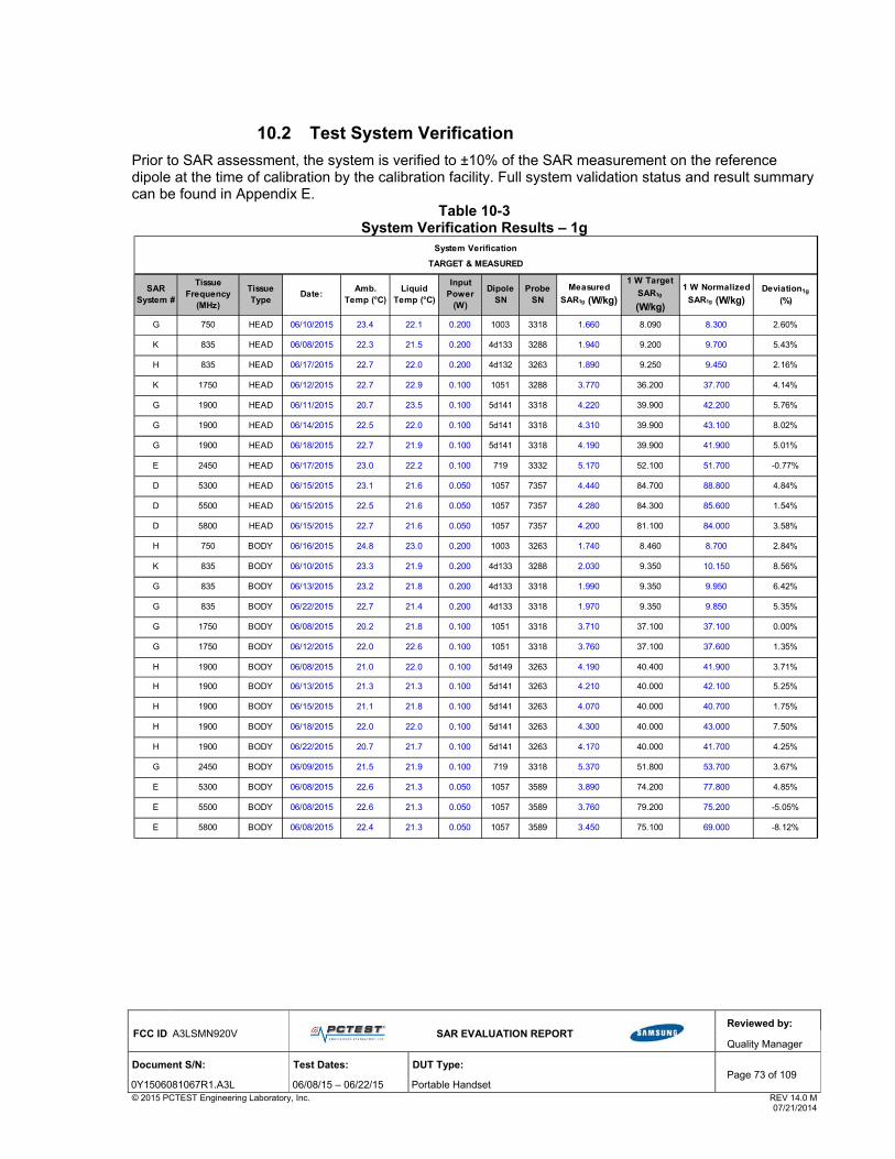
FCC ID: A3LSMN920V
SAR EVALUATION REPORT
Reviewed by:
Quality Manager
Document S/N: Test Dates: DUT Type: Page 73 of 109
0Y1506081067R1.A3L 06/08/15 – 06/22/15 Portable Handset © 2015 PCTEST Engineering Laboratory, Inc. REV 14.0 M 07/21/2014
10.2 Test System Verification
Prior to SAR assessment, the system is verified to ±10% of the SAR measurement on the reference dipole at the time of calibration by the calibration facility. Full system validation status and result summary can be found in Appendix E.
Table 10-3 System Verification Results – 1g
G 750 HEAD 06/10/2015 23.4 22.1 0.200 1003 3318 1.660 8.090 8.300 2.60%
K 835 HEAD 06/08/2015 22.3 21.5 0.200 4d133 3288 1.940 9.200 9.700 5.43%
H 835 HEAD 06/17/2015 22.7 22.0 0.200 4d132 3263 1.890 9.250 9.450 2.16%
K 1750 HEAD 06/12/2015 22.7 22.9 0.100 1051 3288 3.770 36.200 37.700 4.14%
G 1900 HEAD 06/11/2015 20.7 23.5 0.100 5d141 3318 4.220 39.900 42.200 5.76%
G 1900 HEAD 06/14/2015 22.5 22.0 0.100 5d141 3318 4.310 39.900 43.100 8.02%
G 1900 HEAD 06/18/2015 22.7 21.9 0.100 5d141 3318 4.190 39.900 41.900 5.01%
E 2450 HEAD 06/17/2015 23.0 22.2 0.100 719 3332 5.170 52.100 51.700 -0.77%
D 5300 HEAD 06/15/2015 23.1 21.6 0.050 1057 7357 4.440 84.700 88.800 4.84%
D 5500 HEAD 06/15/2015 22.5 21.6 0.050 1057 7357 4.280 84.300 85.600 1.54%
D 5800 HEAD 06/15/2015 22.7 21.6 0.050 1057 7357 4.200 81.100 84.000 3.58%
H 750 BODY 06/16/2015 24.8 23.0 0.200 1003 3263 1.740 8.460 8.700 2.84%
K 835 BODY 06/10/2015 23.3 21.9 0.200 4d133 3288 2.030 9.350 10.150 8.56%
G 835 BODY 06/13/2015 23.2 21.8 0.200 4d133 3318 1.990 9.350 9.950 6.42%
G 835 BODY 06/22/2015 22.7 21.4 0.200 4d133 3318 1.970 9.350 9.850 5.35%
G 1750 BODY 06/08/2015 20.2 21.8 0.100 1051 3318 3.710 37.100 37.100 0.00%
G 1750 BODY 06/12/2015 22.0 22.6 0.100 1051 3318 3.760 37.100 37.600 1.35%
H 1900 BODY 06/08/2015 21.0 22.0 0.100 5d149 3263 4.190 40.400 41.900 3.71%
H 1900 BODY 06/13/2015 21.3 21.3 0.100 5d141 3263 4.210 40.000 42.100 5.25%
H 1900 BODY 06/15/2015 21.1 21.8 0.100 5d141 3263 4.070 40.000 40.700 1.75%
H 1900 BODY 06/18/2015 22.0 22.0 0.100 5d141 3263 4.300 40.000 43.000 7.50%
H 1900 BODY 06/22/2015 20.7 21.7 0.100 5d141 3263 4.170 40.000 41.700 4.25%
G 2450 BODY 06/09/2015 21.5 21.9 0.100 719 3318 5.370 51.800 53.700 3.67%
E 5300 BODY 06/08/2015 22.6 21.3 0.050 1057 3589 3.890 74.200 77.800 4.85%
E 5500 BODY 06/08/2015 22.6 21.3 0.050 1057 3589 3.760 79.200 75.200 -5.05%
E 5800 BODY 06/08/2015 22.4 21.3 0.050 1057 3589 3.450 75.100 69.000 -8.12%
1 W Normalized
SAR1g (W/kg)Dipole
SNTissue Type
Probe SN
Date:Amb.
Temp (°C)Liquid
Temp (°C)
Input Power
(W)
Measured
SAR1g (W/kg)Deviation1g
(%)
1 W Target
SAR1g
(W/kg)
System Verification
TARGET & MEASURED
SAR System #
Tissue Frequency
(MHz)

FCC ID: A3LSMN920V
SAR EVALUATION REPORT
Reviewed by:
Quality Manager
Document S/N: Test Dates: DUT Type: Page 74 of 109
0Y1506081067R1.A3L 06/08/15 – 06/22/15 Portable Handset © 2015 PCTEST Engineering Laboratory, Inc. REV 14.0 M 07/21/2014
Table 10-4 System Verification Results – 10g
Figure 10-1
System Verification Setup Diagram
Figure 10-2
System Verification Setup Photo
G 1750 BODY 06/12/2015 22.0 22.6 0.100 1051 3318 2.000 20.000 20.000 0.00%
H 1900 BODY 06/13/2015 21.3 21.3 0.100 5d141 3263 2.210 21.200 22.100 4.25%
H 1900 BODY 06/18/2015 22.0 22.0 0.100 5d141 3263 2.250 21.200 22.500 6.13%
H 1900 BODY 06/22/2015 20.7 21.7 0.100 5d141 3263 2.180 21.200 21.800 2.83%
E 5300 BODY 06/08/2015 22.6 21.3 0.050 1057 3589 1.090 20.900 21.800 4.31%
E 5500 BODY 06/08/2015 22.6 21.3 0.050 1057 3589 1.050 22.000 21.000 -4.55%
E 5800 BODY 06/08/2015 22.4 21.3 0.050 1057 3589 0.966 20.600 19.320 -6.21%
Input Power
(W)
Dipole SN
Probe SN
Measured
SAR10 g (W/kg)
1 W Target
SAR10 g
(W/kg)
1 W Normalized
SAR10 g (W/kg)
Deviation10g
(%)
System Verification
TARGET & MEASURED
SAR System #
Tissue Frequency
(MHz)
Tissue Type
Date:Amb.
Temp (°C)Liquid
Temp (°C)

FCC ID: A3LSMN920V
SAR EVALUATION REPORT
Reviewed by:
Quality Manager
Document S/N: Test Dates: DUT Type: Page 75 of 109
0Y1506081067R1.A3L 06/08/15 – 06/22/15 Portable Handset © 2015 PCTEST Engineering Laboratory, Inc. REV 14.0 M 07/21/2014
11 S A R D A T A S U M M A R Y
11.1 Standalone Head SAR Data
Table 11-1 GSM 850 Head SAR
Table 11-2 GSM 1900 Head SAR Data
Table 11-3 UMTS 850 Head SAR Data
SAR (1g)Scaled SAR
(1g)
MHz Ch. (W/kg) (W/kg)
836.60 190 GSM 850 GSM 33.5 33.28 0.01 Right Cheek ADDBE 1 1:8.3 0.173 1.052 0.182 A1
836.60 190 GSM 850 GSM 33.5 33.28 0.03 Right Tilt ADDBE 1 1:8.3 0.073 1.052 0.077
836.60 190 GSM 850 GSM 33.5 33.28 -0.03 Left Cheek ADDBE 1 1:8.3 0.117 1.052 0.123
836.60 190 GSM 850 GSM 33.5 33.28 0.02 Left Tilt ADDBE 1 1:8.3 0.067 1.052 0.070
Uncontrolled Exposure/General Population
ANSI / IEEE C95.1 1992 - SAFETY LIMIT
Conducted Power [dBm]
Head
averaged over 1 gram
Spatial Peak 1.6 W/kg (mW/g)
# of Time Slots
Device Serial
Number
FREQUENCYMode/Band
MEASUREMENT RESULTS
Maximum Allowed Power [dBm]
Test Position
Service Plot #Scaling Factor
Power Drift [dB]
Side Duty Cycle
SAR (1g)Scaled SAR
(1g)
MHz Ch. (W/kg) (W/kg)
1880.00 661 GSM 1900 GSM 30.5 29.52 -0.03 Right Cheek ADDBE 1 1:8.3 0.089 1.253 0.112 A2
1880.00 661 GSM 1900 GSM 30.5 29.52 0.03 Right Tilt ADDBE 1 1:8.3 0.053 1.253 0.066
1880.00 661 GSM 1900 GSM 30.5 29.52 0.02 Left Cheek ADDBE 1 1:8.3 0.061 1.253 0.076
1880.00 661 GSM 1900 GSM 30.5 29.52 0.02 Left Tilt ADDBE 1 1:8.3 0.035 1.253 0.044
Maximum Allowed
Power [dBm]
Conducted Power [dBm]
1.6 W/kg (mW/g)
averaged over 1 gram
ANSI / IEEE C95.1 1992 - SAFETY LIMIT
Spatial Peak
Uncontrolled Exposure/General Population
Head
FREQUENCYMode/Band Service
MEASUREMENT RESULTS
# of Time Slots
Duty Cycle
Scaling Factor
Plot #SideTest
Position
Device Serial
Number
Power Drift [dB]
SAR (1g)Scaled SAR
(1g)
MHz Ch. (W/kg) (W/kg)
836.60 4183 UMTS 850 RMC 23.5 22.90 0.03 Right Cheek ADDBE 1:1 0.159 1.148 0.183 A3
836.60 4183 UMTS 850 RMC 23.5 22.90 0.04 Right Tilt ADDBE 1:1 0.071 1.148 0.082
836.60 4183 UMTS 850 RMC 23.5 22.90 0.03 Left Cheek ADDBE 1:1 0.118 1.148 0.135
836.60 4183 UMTS 850 RMC 23.5 22.90 0.04 Left Tilt ADDBE 1:1 0.068 1.148 0.078
Uncontrolled Exposure/General Population averaged over 1 gram
MEASUREMENT RESULTS
Maximum Allowed Power [dBm]
Duty Cycle
Scaling Factor
Plot #
ANSI / IEEE C95.1 1992 - SAFETY LIMIT
Conducted Power [dBm]
Spatial Peak 1.6 W/kg (mW/g)
Head
Device Serial
NumberSide
Power Drift [dB]
ServiceFREQUENCY
Mode/BandTest
Position

FCC ID: A3LSMN920V
SAR EVALUATION REPORT
Reviewed by:
Quality Manager
Document S/N: Test Dates: DUT Type: Page 76 of 109
0Y1506081067R1.A3L 06/08/15 – 06/22/15 Portable Handset © 2015 PCTEST Engineering Laboratory, Inc. REV 14.0 M 07/21/2014
Table 11-4 UMTS 1900 Head SAR Data
Table 11-5 Cell. CDMA Head SAR Data
Table 11-6 PCS CDMA Head SAR Data
SAR (1g)Scaled
SAR (1g)
MHz Ch. (W/kg) (W/kg)
1880.00 9400 UMTS 1900 RMC 23.5 22.73 -0.19 Right Cheek ADDBE 1:1 0.155 1.194 0.185 A4
1880.00 9400 UMTS 1900 RMC 23.5 22.73 0.04 Right Tilt ADDBE 1:1 0.091 1.194 0.109
1880.00 9400 UMTS 1900 RMC 23.5 22.73 0.14 Left Cheek ADDBE 1:1 0.110 1.194 0.131
1880.00 9400 UMTS 1900 RMC 23.5 22.73 0.03 Left Tilt ADDBE 1:1 0.061 1.194 0.073
Spatial Peak 1.6 W/kg (mW/g)
Uncontrolled Exposure/General Population averaged over 1 gram
MEASUREMENT RESULTS
Duty CycleScaling Factor
Plot #
ANSI / IEEE C95.1 1992 - SAFETY LIMIT Head
SideTest
Position
Device Serial
Number
Power Drift [dB]
Maximum Allowed Power [dBm]
Conducted Power [dBm]
FREQUENCYMode/Band Service
SAR (1g)Scaled SAR
(1g)
MHz Ch. (W/kg) (W/kg)
836.52 384 Cell. CDMA RC3 / SO55 25.0 24.52 0.02 Right Cheek AC31E 1:1 0.185 1.117 0.207 A5
836.52 384 Cell. CDMA RC3 / SO55 25.0 24.52 0.07 Right Tilt AC31E 1:1 0.082 1.117 0.092
836.52 384 Cell. CDMA RC3 / SO55 25.0 24.52 0.08 Left Cheek AC31E 1:1 0.133 1.117 0.149
836.52 384 Cell. CDMA RC3 / SO55 25.0 24.52 0.04 Left Tilt AC31E 1:1 0.079 1.117 0.088
836.52 384 Cell. CDMA EVDO Rev. A 25.0 24.47 0.05 Right Cheek AC31E 1:1 0.179 1.130 0.202
836.52 384 Cell. CDMA EVDO Rev. A 25.0 24.47 0.11 Right Tilt AC31E 1:1 0.080 1.130 0.090
836.52 384 Cell. CDMA EVDO Rev. A 25.0 24.47 0.06 Left Cheek AC31E 1:1 0.120 1.130 0.136
836.52 384 Cell. CDMA EVDO Rev. A 25.0 24.47 0.04 Left Tilt AC31E 1:1 0.078 1.130 0.088
1 000 1 000
Uncontrolled Exposure/General Population averaged over 1 gram
MEASUREMENT RESULTS
Duty CycleScaling Factor
Plot #
ANSI / IEEE C95.1 1992 - SAFETY LIMIT
Test Position
Conducted Power [dBm]
Spatial Peak 1.6 W/kg (mW/g)
Head
Maximum Allowed Power [dBm]
Device Serial
NumberService
FREQUENCYMode/Band Side
Power Drift [dB]
SAR (1g)Scaled SAR
(1g)
MHz Ch. (W/kg) (W/kg)
1880.00 600 PCS CDMA RC3 / SO55 25.0 24.55 0.09 Right Cheek AC31E 1:1 0.183 1.109 0.203 A6
1880.00 600 PCS CDMA RC3 / SO55 25.0 24.55 0.03 Right Tilt AC31E 1:1 0.101 1.109 0.112
1880.00 600 PCS CDMA RC3 / SO55 25.0 24.55 -0.08 Left Cheek AC31E 1:1 0.135 1.109 0.150
1880.00 600 PCS CDMA RC3 / SO55 25.0 24.55 0.03 Left Tilt AC31E 1:1 0.069 1.109 0.077
1880.00 600 PCS CDMA EVDO Rev. A 25.0 24.44 -0.03 Right Cheek AC31E 1:1 0.177 1.138 0.201
1880.00 600 PCS CDMA EVDO Rev. A 25.0 24.44 -0.07 Right Tilt AC31E 1:1 0.110 1.138 0.125
1880.00 600 PCS CDMA EVDO Rev. A 25.0 24.44 -0.20 Left Cheek AC31E 1:1 0.140 1.138 0.159
1880.00 600 PCS CDMA EVDO Rev. A 25.0 24.44 -0.02 Left Tilt AC31E 1:1 0.077 1.138 0.088
1880.00 600 PCS CDMA EVDO Rev. A 21.5 21.19 0.03 Right Cheek AD7CE 1:1 0.104 1.074 0.112
1880.00 600 PCS CDMA EVDO Rev. A 21.5 21.19 -0.03 Right Tilt AD7CE 1:1 0.066 1.074 0.071
1880.00 600 PCS CDMA EVDO Rev. A 21.5 21.19 0.17 Left Cheek AD7CE 1:1 0.107 1.074 0.115
1880.00 600 PCS CDMA EVDO Rev. A 21.5 21.19 0.11 Left Tilt AD7CE 1:1 0.044 1.074 0.049
Maximum Allowed Power [dBm]
Conducted Power [dBm]
FREQUENCYMode/Band Service
Spatial Peak 1.6 W/kg (mW/g)
Uncontrolled Exposure/General Population averaged over 1 gram
MEASUREMENT RESULTS
Duty Cycle
Scaling Factor
Plot #
ANSI / IEEE C95.1 1992 - SAFETY LIMIT Head
SideTest
Position
Device Serial
Number
Power Drift [dB]

FCC ID: A3LSMN920V
SAR EVALUATION REPORT
Reviewed by:
Quality Manager
Document S/N: Test Dates: DUT Type: Page 77 of 109
0Y1506081067R1.A3L 06/08/15 – 06/22/15 Portable Handset © 2015 PCTEST Engineering Laboratory, Inc. REV 14.0 M 07/21/2014
Table 11-7
LTE Band 13 Head SAR Data
Table 11-8 LTE Band 5 (Cell) Head SAR Data
Table 11-9 LTE Band 4 (AWS) Head SAR Data
SAR (1g)Scaled
SAR (1g)
MHz (W/kg) (W/kg)
782.00 23230 Mid LTE Band 13 10 24.5 23.96 -0.03 0 Right Cheek QPSK 1 49 AB613 1:1 0.167 1.132 0.189 A7
782.00 23230 Mid LTE Band 13 10 23.5 23.10 0.11 1 Right Cheek QPSK 25 0 AB613 1:1 0.153 1.096 0.168
782.00 23230 Mid LTE Band 13 10 24.5 23.96 -0.15 0 Right Tilt QPSK 1 49 AB613 1:1 0.073 1.132 0.083
782.00 23230 Mid LTE Band 13 10 23.5 23.10 0.11 1 Right Tilt QPSK 25 0 AB613 1:1 0.071 1.096 0.078
782.00 23230 Mid LTE Band 13 10 24.5 23.96 -0.05 0 Left Cheek QPSK 1 49 AB613 1:1 0.112 1.132 0.127
782.00 23230 Mid LTE Band 13 10 23.5 23.10 0.07 1 Left Cheek QPSK 25 0 AB613 1:1 0.103 1.096 0.113
782.00 23230 Mid LTE Band 13 10 24.5 23.96 -0.06 0 Left Tilt QPSK 1 49 AB613 1:1 0.076 1.132 0.086
782.00 23230 Mid LTE Band 13 10 23.5 23.10 -0.15 1 Left Tilt QPSK 25 0 AB613 1:1 0.065 1.096 0.071
Scaling Factor
Plot #
MEASUREMENT RESULTS
Head
1.6 W/kg (mW/g)
Side
averaged over 1 gram
Duty Cycle
ANSI / IEEE C95.1 1992 - SAFETY LIMIT
Spatial Peak
Uncontrolled Exposure/General Population
Modulation RB Size RB OffsetBandwidth
[MHz]Test
Position
Maximum Allowed Power [dBm]
Device Serial
NumberMPR [dB]Mode
Conducted Power [dBm]
Power Drift [dB]
FREQUENCY
Ch.
SAR (1g)Scaled SAR
(1g)
MHz (W/kg) (W/kg)
836.50 20525 Mid LTE Band 5 (Cell) 10 24.5 24.27 0.05 0 Right Cheek QPSK 1 49 AB613 1:1 0.132 1.054 0.139 A8
836.50 20525 Mid LTE Band 5 (Cell) 10 23.5 23.16 0.10 1 Right Cheek QPSK 25 0 AB613 1:1 0.102 1.081 0.110
836.50 20525 Mid LTE Band 5 (Cell) 10 24.5 24.27 0.08 0 Right Tilt QPSK 1 49 AB613 1:1 0.066 1.054 0.070
836.50 20525 Mid LTE Band 5 (Cell) 10 23.5 23.16 0.10 1 Right Tilt QPSK 25 0 AB613 1:1 0.048 1.081 0.052
836.50 20525 Mid LTE Band 5 (Cell) 10 24.5 24.27 0.06 0 Left Cheek QPSK 1 49 AB613 1:1 0.088 1.054 0.093
836.50 20525 Mid LTE Band 5 (Cell) 10 23.5 23.16 -0.03 1 Left Cheek QPSK 25 0 AB613 1:1 0.067 1.081 0.072
836.50 20525 Mid LTE Band 5 (Cell) 10 24.5 24.27 0.05 0 Left Tilt QPSK 1 49 AB613 1:1 0.045 1.054 0.047
836.50 20525 Mid LTE Band 5 (Cell) 10 23.5 23.16 0.16 1 Left Tilt QPSK 25 0 AB613 1:1 0.043 1.081 0.046
2 000 1 000
Uncontrolled Exposure/General Population averaged over 1 gram
Modulation RB Size RB Offset
ANSI / IEEE C95.1 1992 - SAFETY LIMIT Head
Spatial Peak 1.6 W/kg (mW/g)
Device Serial
Number
Power Drift [dB]
ModeConducted
Power [dBm]
FREQUENCY
Ch.
MEASUREMENT RESULTS
Duty CycleScaling Factor
Plot #Bandwidth
[MHz]
Maximum Allowed Power [dBm]
Test Position
MPR [dB] Side
SAR (1g)Scaled SAR
(1g)
MHz (W/kg) (W/kg)
1732.50 20175 Mid LTE Band 4 (AWS) 20 24.5 24.20 0.00 0 Right Cheek QPSK 1 0 AB613 1:1 0.160 1.072 0.172 A9
1732.50 20175 Mid LTE Band 4 (AWS) 20 23.5 23.30 -0.05 1 Right Cheek QPSK 50 0 AB613 1:1 0.158 1.047 0.165
1732.50 20175 Mid LTE Band 4 (AWS) 20 24.5 24.20 0.06 0 Right Tilt QPSK 1 0 AB613 1:1 0.040 1.072 0.043
1732.50 20175 Mid LTE Band 4 (AWS) 20 23.5 23.30 0.14 1 Right Tilt QPSK 50 0 AB613 1:1 0.040 1.047 0.042
1732.50 20175 Mid LTE Band 4 (AWS) 20 24.5 24.20 0.02 0 Left Cheek QPSK 1 0 AB613 1:1 0.146 1.072 0.157
1732.50 20175 Mid LTE Band 4 (AWS) 20 23.5 23.30 0.07 1 Left Cheek QPSK 50 0 AB613 1:1 0.125 1.047 0.131
1732.50 20175 Mid LTE Band 4 (AWS) 20 24.5 24.20 -0.12 0 Left Tilt QPSK 1 0 AB613 1:1 0.050 1.072 0.054
1732.50 20175 Mid LTE Band 4 (AWS) 20 23.5 23.30 0.09 1 Left Tilt QPSK 50 0 AB613 1:1 0.049 1.047 0.051
1 000 2 000
Uncontrolled Exposure/General Population averaged over 1 gram
Duty CycleScaling Factor
Plot #
ANSI / IEEE C95.1 1992 - SAFETY LIMIT Head
Spatial Peak 1.6 W/kg (mW/g)
Test Position
Power Drift [dB]
ModulationMode
Maximum Allowed Power [dBm]
Conducted Power [dBm]
Bandwidth [MHz]
MEASUREMENT RESULTS
Device Serial
NumberRB OffsetMPR [dB] Side RB Size
FREQUENCY
Ch.
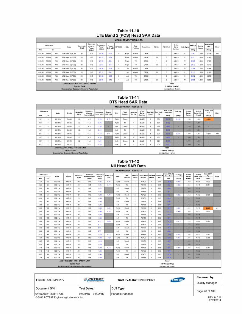
FCC ID: A3LSMN920V
SAR EVALUATION REPORT
Reviewed by:
Quality Manager
Document S/N: Test Dates: DUT Type: Page 78 of 109
0Y1506081067R1.A3L 06/08/15 – 06/22/15 Portable Handset © 2015 PCTEST Engineering Laboratory, Inc. REV 14.0 M 07/21/2014
Table 11-10 LTE Band 2 (PCS) Head SAR Data
Table 11-11 DTS Head SAR Data
Table 11-12 NII Head SAR Data
SAR (1g)Scaled SAR
(1g)
MHz (W/kg) (W/kg)
1880.00 18900 Mid LTE Band 2 (PCS) 20 24.5 24.10 0.03 0 Right Cheek QPSK 1 0 AB613 1:1 0.162 1.096 0.178 A10
1880.00 18900 Mid LTE Band 2 (PCS) 20 23.5 23.13 0.07 1 Right Cheek QPSK 50 0 AB613 1:1 0.131 1.089 0.143
1880.00 18900 Mid LTE Band 2 (PCS) 20 24.5 24.10 -0.04 0 Right Tilt QPSK 1 0 AB613 1:1 0.095 1.096 0.104
1880.00 18900 Mid LTE Band 2 (PCS) 20 23.5 23.13 -0.17 1 Right Tilt QPSK 50 0 AB613 1:1 0.073 1.089 0.079
1880.00 18900 Mid LTE Band 2 (PCS) 20 24.5 24.10 0.04 0 Left Cheek QPSK 1 0 AB613 1:1 0.144 1.096 0.158
1880.00 18900 Mid LTE Band 2 (PCS) 20 23.5 23.13 -0.01 1 Left Cheek QPSK 50 0 AB613 1:1 0.113 1.089 0.123
1880.00 18900 Mid LTE Band 2 (PCS) 20 24.5 24.10 0.07 0 Left Tilt QPSK 1 0 AB613 1:1 0.072 1.096 0.079
1880.00 18900 Mid LTE Band 2 (PCS) 20 23.5 23.13 0.18 1 Left Tilt QPSK 50 0 AB613 1:1 0.055 1.089 0.060
1 000 2 000
Spatial Peak 1.6 W/kg (mW/g)
Uncontrolled Exposure/General Population averaged over 1 gram
Device Serial
NumberDuty Cycle
Scaling Factor
Plot #Pow er
Drift [dB]MPR [dB] Side
ANSI / IEEE C95.1 1992 - SAFETY LIMIT Head
RB Size RB OffsetTest
PositionModulationMode
Maximum Allow ed Pow er [dBm]
Conducted Pow er [dBm]
FREQUENCY
Ch.
Bandwidth [MHz]
MEASUREMENT RESULTS
Peak SAR of Area Scan
SAR (1g)Scaled SAR
(1g)
MHz Ch. W/kg (W/kg) (W/kg)
2437 6 802.11b DSSS 22 14.5 13.95 0.17 Right Cheek 1 ABAEB 1 99.6 0.257 0.203 1.135 1.004 0.231
2437 6 802.11b DSSS 22 14.5 13.95 - Right Tilt 1 ABAEB 1 99.6 0.192 - 1.135 1.004 -
2437 6 802.11b DSSS 22 14.5 13.95 - Left Cheek 1 ABAEB 1 99.6 0.066 - 1.135 1.004 -
2437 6 802.11b DSSS 22 14.5 13.95 - Left Tilt 1 ABAEB 1 99.6 0.052 - 1.135 1.004 -
2437 6 802.11b DSSS 22 14.5 14.50 0.14 Right Cheek 2 ABAEB 1 99.9 0.208 0.219 1.000 1.001 0.219 A11
2437 6 802.11b DSSS 22 14.5 14.50 - Right Tilt 2 ABAEB 1 99.9 0.019 - 1.000 1.001 -
2437 6 802.11b DSSS 22 14.5 14.50 - Left Cheek 2 ABAEB 1 99.9 0.150 - 1.000 1.001 -
2437 6 802.11b DSSS 22 14.5 14.50 - Left Tilt 2 ABAEB 1 99.9 0.130 - 1.000 1.001 -
FREQUENCYMode Side
Conducted Power [dBm]
Service
MEASUREMENT RESULTS
Device Serial
Number
Antenna Config.
Bandwidth [MHz]
averaged over 1 gram
Power Drift [dB]
Maximum Allowed
Power [dBm]
Duty Cycle (%)
Scaling Factor
(Power)Plot #
Uncontrolled Exposure/General Population
Data Rate (Mbps)
ANSI / IEEE C95.1 1992 - SAFETY LIMIT
Test Position
Spatial Peak
Head
1.6 W/kg (mW/g)
Scaling Factor (Duty
Cycle)
Peak SAR of Area Scan
SAR (1g)Scaled SAR
(1g)
MHz Ch. W/kg (W/kg) (W/kg)
5320 64 802.11a OFDM 20 10.5 10.21 0.04 Right Cheek 1 ABAEB 6 98.5 1.010 0.481 1.069 1.015 0.522
5320 64 802.11a OFDM 20 10.5 10.21 0.17 Right Tilt 1 ABAEB 6 98.5 0.651 0.342 1.069 1.015 0.371
5320 64 802.11a OFDM 20 10.5 10.21 - Left Cheek 1 ABAEB 6 98.5 0.350 - 1.069 1.015 -
5320 64 802.11a OFDM 20 10.5 10.21 - Left Tilt 1 ABAEB 6 98.5 0.321 - 1.069 1.015 -
5280 56 802.11a OFDM 20 10.5 10.04 0.09 Right Cheek 2 ABAEB 6 99.8 0.061 0.025 1.112 1.002 0.028
5280 56 802.11a OFDM 20 10.5 10.04 - Right Tilt 2 ABAEB 6 99.8 0.045 - 1.112 1.002 -
5280 56 802.11a OFDM 20 10.5 10.04 - Left Cheek 2 ABAEB 6 99.8 0.008 - 1.112 1.002 -
5280 56 802.11a OFDM 20 10.5 10.04 - Left Tilt 2 ABAEB 6 99.8 0.006 - 1.112 1.002 -
5500 100 802.11a OFDM 20 10.5 10.50 0.03 Right Cheek 1 ABAEB 6 98.5 1.840 0.657 1.000 1.015 0.667 A12
5500 100 802.11a OFDM 20 10.5 10.50 0.16 Right Tilt 1 ABAEB 6 98.5 0.772 0.448 1.000 1.015 0.455
5500 100 802.11a OFDM 20 10.5 10.50 - Left Cheek 1 ABAEB 6 98.5 0.492 - 1.000 1.015 -
5500 100 802.11a OFDM 20 10.5 10.50 - Left Tilt 1 ABAEB 6 98.5 0.390 - 1.000 1.015 -
5500 100 802.11a OFDM 20 10.5 9.77 -0.02 Right Cheek 2 ABAEB 6 99.8 0.218 0.173 1.183 1.002 0.205
5500 100 802.11a OFDM 20 10.5 9.77 - Right Tilt 2 ABAEB 6 99.8 0.215 - 1.183 1.002 -
5500 100 802.11a OFDM 20 10.5 9.77 - Left Cheek 2 ABAEB 6 99.8 0.019 - 1.183 1.002 -
5500 100 802.11a OFDM 20 10.5 9.77 - Left Tilt 2 ABAEB 6 99.8 0.009 - 1.183 1.002 -
5825 165 802.11a OFDM 20 10.5 10.10 0.13 Right Cheek 1 ABAEB 6 98.5 1.160 0.522 1.096 1.015 0.581
5825 165 802.11a OFDM 20 10.5 10.10 -0.07 Right Tilt 1 ABAEB 6 98.5 0.663 0.359 1.096 1.015 0.399
5825 165 802.11a OFDM 20 10.5 10.10 - Left Cheek 1 ABAEB 6 98.5 0.289 - 1.096 1.015 -
5825 165 802.11a OFDM 20 10.5 10.10 - Left Tilt 1 ABAEB 6 98.5 0.327 - 1.096 1.015 -
5745 149 802.11a OFDM 20 10.5 10.49 0.12 Right Cheek 2 ABAEB 6 99.8 0.634 0.285 1.002 1.002 0.287
5745 149 802.11a OFDM 20 10.5 10.49 - Right Tilt 2 ABAEB 6 99.8 0.470 - 1.002 1.002 -
5745 149 802.11a OFDM 20 10.5 10.49 - Left Cheek 2 ABAEB 6 99.8 0.279 - 1.002 1.002 -
5745 149 802.11a OFDM 20 10.5 10.49 - Left Tilt 2 ABAEB 6 99.8 0.240 - 1.002 1.002 -
FREQUENCYMode
MEASUREMENT RESULTS
Duty Cycle (%)
Device Serial Number
Conducted Power [dBm]
Bandwidth [MHz]
Scaling Factor (Duty
Cycle)
Spatial Peak
Uncontrolled Exposure/General Population
Scaling Factor
(Power)Plot #Side
Head
1.6 W/kg (mW/g)
averaged over 1 gram
Maximum Allowed Power
[dBm]
Data Rate (Mbps)
ANSI / IEEE C95.1 1992 - SAFETY LIMIT
Test Position
Power Drift [dB]
Antenna Config.
Service

FCC ID: A3LSMN920V
SAR EVALUATION REPORT
Reviewed by:
Quality Manager
Document S/N: Test Dates: DUT Type: Page 79 of 109
0Y1506081067R1.A3L 06/08/15 – 06/22/15 Portable Handset © 2015 PCTEST Engineering Laboratory, Inc. REV 14.0 M 07/21/2014
11.2 Standalone Body-Worn SAR Data
Table 11-13 GSM/UMTS/CDMA Body-Worn SAR Data
Table 11-14 LTE Body-Worn SAR Data
Table 11-15 DTS Body-Worn SAR Data
Table 11-16 NII Body-Worn SAR Data
SAR (1g)Scaled SAR
(1g)
MHz Ch. (W/kg) (W/kg)
836.60 190 GSM 850 GSM 33.5 33.28 -0.06 15 mm ADDBE 1 1:8.3 back 0.385 1.052 0.405 A13
1 000 A151880.00 661 GSM 1900 GSM 30.5 29.52 0.00 15 mm ADDBE 1 1:8.3 back 0.263 1.253 0.330 A15
1 000 1 000836.60 4183 UMTS 850 RMC 23.5 22.90 -0.01 15 mm ADDBE N/A 1:1 back 0.309 1.148 0.355 A17
1 000 1 0001880.00 9400 UMTS 1900 RMC 23.5 22.73 0.00 15 mm ADDBE N/A 1:1 back 0.461 1.194 0.550 A19
1 000 1 000836.52 384 Cell. CDMA TDSO / SO32 25.0 24.63 0.03 15 mm AC31E N/A 1:1 back 0.450 1.089 0.490 A21
1 000 1 0001880.00 600 PCS CDMA TDSO / SO32 25.0 24.63 0.03 15 mm AC31E N/A 1:1 back 0.645 1.089 0.702 A23
1 000 1 000
MEASUREMENT RESULTS
Service Side# of Time
SlotsScaling Factor
Plot #Duty Cycle
Spatial Peak
Uncontrolled Exposure/General Population
Power Drift [dB]
Device Serial Number
ModeMaximum Allowed
Power [dBm]
1.6 W/kg (mW/g)
Conducted Power [dBm]
averaged over 1 gram
ANSI / IEEE C95.1 1992 - SAFETY LIMIT
Spacing
Body
FREQUENCY
SAR (1g)Scaled
SAR (1g)
MHz (W/kg) (W/kg)
782.00 23230 Mid LTE Band 13 10 24.5 23.96 0.11 0 AB613 QPSK 1 49 15 mm back 1:1 0.381 1.132 0.431 A25
782.00 23230 Mid LTE Band 13 10 23.5 23.10 0.01 1 AB613 QPSK 25 0 15 mm back 1:1 0.304 1.096 0.333
#N/A Hi h 2 000 2 000836.50 20525 Mid LTE Band 5 (Cell) 10 24.5 24.27 -0.01 0 AB613 QPSK 1 49 15 mm back 1:1 0.327 1.054 0.345 A27
836.50 20525 Mid LTE Band 5 (Cell) 10 23.5 23.16 0.02 1 AB613 QPSK 25 0 15 mm back 1:1 0.257 1.081 0.278
#N/A Hi h 2 000 2 0001732.50 20175 Mid LTE Band 4 (AWS) 20 24.5 24.20 -0.08 0 AB613 QPSK 1 0 15 mm back 1:1 0.392 1.072 0.420 A29
1732.50 20175 Mid LTE Band 4 (AWS) 20 23.5 23.30 -0.02 1 AB613 QPSK 50 0 15 mm back 1:1 0.315 1.047 0.330
#N/A Hi h 2 000 2 0001880.00 18900 Mid LTE Band 2 (PCS) 20 24.5 24.10 0.00 0 AB613 QPSK 1 0 15 mm back 1:1 0.535 1.096 0.586 A31
1880.00 18900 Mid LTE Band 2 (PCS) 20 23.5 23.13 0.02 1 AB613 QPSK 50 0 15 mm back 1:1 0.389 1.089 0.424
2 000 2 000
FREQUENCY
Spatial Peak
ANSI / IEEE C95.1 1992 - SAFETY LIMIT
MEASUREMENT RESULTS
Duty Cycle
Scaling Factor
Plot #Pow er
Drift [dB]Side
Maximum Allowed Power
[dBm]
Uncontrolled Exposure/General Population averaged over 1 gram
MPR [dB]
Ch.
RB Size RB OffsetDevice Serial
NumberBandwidth
[MHz]Modulation Spacing
Body
1.6 W/kg (mW/g)
ModeConducted
Power [dBm]
Peak SAR of Area Scan
SAR (1g)Scaled SAR
(1g)
MHz Ch. W/kg (W/kg) (W/kg)
2437 6 802.11b DSSS 22 18.5 18.08 0.02 10 mm 1 ABAEB 1 back 99.6 0.145 0.111 1.102 1.004 0.122
2437 6 802.11b DSSS 22 18.5 18.29 0.10 10 mm 2 ABAEB 1 back 99.9 0.145 0.114 1.050 1.001 0.120 A33
IEEE 802 11b 1 000 1 000 1 0002 000 1 000
1.6 W/kg (mW/g)
averaged over 1 gram
Spatial Peak
Uncontrolled Exposure/General Population
SideDuty Cycle
(%)
Scaling Factor
(Power)Plot #
ANSI / IEEE C95.1 1992 - SAFETY LIMIT Body
MEASUREMENT RESULTS
FREQUENCYMode Service
Maximum Allow ed Power [dBm]
Conducted Power [dBm]
SpacingAntenna Config.
Pow er Drift [dB]
Data Rate (Mbps)
Device Serial
Number
Scaling Factor (Duty Cycle)
Bandw idth [MHz]
Peak SAR of Area Scan
SAR (1g)Scaled SAR
(1g)
MHz Ch. W/kg (W/kg) (W/kg)
5300 60 802.11a OFDM 20 15.5 15.04 -0.05 10 mm 1 ABAEB 6 back 98.5 0.316 0.114 1.112 1.015 0.129
5260 52 802.11a OFDM 20 15.5 15.33 -0.14 10 mm 2 ABAEB 6 back 99.8 0.169 0.088 1.040 1.002 0.092
5720 144 802.11a OFDM 20 15.5 15.18 0.10 10 mm 1 ABAEB 6 back 98.5 0.503 0.235 1.076 1.015 0.257
5500 100 802.11a OFDM 20 15.5 15.15 0.05 10 mm 2 ABAEB 6 back 99.8 0.217 0.093 1.084 1.002 0.101
5745 149 802.11a OFDM 20 15.5 15.48 0.03 10 mm 1 ABAEB 6 back 98.5 0.501 0.256 1.005 1.015 0.261 A34
5745 149 802.11a OFDM 20 15.5 14.83 0.05 10 mm 2 ABAEB 6 back 99.8 0.156 0.077 1.167 1.002 0.090
ANSI / IEEE C95.1 1992 - SAFETY LIMIT
Spatial Peak
Uncontrolled Exposure/General Population
Spacing
Body
1.6 W/kg (mW/g)
averaged over 1 gram
Scaling Factor (Power)
Conducted Pow er [dBm]
Plot #Bandwidth
[MHz]
FREQUENCYMode Service
Maximum Allowed
Pow er [dBm]
MEASUREMENT RESULTS
Antenna Config.
Device Serial Number
Duty Cycle (%)Power Drift
[dB]Data Rate
(Mbps)Side
Scaling Factor (Duty Cycle)

FCC ID: A3LSMN920V
SAR EVALUATION REPORT
Reviewed by:
Quality Manager
Document S/N: Test Dates: DUT Type: Page 80 of 109
0Y1506081067R1.A3L 06/08/15 – 06/22/15 Portable Handset © 2015 PCTEST Engineering Laboratory, Inc. REV 14.0 M 07/21/2014
11.3 Standalone Wireless Router SAR Data
Table 11-17 GPRS/UMTS Hotspot SAR Data
Note: Blue entries represent variability measurements
SAR (1g)Scaled
SAR (1g)
MHz Ch. (W/kg) (W/kg)
824.20 128 GSM 850 GPRS 30.0 29.83 -0.06 10 mm ADDBE 4 1:2.076 back 0.794 1.040 0.826
836.60 190 GSM 850 GPRS 30.0 29.42 -0.10 10 mm ADDBE 4 1:2.076 back 0.876 1.143 1.001
848.80 251 GSM 850 GPRS 30.0 29.63 -0.19 10 mm ADDBE 4 1:2.076 back 0.618 1.089 0.673
824.20 128 GSM 850 GPRS 30.0 29.83 0.04 10 mm ADDBE 4 1:2.076 front 0.892 1.040 0.928 A14
836.60 190 GSM 850 GPRS 30.0 29.42 -0.06 10 mm ADDBE 4 1:2.076 front 0.837 1.143 0.957
848.80 251 GSM 850 GPRS 30.0 29.63 0.02 10 mm ADDBE 4 1:2.076 front 0.701 1.089 0.763
836.60 190 GSM 850 GPRS 30.0 29.42 0.01 10 mm ADDBE 4 1:2.076 bottom 0.417 1.143 0.477
836.60 190 GSM 850 GPRS 30.0 29.42 -0.09 10 mm ADDBE 4 1:2.076 right 0.050 1.143 0.057
836.60 190 GSM 850 GPRS 30.0 29.42 -0.04 10 mm ADDBE 4 1:2.076 left 0.092 1.143 0.105
824.20 128 GSM 850 GPRS 30.0 29.83 -0.05 10 mm ADDBE 4 1:2.076 front 0.840 1.040 0.874
2 000 2 0001909.80 810 GSM 1900 GPRS 24.0 23.93 -0.06 10 mm ADFB5 4 1:2.076 back 0.560 1.016 0.569
1909.80 810 GSM 1900 GPRS 24.0 23.93 -0.04 10 mm ADFB5 4 1:2.076 front 0.653 1.016 0.663
1850.20 512 GSM 1900 GPRS 24.0 23.89 -0.04 10 mm ADFB5 4 1:2.076 bottom 0.664 1.026 0.681
1880.00 661 GSM 1900 GPRS 24.0 23.42 -0.05 10 mm ADFB5 4 1:2.076 bottom 0.816 1.143 0.933
1909.80 810 GSM 1900 GPRS 24.0 23.93 0.01 10 mm ADFB5 4 1:2.076 bottom 1.050 1.016 1.067
1909.80 810 GSM 1900 GPRS 24.0 23.93 0.02 10 mm ADFB5 4 1:2.076 right 0.050 1.016 0.051
1909.80 810 GSM 1900 GPRS 24.0 23.93 -0.01 10 mm ADFB5 4 1:2.076 left 0.186 1.016 0.189
1909.80 810 GSM 1900 GPRS 24.0 23.93 -0.06 10 mm ADFB5 4 1:2.076 bottom 1.060 1.016 1.077 A16
2 000 2 000836.60 4183 UMTS 850 RMC 23.5 22.90 -0.04 10 mm ADDBE N/A 1:1 back 0.515 1.148 0.591 A18
836.60 4183 UMTS 850 RMC 23.5 22.90 -0.01 10 mm ADDBE N/A 1:1 front 0.494 1.148 0.567
836.60 4183 UMTS 850 RMC 23.5 22.90 0.03 10 mm ADDBE N/A 1:1 bottom 0.324 1.148 0.372
836.60 4183 UMTS 850 RMC 23.5 22.90 -0.09 10 mm ADDBE N/A 1:1 right 0.278 1.148 0.319
836.60 4183 UMTS 850 RMC 23.5 22.90 -0.01 10 mm ADDBE N/A 1:1 left 0.079 1.148 0.091
2 000 2 0001880.00 9400 UMTS 1900 RMC 21.0 20.89 -0.01 10 mm ADFB5 N/A 1:1 back 0.671 1.026 0.688
1852.40 9262 UMTS 1900 RMC 21.0 20.80 0.00 10 mm ADFB5 N/A 1:1 front 0.782 1.047 0.819
1880.00 9400 UMTS 1900 RMC 21.0 20.89 0.01 10 mm ADFB5 N/A 1:1 front 0.797 1.026 0.818
1907.60 9538 UMTS 1900 RMC 21.0 20.91 0.02 10 mm ADFB5 N/A 1:1 front 0.744 1.021 0.760
1852.40 9262 UMTS 1900 RMC 21.0 20.80 -0.02 10 mm ADFB5 N/A 1:1 bottom 0.852 1.047 0.892
1880.00 9400 UMTS 1900 RMC 21.0 20.89 -0.03 10 mm ADFB5 N/A 1:1 bottom 0.985 1.026 1.011
1907.60 9538 UMTS 1900 RMC 21.0 20.91 -0.03 10 mm ADFB5 N/A 1:1 bottom 1.030 1.021 1.052 A20
1880.00 9400 UMTS 1900 RMC 21.0 20.89 -0.02 10 mm ADFB5 N/A 1:1 right 0.127 1.026 0.130
1880.00 9400 UMTS 1900 RMC 21.0 20.89 0.01 10 mm ADFB5 N/A 1:1 left 0.144 1.026 0.148
2 000 2 000
Maximum Allowed
Power [dBm]
Device Serial Number
# of GPRS Slots
FREQUENCYMode Service
Conducted Power [dBm]
averaged over 1 gram
Scaling Factor
Plot #
MEASUREMENT RESULTS
Duty Cycle
Body
1.6 W/kg (mW/g)
Power Drift [dB]
Side
ANSI / IEEE C95.1 1992 - SAFETY LIMIT
Spatial Peak
Uncontrolled Exposure/General Population
Spacing

FCC ID: A3LSMN920V
SAR EVALUATION REPORT
Reviewed by:
Quality Manager
Document S/N: Test Dates: DUT Type: Page 81 of 109
0Y1506081067R1.A3L 06/08/15 – 06/22/15 Portable Handset © 2015 PCTEST Engineering Laboratory, Inc. REV 14.0 M 07/21/2014
Table 11-18 CDMA Hotspot SAR Data
Table 11-19 LTE Band 13 Hotspot SAR Data
SAR (1g)Scaled
SAR (1g)
MHz Ch. (W/kg) (W/kg)
824.70 1013 Cell. CDMA EVDO Rev. 0 25.0 24.51 -0.02 10 mm AC31E 1:1 back 0.765 1.119 0.856
836.52 384 Cell. CDMA EVDO Rev. 0 25.0 24.55 -0.03 10 mm AC31E 1:1 back 0.787 1.109 0.873
848.31 777 Cell. CDMA EVDO Rev. 0 25.0 24.54 -0.04 10 mm AC31E 1:1 back 0.758 1.112 0.843
824.70 1013 Cell. CDMA EVDO Rev. 0 25.0 24.51 -0.03 10 mm AC31E 1:1 front 0.852 1.119 0.953
836.52 384 Cell. CDMA EVDO Rev. 0 25.0 24.55 -0.04 10 mm AC31E 1:1 front 0.875 1.109 0.970 A22
848.31 777 Cell. CDMA EVDO Rev. 0 25.0 24.54 0.00 10 mm AC31E 1:1 front 0.848 1.112 0.943
836.52 384 Cell. CDMA EVDO Rev. 0 25.0 24.55 -0.03 10 mm AC31E 1:1 bottom 0.519 1.109 0.576
836.52 384 Cell. CDMA EVDO Rev. 0 25.0 24.55 0.05 10 mm AC31E 1:1 right 0.329 1.109 0.365
836.52 384 Cell. CDMA EVDO Rev. 0 25.0 24.55 -0.01 10 mm AC31E 1:1 left 0.095 1.109 0.105
1880.00 600 PCS CDMA EVDO Rev. 0 21.5 21.21 -0.01 10 mm AD7CE 1:1 back 0.445 1.069 0.476
1880.00 600 PCS CDMA EVDO Rev. 0 21.5 21.21 -0.01 10 mm AD7CE 1:1 front 0.472 1.069 0.505
1851.25 25 PCS CDMA EVDO Rev. 0 21.5 21.19 -0.02 10 mm AD7CE 1:1 bottom 0.920 1.074 0.988
1880.00 600 PCS CDMA EVDO Rev. 0 21.5 21.21 -0.01 10 mm AD7CE 1:1 bottom 0.929 1.069 0.993
1908.75 1175 PCS CDMA EVDO Rev. 0 21.5 21.37 0.01 10 mm AD7CE 1:1 bottom 0.934 1.030 0.962 A24
1880.00 600 PCS CDMA EVDO Rev. 0 21.5 21.21 -0.01 10 mm AD7CE 1:1 right 0.072 1.069 0.077
1880.00 600 PCS CDMA EVDO Rev. 0 21.5 21.21 -0.01 10 mm AD7CE 1:1 left 0.134 1.069 0.143
ANSI / IEEE C95.1 1992 - SAFETY LIMIT Body
Spatial Peak 1.6 W/kg (mW/g)
Uncontrolled Exposure/General Population averaged over 1 gram
Duty Cycle
SideScaling Factor
Plot #SpacingDevice Serial
Number
MEASUREMENT RESULTS
FREQUENCYMode Service
Maximum Allowed
Power [dBm]
Conducted Power [dBm]
Pow er Drift [dB]
SAR (1g)Scaled SAR
(1g)
MHz (W/kg) (W/kg)
782.00 23230 Mid LTE Band 13 10 24.5 23.96 -0.08 0 AB613 QPSK 1 49 10 mm back 1:1 0.582 1.132 0.659
782.00 23230 Mid LTE Band 13 10 23.5 23.10 -0.04 1 AB613 QPSK 25 0 10 mm back 1:1 0.454 1.096 0.498
782.00 23230 Mid LTE Band 13 10 24.5 23.96 -0.09 0 AB613 QPSK 1 49 10 mm front 1:1 0.623 1.132 0.705 A26
782.00 23230 Mid LTE Band 13 10 23.5 23.10 0.00 1 AB613 QPSK 25 0 10 mm front 1:1 0.483 1.096 0.529
782.00 23230 Mid LTE Band 13 10 24.5 23.96 -0.07 0 AB613 QPSK 1 49 10 mm bottom 1:1 0.353 1.132 0.400
782.00 23230 Mid LTE Band 13 10 23.5 23.10 0.02 1 AB613 QPSK 25 0 10 mm bottom 1:1 0.276 1.096 0.302
782.00 23230 Mid LTE Band 13 10 24.5 23.96 0.03 0 AB613 QPSK 1 49 10 mm right 1:1 0.238 1.132 0.269
782.00 23230 Mid LTE Band 13 10 23.5 23.10 0.00 1 AB613 QPSK 25 0 10 mm right 1:1 0.204 1.096 0.224
782.00 23230 Mid LTE Band 13 10 24.5 23.96 -0.09 0 AB613 QPSK 1 49 10 mm left 1:1 0.159 1.132 0.180
782.00 23230 Mid LTE Band 13 10 23.5 23.10 -0.05 1 AB613 QPSK 25 0 10 mm left 1:1 0.147 1.096 0.161
2 000 2 000
MEASUREMENT RESULTS
Body
Power Drift [dB]
Mode SpacingScaling Factor
Plot #Maximum Allowed
Power [dBm]RB Offset
Ch.
Modulation RB SizeConducted
Power [dBm]
Bandwidth [MHz]
averaged over 1 gram
Device Serial Number
MPR [dB]
Spatial Peak
Side
Uncontrolled Exposure/General Population
Duty CycleFREQUENCY
ANSI / IEEE C95.1 1992 - SAFETY LIMIT
1.6 W/kg (mW/g)

FCC ID: A3LSMN920V
SAR EVALUATION REPORT
Reviewed by:
Quality Manager
Document S/N: Test Dates: DUT Type: Page 82 of 109
0Y1506081067R1.A3L 06/08/15 – 06/22/15 Portable Handset © 2015 PCTEST Engineering Laboratory, Inc. REV 14.0 M 07/21/2014
Table 11-20 LTE Band 5 (Cell) Hotspot SAR Data
Table 11-21 LTE Band 4 (AWS) Hotspot SAR Data
Note: Blue entry represents variability measurement
Table 11-22 LTE Band 2 (PCS) Hotspot SAR Data
SAR (1g)Scaled SAR
(1g)
MHz (W/kg) (W/kg)
836.50 20525 Mid LTE Band 5 (Cell) 10 24.5 24.27 0.00 0 AB613 QPSK 1 49 10 mm back 1:1 0.561 1.054 0.591
836.50 20525 Mid LTE Band 5 (Cell) 10 23.5 23.16 -0.06 1 AB613 QPSK 25 0 10 mm back 1:1 0.421 1.081 0.455
836.50 20525 Mid LTE Band 5 (Cell) 10 24.5 24.27 0.05 0 AB613 QPSK 1 49 10 mm front 1:1 0.616 1.054 0.649 A28
836.50 20525 Mid LTE Band 5 (Cell) 10 23.5 23.16 0.03 1 AB613 QPSK 25 0 10 mm front 1:1 0.454 1.081 0.491
836.50 20525 Mid LTE Band 5 (Cell) 10 24.5 24.27 -0.06 0 AB613 QPSK 1 49 10 mm bottom 1:1 0.296 1.054 0.312
836.50 20525 Mid LTE Band 5 (Cell) 10 23.5 23.16 -0.07 1 AB613 QPSK 25 0 10 mm bottom 1:1 0.231 1.081 0.250
836.50 20525 Mid LTE Band 5 (Cell) 10 24.5 24.27 0.11 0 AB613 QPSK 1 49 10 mm right 1:1 0.233 1.054 0.246
836.50 20525 Mid LTE Band 5 (Cell) 10 23.5 23.16 -0.03 1 AB613 QPSK 25 0 10 mm right 1:1 0.183 1.081 0.198
836.50 20525 Mid LTE Band 5 (Cell) 10 24.5 24.27 -0.05 0 AB613 QPSK 1 49 10 mm left 1:1 0.076 1.054 0.080
836.50 20525 Mid LTE Band 5 (Cell) 10 23.5 23.16 -0.06 1 AB613 QPSK 25 0 10 mm left 1:1 0.068 1.081 0.074
Bandwidth [MHz]
SpacingRB OffsetMaximum
Allowed Power [dBm]
MPR [dB] SideDevice Serial
NumberModulation RB Size
MEASUREMENT RESULTS
Uncontrolled Exposure/General Population
FREQUENCY
Ch.
ANSI / IEEE C95.1 1992 - SAFETY LIMIT
Power Drift [dB]
Spatial Peak
Body
1.6 W/kg (mW/g)
averaged over 1 gram
ModeConducted
Power [dBm]
Duty CycleScaling Factor
Plot #
SAR (1g)Scaled SAR
(1g)
MHz (W/kg) (W/kg)
1732.50 20175 Mid LTE Band 4 (AWS) 20 22.5 22.14 -0.08 0 AC258 QPSK 1 0 10 mm back 1:1 0.735 1.086 0.798
1732.50 20175 Mid LTE Band 4 (AWS) 20 22.5 21.90 0.01 0 AC258 QPSK 50 25 10 mm back 1:1 0.602 1.148 0.691
1732.50 20175 Mid LTE Band 4 (AWS) 20 22.5 22.14 -0.03 0 AC258 QPSK 1 0 10 mm front 1:1 0.680 1.086 0.738
1732.50 20175 Mid LTE Band 4 (AWS) 20 22.5 21.90 -0.03 0 AC258 QPSK 50 25 10 mm front 1:1 0.687 1.148 0.789
1732.50 20175 Mid LTE Band 4 (AWS) 20 22.5 22.14 -0.04 0 AC258 QPSK 1 0 10 mm bottom 1:1 0.842 1.086 0.914
1732.50 20175 Mid LTE Band 4 (AWS) 20 22.5 21.90 0.02 0 AC258 QPSK 50 25 10 mm bottom 1:1 0.881 1.148 1.011
1732.50 20175 Mid LTE Band 4 (AWS) 20 22.5 21.89 0.00 0 AC258 QPSK 100 0 10 mm bottom 1:1 0.898 1.151 1.034 A30
1732.50 20175 Mid LTE Band 4 (AWS) 20 22.5 22.14 0.08 0 AC258 QPSK 1 0 10 mm right 1:1 0.116 1.086 0.126
1732.50 20175 Mid LTE Band 4 (AWS) 20 22.5 21.90 -0.02 0 AC258 QPSK 50 25 10 mm right 1:1 0.106 1.148 0.122
1732.50 20175 Mid LTE Band 4 (AWS) 20 22.5 22.14 -0.06 0 AC258 QPSK 1 0 10 mm left 1:1 0.246 1.086 0.267
1732.50 20175 Mid LTE Band 4 (AWS) 20 22.5 21.90 -0.03 0 AC258 QPSK 50 25 10 mm left 1:1 0.252 1.148 0.289
1732.50 20175 Mid LTE Band 4 (AWS) 20 22.5 21.89 -0.01 0 AC258 QPSK 100 0 10 mm bottom 1:1 0.835 1.151 0.961
averaged over 1 gramUncontrolled Exposure/General Population
RB SizeBandwidth
[MHz]Mode
Conducted Power [dBm]
Power Drift [dB]
MPR [dB] SpacingMaximum
Allowed Power [dBm]
RB Offset SideModulationDevice Serial
Number
MEASUREMENT RESULTS
Spatial Peak
ANSI / IEEE C95.1 1992 - SAFETY LIMIT
FREQUENCY
Ch.
Duty CycleScaling Factor
Plot #
Body
1.6 W/kg (mW/g)
SAR (1g)Scaled SAR
(1g)
MHz (W/kg) (W/kg)
1900.00 19100 High LTE Band 2 (PCS) 20 21.0 20.78 -0.05 0 AD7CE QPSK 1 0 10 mm back 1:1 0.419 1.052 0.441
1900.00 19100 High LTE Band 2 (PCS) 20 21.0 20.61 -0.02 0 AD7CE QPSK 50 0 10 mm back 1:1 0.395 1.094 0.432
1900.00 19100 High LTE Band 2 (PCS) 20 21.0 20.78 -0.01 0 AD7CE QPSK 1 0 10 mm front 1:1 0.420 1.052 0.442
1900.00 19100 High LTE Band 2 (PCS) 20 21.0 20.61 0.02 0 AD7CE QPSK 50 0 10 mm front 1:1 0.406 1.094 0.444
1860.00 18700 Low LTE Band 2 (PCS) 20 21.0 20.69 0.05 0 AD7CE QPSK 1 0 10 mm bottom 1:1 0.958 1.074 1.029
1880.00 18900 Mid LTE Band 2 (PCS) 20 21.0 20.75 -0.02 0 AD7CE QPSK 1 0 10 mm bottom 1:1 1.030 1.059 1.091 A32
1900.00 19100 High LTE Band 2 (PCS) 20 21.0 20.78 0.00 0 AD7CE QPSK 1 0 10 mm bottom 1:1 1.010 1.052 1.063
1860.00 18700 Low LTE Band 2 (PCS) 20 21.0 20.60 0.02 0 AD7CE QPSK 50 0 10 mm bottom 1:1 0.966 1.096 1.059
1880.00 18900 Mid LTE Band 2 (PCS) 20 21.0 20.60 -0.02 0 AD7CE QPSK 50 0 10 mm bottom 1:1 1.000 1.096 1.096
1900.00 19100 High LTE Band 2 (PCS) 20 21.0 20.61 -0.02 0 AD7CE QPSK 50 0 10 mm bottom 1:1 0.964 1.094 1.055
1880.00 18900 Mid LTE Band 2 (PCS) 20 21.0 20.58 0.01 0 AD7CE QPSK 100 0 10 mm bottom 1:1 0.987 1.102 1.088
1900.00 19100 High LTE Band 2 (PCS) 20 21.0 20.78 0.02 0 AD7CE QPSK 1 0 10 mm right 1:1 0.069 1.052 0.073
1900.00 19100 High LTE Band 2 (PCS) 20 21.0 20.61 -0.10 0 AD7CE QPSK 50 0 10 mm right 1:1 0.062 1.094 0.068
1900.00 19100 High LTE Band 2 (PCS) 20 21.0 20.78 -0.01 0 AD7CE QPSK 1 0 10 mm left 1:1 0.130 1.052 0.137
1900.00 19100 High LTE Band 2 (PCS) 20 21.0 20.61 0.00 0 AD7CE QPSK 50 0 10 mm left 1:1 0.128 1.094 0.140
2 000 2 000ANSI / IEEE C95.1 1992 - SAFETY LIMIT
RB OffsetModeConducted
Pow er [dBm]Power
Drift [dB]MPR [dB]
Device Serial Number
Bandwidth [MHz]
Modulation
Body
1.6 W/kg (mW/g)
averaged over 1 gram
MEASUREMENT RESULTS
SideMaximum
Allow ed Power [dBm]
Duty CycleScaling Factor
Plot #
Ch.
Spacing
Spatial Peak
Uncontrolled Exposure/General Population
RB SizeFREQUENCY

FCC ID: A3LSMN920V
SAR EVALUATION REPORT
Reviewed by:
Quality Manager
Document S/N: Test Dates: DUT Type: Page 83 of 109
0Y1506081067R1.A3L 06/08/15 – 06/22/15 Portable Handset © 2015 PCTEST Engineering Laboratory, Inc. REV 14.0 M 07/21/2014
Table 11-23 WLAN Hotspot SAR Data
Peak SAR of Area Scan
SAR (1g)Scaled SAR
(1g)
MHz Ch. W/kg (W/kg) (W/kg)
2437 6 802.11b DSSS 22 18.5 18.08 0.02 10 mm 1 ABAEB 1 back 99.6 0.145 0.111 1.102 1.004 0.122
2437 6 802.11b DSSS 22 18.5 18.08 - 10 mm 1 ABAEB 1 front 99.6 0.109 - 1.102 1.004 -
2437 6 802.11b DSSS 22 18.5 18.08 - 10 mm 1 ABAEB 1 top 99.6 0.034 - 1.102 1.004 -
2437 6 802.11b DSSS 22 18.5 18.08 - 10 mm 1 ABAEB 1 left 99.6 0.078 - 1.102 1.004 -
2437 6 802.11b DSSS 22 18.5 18.29 0.10 10 mm 2 ABAEB 1 back 99.9 0.145 0.114 1.050 1.001 0.120 A33
2437 6 802.11b DSSS 22 18.5 18.29 - 10 mm 2 ABAEB 1 front 99.9 0.012 - 1.050 1.001 -
2437 6 802.11b DSSS 22 18.5 18.29 - 10 mm 2 ABAEB 1 top 99.9 0.030 - 1.050 1.001 -
2437 6 802.11b DSSS 22 18.5 18.29 - 10 mm 2 ABAEB 1 left 99.9 0.005 - 1.050 1.001 -
5745 149 802.11a OFDM 20 15.5 15.48 0.03 10 mm 1 ABAEB 6 back 98.5 0.501 0.256 1.005 1.015 0.261 A34
5745 149 802.11a OFDM 20 15.5 15.48 - 10 mm 1 ABAEB 6 front 98.5 0.240 - 1.005 1.015 -
5745 149 802.11a OFDM 20 15.5 15.48 - 10 mm 1 ABAEB 6 top 98.5 0.079 - 1.005 1.015 -
5745 149 802.11a OFDM 20 15.5 15.48 - 10 mm 1 ABAEB 6 left 98.5 0.107 - 1.005 1.015 -
5745 149 802.11a OFDM 20 15.5 14.83 - 10 mm 2 ABAEB 6 back 99.8 0.156 - 1.167 1.002 -
5745 149 802.11a OFDM 20 15.5 14.83 0.03 10 mm 2 ABAEB 6 front 99.8 0.199 0.081 1.167 1.002 0.095
5745 149 802.11a OFDM 20 15.5 14.83 - 10 mm 2 ABAEB 6 top 99.8 0.167 - 1.167 1.002 -
5745 149 802.11a OFDM 20 15.5 14.83 - 10 mm 2 ABAEB 6 left 99.8 0.043 - 1.167 1.002 -
FREQUENCY Conducted Power [dBm]
Mode
MEASUREMENT RESULTS
Antenna Config.
ServiceMaximum Allowed
Power [dBm]
1.6 W/kg (mW/g)
averaged over 1 gram
Data Rate (Mbps)
Power Drift [dB]
Device Serial
NumberSideSpacing
Duty Cycle
(%)
Scaling Factor (Power)
Uncontrolled Exposure/General Population
Plot #
ANSI / IEEE C95.1 1992 - SAFETY LIMIT
Spatial Peak
Body
Scaling Factor (Duty Cycle)
Bandwidth [MHz]

FCC ID: A3LSMN920V
SAR EVALUATION REPORT
Reviewed by:
Quality Manager
Document S/N: Test Dates: DUT Type: Page 84 of 109
0Y1506081067R1.A3L 06/08/15 – 06/22/15 Portable Handset © 2015 PCTEST Engineering Laboratory, Inc. REV 14.0 M 07/21/2014
11.4 Standalone Extremity SAR Data Table 11-24
GPRS/UMTS/CDMA Extremity SAR
Note: Blue entry represents variability measurement
SAR (10g)Scaled
SAR (10g)
MHz Ch. (W/kg) (W/kg)
1880.00 661 GSM 1900 GPRS 28.0 27.41 -0.10 4 mm ADDBE 3 1:2.76 back 1.260 1.146 1.444
1880.00 661 GSM 1900 GPRS 28.0 27.41 -0.02 3 mm ADDBE 3 1:2.76 front 1.620 1.146 1.857
1850.20 512 GSM 1900 GPRS 28.0 27.42 0.01 5 mm ADDBE 3 1:2.76 bottom 1.590 1.143 1.817
1880.00 661 GSM 1900 GPRS 28.0 27.41 0.06 5 mm ADDBE 3 1:2.76 bottom 1.930 1.146 2.212
1909.80 810 GSM 1900 GPRS 28.0 27.50 0.01 5 mm ADDBE 3 1:2.76 bottom 2.050 1.122 2.300 A35
1880.00 661 GSM 1900 GPRS 28.0 27.41 -0.14 0 mm ADDBE 3 1:2.76 right 0.389 1.146 0.446
1880.00 661 GSM 1900 GPRS 28.0 27.41 -0.03 0 mm ADDBE 3 1:2.76 left 0.519 1.146 0.595
1909.80 810 GSM 1900 GPRS 24.0 23.93 0.02 0 mm ADFB5 4 1:2.076 back 1.430 1.016 1.453
1909.80 810 GSM 1900 GPRS 24.0 23.93 0.04 0 mm ADFB5 4 1:2.076 front 1.330 1.016 1.351
1909.80 810 GSM 1900 GPRS 24.0 23.93 0.08 0 mm ADFB5 4 1:2.076 bottom 1.550 1.016 1.575
2 000 2 0001852.40 9262 UMTS 1900 RMC 23.5 22.70 -0.02 4 mm ADDBE N/A 1:1 back 1.700 1.202 2.043
1880.00 9400 UMTS 1900 RMC 23.5 22.73 0.00 4 mm ADDBE N/A 1:1 back 1.720 1.194 2.054
1907.60 9538 UMTS 1900 RMC 23.5 22.91 -0.02 4 mm ADDBE N/A 1:1 back 1.650 1.146 1.891
1852.40 9262 UMTS 1900 RMC 23.5 22.70 -0.02 3 mm ADDBE N/A 1:1 front 2.140 1.202 2.572
1880.00 9400 UMTS 1900 RMC 23.5 22.73 -0.02 3 mm ADDBE N/A 1:1 front 2.150 1.194 2.567
1907.60 9538 UMTS 1900 RMC 23.5 22.91 -0.01 3 mm ADDBE N/A 1:1 front 2.000 1.146 2.292
1852.40 9262 UMTS 1900 RMC 23.5 22.70 0.04 5 mm ADDBE N/A 1:1 bottom 2.060 1.202 2.476
1880.00 9400 UMTS 1900 RMC 23.5 22.73 0.02 5 mm ADDBE N/A 1:1 bottom 2.320 1.194 2.770
1907.60 9538 UMTS 1900 RMC 23.5 22.91 0.04 5 mm ADDBE N/A 1:1 bottom 2.370 1.146 2.716 A36
1880.00 9400 UMTS 1900 RMC 23.5 22.73 0.03 0 mm ADDBE N/A 1:1 right 0.341 1.194 0.407
1880.00 9400 UMTS 1900 RMC 23.5 22.73 -0.07 0 mm ADDBE N/A 1:1 left 0.569 1.194 0.679
1880.00 9400 UMTS 1900 RMC 21.0 20.89 -0.01 0 mm ADFB5 N/A 1:1 back 1.810 1.026 1.857
1880.00 9400 UMTS 1900 RMC 21.0 20.89 -0.01 0 mm ADFB5 N/A 1:1 front 1.790 1.026 1.837
1852.40 9262 UMTS 1900 RMC 21.0 20.80 -0.06 0 mm ADFB5 N/A 1:1 bottom 2.020 1.047 2.115
1880.00 9400 UMTS 1900 RMC 21.0 20.89 -0.05 0 mm ADFB5 N/A 1:1 bottom 1.970 1.026 2.021
1907.60 9538 UMTS 1900 RMC 21.0 20.91 -0.05 0 mm ADFB5 N/A 1:1 bottom 1.890 1.021 1.930
2 000 2 0001 0001880.00 600 PCS CDMA EVDO Rev. 0 25.0 24.70 -0.03 4 mm AC31E N/A 1:1 back 1.760 1.072 1.887
1851.25 25 PCS CDMA EVDO Rev. 0 25.0 24.52 -0.04 3 mm AC31E N/A 1:1 front 2.120 1.117 2.368
1880.00 600 PCS CDMA EVDO Rev. 0 25.0 24.70 -0.01 3 mm AC31E N/A 1:1 front 2.100 1.072 2.251
1908.75 1175 PCS CDMA EVDO Rev. 0 25.0 24.67 0.02 3 mm AC31E N/A 1:1 front 1.940 1.079 2.093
1851.25 25 PCS CDMA EVDO Rev. 0 25.0 24.52 0.02 5 mm AC31E N/A 1:1 bottom 2.910 1.117 3.250
1880.00 600 PCS CDMA EVDO Rev. 0 25.0 24.70 0.01 5 mm AC31E N/A 1:1 bottom 3.030 1.072 3.248
1908.75 1175 PCS CDMA EVDO Rev. 0 25.0 24.67 0.00 5 mm AC31E N/A 1:1 bottom 3.010 1.079 3.248
1880.00 600 PCS CDMA EVDO Rev. 0 25.0 24.70 -0.01 0 mm AC31E N/A 1:1 right 0.313 1.072 0.336
1880.00 600 PCS CDMA EVDO Rev. 0 25.0 24.70 0.00 0 mm AC31E N/A 1:1 left 0.932 1.072 0.999
1851.25 25 PCS CDMA EVDO Rev. 0 23.0 22.67 -0.01 0 mm ABAAE N/A 1:1 back 2.180 1.079 2.352
1880.00 600 PCS CDMA EVDO Rev. 0 23.0 22.74 -0.01 0 mm ABAAE N/A 1:1 back 2.010 1.062 2.135
1908.75 1175 PCS CDMA EVDO Rev. 0 23.0 22.91 -0.02 0 mm ABAAE N/A 1:1 back 1.940 1.021 1.981
1851.25 25 PCS CDMA EVDO Rev. 0 23.0 22.67 0.00 0 mm ABAAE N/A 1:1 front 2.210 1.079 2.385
1880.00 600 PCS CDMA EVDO Rev. 0 23.0 22.74 0.02 0 mm ABAAE N/A 1:1 front 1.990 1.062 2.113
1908.75 1175 PCS CDMA EVDO Rev. 0 23.0 22.91 0.04 0 mm ABAAE N/A 1:1 front 1.870 1.021 1.909
1851.25 25 PCS CDMA EVDO Rev. 0 23.0 22.67 0.02 0 mm ABAAE N/A 1:1 bottom 2.320 1.079 2.503
1880.00 600 PCS CDMA EVDO Rev. 0 23.0 22.74 0.10 0 mm ABAAE N/A 1:1 bottom 2.180 1.062 2.315
1908.75 1175 PCS CDMA EVDO Rev. 0 23.0 22.91 0.02 0 mm ABAAE N/A 1:1 bottom 2.160 1.021 2.205
1880.00 600 PCS CDMA EVDO Rev. 0 25.0 24.70 0.01 5 mm AC31E N/A 1:1 bottom 3.070 1.072 3.291 A37
2 000 2 000
MEASUREMENT RESULTS
FREQUENCYMode Service
Maximum Allowed
Power [dBm]
Conducted Power [dBm]
Power Drift [dB]
SpacingDevice Serial
Number# of GPRS
Slots
Spatial Peak 4.0 W/kg (mW/g)
Uncontrolled Exposure/General Population averaged over 10 grams
Duty Cycle
SideScaling Factor
Plot #
ANSI / IEEE C95.1 1992 - SAFETY LIMIT Extremity

FCC ID: A3LSMN920V
SAR EVALUATION REPORT
Reviewed by:
Quality Manager
Document S/N: Test Dates: DUT Type: Page 85 of 109
0Y1506081067R1.A3L 06/08/15 – 06/22/15 Portable Handset © 2015 PCTEST Engineering Laboratory, Inc. REV 14.0 M 07/21/2014
Table 11-25
LTE Extremity SAR
Note: Blue entry represents variability measurement
SAR (10g)Scaled SAR
(10g)
MHz (W/kg) (W/kg)
1732.50 20175 Mid LTE Band 4 (AWS) 20 24.5 24.20 -0.14 0 AB613 QPSK 1 0 4 mm back 1:1 1.380 1.072 1.479
1732.50 20175 Mid LTE Band 4 (AWS) 20 23.5 23.30 -0.15 1 AB613 QPSK 50 0 4 mm back 1:1 1.100 1.047 1.152
1732.50 20175 Mid LTE Band 4 (AWS) 20 24.5 24.20 -0.01 0 AB613 QPSK 1 0 3 mm front 1:1 1.970 1.072 2.112
1732.50 20175 Mid LTE Band 4 (AWS) 20 23.5 23.30 0.13 1 AB613 QPSK 50 0 3 mm front 1:1 1.610 1.047 1.686
1732.50 20175 Mid LTE Band 4 (AWS) 20 23.5 22.93 -0.05 1 AB613 QPSK 100 0 3 mm front 1:1 1.720 1.140 1.961
1732.50 20175 Mid LTE Band 4 (AWS) 20 24.5 24.20 0.08 0 AB613 QPSK 1 0 5 mm bottom 1:1 1.780 1.072 1.908
1732.50 20175 Mid LTE Band 4 (AWS) 20 23.5 23.30 0.06 1 AB613 QPSK 50 0 5 mm bottom 1:1 1.440 1.047 1.508
1732.50 20175 Mid LTE Band 4 (AWS) 20 24.5 24.20 -0.02 0 AB613 QPSK 1 0 0 mm right 1:1 0.267 1.072 0.286
1732.50 20175 Mid LTE Band 4 (AWS) 20 23.5 23.30 -0.02 1 AB613 QPSK 50 0 0 mm right 1:1 0.219 1.047 0.229
1732.50 20175 Mid LTE Band 4 (AWS) 20 24.5 24.20 -0.04 0 AB613 QPSK 1 0 0 mm left 1:1 0.395 1.072 0.423
1732.50 20175 Mid LTE Band 4 (AWS) 20 23.5 23.30 -0.03 1 AB613 QPSK 50 0 0 mm left 1:1 0.353 1.047 0.370
1732.50 20175 Mid LTE Band 4 (AWS) 20 22.5 22.14 0.01 0 AC258 QPSK 1 0 0 mm back 1:1 1.910 1.086 2.074
1732.50 20175 Mid LTE Band 4 (AWS) 20 22.5 21.90 0.03 0 AC258 QPSK 50 25 0 mm back 1:1 1.930 1.148 2.216
1732.50 20175 Mid LTE Band 4 (AWS) 20 22.5 21.89 0.04 0 AC258 QPSK 100 0 0 mm back 1:1 1.980 1.151 2.279
1732.50 20175 Mid LTE Band 4 (AWS) 20 22.5 22.14 -0.09 0 AC258 QPSK 1 0 0 mm front 1:1 2.090 1.086 2.270
1732.50 20175 Mid LTE Band 4 (AWS) 20 22.5 21.90 -0.07 0 AC258 QPSK 50 25 0 mm front 1:1 2.090 1.148 2.399
1732.50 20175 Mid LTE Band 4 (AWS) 20 22.5 21.89 -0.11 0 AC258 QPSK 100 0 0 mm front 1:1 2.160 1.151 2.486
1732.50 20175 Mid LTE Band 4 (AWS) 20 22.5 22.14 0.05 0 AC258 QPSK 1 0 0 mm bottom 1:1 2.230 1.086 2.422
1732.50 20175 Mid LTE Band 4 (AWS) 20 22.5 21.90 0.05 0 AC258 QPSK 50 25 0 mm bottom 1:1 2.110 1.148 2.422
1732.50 20175 Mid LTE Band 4 (AWS) 20 22.5 21.89 0.07 0 AC258 QPSK 100 0 0 mm bottom 1:1 2.190 1.151 2.521
1732.50 20175 Mid LTE Band 4 (AWS) 20 22.5 22.14 0.07 0 AC258 QPSK 1 0 0 mm bottom 1:1 2.250 1.086 2.444 A38
2 000 2 0001880.00 18900 Mid LTE Band 2 (PCS) 20 24.5 24.10 -0.02 0 AB613 QPSK 1 0 4 mm back 1:1 1.580 1.096 1.732
1880.00 18900 Mid LTE Band 2 (PCS) 20 23.5 23.13 -0.02 1 AB613 QPSK 50 0 4 mm back 1:1 1.210 1.089 1.318
1880.00 18900 Mid LTE Band 2 (PCS) 20 24.5 24.10 -0.03 0 AB613 QPSK 1 0 3 mm front 1:1 1.810 1.096 1.984
1880.00 18900 Mid LTE Band 2 (PCS) 20 23.5 23.13 -0.02 1 AB613 QPSK 50 0 3 mm front 1:1 1.380 1.089 1.503
1860.00 18700 Low LTE Band 2 (PCS) 20 24.5 24.01 -0.06 0 AB613 QPSK 1 99 5 mm bottom 1:1 2.490 1.119 2.786
1880.00 18900 Mid LTE Band 2 (PCS) 20 24.5 24.10 0.06 0 AB613 QPSK 1 0 5 mm bottom 1:1 2.540 1.096 2.784 A39
1900.00 19100 High LTE Band 2 (PCS) 20 24.5 23.74 0.00 0 AB613 QPSK 1 99 5 mm bottom 1:1 2.430 1.191 2.894
1860.00 18700 Low LTE Band 2 (PCS) 20 23.5 23.02 -0.02 1 AB613 QPSK 50 0 5 mm bottom 1:1 2.010 1.117 2.245
1880.00 18900 Mid LTE Band 2 (PCS) 20 23.5 23.13 -0.02 1 AB613 QPSK 50 0 5 mm bottom 1:1 2.010 1.089 2.189
1900.00 19100 High LTE Band 2 (PCS) 20 23.5 23.01 -0.04 1 AB613 QPSK 50 0 5 mm bottom 1:1 2.000 1.119 2.238
1860.00 18700 Low LTE Band 2 (PCS) 20 23.5 22.97 0.00 1 AB613 QPSK 100 0 5 mm bottom 1:1 2.020 1.130 2.283
1880.00 18900 Mid LTE Band 2 (PCS) 20 24.5 24.10 0.05 0 AB613 QPSK 1 0 0 mm right 1:1 0.289 1.096 0.317
1880.00 18900 Mid LTE Band 2 (PCS) 20 23.5 23.13 0.01 1 AB613 QPSK 50 0 0 mm right 1:1 0.211 1.089 0.230
1880.00 18900 Mid LTE Band 2 (PCS) 20 24.5 24.10 -0.03 0 AB613 QPSK 1 0 0 mm left 1:1 0.780 1.096 0.855
1880.00 18900 Mid LTE Band 2 (PCS) 20 23.5 23.13 -0.03 1 AB613 QPSK 50 0 0 mm left 1:1 0.613 1.089 0.668
1860.00 18700 Low LTE Band 2 (PCS) 20 22.5 22.02 0.00 0 AC258 QPSK 1 0 0 mm back 1:1 1.900 1.117 2.122
1880.00 18900 Mid LTE Band 2 (PCS) 20 22.5 21.98 -0.08 0 AC258 QPSK 1 0 0 mm back 1:1 1.730 1.127 1.950
1900.00 19100 High LTE Band 2 (PCS) 20 22.5 21.70 -0.08 0 AC258 QPSK 1 0 0 mm back 1:1 1.710 1.202 2.055
1860.00 18700 Low LTE Band 2 (PCS) 20 22.5 21.88 -0.03 0 AC258 QPSK 50 25 0 mm back 1:1 1.660 1.153 1.914
1900.00 19100 High LTE Band 2 (PCS) 20 22.5 21.87 -0.06 0 AC258 QPSK 100 0 0 mm back 1:1 1.900 1.156 2.196
1860.00 18700 Low LTE Band 2 (PCS) 20 22.5 22.02 -0.11 0 AC258 QPSK 1 0 0 mm front 1:1 1.700 1.117 1.899
1860.00 18700 Low LTE Band 2 (PCS) 20 22.5 21.88 -0.03 0 AC258 QPSK 50 25 0 mm front 1:1 1.630 1.153 1.879
1860.00 18700 Low LTE Band 2 (PCS) 20 22.5 22.02 0.00 0 AC258 QPSK 1 0 0 mm bottom 1:1 2.090 1.117 2.335
1880.00 18900 Mid LTE Band 2 (PCS) 20 22.5 21.98 0.13 0 AC258 QPSK 1 0 0 mm bottom 1:1 1.990 1.127 2.243
1900.00 19100 High LTE Band 2 (PCS) 20 22.5 21.70 0.02 0 AC258 QPSK 1 0 0 mm bottom 1:1 1.920 1.202 2.308
1860.00 18700 Low LTE Band 2 (PCS) 20 22.5 21.88 0.01 0 AC258 QPSK 50 25 0 mm bottom 1:1 2.020 1.153 2.329
1880.00 18900 Mid LTE Band 2 (PCS) 20 22.5 21.75 -0.01 0 AC258 QPSK 50 50 0 mm bottom 1:1 1.880 1.189 2.235
1900.00 19100 High LTE Band 2 (PCS) 20 22.5 21.86 0.01 0 AC258 QPSK 50 0 0 mm bottom 1:1 1.890 1.159 2.191
1900.00 19100 High LTE Band 2 (PCS) 20 22.5 21.87 0.03 0 AC258 QPSK 100 0 0 mm bottom 1:1 1.900 1.156 2.196
2 000 2 000
Spatial Peak 4.0 W/kg (mW/g)
Uncontrolled Exposure/General Population averaged over 10 grams
Side Duty CycleScaling Factor
Plot #
Ch.
ANSI / IEEE C95.1 1992 - SAFETY LIMIT Extremity
Device Serial Number
Modulation RB Size RB Offset Spacing
MEASUREMENT RESULTS
FREQUENCYMode
Bandwidth [MHz]
Maximum Allowed
Power [dBm]
Conducted Power [dBm]
Power Drift [dB]
MPR [dB]

FCC ID: A3LSMN920V
SAR EVALUATION REPORT
Reviewed by:
Quality Manager
Document S/N: Test Dates: DUT Type: Page 86 of 109
0Y1506081067R1.A3L 06/08/15 – 06/22/15 Portable Handset © 2015 PCTEST Engineering Laboratory, Inc. REV 14.0 M 07/21/2014
Table 11-26 WLAN Extremity SAR
11.5 SAR Test Notes
General Notes: 1. The test data reported are the worst-case SAR values according to test procedures specified in
IEEE 1528-2003, and FCC KDB Publication 447498 D01v05. 2. Batteries are fully charged at the beginning of the SAR measurements. 3. Liquid tissue depth was at least 15.0 cm for all frequencies. 4. The manufacturer has confirmed that the device(s) tested have the same physical, mechanical
and thermal characteristics and are within operational tolerances expected for production units. 5. SAR results were scaled to the maximum allowed power to demonstrate compliance per FCC
KDB Publication 447498 D01v05. 6. Device was tested using a fixed spacing for body-worn accessory testing. A separation distance
of 15 mm was considered because the manufacturer has determined that there will be body-worn accessories available in the marketplace for users to support this separation distance. A separation distance of 10 mm was used for WLAN body-worn measurements because it is more conservative.
7. Per FCC KDB Publication 648474 D04v01, body-worn SAR was evaluated without a headset connected to the device. Since the standalone reported body-worn SAR was ≤ 1.2 W/kg, no additional body-worn SAR evaluations using a headset cable were required.
8. Per FCC KDB 865664 D01 v01, variability SAR tests were performed when the measured SAR results for a frequency band were greater than 0.8 W/kg for 1 g SAR results and greater than 2.0 W/kg for 10 g SAR results. Repeated SAR measurements are highlighted in the tables above for clarity. Please see Section 13 for variability analysis.
9. During SAR Testing for the Wireless Router conditions per FCC KDB Publication 941225 D06v02, the actual Portable Hotspot operation (with actual simultaneous transmission of a transmitter with WIFI) was not activated (See Section 6.6 for more details).
Peak SAR of Area Scan
SAR (10g)Scaled SAR
(10g)
MHz Ch. W/kg (W/kg) (W/kg)
5300 60 802.11a OFDM 20 15.5 15.04 0.06 0 mm 1 ABAEB 6 back 98.5 5.820 0.582 1.112 1.015 0.657
5300 60 802.11a OFDM 20 15.5 15.04 - 0 mm 1 ABAEB 6 front 98.5 5.230 - 1.112 1.015 -
5300 60 802.11a OFDM 20 15.5 15.04 - 0 mm 1 ABAEB 6 top 98.5 1.420 - 1.112 1.015 -
5300 60 802.11a OFDM 20 15.5 15.04 - 0 mm 1 ABAEB 6 left 98.5 0.616 - 1.112 1.015 -
5260 52 802.11a OFDM 20 15.5 15.33 0.09 0 mm 2 ABAEB 6 back 99.8 12.900 0.564 1.040 1.002 0.588
5260 52 802.11a OFDM 20 15.5 15.33 - 0 mm 2 ABAEB 6 front 99.8 1.350 - 1.040 1.002 -
5260 52 802.11a OFDM 20 15.5 15.33 - 0 mm 2 ABAEB 6 top 99.8 0.599 - 1.040 1.002 -
5260 52 802.11a OFDM 20 15.5 15.33 - 0 mm 2 ABAEB 6 left 99.8 0.042 - 1.040 1.002 -
5300 60 802.11n OFDM 20 16.5 15.94 -0.17 0 mm MIMO ABAEB 13 back 98.9 6.110 0.779 1.194 1.011 0.940
5300 60 802.11n OFDM 20 16.5 15.94 0.04 0 mm MIMO ABAEB 13 front 98.9 2.840 0.425 1.194 1.011 0.513
5720 144 802.11a OFDM 20 15.5 15.18 0.13 0 mm 1 ABAEB 6 back 98.5 5.220 1.100 1.076 1.015 1.202
5720 144 802.11a OFDM 20 15.5 15.18 0.10 0 mm 1 ABAEB 6 front 98.5 4.720 1.150 1.076 1.015 1.256 A40
5720 144 802.11a OFDM 20 15.5 15.18 - 0 mm 1 ABAEB 6 top 98.5 1.660 - 1.076 1.015 -
5720 144 802.11a OFDM 20 15.5 15.18 - 0 mm 1 ABAEB 6 left 98.5 1.390 - 1.076 1.015 -
5500 100 802.11a OFDM 20 15.5 15.15 0.06 0 mm 2 ABAEB 6 back 99.8 4.070 0.569 1.084 1.002 0.618
5500 100 802.11a OFDM 20 15.5 15.15 - 0 mm 2 ABAEB 6 front 99.8 1.710 - 1.084 1.002 -
5500 100 802.11a OFDM 20 15.5 15.15 - 0 mm 2 ABAEB 6 top 99.8 2.470 - 1.084 1.002 -
5500 100 802.11a OFDM 20 15.5 15.15 - 0 mm 2 ABAEB 6 left 99.8 0.676 - 1.084 1.002 -
5500 100 802.11n OFDM 20 16.5 16.27 0.12 0 mm MIMO ABAEB 13 back 98.9 6.240 0.918 1.091 1.011 1.013
5500 100 802.11n OFDM 20 16.5 16.27 0.03 0 mm MIMO ABAEB 13 front 98.9 4.170 0.769 1.091 1.011 0.848
Scaling Factor (Duty Cycle)
ServiceMaximum Allowed
Power [dBm]
Conducted Power [dBm]
Power Drift [dB]
Bandwidth [MHz]
SpacingAntenna Config.
Device Serial
Number
Data Rate (Mbps)
MEASUREMENT RESULTS
FREQUENCYMode
Spatial Peak 4.0 W/kg (mW/g)
Uncontrolled Exposure/General Population averaged over 10 grams
SideDuty Cycle
(%)
Scaling Factor (Power)
Plot #
ANSI / IEEE C95.1 1992 - SAFETY LIMIT Extremity

FCC ID: A3LSMN920V
SAR EVALUATION REPORT
Reviewed by:
Quality Manager
Document S/N: Test Dates: DUT Type: Page 87 of 109
0Y1506081067R1.A3L 06/08/15 – 06/22/15 Portable Handset © 2015 PCTEST Engineering Laboratory, Inc. REV 14.0 M 07/21/2014
10. Per FCC KDB Publication 648474 D04v01r01, this device is considered a "phablet" since the diagonal dimension is > 160 mm and < 200 mm. Therefore, hand SAR tests are required when wireless router mode does not apply or if wireless router 1g SAR (scaled to the maximum output power, including tolerance) > 1.2 W/kg.
11. This device utilizes power reduction for some wireless modes and technologies, as outlined in Section 1.3. The maximum output power allowed for each transmitter and exposure condition was evaluated for SAR compliance based on expected use conditions and simultaneous transmission scenarios.
12. Additional SAR tests for extremity SAR were evaluated per KDB 616217 Section 6 (See Section 6.7 for more information).
GSM Test Notes: 1. Body-Worn accessory testing is typically associated with voice operations. Therefore, GSM voice
was evaluated for body-worn SAR. 2. Justification for reduced test configurations per KDB Publication 941225 D01v01 and October
2013 TCB Workshop Notes: The source-based frame-averaged output power was evaluated for all GPRS/EDGE slot configurations. The configuration with the highest target frame averaged output power was evaluated for hotspot SAR. When the maximum frame-averaged powers are equivalent across two or more slots (within 0.25 dB), the configuration with the most number of time slots was tested.
3. Per FCC KDB Publication 447498 D01v05, if the reported (scaled) SAR measured at the middle channel or highest output power channel for each test configuration is ≤ 0.8 W/kg for 1 gram SAR and ≤ 2.0 W/kg for 10 gram SAR then testing at the other channels is not required for such test configuration(s). When the maximum output power variation across the required test channels is > ½ dB, instead of the middle channel, the highest output power channel was used.
CDMA Notes: 1. Head SAR for CDMA2000 mode was tested under RC3/SO55 per FCC KDB Publication 941225
D01v03. 2. Body-Worn SAR was tested with 1x RTT with TDSO / SO32 FCH Only. EVDO and TDSO / SO32
FCH+SCH SAR tests were not required since the average output power was not more than 0.25 dB higher than the TDSO / SO32 FCH only powers, per FCC KDB Publication 941225 D01v03.
3. CDMA Wireless Router SAR is measured using Subtype 0/1 Physical Layer configurations for Rev. 0 according to KDB 941225 D01v03 procedures for data devices. Since the average output power of Subtype 2 for Rev. A is less than the Rev. 0 power levels, EVDO Rev. A SAR is not required. SAR is not required for 1x RTT for Ev-Do hotspot devices when the maximum average output of each channel is less than 1⁄4 dB higher than that measured in Subtype 0/1 Physical Layer configurations for Rev. 0.
4. Head SAR was additionally evaluated using EVDO Rev. A to determine compliance for VoIP operations.
5. Per FCC KDB Publication 447498 D01v05, if the reported (scaled) SAR measured at the middle channel or highest output power channel for each test configuration is ≤ 0.8 W/kg for 1 gram SAR and ≤ 2.0 W/kg for 10 gram SAR then testing at the other channels is not required for such test configuration(s). When the maximum output power variation across the required test channels is > ½ dB, instead of the middle channel, the highest output power channel was used.
UMTS Notes: 1. UMTS mode in was tested under RMC 12.2 kbps with HSPA Inactive per KDB Publication
941225 D01v03. AMR and HSPA SAR were not required since the average output power of the HSPA subtests was not more than 0.25 dB higher than the RMC level and SAR was less than 1.2 W/kg for 1 gram SAR and less than 3.0 W/kg for 10 gram SAR.
2. Per FCC KDB Publication 447498 D01v05, if the reported (scaled) SAR measured at the middle channel or highest output power channel for each test configuration is ≤ 0.8 W/kg for 1 gram SAR and ≤ 2.0 W/kg for 10 gram SAR then testing at the other channels is not required for such test

FCC ID: A3LSMN920V
SAR EVALUATION REPORT
Reviewed by:
Quality Manager
Document S/N: Test Dates: DUT Type: Page 88 of 109
0Y1506081067R1.A3L 06/08/15 – 06/22/15 Portable Handset © 2015 PCTEST Engineering Laboratory, Inc. REV 14.0 M 07/21/2014
configuration(s). When the maximum output power variation across the required test channels is > ½ dB, instead of the middle channel, the highest output power channel was used.
LTE Notes: 1. LTE Considerations: LTE test configurations are determined according to SAR Evaluation
Considerations for LTE Devices in FCC KDB Publication 941225 D05v02r03. The general test procedures used for testing can be found in Section 8.6.4.
2. MPR is permanently implemented for this device by the manufacturer. The specific manufacturer target MPR is indicated alongside the SAR results. MPR is enabled for this device, according to 3GPP TS36.101 Section 6.2.3 – 6.2.5 under Table 6.2.3-1.
3. A-MPR was disabled for all SAR tests by setting NS=01 on the base station simulator. SAR tests were performed with the same number of RB and RB offsets transmitting on all TTI frames (maximum TTI).
4. Per KDB Publication 941225 D05Av01r01, SAR for LTE CA operations was not needed since the maximum average output power in LTE CA mode was not >0.25 dB higher than the maximum output power when downlink carrier aggregation was inactive.
WLAN Notes: 1. For held-to-ear and hotspot operations, the initial test position procedures were applied. The test
position with the highest extrapolated peak SAR will be used as the initial test position. When reported SAR for the initial test position is ≤ 0.4 W/kg for 1 gram SAR and ≤ 1.0 W/kg for 10 gram SAR, no additional testing for the remaining test positions was required. Otherwise, SAR is evaluated at the subsequent highest peak SAR positions until the reported SAR result is ≤ 0.8 W/kg for 1 gram SAR and ≤ 2.0 W/kg for 10 gram SAR or all test positions are measured.
2. Justification for test configurations for WLAN per KDB Publication 248227 D01v02r01 for 2.4 GHz WIFI single transmission chain operations, the highest measured maximum output power channel for DSSS was selected for SAR measurement. SAR for OFDM modes (2.4 GHz 802.11g/n) was not required due to the maximum allowed powers and the highest reported DSSS SAR. See Section 8.7.5 for more information.
3. Justification for test configurations for WLAN per KDB Publication 248227 D01v02r01 for 5 GHz WIFI single transmission chain operations, the initial test configuration was selected according to the transmission mode with the highest maximum allowed powers. Other transmission modes were not investigated since the highest reported SAR for initial test configuration adjusted by the ratio of maximum output powers is less than 1.2 W/kg for 1 gram SAR and less than 3.0 W/kg for 10 gram SAR. See Section 8.7.6 for more information.
4. Per KDB Publication 248227 D01v02r01, SAR for MIMO was evaluated by following the simultaneous SAR provisions from KDB Publication 447498 or by measuring MIMO SAR with both antennas transmitting simultaneously at the specified maximum output power in MIMO mode. Please see section 12 for complete analysis.
5. When the maximum reported 1g averaged SAR is ≤0.8 W/kg and reported 10g SAR is ≤2.0 W/kg, SAR testing on additional channels was not required. Otherwise, SAR for the next highest output power channel was required until the reported SAR result was ≤ 1.20 W/kg for 1g SAR and ≤ 3.0 W/kg for 1g SAR or all test channels were measured.
6. The device was configured to transmit continuously at the required data rate, channel bandwidth and signal modulation, using the highest transmission duty factor supported by the test mode tools. The reported SAR was scaled to the 100% transmission duty factor to determine compliance. Procedures used to measure the duty factor are identical to that in the associated EMC test reports.
7. For SAR compliance, this device always uses power reduction when the device is in a held-to-ear RF exposure condition with WIFI operations. Per FCC Guidance, WIFI Head SAR was evaluated at reduced power levels

FCC ID: A3LSMN920V
SAR EVALUATION REPORT
Reviewed by:
Quality Manager
Document S/N: Test Dates: DUT Type: Page 89 of 109
0Y1506081067R1.A3L 06/08/15 – 06/22/15 Portable Handset © 2015 PCTEST Engineering Laboratory, Inc. REV 14.0 M 07/21/2014
12 F C C M U L T I - T X A N D A N T E N N A S A R C O N S I D E R A T I O N S
12.1 Introduction
The following procedures adopted from FCC KDB Publication 447498 D01v05 are applicable to handsets with built-in unlicensed transmitters such as 802.11a/b/g/n/ac and Bluetooth devices which may simultaneously transmit with the licensed transmitter.
12.2 Simultaneous Transmission Procedures
This device contains transmitters that may operate simultaneously. Therefore simultaneous transmission analysis is required. Per FCC KDB 447498 D01v05 IV.C.1.iii and IEEE 1528-2013 Section 6.3.4.1.2, simultaneous transmission SAR test exclusion may be applied when the sum of the 1-g SAR for all the simultaneous transmitting antennas in a specific a physical test configuration is ≤1.6 W/kg. When standalone SAR is not required to be measured, per FCC KDB 447498 D01v05 4.3.2 2), the following equations must be used to estimate the standalone 1g SAR and 10g SAR for simultaneous transmission assessment involving that transmitter.
Table 12-1 Estimated SAR
Note: Held-to ear configurations are not applicable to Bluetooth operations and therefore were not considered for simultaneous transmission. Per KDB Publication 447498 D01v05, the maximum power of the channel was rounded to the nearest mW before calculation. (*) – Per FCC KDB Publication 447498, when the test separation distance is <5 mm, a distance of 5 mm is applied to determine estimated SAR.
1 f GHz7.5
∗ MaxPowerofchannel,mWMin. SeparationDistance,mm
10 f GHz18.75
∗ MaxPowerofchannel,mWMin. SeparationDistance,mm
FrequencyMaximum Allowed Power
Separation Distance (Body)
Estimated SAR (Body)
[MHz] [dBm] [mm] [W/kg]
Bluetooth 2480 11.50 15 0.196Bluetooth (10 g) 2480 11.50 5* 0.588
Mode

FCC ID: A3LSMN920V
SAR EVALUATION REPORT
Reviewed by:
Quality Manager
Document S/N: Test Dates: DUT Type: Page 90 of 109
0Y1506081067R1.A3L 06/08/15 – 06/22/15 Portable Handset © 2015 PCTEST Engineering Laboratory, Inc. REV 14.0 M 07/21/2014
12.3 Head SAR Simultaneous Transmission Analysis
Table 12-2 Simultaneous Transmission Scenario with 2.4 GHz WLAN Ant 1 (Held to Ear)
Table 12-3 Simultaneous Transmission Scenario with 2.4 GHz WLAN Ant 2 (Held to Ear)
Table 12-4 Simultaneous Transmission Scenario with 2.4 GHz WLAN MIMO (Held to Ear)
2G/3G/4G SAR (W/kg)
2.4 GHz WLAN Ant 1 SAR (W/kg)
GSM 850 0.182 0.231 0.413
GSM 1900 0.112 0.231 0.343
UMTS 850 0.183 0.231 0.414
UMTS 1900 0.185 0.231 0.416
Cell. CDMA/EVDO 0.207 0.231 0.438
PCS CDMA/EVDO 0.203 0.231 0.434
LTE Band 13 0.189 0.231 0.420
LTE Band 5 (Cell) 0.139 0.231 0.370
LTE Band 4 (AWS) 0.172 0.231 0.403
LTE Band 2 (PCS) 0.178 0.231 0.409
Head SAR
Exposure Condition
Mode Σ SAR (W/kg)
2G/3G/4G SAR (W/kg)
2.4 GHz WLAN Ant 2 SAR (W/kg)
GSM 850 0.182 0.219 0.401
GSM 1900 0.112 0.219 0.331
UMTS 850 0.183 0.219 0.402
UMTS 1900 0.185 0.219 0.404
Cell. CDMA/EVDO 0.207 0.219 0.426
PCS CDMA/EVDO 0.203 0.219 0.422
LTE Band 13 0.189 0.219 0.408
LTE Band 5 (Cell) 0.139 0.219 0.358
LTE Band 4 (AWS) 0.172 0.219 0.391
LTE Band 2 (PCS) 0.178 0.219 0.397
Head SAR
Exposure Condition
Mode Σ SAR (W/kg)
2G/3G/4G SAR (W/kg)
2.4 GHz WLAN Ant 1 SAR (W/kg)
2.4 GHz WLAN Ant 2 SAR (W/kg)
1 2 3 1+2+3
GSM 850 0.182 0.231 0.219 0.632
GSM 1900 0.112 0.231 0.219 0.562
UMTS 850 0.183 0.231 0.219 0.633
UMTS 1900 0.185 0.231 0.219 0.635
Cell. CDMA/EVDO 0.207 0.231 0.219 0.657
PCS CDMA/EVDO 0.203 0.231 0.219 0.653
LTE Band 13 0.189 0.231 0.219 0.639
LTE Band 5 (Cell) 0.139 0.231 0.219 0.589
LTE Band 4 (AWS) 0.172 0.231 0.219 0.622
LTE Band 2 (PCS) 0.178 0.231 0.219 0.628
Mode
Σ SAR (W/kg)

FCC ID: A3LSMN920V
SAR EVALUATION REPORT
Reviewed by:
Quality Manager
Document S/N: Test Dates: DUT Type: Page 91 of 109
0Y1506081067R1.A3L 06/08/15 – 06/22/15 Portable Handset © 2015 PCTEST Engineering Laboratory, Inc. REV 14.0 M 07/21/2014
Table 12-5 Simultaneous Transmission Scenario with 5 GHz WLAN Ant 1 (Held to Ear)
The worst case 5 GHz WIFI reported SAR for each head configuration was considered for simultaneous SAR exclusion via
summation of standalone SAR, regardless of whether the WIFI channel has WIFI Hotspot capability, for simplicity to determine compliance. Please note that the actual simultaneous transmission SAR will not exceed the summed levels indicated.
Table 12-6
Simultaneous Transmission Scenario with 5 GHz WLAN Ant 2 (Held to Ear)
The worst case 5 GHz WIFI reported SAR for each head configuration was considered for simultaneous SAR exclusion via
summation of standalone SAR, regardless of whether the WIFI channel has WIFI Hotspot capability, for simplicity to determine compliance. Please note that the actual simultaneous transmission SAR will not exceed the summed levels indicated.
Table 12-7
Simultaneous Transmission Scenario with 5 GHz WLAN MIMO (Held to Ear)
The worst case 5 GHz WIFI reported SAR for each head configuration was considered for simultaneous SAR exclusion via
summation of standalone SAR, regardless of whether the WIFI channel has WIFI Hotspot capability, for simplicity to determine compliance. Please note that the actual simultaneous transmission SAR will not exceed the summed levels indicated.
2G/3G/4G SAR (W/kg)
5 GHz WLAN Ant 1 SAR
(W/kg)
GSM 850 0.182 0.667 0.849
GSM 1900 0.112 0.667 0.779
UMTS 850 0.183 0.667 0.850
UMTS 1900 0.185 0.667 0.852
Cell. CDMA/EVDO 0.207 0.667 0.874
PCS CDMA/EVDO 0.203 0.667 0.870
LTE Band 13 0.189 0.667 0.856
LTE Band 5 (Cell) 0.139 0.667 0.806
LTE Band 4 (AWS) 0.172 0.667 0.839
LTE Band 2 (PCS) 0.178 0.667 0.845
Head SAR
Exposure Condition
Mode Σ SAR (W/kg)
2G/3G/4G SAR (W/kg)
5 GHz WLAN Ant 2 SAR
(W/kg)
GSM 850 0.182 0.287 0.469
GSM 1900 0.112 0.287 0.399
UMTS 850 0.183 0.287 0.470
UMTS 1900 0.185 0.287 0.472
Cell. CDMA/EVDO 0.207 0.287 0.494
PCS CDMA/EVDO 0.203 0.287 0.490
LTE Band 13 0.189 0.287 0.476
LTE Band 5 (Cell) 0.139 0.287 0.426
LTE Band 4 (AWS) 0.172 0.287 0.459
LTE Band 2 (PCS) 0.178 0.287 0.465
Head SAR
Exposure Condition
Mode Σ SAR (W/kg)
2G/3G/4G SAR (W/kg)
5 GHz WLAN Ant 1 SAR
(W/kg)
5 GHz WLAN Ant 2 SAR
(W/kg)
1 2 3 1+2+3
GSM 850 0.182 0.667 0.287 1.136
GSM 1900 0.112 0.667 0.287 1.066
UMTS 850 0.183 0.667 0.287 1.137
UMTS 1900 0.185 0.667 0.287 1.139
Cell. CDMA/EVDO 0.207 0.667 0.287 1.161
PCS CDMA/EVDO 0.203 0.667 0.287 1.157
LTE Band 13 0.189 0.667 0.287 1.143
LTE Band 5 (Cell) 0.139 0.667 0.287 1.093
LTE Band 4 (AWS) 0.172 0.667 0.287 1.126
LTE Band 2 (PCS) 0.178 0.667 0.287 1.132
Mode
Σ SAR (W/kg)

FCC ID: A3LSMN920V
SAR EVALUATION REPORT
Reviewed by:
Quality Manager
Document S/N: Test Dates: DUT Type: Page 92 of 109
0Y1506081067R1.A3L 06/08/15 – 06/22/15 Portable Handset © 2015 PCTEST Engineering Laboratory, Inc. REV 14.0 M 07/21/2014
Table 12-8
Simultaneous Transmission Scenario with 2.4 GHz WLAN Ant 1 and 5 GHz WLAN Ant 2 (Held to Ear)
The worst case 5 GHz WIFI reported SAR for each head configuration was considered for simultaneous SAR exclusion via
summation of standalone SAR, regardless of whether the WIFI channel has WIFI Hotspot capability, for simplicity to determine compliance. Please note that the actual simultaneous transmission SAR will not exceed the summed levels indicated.
Table 12-9
Simultaneous Transmission Scenario with 2.4 GHz WLAN Ant 2 and 5 GHz WLAN Ant 1 (Held to Ear)
The worst case 5 GHz WIFI reported SAR for each head configuration was considered for simultaneous SAR exclusion via
summation of standalone SAR, regardless of whether the WIFI channel has WIFI Hotspot capability, for simplicity to determine compliance. Please note that the actual simultaneous transmission SAR will not exceed the summed levels indicated.
2G/3G/4G SAR (W/kg)
2.4 GHz WLAN Ant 1 SAR (W/kg)
5 GHz WLAN Ant 2 SAR
(W/kg)
1 2 3 1+2+3
GSM 850 0.182 0.231 0.287 0.700
GSM 1900 0.112 0.231 0.287 0.630
UMTS 850 0.183 0.231 0.287 0.701
UMTS 1900 0.185 0.231 0.287 0.703
Cell. CDMA/EVDO 0.207 0.231 0.287 0.725
PCS CDMA/EVDO 0.203 0.231 0.287 0.721
LTE Band 13 0.189 0.231 0.287 0.707
LTE Band 5 (Cell) 0.139 0.231 0.287 0.657
LTE Band 4 (AWS) 0.172 0.231 0.287 0.690
LTE Band 2 (PCS) 0.178 0.231 0.287 0.696
Mode
Σ SAR (W/kg)
2G/3G/4G SAR (W/kg)
2.4 GHz WLAN Ant 2 SAR (W/kg)
5 GHz WLAN Ant 1 SAR
(W/kg)
1 2 3 1+2+3
GSM 850 0.182 0.219 0.667 1.068
GSM 1900 0.112 0.219 0.667 0.998
UMTS 850 0.183 0.219 0.667 1.069
UMTS 1900 0.185 0.219 0.667 1.071
Cell. CDMA/EVDO 0.207 0.219 0.667 1.093
PCS CDMA/EVDO 0.203 0.219 0.667 1.089
LTE Band 13 0.189 0.219 0.667 1.075
LTE Band 5 (Cell) 0.139 0.219 0.667 1.025
LTE Band 4 (AWS) 0.172 0.219 0.667 1.058
LTE Band 2 (PCS) 0.178 0.219 0.667 1.064
Mode
Σ SAR (W/kg)
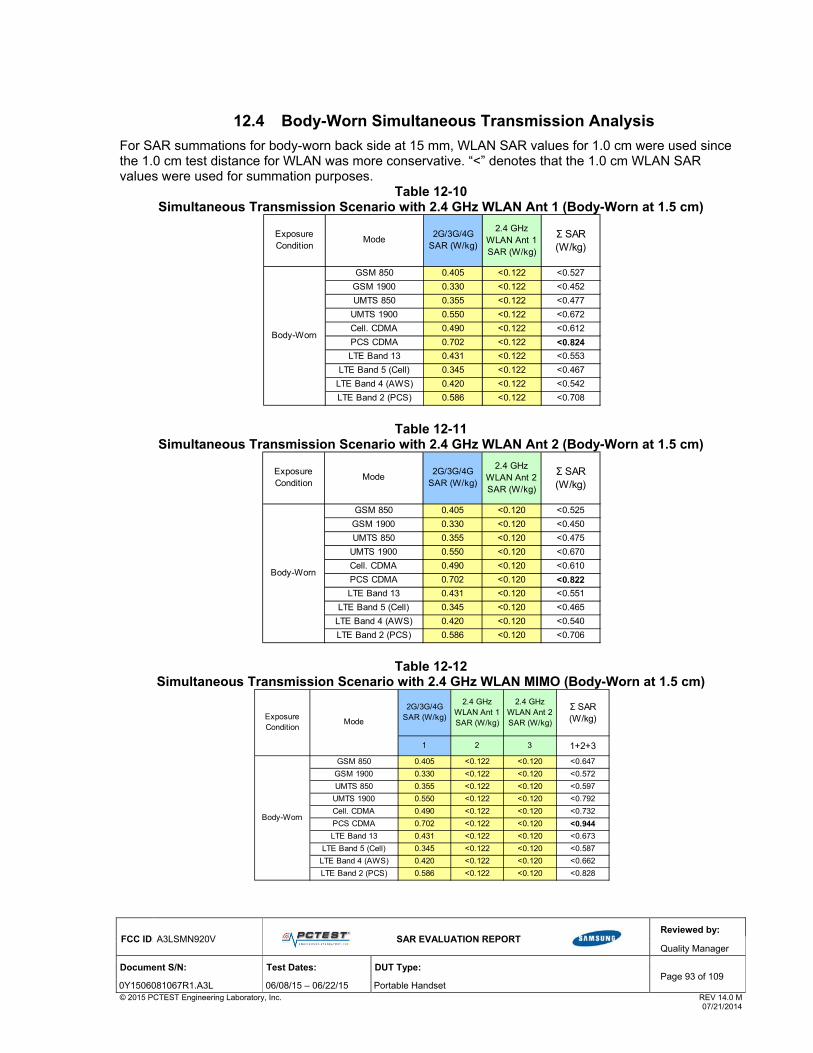
FCC ID: A3LSMN920V
SAR EVALUATION REPORT
Reviewed by:
Quality Manager
Document S/N: Test Dates: DUT Type: Page 93 of 109
0Y1506081067R1.A3L 06/08/15 – 06/22/15 Portable Handset © 2015 PCTEST Engineering Laboratory, Inc. REV 14.0 M 07/21/2014
12.4 Body-Worn Simultaneous Transmission Analysis
For SAR summations for body-worn back side at 15 mm, WLAN SAR values for 1.0 cm were used since the 1.0 cm test distance for WLAN was more conservative. “<” denotes that the 1.0 cm WLAN SAR values were used for summation purposes.
Table 12-10 Simultaneous Transmission Scenario with 2.4 GHz WLAN Ant 1 (Body-Worn at 1.5 cm)
Table 12-11 Simultaneous Transmission Scenario with 2.4 GHz WLAN Ant 2 (Body-Worn at 1.5 cm)
Table 12-12 Simultaneous Transmission Scenario with 2.4 GHz WLAN MIMO (Body-Worn at 1.5 cm)
2G/3G/4G SAR (W/kg)
2.4 GHz WLAN Ant 1 SAR (W/kg)
GSM 850 0.405 <0.122 <0.527
GSM 1900 0.330 <0.122 <0.452
UMTS 850 0.355 <0.122 <0.477
UMTS 1900 0.550 <0.122 <0.672
Cell. CDMA 0.490 <0.122 <0.612
PCS CDMA 0.702 <0.122 <0.824
LTE Band 13 0.431 <0.122 <0.553
LTE Band 5 (Cell) 0.345 <0.122 <0.467
LTE Band 4 (AWS) 0.420 <0.122 <0.542
LTE Band 2 (PCS) 0.586 <0.122 <0.708
Exposure Condition
Mode Σ SAR (W/kg)
Body-Worn
2G/3G/4G SAR (W/kg)
2.4 GHz WLAN Ant 2 SAR (W/kg)
GSM 850 0.405 <0.120 <0.525
GSM 1900 0.330 <0.120 <0.450
UMTS 850 0.355 <0.120 <0.475
UMTS 1900 0.550 <0.120 <0.670
Cell. CDMA 0.490 <0.120 <0.610
PCS CDMA 0.702 <0.120 <0.822
LTE Band 13 0.431 <0.120 <0.551
LTE Band 5 (Cell) 0.345 <0.120 <0.465
LTE Band 4 (AWS) 0.420 <0.120 <0.540
LTE Band 2 (PCS) 0.586 <0.120 <0.706
Body-Worn
Exposure Condition
Mode Σ SAR (W/kg)
2G/3G/4G SAR (W/kg)
2.4 GHz WLAN Ant 1 SAR (W/kg)
2.4 GHz WLAN Ant 2 SAR (W/kg)
1 2 3 1+2+3
GSM 850 0.405 <0.122 <0.120 <0.647
GSM 1900 0.330 <0.122 <0.120 <0.572
UMTS 850 0.355 <0.122 <0.120 <0.597
UMTS 1900 0.550 <0.122 <0.120 <0.792
Cell. CDMA 0.490 <0.122 <0.120 <0.732
PCS CDMA 0.702 <0.122 <0.120 <0.944
LTE Band 13 0.431 <0.122 <0.120 <0.673
LTE Band 5 (Cell) 0.345 <0.122 <0.120 <0.587
LTE Band 4 (AWS) 0.420 <0.122 <0.120 <0.662
LTE Band 2 (PCS) 0.586 <0.122 <0.120 <0.828
Body-Worn
Exposure Condition
Mode
Σ SAR (W/kg)

FCC ID: A3LSMN920V
SAR EVALUATION REPORT
Reviewed by:
Quality Manager
Document S/N: Test Dates: DUT Type: Page 94 of 109
0Y1506081067R1.A3L 06/08/15 – 06/22/15 Portable Handset © 2015 PCTEST Engineering Laboratory, Inc. REV 14.0 M 07/21/2014
Table 12-13 Simultaneous Transmission Scenario with 5 GHz WLAN Ant 1 (Body-Worn at 1.5 cm)
Table 12-14 Simultaneous Transmission Scenario with 5 GHz WLAN Ant 2 (Body-Worn at 1.5 cm)
Table 12-15 Simultaneous Transmission Scenario with 5 GHz WLAN MIMO (Body-Worn at 1.5 cm)
2G/3G/4G SAR (W/kg)
5 GHz WLAN Ant 1 SAR
(W/kg)
GSM 850 0.405 <0.261 <0.666
GSM 1900 0.330 <0.261 <0.591
UMTS 850 0.355 <0.261 <0.616
UMTS 1900 0.550 <0.261 <0.811
Cell. CDMA 0.490 <0.261 <0.751
PCS CDMA 0.702 <0.261 <0.963
LTE Band 13 0.431 <0.261 <0.692
LTE Band 5 (Cell) 0.345 <0.261 <0.606
LTE Band 4 (AWS) 0.420 <0.261 <0.681
LTE Band 2 (PCS) 0.586 <0.261 <0.847
Exposure Condition
Mode Σ SAR (W/kg)
Body-Worn
2G/3G/4G SAR (W/kg)
5 GHz WLAN Ant 2 SAR
(W/kg)
GSM 850 0.405 <0.101 <0.506
GSM 1900 0.330 <0.101 <0.431
UMTS 850 0.355 <0.101 <0.456
UMTS 1900 0.550 <0.101 <0.651
Cell. CDMA 0.490 <0.101 <0.591
PCS CDMA 0.702 <0.101 <0.803
LTE Band 13 0.431 <0.101 <0.532
LTE Band 5 (Cell) 0.345 <0.101 <0.446
LTE Band 4 (AWS) 0.420 <0.101 <0.521
LTE Band 2 (PCS) 0.586 <0.101 <0.687
Body-Worn
Exposure Condition
Mode Σ SAR (W/kg)
2G/3G/4G SAR (W/kg)
5 GHz WLAN Ant 1 SAR
(W/kg)
5 GHz WLAN Ant 2 SAR
(W/kg)
1 2 3 1+2+3
GSM 850 0.405 <0.261 <0.101 <0.767
GSM 1900 0.330 <0.261 <0.101 <0.692
UMTS 850 0.355 <0.261 <0.101 <0.717
UMTS 1900 0.550 <0.261 <0.101 <0.912
Cell. CDMA 0.490 <0.261 <0.101 <0.852
PCS CDMA 0.702 <0.261 <0.101 <1.064
LTE Band 13 0.431 <0.261 <0.101 <0.793
LTE Band 5 (Cell) 0.345 <0.261 <0.101 <0.707
LTE Band 4 (AWS) 0.420 <0.261 <0.101 <0.782
LTE Band 2 (PCS) 0.586 <0.261 <0.101 <0.948
Exposure Condition
Mode
Σ SAR (W/kg)
Body-Worn

FCC ID: A3LSMN920V
SAR EVALUATION REPORT
Reviewed by:
Quality Manager
Document S/N: Test Dates: DUT Type: Page 95 of 109
0Y1506081067R1.A3L 06/08/15 – 06/22/15 Portable Handset © 2015 PCTEST Engineering Laboratory, Inc. REV 14.0 M 07/21/2014
Table 12-16 Simultaneous Transmission Scenario with 2.4 GHz WLAN Ant 1 and 5 GHz WLAN Ant 2
(Body-Worn at 1.5 cm)
Table 12-17 Simultaneous Transmission Scenario with 2.4 GHz WLAN Ant 2 and 5 GHz WLAN Ant 1
(Body-Worn at 1.5 cm)
Table 12-18 Simultaneous Transmission Scenario with Bluetooth (Body-Worn at 1.5 cm)
Note: Bluetooth SAR was not required to be measured per FCC KDB 447498. Estimated SAR results
were used in the above table to determine simultaneous transmission SAR test exclusion.
2G/3G/4G SAR (W/kg)
2.4 GHz WLAN Ant 1 SAR (W/kg)
5 GHz WLAN Ant 2 SAR
(W/kg)
1 2 3 1+2+3
GSM 850 0.405 <0.122 <0.101 <0.628
GSM 1900 0.330 <0.122 <0.101 <0.553
UMTS 850 0.355 <0.122 <0.101 <0.578
UMTS 1900 0.550 <0.122 <0.101 <0.773
Cell. CDMA 0.490 <0.122 <0.101 <0.713
PCS CDMA 0.702 <0.122 <0.101 <0.925
LTE Band 13 0.431 <0.122 <0.101 <0.654
LTE Band 5 (Cell) 0.345 <0.122 <0.101 <0.568
LTE Band 4 (AWS) 0.420 <0.122 <0.101 <0.643
LTE Band 2 (PCS) 0.586 <0.122 <0.101 <0.809
Body-Worn
Exposure Condition
Mode
Σ SAR (W/kg)
2G/3G/4G SAR (W/kg)
2.4 GHz WLAN Ant 2 SAR (W/kg)
5 GHz WLAN Ant 1 SAR
(W/kg)
1 2 3 1+2+3
GSM 850 0.405 <0.120 <0.261 <0.786
GSM 1900 0.330 <0.120 <0.261 <0.711
UMTS 850 0.355 <0.120 <0.261 <0.736
UMTS 1900 0.550 <0.120 <0.261 <0.931
Cell. CDMA 0.490 <0.120 <0.261 <0.871
PCS CDMA 0.702 <0.120 <0.261 <1.083
LTE Band 13 0.431 <0.120 <0.261 <0.812
LTE Band 5 (Cell) 0.345 <0.120 <0.261 <0.726
LTE Band 4 (AWS) 0.420 <0.120 <0.261 <0.801
LTE Band 2 (PCS) 0.586 <0.120 <0.261 <0.967
Exposure Condition
Mode
Σ SAR (W/kg)
Body-Worn
2G/3G/4G SAR (W/kg)
Bluetooth SAR (W/kg)
GSM 850 0.405 0.196 0.601
GSM 1900 0.330 0.196 0.526
UMTS 850 0.355 0.196 0.551
UMTS 1900 0.550 0.196 0.746
Cell. CDMA 0.490 0.196 0.686
PCS CDMA 0.702 0.196 0.898
LTE Band 13 0.431 0.196 0.627
LTE Band 5 (Cell) 0.345 0.196 0.541
LTE Band 4 (AWS) 0.420 0.196 0.616
LTE Band 2 (PCS) 0.586 0.196 0.782
Exposure Condition
Mode Σ SAR (W/kg)
Body-Worn

FCC ID: A3LSMN920V
SAR EVALUATION REPORT
Reviewed by:
Quality Manager
Document S/N: Test Dates: DUT Type: Page 96 of 109
0Y1506081067R1.A3L 06/08/15 – 06/22/15 Portable Handset © 2015 PCTEST Engineering Laboratory, Inc. REV 14.0 M 07/21/2014
12.5 Hotspot SAR Simultaneous Transmission Analysis
Table 12-19 Simultaneous Transmission Scenario (2.4 GHz WLAN Ant 1 Hotspot at 1.0 cm)
Table 12-20 Simultaneous Transmission Scenario (2.4 GHz WLAN Ant 2 at 1.0 cm)
Table 12-21 Simultaneous Transmission Scenario (2.4 GHz WLAN MIMO at 1.0 cm)
2G/3G/4G SAR (W/kg)
2.4 GHz WLAN Ant 1 SAR (W/kg)
GPRS 850 1.001 0.122 1.123
GPRS 1900 1.077 0.122 1.199
UMTS 850 0.591 0.122 0.713
UMTS 1900 1.052 0.122 1.174
Cell. EVDO 0.970 0.122 1.092
PCS EVDO 0.993 0.122 1.115
LTE Band 13 0.705 0.122 0.827
LTE Band 5 (Cell) 0.649 0.122 0.771
LTE Band 4 (AWS) 1.034 0.122 1.156
LTE Band 2 (PCS) 1.096 0.122 1.218
Hotspot SAR
Exposure Condition
Mode Σ SAR (W/kg)
2G/3G/4G SAR (W/kg)
2.4 GHz WLAN Ant 2 SAR (W/kg)
GPRS 850 1.001 0.120 1.121
GPRS 1900 1.077 0.120 1.197
UMTS 850 0.591 0.120 0.711
UMTS 1900 1.052 0.120 1.172
Cell. EVDO 0.970 0.120 1.090
PCS EVDO 0.993 0.120 1.113
LTE Band 13 0.705 0.120 0.825
LTE Band 5 (Cell) 0.649 0.120 0.769
LTE Band 4 (AWS) 1.034 0.120 1.154
LTE Band 2 (PCS) 1.096 0.120 1.216
Hotspot SAR
Exposure Condition
Mode Σ SAR (W/kg)
2G/3G/4G SAR (W/kg)
2.4 GHz WLAN Ant 1 SAR (W/kg)
2.4 GHz WLAN Ant 2 SAR (W/kg)
1 2 3 1+2+3
GPRS 850 1.001 0.122 0.120 1.243
GPRS 1900 1.077 0.122 0.120 1.319
UMTS 850 0.591 0.122 0.120 0.833
UMTS 1900 1.052 0.122 0.120 1.294
Cell. EVDO 0.970 0.122 0.120 1.212
PCS EVDO 0.993 0.122 0.120 1.235
LTE Band 13 0.705 0.122 0.120 0.947
LTE Band 5 (Cell) 0.649 0.122 0.120 0.891
LTE Band 4 (AWS) 1.034 0.122 0.120 1.276
LTE Band 2 (PCS) 1.096 0.122 0.120 1.338
Hotspot SAR
Exposure Condition
Mode
Σ SAR (W/kg)

FCC ID: A3LSMN920V
SAR EVALUATION REPORT
Reviewed by:
Quality Manager
Document S/N: Test Dates: DUT Type: Page 97 of 109
0Y1506081067R1.A3L 06/08/15 – 06/22/15 Portable Handset © 2015 PCTEST Engineering Laboratory, Inc. REV 14.0 M 07/21/2014
Table 12-22 Simultaneous Transmission Scenario (5 GHz WLAN Ant 1 at 1.0 cm)
Table 12-23 Simultaneous Transmission Scenario (5 GHz WLAN Ant 2 at 1.0 cm)
Table 12-24 Simultaneous Transmission Scenario (5 GHz WLAN MIMO at 1.0 cm)
2G/3G/4G SAR (W/kg)
5 GHz WLAN Ant 1 SAR
(W/kg)
GPRS 850 1.001 0.261 1.262
GPRS 1900 1.077 0.261 1.338
UMTS 850 0.591 0.261 0.852
UMTS 1900 1.052 0.261 1.313
Cell. EVDO 0.970 0.261 1.231
PCS EVDO 0.993 0.261 1.254
LTE Band 13 0.705 0.261 0.966
LTE Band 5 (Cell) 0.649 0.261 0.910
LTE Band 4 (AWS) 1.034 0.261 1.295
LTE Band 2 (PCS) 1.096 0.261 1.357
Hotspot SAR
Exposure Condition
Mode Σ SAR (W/kg)
2G/3G/4G SAR (W/kg)
5 GHz WLAN Ant 2 SAR
(W/kg)
GPRS 850 1.001 0.095 1.096
GPRS 1900 1.077 0.095 1.172
UMTS 850 0.591 0.095 0.686
UMTS 1900 1.052 0.095 1.147
Cell. EVDO 0.970 0.095 1.065
PCS EVDO 0.993 0.095 1.088
LTE Band 13 0.705 0.095 0.800
LTE Band 5 (Cell) 0.649 0.095 0.744
LTE Band 4 (AWS) 1.034 0.095 1.129
LTE Band 2 (PCS) 1.096 0.095 1.191
Hotspot SAR
Exposure Condition
Mode Σ SAR (W/kg)
2G/3G/4G SAR (W/kg)
5 GHz WLAN Ant 1 SAR
(W/kg)
5 GHz WLAN Ant 2 SAR
(W/kg)
1 2 3 1+2+3
GPRS 850 1.001 0.261 0.095 1.357
GPRS 1900 1.077 0.261 0.095 1.433
UMTS 850 0.591 0.261 0.095 0.947
UMTS 1900 1.052 0.261 0.095 1.408
Cell. EVDO 0.970 0.261 0.095 1.326
PCS EVDO 0.993 0.261 0.095 1.349
LTE Band 13 0.705 0.261 0.095 1.061
LTE Band 5 (Cell) 0.649 0.261 0.095 1.005
LTE Band 4 (AWS) 1.034 0.261 0.095 1.390
LTE Band 2 (PCS) 1.096 0.261 0.095 1.452
Hotspot SAR
Exposure Condition
Mode
Σ SAR (W/kg)

FCC ID: A3LSMN920V
SAR EVALUATION REPORT
Reviewed by:
Quality Manager
Document S/N: Test Dates: DUT Type: Page 98 of 109
0Y1506081067R1.A3L 06/08/15 – 06/22/15 Portable Handset © 2015 PCTEST Engineering Laboratory, Inc. REV 14.0 M 07/21/2014
Table 12-25 Simultaneous Transmission Scenario
(2.4 GHz WLAN Ant 1 and 5 GHz WLAN Ant 2 at 1.0 cm)
Table 12-26 Simultaneous Transmission Scenario
(2.4 GHz WLAN Ant 2 and 5 GHz WLAN Ant 1 at 1.0 cm)
12.6 Extremity SAR Simultaneous Transmission Analysis
1. Per FCC KDB Publication 648474 D04 Handset SAR v01r01, the devices edges with antennas more than 2.5 cm from edge are not required to be evaluated for SAR (“-“).
2. For SAR summations for extremity front side at 3 mm, Extremity WLAN SAR values for 0.0 cm were used since the 0.0 cm test distance was more conservative.“<” denotes that the 0.0 cm Extremity WLAN SAR values were used for summation purposes.
3. For SAR summations for extremity back side at 4 mm, Extremity WLAN SAR values for 0.0 cm were used since the 0.0 cm test distance was more conservative.“<” denotes that the 0.0 cm Extremity WLAN SAR values were used for summation purposes.
4. (*) For WLAN devices edges with antennas less than 2.5 cm from edge that were not required to be evaluated for SAR, the worst case Extremity WLAN SAR was used as it is more conservative.
5. Per FCC KDB Publication 648474 D04 Handset SAR v01r02, hand SAR tests were not required when wireless router mode does not apply and if wireless router 1g SAR (scaled to the maximum output power, including tolerance) < 1.2 W/kg. Therefore no further analysis was required to determine that SAR limit would not be exceed for all possible simultaneous scenarios, including those involving bands/modes not required to be evaluated for hand SAR.
6. Extremity WLAN SAR was not required for bottom edge; thus no additional simultaneous evaluation besides included in this section was required to determine that possible simultaneous scenarios would not exceed the SAR limit.
2G/3G/4G SAR (W/kg)
2.4 GHz WLAN Ant 1 SAR (W/kg)
5 GHz WLAN Ant 2 SAR
(W/kg)
1 2 3 1+2+3
GPRS 850 1.001 0.122 0.095 1.218
GPRS 1900 1.077 0.122 0.095 1.294
UMTS 850 0.591 0.122 0.095 0.808
UMTS 1900 1.052 0.122 0.095 1.269
Cell. EVDO 0.970 0.122 0.095 1.187
PCS EVDO 0.993 0.122 0.095 1.210
LTE Band 13 0.705 0.122 0.095 0.922
LTE Band 5 (Cell) 0.649 0.122 0.095 0.866
LTE Band 4 (AWS) 1.034 0.122 0.095 1.251
LTE Band 2 (PCS) 1.096 0.122 0.095 1.313
Hotspot SAR
Exposure Condition
Mode
Σ SAR (W/kg)
2G/3G/4G SAR (W/kg)
2.4 GHz WLAN Ant 2 SAR (W/kg)
5 GHz WLAN Ant 1 SAR
(W/kg)
1 2 3 1+2+3
GPRS 850 1.001 0.120 0.261 1.382
GPRS 1900 1.077 0.120 0.261 1.458
UMTS 850 0.591 0.120 0.261 0.972
UMTS 1900 1.052 0.120 0.261 1.433
Cell. EVDO 0.970 0.120 0.261 1.351
PCS EVDO 0.993 0.120 0.261 1.374
LTE Band 13 0.705 0.120 0.261 1.086
LTE Band 5 (Cell) 0.649 0.120 0.261 1.030
LTE Band 4 (AWS) 1.034 0.120 0.261 1.415
LTE Band 2 (PCS) 1.096 0.120 0.261 1.477
Hotspot SAR
Exposure Condition
Mode
Σ SAR (W/kg)

FCC ID: A3LSMN920V
SAR EVALUATION REPORT
Reviewed by:
Quality Manager
Document S/N: Test Dates: DUT Type: Page 99 of 109
0Y1506081067R1.A3L 06/08/15 – 06/22/15 Portable Handset © 2015 PCTEST Engineering Laboratory, Inc. REV 14.0 M 07/21/2014
Table 12-27 Simultaneous Transmission Scenario - 5 GHz WLAN Ant 1 (Extremity at 0.0 cm)
Table 12-28 Simultaneous Transmission Scenario - 5 GHz WLAN Ant 2 (Extremity at 0.0 cm)
GPRS 1900 SAR (W/kg)
5 GHz WLAN Ant 1 SAR
(W/kg)
Back 1.453 1.202 2.655Front 1.351 1.256 2.607Top - *1.256 *1.256
Bottom 1.575 - 1.575Right 0.446 - 0.446Left 0.595 *1.256 *1.851
Σ SAR (W/kg)
Simult Tx
Extremity SAR
ConfigurationUMTS 1900 SAR (W/kg)
5 GHz WLAN Ant 1 SAR
(W/kg)
Back 1.857 1.202 3.059Front 1.837 1.256 3.093Top - *1.256 *1.256
Bottom 2.115 - 2.115Right 0.407 - 0.407Left 0.679 *1.256 *1.935
Σ SAR (W/kg)
Simult Tx
Extremity SAR
Configuration
PCS EVDO SAR (W/kg)
5 GHz WLAN Ant 1 SAR
(W/kg)
Back 2.352 1.202 3.554Front 2.385 1.256 3.641Top - *1.256 *1.256
Bottom 2.503 - 2.503Right 0.336 - 0.336Left 0.999 *1.256 *2.255
Σ SAR (W/kg)
Simult Tx
Extremity SAR
ConfigurationLTE Band 4 (AWS) SAR
(W/kg)
5 GHz WLAN Ant 1 SAR
(W/kg)
Back 2.279 1.202 3.481Front 2.486 1.256 3.742Top - *1.256 *1.256
Bottom 2.521 - 2.521Right 0.286 - 0.286Left 0.423 *1.256 *1.679
Σ SAR (W/kg)
Simult Tx
Extremity SAR
Configuration
LTE Band 2 (PCS) SAR
(W/kg)
5 GHz WLAN Ant 1 SAR
(W/kg)
Back 2.196 1.202 3.398Front 1.899 1.256 3.155Top - *1.256 *1.256
Bottom 2.335 - 2.335Right 0.317 - 0.317Left 0.855 *1.256 *2.111
Σ SAR (W/kg)
Simult Tx
Extremity SAR
Configuration
GPRS 1900 SAR (W/kg)
5 GHz WLAN Ant 2 SAR
(W/kg)
Back 1.453 0.618 2.071Front 1.351 *0.618 *1.969Top - *0.618 *0.618
Bottom 1.575 - 1.575Right 0.446 - 0.446Left 0.595 *0.618 *1.213
Σ SAR (W/kg)
Simult Tx
Extremity SAR
ConfigurationUMTS 1900 SAR (W/kg)
5 GHz WLAN Ant 2 SAR
(W/kg)
Back 1.857 0.618 2.475Front 1.837 *0.618 *2.455Top - *0.618 *0.618
Bottom 2.115 - 2.115Right 0.407 - 0.407Left 0.679 *0.618 *1.297
Σ SAR (W/kg)
Simult Tx
Extremity SAR
Configuration
PCS EVDO SAR (W/kg)
5 GHz WLAN Ant 2 SAR
(W/kg)
Back 2.352 0.618 2.970Front 2.385 *0.618 *3.003Top - *0.618 *0.618
Bottom 2.503 - 2.503Right 0.336 - 0.336Left 0.999 *0.618 *1.617
Σ SAR (W/kg)
Simult Tx
Extremity SAR
ConfigurationLTE Band 4 (AWS) SAR
(W/kg)
5 GHz WLAN Ant 2 SAR
(W/kg)
Back 2.279 0.618 2.897Front 2.486 *0.618 *3.104Top - *0.618 *0.618
Bottom 2.521 - 2.521Right 0.286 - 0.286Left 0.423 *0.618 *1.041
Σ SAR (W/kg)
Simult Tx
Extremity SAR
Configuration
LTE Band 2 (PCS) SAR
(W/kg)
5 GHz WLAN Ant 2 SAR
(W/kg)
Back 2.196 0.618 2.814Front 1.899 *0.618 *2.517Top - *0.618 *0.618
Bottom 2.335 - 2.335Right 0.317 - 0.317Left 0.855 *0.618 *1.473
Σ SAR (W/kg)
Simult Tx
Extremity SAR
Configuration

FCC ID: A3LSMN920V
SAR EVALUATION REPORT
Reviewed by:
Quality Manager
Document S/N: Test Dates: DUT Type: Page 100 of 109
0Y1506081067R1.A3L 06/08/15 – 06/22/15 Portable Handset © 2015 PCTEST Engineering Laboratory, Inc. REV 14.0 M 07/21/2014
Table 12-29 Simultaneous Transmission Scenario - 5 GHz WLAN MIMO (Extremity at 0.0 cm)
Table 12-30 Simultaneous Transmission Scenario - Bluetooth (Extremity at 0.0 cm)
Note: Bluetooth SAR was not required to be measured per FCC KDB 447498. Estimated SAR results
were used in the above table to determine simultaneous transmission SAR test exclusion.
GPRS 1900 SAR (W/kg)
5 GHz WLAN MIMO SAR
(W/kg)
Back 1.453 1.013 2.466Front 1.351 0.848 2.199Top - *1.013 *1.013
Bottom 1.575 - 1.575Right 0.446 - 0.446Left 0.595 *1.013 *1.608
Σ SAR (W/kg)
Simult Tx
Extremity SAR
ConfigurationUMTS 1900 SAR (W/kg)
5 GHz WLAN MIMO SAR
(W/kg)
Back 1.857 1.013 2.870Front 1.837 0.848 2.685Top - *1.013 *1.013
Bottom 2.115 - 2.115Right 0.407 - 0.407Left 0.679 *1.013 *1.692
Σ SAR (W/kg)
Simult Tx
Extremity SAR
Configuration
PCS EVDO SAR (W/kg)
5 GHz WLAN MIMO SAR
(W/kg)
Back 2.352 1.013 3.365Front 2.385 0.848 3.233Top - *1.013 *1.013
Bottom 2.503 - 2.503Right 0.336 - 0.336Left 0.999 *1.013 *2.012
Σ SAR (W/kg)
Simult Tx
Extremity SAR
ConfigurationLTE Band 4 (AWS) SAR
(W/kg)
5 GHz WLAN MIMO SAR
(W/kg)
Back 2.279 1.013 3.292Front 2.486 0.848 3.334Top - *1.013 *1.013
Bottom 2.521 - 2.521Right 0.286 - 0.286Left 0.423 *1.013 *1.436
Σ SAR (W/kg)
Simult Tx
Extremity SAR
Configuration
LTE Band 2 (PCS) SAR
(W/kg)
5 GHz WLAN MIMO SAR
(W/kg)
Back 2.196 1.013 3.209Front 1.899 0.848 2.747Top - *1.013 *1.013
Bottom 2.335 - 2.335Right 0.317 - 0.317Left 0.855 *1.013 *1.868
Σ SAR (W/kg)
Simult Tx
Extremity SAR
Configuration
GPRS 1900 SAR (W/kg)
Bluetooth SAR (W/kg)
Back 1.453 0.588 2.041Front 1.351 0.588 1.939Top - 0.588 0.588
Bottom 1.575 - 1.575Right 0.446 - 0.446Left 0.595 0.588 1.183
Simult Tx
Extremity SAR
ConfigurationΣ SAR (W/kg)
UMTS 1900 SAR (W/kg)
Bluetooth SAR (W/kg)
Back 1.857 0.588 2.445Front 1.837 0.588 2.425Top - 0.588 0.588
Bottom 2.115 - 2.115Right 0.679 - 0.679Left 0.018 0.588 0.606
Simult Tx
Extremity SAR
ConfigurationΣ SAR (W/kg)
PCS EVDO SAR (W/kg)
Bluetooth SAR (W/kg)
Back 2.352 0.588 2.940Front 2.385 0.588 2.973Top - 0.588 0.588
Bottom 2.503 - 2.503Right 0.336 - 0.336Left 0.999 0.588 1.587
Simult Tx
Extremity SAR
ConfigurationΣ SAR (W/kg)
LTE Band 4 (AWS) SAR
(W/kg)
Bluetooth SAR (W/kg)
Back 2.279 0.588 2.867Front 2.486 0.588 3.074Top - 0.588 0.588
Bottom 2.521 - 2.521Right 0.286 - 0.286Left 0.423 0.588 1.011
Simult Tx
Extremity SAR
ConfigurationΣ SAR (W/kg)
LTE Band 2 (PCS) SAR
(W/kg)
Bluetooth SAR (W/kg)
Back 2.196 0.588 2.784Front 1.899 0.588 2.487Top - 0.588 0.588
Bottom 2.335 - 2.335Right 0.317 - 0.317Left 0.855 0.588 1.443
Simult Tx
Extremity SAR
ConfigurationΣ SAR (W/kg)
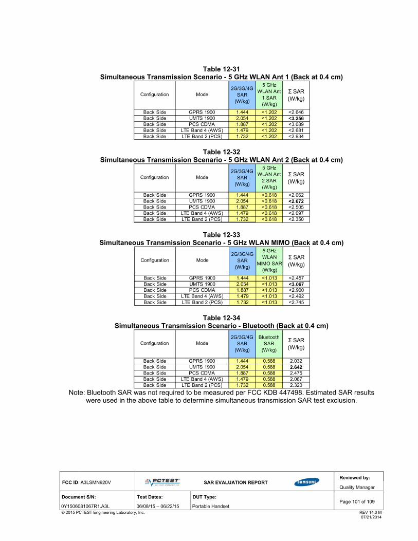
FCC ID: A3LSMN920V
SAR EVALUATION REPORT
Reviewed by:
Quality Manager
Document S/N: Test Dates: DUT Type: Page 101 of 109
0Y1506081067R1.A3L 06/08/15 – 06/22/15 Portable Handset © 2015 PCTEST Engineering Laboratory, Inc. REV 14.0 M 07/21/2014
Table 12-31 Simultaneous Transmission Scenario - 5 GHz WLAN Ant 1 (Back at 0.4 cm)
Table 12-32 Simultaneous Transmission Scenario - 5 GHz WLAN Ant 2 (Back at 0.4 cm)
Table 12-33 Simultaneous Transmission Scenario - 5 GHz WLAN MIMO (Back at 0.4 cm)
Table 12-34 Simultaneous Transmission Scenario - Bluetooth (Back at 0.4 cm)
Note: Bluetooth SAR was not required to be measured per FCC KDB 447498. Estimated SAR results
were used in the above table to determine simultaneous transmission SAR test exclusion.
2G/3G/4G SAR
(W/kg)
5 GHz WLAN Ant
1 SAR (W/kg)
Back Side GPRS 1900 1.444 <1.202 <2.646Back Side UMTS 1900 2.054 <1.202 <3.256Back Side PCS CDMA 1.887 <1.202 <3.089Back Side LTE Band 4 (AWS) 1.479 <1.202 <2.681Back Side LTE Band 2 (PCS) 1.732 <1.202 <2.934
Σ SAR (W/kg)
ModeConfiguration
2G/3G/4G SAR
(W/kg)
5 GHz WLAN Ant
2 SAR (W/kg)
Back Side GPRS 1900 1.444 <0.618 <2.062Back Side UMTS 1900 2.054 <0.618 <2.672Back Side PCS CDMA 1.887 <0.618 <2.505Back Side LTE Band 4 (AWS) 1.479 <0.618 <2.097Back Side LTE Band 2 (PCS) 1.732 <0.618 <2.350
Σ SAR (W/kg)
ModeConfiguration
2G/3G/4G SAR
(W/kg)
5 GHz WLAN
MIMO SAR (W/kg)
Σ SAR (W/kg)
Back Side GPRS 1900 1.444 <1.013 <2.457Back Side UMTS 1900 2.054 <1.013 <3.067Back Side PCS CDMA 1.887 <1.013 <2.900Back Side LTE Band 4 (AWS) 1.479 <1.013 <2.492Back Side LTE Band 2 (PCS) 1.732 <1.013 <2.745
ModeConfiguration
2G/3G/4G SAR
(W/kg)
Bluetooth SAR
(W/kg)
Back Side GPRS 1900 1.444 0.588 2.032Back Side UMTS 1900 2.054 0.588 2.642Back Side PCS CDMA 1.887 0.588 2.475Back Side LTE Band 4 (AWS) 1.479 0.588 2.067Back Side LTE Band 2 (PCS) 1.732 0.588 2.320
Σ SAR (W/kg)
ModeConfiguration

FCC ID: A3LSMN920V
SAR EVALUATION REPORT
Reviewed by:
Quality Manager
Document S/N: Test Dates: DUT Type: Page 102 of 109
0Y1506081067R1.A3L 06/08/15 – 06/22/15 Portable Handset © 2015 PCTEST Engineering Laboratory, Inc. REV 14.0 M 07/21/2014
Table 12-35 Simultaneous Transmission Scenario - 5 GHz WLAN Ant 1 (Front at 0.3 cm)
Table 12-36 Simultaneous Transmission Scenario - 5 GHz WLAN Ant 2 (Front at 0.3 cm)
Table 12-37 Simultaneous Transmission Scenario - 5 GHz WLAN MIMO (Front at 0.3 cm)
Table 12-38 Simultaneous Transmission Scenario - Bluetooth (Front at 0.3 cm)
Note: Bluetooth SAR was not required to be measured per FCC KDB 447498. Estimated SAR results
were used in the above table to determine simultaneous transmission SAR test exclusion.
12.7 Simultaneous Transmission Conclusion
The above numerical summed SAR results for all the worst-case simultaneous transmission conditions were below the SAR limit. Therefore, the above analysis is sufficient to determine that simultaneous transmission cases will not exceed the SAR limit and therefore no measured volumetric simultaneous SAR summation is required per FCC KDB Publication 447498 D01v05 and IEEE 1528-2013 Section 6.3.4.1.2.
2G/3G/4G SAR
(W/kg)
5 GHz WLAN Ant 1 SAR
(W/kg)
Front Side GSM 1900 1.857 <1.256 <3.113Front Side UMTS 1900 2.572 <1.256 <3.828Front Side PCS CDMA 2.368 <1.256 <3.624Front Side LTE Band 4 (AWS) 2.112 <1.256 <3.368Front Side LTE Band 2 (PCS) 1.984 <1.256 <3.240
Configuration Mode Σ SAR (W/kg)
2G/3G/4G SAR
(W/kg)
5 GHz WLAN Ant 2 SAR
(W/kg)
Front Side GSM 1900 1.857 <0.618* <2.475*Front Side UMTS 1900 2.572 <0.618* <3.190*Front Side PCS CDMA 2.368 <0.618* <2.986*Front Side LTE Band 4 (AWS) 2.112 <0.618* <2.730*Front Side LTE Band 2 (PCS) 1.984 <0.618* <2.602*
Configuration Mode Σ SAR (W/kg)
2G/3G/4G SAR
(W/kg)
5 GHz WLAN MIMO SAR
(W/kg)
Σ SAR (W/kg)
Front Side GSM 1900 1.857 <0.848 <2.705Front Side UMTS 1900 2.572 <0.848 <3.420Front Side PCS CDMA 2.368 <0.848 <3.216Front Side LTE Band 4 (AWS) 2.112 <0.848 <2.960Front Side LTE Band 2 (PCS) 1.984 <0.848 <2.832
Configuration Mode
2G/3G/4G SAR
(W/kg)
Bluetooth SAR (W/kg)
Front Side GSM 1900 1.857 0.588 2.445Front Side UMTS 1900 2.572 0.588 3.160Front Side PCS CDMA 2.368 0.588 2.956Front Side LTE Band 4 (AWS) 2.112 0.588 2.700Front Side LTE Band 2 (PCS) 1.984 0.588 2.572
Configuration Mode Σ SAR (W/kg)

FCC ID: A3LSMN920V
SAR EVALUATION REPORT
Reviewed by:
Quality Manager
Document S/N: Test Dates: DUT Type: Page 103 of 109
0Y1506081067R1.A3L 06/08/15 – 06/22/15 Portable Handset © 2015 PCTEST Engineering Laboratory, Inc. REV 14.0 M 07/21/2014
13 S A R M E A S U R E M E N T V A R I A B I L I T Y
13.1 Measurement Variability
Per FCC KDB Publication 865664 D01v01, SAR measurement variability was assessed for each frequency band, which was determined by the SAR probe calibration point and tissue-equivalent medium used for the device measurements. When both head and body tissue-equivalent media were required for SAR measurements in a frequency band, the variability measurement procedures were applied to the tissue medium with the highest measured SAR, using the highest measured SAR configuration for that tissue-equivalent medium. These additional measurements were repeated after the completion of all measurements requiring the same head or body tissue-equivalent medium in a frequency band. The test device was returned to ambient conditions (normal room temperature) with the battery fully charged before it was re-mounted on the device holder for the repeated measurement(s) to minimize any unexpected variations in the repeated results. Per FCC KDB Publication 865664 D01v01, Extremity SAR measurement variability was assessed since measured 1g SAR for some frequency band was above 0.8 W/kg and measured 10g SAR for some frequency band was above 2.0 W/kg. SAR Measurement Variability was assessed using the following procedures for each frequency band:
1) When the original highest measured SAR is ≥ 0.80 W/kg, the measurement was repeated once. 2) A second repeated measurement was preformed only if the ratio of largest to smallest SAR for the original
and first repeated measurements was > 1.20 or when the original or repeated measurement was ≥ 1.45 W/kg (~ 10% from the 1-g SAR limit).
3) A third repeated measurement was performed only if the original, first or second repeated measurement was ≥ 1.5 W/kg and the ratio of largest to smallest SAR for the original, first and second repeated measurements is > 1.20.
4) Repeated measurements are not required when the original highest measured SAR is < 0.80 W/kg 5) 10g Extremity SAR measurement variability analysis applies a factor of 2.5 to the procedures outlined
above. Table 13-1
Body SAR Measurement Variability Results
Table 13-2
Extremity SAR Measurement Variability Results
13.2 Measurement Uncertainty
The measured 1g SAR was <1.5 W/kg and 10g SAR was <3.75 W/kg for all frequency bands. Therefore, per KDB Publication 865664 D01v01, the extended measurement uncertainty analysis per IEEE 1528-2003 was not required.
Measured SAR (1g)
1st Repeated SAR (1g)
2nd Repeated SAR (1g)
3rd Repeated SAR (1g)
MHz Ch. (W/kg) (W/kg) (W/kg) (W/kg)
835 824.20 128 GSM 850 GPRS 4 front 10 mm 0.892 0.840 1.06 N/A N/A N/A N/A
1900 1909.80 810 GSM 1900 GPRS 4 bottom 10 mm 1.050 1.060 1.01 N/A N/A N/A N/A
1750 1732.50 20175 LTE Band 4 (AWS)QPSK, 100 RB,
0 RB OffsetN/A bottom 10 mm 0.898 0.835 1.08 N/A N/A N/A N/A
averaged over 1 gram
Body
BODY VARIABILITY RESULTS
ANSI / IEEE C95.1 1992 - SAFETY LIMIT
Spatial Peak
Uncontrolled Exposure/General Population
RatioRatio RatioBand# of Time
SlotsSide Spacing
FREQUENCYMode Service
1.6 W/kg (mW/g)
Measured SAR (10g)
1st Repeated SAR (10g)
2nd Repeated SAR (10g)
3rd Repeated SAR (10g)
MHz Ch. (W/kg) (W/kg) (W/kg) (W/kg)
1900 1880.00 600 PCS CDMA EVDO Rev. 0 bottom 5 mm 3.030 3.070 1.01 N/A N/A N/A N/A
1750 1732.50 20175 LTE Band 4 (AWS)QPSK, 1 RB, 0 RB
Offsetbottom 0 mm 2.230 2.250 1.01 N/A N/A N/A N/A
EXTREMITY VARIABILITY RESULTS
BandFREQUENCY
Mode Service Side Spacing Ratio
Uncontrolled Exposure/General Population averaged over 10 grams
Ratio Ratio
ANSI / IEEE C95.1 1992 - SAFETY LIMIT Extremity
Spatial Peak 4.0 W/kg (mW/g)

FCC ID: A3LSMN920V
SAR EVALUATION REPORT
Reviewed by:
Quality Manager
Document S/N: Test Dates: DUT Type: Page 104 of 109
0Y1506081067R1.A3L 06/08/15 – 06/22/15 Portable Handset © 2015 PCTEST Engineering Laboratory, Inc. REV 14.0 M 07/21/2014
14 E Q U I P M E N T L I S T
Note:
1. CBT (Calibrated Before Testing). Prior to testing, the measurement paths containing a cable, amplifier, attenuator, coupler or filter were connected to a calibrated source (i.e. a signal generator) to determine the losses of the measurement path. The power meter offset was then adjusted to compensate for the measurement system losses. This level offset is stored within the power meter before measurements are made. This calibration verification procedure applies to the system verification and output power measurements. The calibrated reading is then taken directly from the power meter after compensation of the losses for all final power measurements.
2. Each equipment item was used solely within its respective calibration period.
Manufacturer Model Description Cal Date Cal Interval Cal Due Serial Number
SPEAG D1750V2 1750 MHz SAR Dipole 4/15/2015 Annual 4/15/2016 1051
SPEAG D1900V2 1900 MHz SAR Dipole 4/14/2015 Annual 4/14/2016 5d141
SPEAG D1900V2 1900 MHz SAR Dipole 7/23/2014 Annual 7/23/2015 5d149
SPEAG D2450V2 2450 MHz SAR Dipole 8/11/2014 Annual 8/11/2015 719
SPEAG D5GHzV2 5 GHz SAR Dipole 1/21/2015 Annual 1/21/2016 1057
SPEAG D750V3 750 MHz Dipole 1/16/2015 Annual 1/16/2016 1003
SPEAG D835V2 835 MHz SAR Dipole 1/16/2015 Annual 1/16/2016 4d132
SPEAG D835V2 835 MHz SAR Dipole 7/24/2014 Annual 7/24/2015 4d133
SPEAG DAE4 Dasy Data Acquisition Electronics 1/14/2015 Annual 1/14/2016 1272
SPEAG DAE4 Dasy Data Acquisition Electronics 9/17/2014 Annual 9/17/2015 1323
SPEAG DAE4 Dasy Data Acquisition Electronics 3/13/2015 Annual 3/13/2016 1334
SPEAG DAE4 Dasy Data Acquisition Electronics 9/18/2014 Annual 9/18/2015 1364
SPEAG DAE4 Dasy Data Acquisition Electronics 10/23/2014 Annual 10/23/2015 1408
SPEAG DAK‐3.5 Dielectric Assessment Kit 10/21/2014 Annual 10/21/2015 1091
SPEAG DAKS‐3.5 Portable Dielectric Assessment Kit 7/15/2014 Annual 7/15/2015 1039
SPEAG DAKS‐3.5 Portable Dielectric Assessment Kit 8/12/2014 Annual 8/12/2015 1041
SPEAG ES3DV3 SAR Probe 5/20/2015 Annual 5/20/2016 3263
SPEAG ES3DV3 SAR Probe 9/24/2014 Annual 9/24/2015 3288
SPEAG ES3DV3 SAR Probe 1/23/2015 Annual 1/23/2016 3318
SPEAG ES3DV3 SAR Probe 9/18/2014 Annual 9/18/2015 3332
SPEAG EX3DV4 SAR Probe 1/22/2015 Annual 1/22/2016 3589
SPEAG EX3DV4 SAR Probe 4/23/2015 Annual 4/23/2016 7357
Seekonk NC‐100 Torque Wrench CBT N/A CBT N/A
Seekonk NC‐100 Torque Wrench CBT N/A CBT N/A
Rohde & Schwarz CMW500 Radio Communication tester 5/5/2015 Annual 5/5/2016 140144
Rohde & Schwarz CMW500 Radio Communication Tester 4/8/2015 Annual 4/8/2016 140148
Pasternack PE2208‐6 Bidirectional Coupler CBT N/A CBT N/A
Pasternack PE2209‐10 Bidirectional Coupler CBT N/A CBT N/A
Narda 4014C‐6 4 ‐ 8 GHz SMA 6 dB Directional Coupler CBT N/A CBT N/A
Narda 4772‐3 Attenuator (3dB) CBT N/A CBT 9406
Mini‐Circuits BW‐N20W5+ DC to 18 GHz Precision Fixed 20 dB Attenuator CBT N/A CBT N/A
Mini‐Circuits NLP‐1200+ Low Pass Filter DC to 1000 MHz CBT N/A CBT N/A
Mini‐Circuits NLP‐2950+ Low Pass Filter DC to 2700 MHz CBT N/A CBT N/A
Mini‐Circuits BW‐N20W5 Power Attenuator CBT N/A CBT 1226
MiniCircuits SLP‐2400+ Low Pass Filter CBT N/A CBT R8979500903
MiniCircuits VLF‐6000+ Low Pass Filter CBT N/A CBT N/A
MiniCircuits VLF‐6000+ Low Pass Filter CBT N/A CBT N/A
MCL BW‐N6W5+ 6dB Attenuator CBT N/A CBT 1139
Keysight 772D Dual Directional Coupler CBT N/A CBT MY52180215
Gigatronics 80701A (0.05‐18GHz) Power Sensor 10/30/2014 Annual 10/30/2015 1833460
Gigatronics 8651A Universal Power Meter 10/30/2014 Annual 10/30/2015 8650319
Control Company 4040 Digital Thermometer 3/18/2015 Biennial 3/18/2017 150195001
Control Company 4040 Digital Thermometer 3/15/2015 Biennial 3/15/2017 150195005
Control Company 4353 Long Stem Thermometer 3/5/2015 Biennial 3/5/2017 150149534
Control Company 4353 Long Stem Thermometer 3/5/2015 Biennial 3/5/2017 150149565
Anritsu ML2438A Power Meter 3/13/2015 Annual 3/13/2016 1070030
Anritsu ML2495A Power Meter 10/31/2013 Biennial 10/31/2015 941001
Anritsu ML2496A Power Meter 3/13/2015 Annual 3/13/2016 1351001
Anritsu MA2481A Power Sensor 3/10/2015 Annual 3/10/2016 2400
Anritsu MA2411B Pulse Power Sensor 11/17/2014 Annual 11/17/2015 1207364
Anritsu MT8820C Radio Communication Analyzer 8/28/2014 Annual 8/28/2015 6201240328
Anritsu MT8820C Radio Communication Analyzer 11/18/2014 Annual 11/18/2015 6201300731
Anritsu MA24106A USB Power Sensor 3/2/2015 Annual 3/2/2016 1344545
Anritsu MA24106A USB Power Sensor 3/11/2015 Annual 3/11/2016 1344554
Amplifier Research 15S1G6 Amplifier CBT N/A CBT 433971
Amplifier Research 15S1G6 Amplifier CBT N/A CBT 433972
Agilent E8257D (250kHz‐20GHz) Signal Generator 3/15/2015 Annual 3/15/2016 MY45470194
Agilent 8753E (30kHz‐6GHz) Network Analyzer 12/30/2014 Annual 12/30/2015 JP38020182
Agilent 8594A (9kHz‐2.9GHz) Spectrum Analyzer N/A N/A N/A 3051A00187
Agilent 8648D (9kHz‐4GHz) Signal Generator 3/15/2015 Annual 3/15/2016 3629U00687
Agilent E4438C ESG Vector Signal Generator 3/13/2015 Annual 3/13/2016 MY42082385
Agilent E4432B ESG‐D Series Signal Generator 3/16/2015 Annual 3/16/2016 US40053896
Agilent N9020A MXA Signal Analyzer 10/27/2014 Annual 10/27/2015 US46470561
Agilent N5182A MXG Vector Signal Generator 10/27/2014 Annual 10/27/2015 MY47420603
Agilent 8753ES Network Analyzer 3/20/2015 Annual 3/20/2016 MY40001472
Agilent 8753ES S‐Parameter Network Analyzer 3/12/2015 Annual 3/12/2016 MY40000670
Agilent E5515C Wireless Communications Test Set 2/23/2015 Biennial 2/23/2017 GB41450275
Agilent N4010A Wireless Connectivity Test Set CBT N/A CBT GB46170464
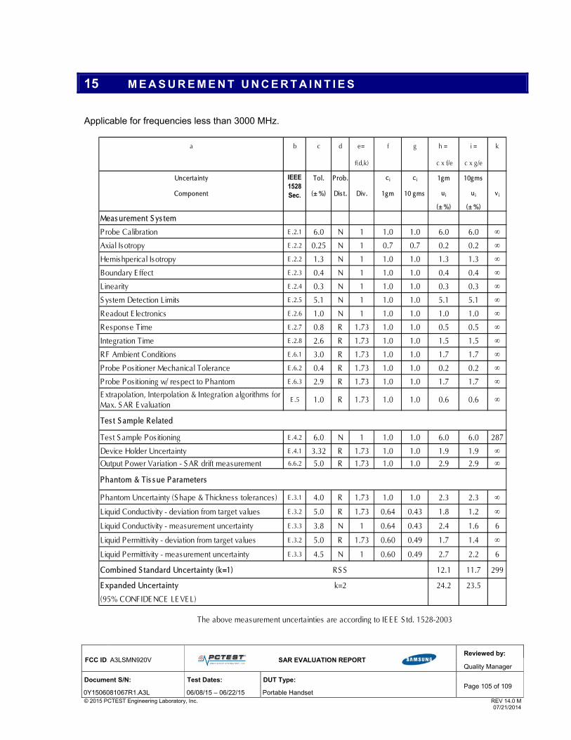
FCC ID: A3LSMN920V
SAR EVALUATION REPORT
Reviewed by:
Quality Manager
Document S/N: Test Dates: DUT Type: Page 105 of 109
0Y1506081067R1.A3L 06/08/15 – 06/22/15 Portable Handset © 2015 PCTEST Engineering Laboratory, Inc. REV 14.0 M 07/21/2014
15 M E A S U R E M E N T U N C E R T A I N T I E S
Applicable for frequencies less than 3000 MHz.
a b c d e= f g h = i = k
f(d,k) c x f/e c x g/e
Uncertainty Tol. Prob. ci ci 1gm 10gms
Component (± %) Dis t. Div. 1gm 10 gms ui ui vi
(± %) (± %)
Meas urement S ys tem
Probe Calibration E .2.1 6.0 N 1 1.0 1.0 6.0 6.0 ∞
Axial Isotropy E .2.2 0.25 N 1 0.7 0.7 0.2 0.2 ∞
Hemishperical Isotropy E .2.2 1.3 N 1 1.0 1.0 1.3 1.3 ∞
Boundary E ffect E .2.3 0.4 N 1 1.0 1.0 0.4 0.4 ∞
Linearity E .2.4 0.3 N 1 1.0 1.0 0.3 0.3 ∞
S ys tem Detection Limits E .2.5 5.1 N 1 1.0 1.0 5.1 5.1 ∞
Readout E lectronics E .2.6 1.0 N 1 1.0 1.0 1.0 1.0 ∞
Response Time E .2.7 0.8 R 1.73 1.0 1.0 0.5 0.5 ∞
Integration Time E .2.8 2.6 R 1.73 1.0 1.0 1.5 1.5 ∞
RF Ambient Conditions E .6.1 3.0 R 1.73 1.0 1.0 1.7 1.7 ∞
Probe Positioner Mechanical Tolerance E .6.2 0.4 R 1.73 1.0 1.0 0.2 0.2 ∞
Probe Positioning w/ respect to Phantom E .6.3 2.9 R 1.73 1.0 1.0 1.7 1.7 ∞
E xtrapolation, Interpolation & Integration algorithms for Max. S AR E valuation
E .5 1.0 R 1.73 1.0 1.0 0.6 0.6 ∞
Tes t S ample Related
Tes t S ample Pos itioning E .4.2 6.0 N 1 1.0 1.0 6.0 6.0 287
Device Holder Uncertainty E .4.1 3.32 R 1.73 1.0 1.0 1.9 1.9 ∞
Output Power Variation - S AR drift measurement 6.6.2 5.0 R 1.73 1.0 1.0 2.9 2.9 ∞
Phantom & Tis s ue Parameters
Phantom Uncertainty (S hape & Thickness tolerances ) E .3.1 4.0 R 1.73 1.0 1.0 2.3 2.3 ∞
Liquid Conductivity - deviation from target values E .3.2 5.0 R 1.73 0.64 0.43 1.8 1.2 ∞
Liquid Conductivity - measurement uncertainty E .3.3 3.8 N 1 0.64 0.43 2.4 1.6 6
Liquid Permittivity - deviation from target values E .3.2 5.0 R 1.73 0.60 0.49 1.7 1.4 ∞
Liquid Permittivity - measurement uncertainty E .3.3 4.5 N 1 0.60 0.49 2.7 2.2 6
Combined S tandard Uncertainty (k=1) RS S 12.1 11.7 299
E xpanded Uncertainty k=2 24.2 23.5
(95% CONFIDE NCE LE VE L)
IEEE 1528 Sec.
The above measurement uncertainties are according to IE E E S td. 1528-2003

FCC ID: A3LSMN920V
SAR EVALUATION REPORT
Reviewed by:
Quality Manager
Document S/N: Test Dates: DUT Type: Page 106 of 109
0Y1506081067R1.A3L 06/08/15 – 06/22/15 Portable Handset © 2015 PCTEST Engineering Laboratory, Inc. REV 14.0 M 07/21/2014
Applicable for frequencies up to 6 GHz.
a b c d e= f g h = i = k
f(d,k) c x f/e c x g/e
Uncertainty Tol. Prob. ci ci 1gm 10gms
Component (± %) Dis t. Div. 1gm 10 gms ui ui vi
(± %) (± %)
Meas urement S ys tem
Probe Calibration E .2.1 6.55 N 1 1.0 1.0 6.6 6.6 ∞
Axial Isotropy E .2.2 0.25 N 1 0.7 0.7 0.2 0.2 ∞
Hemishperical Isotropy E .2.2 1.3 N 1 1.0 1.0 1.3 1.3 ∞
Boundary E ffect E .2.3 0.4 N 1 1.0 1.0 0.4 0.4 ∞
Linearity E .2.4 0.3 N 1 1.0 1.0 0.3 0.3 ∞
S ys tem Detection Limits E .2.5 5.1 N 1 1.0 1.0 5.1 5.1 ∞
Readout E lectronics E .2.6 1.0 N 1 1.0 1.0 1.0 1.0 ∞
Response Time E .2.7 0.8 R 1.73 1.0 1.0 0.5 0.5 ∞
Integration Time E .2.8 2.6 R 1.73 1.0 1.0 1.5 1.5 ∞
RF Ambient Conditions E .6.1 3.0 R 1.73 1.0 1.0 1.7 1.7 ∞
Probe Positioner Mechanical Tolerance E .6.2 0.4 R 1.73 1.0 1.0 0.2 0.2 ∞
Probe Positioning w/ respect to Phantom E .6.3 2.9 R 1.73 1.0 1.0 1.7 1.7 ∞
E xtrapolation, Interpolation & Integration algorithms for Max. S AR E valuation
E .5 1.0 R 1.73 1.0 1.0 0.6 0.6 ∞
Tes t S ample Related
Tes t S ample Pos itioning E .4.2 6.0 N 1 1.0 1.0 6.0 6.0 287
Device Holder Uncertainty E .4.1 3.32 R 1.73 1.0 1.0 1.9 1.9 ∞
Output Power Variation - S AR drift measurement 6.6.2 5.0 R 1.73 1.0 1.0 2.9 2.9 ∞
Phantom & Tis s ue Parameters
Phantom Uncertainty (S hape & Thickness tolerances ) E .3.1 4.0 R 1.73 1.0 1.0 2.3 2.3 ∞
Liquid Conductivity - deviation from target values E .3.2 5.0 R 1.73 0.64 0.43 1.8 1.2 ∞
Liquid Conductivity - measurement uncertainty E .3.3 3.8 N 1 0.64 0.43 2.4 1.6 6
Liquid Permittivity - deviation from target values E .3.2 5.0 R 1.73 0.60 0.49 1.7 1.4 ∞
Liquid Permittivity - measurement uncertainty E .3.3 4.5 N 1 0.60 0.49 2.7 2.2 6
Combined S tandard Uncertainty (k=1) RS S 12.4 12.0 299
E xpanded Uncertainty k=2 24.7 24.0
(95% CONFIDE NCE LE VE L)
IEEE 1528 Sec.
The above measurement uncertainties are according to IE E E S td. 1528-2003

FCC ID: A3LSMN920V
SAR EVALUATION REPORT
Reviewed by:
Quality Manager
Document S/N: Test Dates: DUT Type: Page 107 of 109
0Y1506081067R1.A3L 06/08/15 – 06/22/15 Portable Handset © 2015 PCTEST Engineering Laboratory, Inc. REV 14.0 M 07/21/2014
16 C O N C L U S I O N
16.1 Measurement Conclusion
The SAR evaluation indicates that the EUT complies with the RF radiation exposure limits of the FCC and Industry Canada, with respect to all parameters subject to this test. These measurements were taken to simulate the RF effects of RF exposure under worst-case conditions. Precise laboratory measures were taken to assure repeatability of the tests. The results and statements relate only to the item(s) tested. Please note that the absorption and distribution of electromagnetic energy in the body are very complex phenomena that depend on the mass, shape, and size of the body, the orientation of the body with respect to the field vectors, and the electrical properties of both the body and the environment. Other variables that may play a substantial role in possible biological effects are those that characterize the environment (e.g. ambient temperature, air velocity, relative humidity, and body insulation) and those that characterize the individual (e.g. age, gender, activity level, debilitation, or disease). Because various factors may interact with one another to vary the specific biological outcome of an exposure to electromagnetic fields, any protection guide should consider maximal amplification of biological effects as a result of field-body interactions, environmental conditions, and physiological variables. [3]
FCC ID: A3LSMN920V
SAR EVALUATION REPORT
Reviewed by:
Quality Manager
Document S/N: Test Dates: DUT Type: Page 108 of 109
0Y1506081067R1.A3L 06/08/15 – 06/22/15 Portable Handset © 2015 PCTEST Engineering Laboratory, Inc. REV 14.0 M 07/21/2014
17 R E F E R E N C E S
[1] Federal Communications Commission, ET Docket 93-62, Guidelines for Evaluating the Environmental Effects of
Radiofrequency Radiation, Aug. 1996.
[2] ANSI/IEEE C95.1-2005, American National Standard safety levels with respect to human exposure to radio frequency electromagnetic fields, 3kHz to 300GHz, New York: IEEE, 2006.
[3] ANSI/IEEE C95.1-1992, American National Standard safety levels with respect to human exposure to radio frequency electromagnetic fields, 3kHz to 300GHz, New York: IEEE, Sept. 1992.
[4] ANSI/IEEE C95.3-2002, IEEE Recommended Practice for the Measurement of Potentially Hazardous Electromagnetic Fields - RF and Microwave, New York: IEEE, December 2002.
[5] IEEE Standards Coordinating Committee 39 –Standards Coordinating Committee 34 – IEEE Std. 1528-2003, Recommended Practice for Determining the Peak Spatial-Average Specific Absorption Rate (SAR) in the Human Head Due to Wireless Communications Devices: Measurement Techniques.
[6] NCRP, National Council on Radiation Protection and Measurements, Biological Effects and Exposure Criteria for RadioFrequency Electromagnetic Fields, NCRP Report No. 86, 1986. Reprinted Feb. 1995.
[7] T. Schmid, O. Egger, N. Kuster, Automated E-field scanning system for dosimetric assessments, IEEE Transaction on Microwave Theory and Techniques, vol. 44, Jan. 1996, pp. 105-113.
[8] K. Pokovic, T. Schmid, N. Kuster, Robust setup for precise calibration of E-field probes in tissue simulating liquids at mobile communications frequencies, ICECOM97, Oct. 1997, pp. -124.
[9] K. Pokovic, T. Schmid, and N. Kuster, E-field Probe with improved isotropy in brain simulating liquids, Proceedings of the ELMAR, Zadar, Croatia, June 23-25, 1996, pp. 172-175.
[10] Schmid & Partner Engineering AG, Application Note: Data Storage and Evaluation, June 1998, p2.
[11] V. Hombach, K. Meier, M. Burkhardt, E. Kuhn, N. Kuster, The Dependence of EM Energy Absorption upon Human Modeling at 900 MHz, IEEE Transaction on Microwave Theory and Techniques, vol. 44 no. 10, Oct. 1996, pp. 1865-1873.
[12] N. Kuster and Q. Balzano, Energy absorption mechanism by biological bodies in the near field of dipole antennas above 300MHz, IEEE Transaction on Vehicular Technology, vol. 41, no. 1, Feb. 1992, pp. 17-23.
[13] G. Hartsgrove, A. Kraszewski, A. Surowiec, Simulated Biological Materials for Electromagnetic Radiation Absorption Studies, University of Ottawa, Bioelectromagnetics, Canada: 1987, pp. 29-36.
[14] Q. Balzano, O. Garay, T. Manning Jr., Electromagnetic Energy Exposure of Simulated Users of Portable Cellular Telephones, IEEE Transactions on Vehicular Technology, vol. 44, no.3, Aug. 1995.
[15] W. Gander, Computermathematick, Birkhaeuser, Basel, 1992.
[16] W.H. Press, S.A. Teukolsky, W.T. Vetterling, and B.P. Flannery, Numerical Recipes in C, The Art of Scientific Computing, Second edition, Cambridge University Press, 1992.
[17] N. Kuster, R. Kastle, T. Schmid, Dosimetric evaluation of mobile communications equipment with known precision, IEEE Transaction on Communications, vol. E80-B, no. 5, May 1997, pp. 645-652.

FCC ID: A3LSMN920V
SAR EVALUATION REPORT
Reviewed by:
Quality Manager
Document S/N: Test Dates: DUT Type: Page 109 of 109
0Y1506081067R1.A3L 06/08/15 – 06/22/15 Portable Handset © 2015 PCTEST Engineering Laboratory, Inc. REV 14.0 M 07/21/2014
[18] CENELEC CLC/SC111B, European Prestandard (prENV 50166-2), Human Exposure to Electromagnetic Fields High-frequency: 10kHz-300GHz, Jan. 1995.
[19] Prof. Dr. Niels Kuster, ETH, Eidgenössische Technische Hoschschule Zürich, Dosimetric Evaluation of the Cellular Phone.
[20] IEC 62209-1, Human exposure to radio frequency fields from hand-held and body-mounted wireless communication devices - Human models, instrumentation, and procedures - Part 1: Procedure to determine the specific absorption rate (SAR) for hand-held devices used in close proximity to the ear (frequency range of 300 MHz to 3 GHz), Feb. 2005.
[21] Industry Canada RSS-102 Radio Frequency Exposure Compliance of Radiocommunication Apparatus (All Frequency Bands) Issue 4, March 2010.
[22] Health Canada Safety Code 6 Limits of Human Exposure to Radio Frequency Electromagnetic Fields in the Frequency Range from 3 kHz – 300 GHz, 2009
[23] FCC SAR Test Procedures for 2G-3G Devices, Mobile Hotspot and UMPC Devices KDB Publications 941225, D01-D07
[24] SAR Measurement Guidance for IEEE 802.11 Transmitters, KDB Publication 248227 D01v02r01
[25] FCC SAR Considerations for Handsets with Multiple Transmitters and Antennas, KDB Publications 648474 D03-D04
[26] FCC SAR Evaluation Considerations for Laptop, Notebook, Netbook and Tablet Computers, FCC KDB Publication 616217 D04
[27] FCC SAR Measurement and Reporting Requirements for 100MHz – 6 GHz, KDB Publications 865664 D01-D02
[28] FCC General RF Exposure Guidance and SAR Procedures for Dongles, KDB Publication 447498, D01-D02
[29] Anexo à Resolução No. 533, de 10 de Septembro de 2009.
[30] IEC 62209-2, Human exposure to radio frequency fields from hand-held and body-mounted wireless communication devices - Human models, instrumentation, and procedures - Part 2: Procedure to determine the specific absorption rate (SAR) for wireless communication devices used in close proximity to the human body (frequency range of 30 MHz to 6 GHz), Mar. 2010.

© 2015 PCTEST Engineering Laboratory, Inc.
A P P E N D I X A : S A R T E S T D A T A

A1
PCTEST ENGINEERING LABORATORY, INC.
DUT: A3LSMN920V; Type: Portable Handset; Serial: ADDBE
Communication System: UID 0, GSM; Frequency: 836.6 MHz; Duty Cycle: 1:8.3 Medium: 835 Head Medium parameters used (interpolated): f = 836.6 MHz; σ = 0.896 S/m; εr = 40.207; ρ = 1000 kg/m3
Phantom section: Right Section
Test Date: 06-17-2015; Ambient Temp: 22.7°C; Tissue Temp: 22.0°C
Probe: ES3DV3 - SN3263; ConvF(6.18, 6.18, 6.18); Calibrated: 5/20/2015; Sensor-Surface: 3mm (Mechanical Surface Detection)
Electronics: DAE4 Sn1408; Calibrated: 10/23/2014 Phantom: SAM with CRP v5.0 (Right); Type: QD000P40CD; Serial: TP:1759
Measurement SW: DASY52, Version 52.8 (8); SEMCAD X Version 14.6.10 (7331)
Mode: GSM 850, Right Head, Cheek, Mid.ch
Area Scan (9x14x1): Measurement grid: dx=15mm, dy=15mm Zoom Scan (6x5x7)/Cube 0: Measurement grid: dx=8mm, dy=8mm, dz=5mm
Reference Value = 14.125 V/m; Power Drift = 0.01 dB Peak SAR (extrapolated) = 0.216 W/kg
SAR(1 g) = 0.173 W/kg
0 dB = 0.188 W/kg = -7.26 dBW/kg

A2
PCTEST ENGINEERING LABORATORY, INC.
DUT: A3LSMN920V; Type: Portable Handset; Serial: ADDBE
Communication System: UID 0, GSM1900; Frequency: 1880 MHz; Duty Cycle: 1:8.3 Medium: 1900 Head Medium parameters used:
f = 1880 MHz; σ = 1.379 S/m; εr = 40.4; ρ = 1000 kg/m3 Phantom section: Right Section
Test Date: 06-18-2015; Ambient Temp: 22.7°C; Tissue Temp: 21.9°C
Probe: ES3DV3 - SN3318; ConvF(5.05, 5.05, 5.05); Calibrated: 1/23/2015; Sensor-Surface: 3mm (Mechanical Surface Detection)
Electronics: DAE4 Sn1272; Calibrated: 1/14/2015 Phantom: SAM Front; Type: SAM; Serial: 1686
Measurement SW: DASY52, Version 52.8 (8); SEMCAD X Version 14.6.10 (7331)
Mode: GSM 1900, Right Head, Cheek, Mid.ch
Area Scan (8x14x1): Measurement grid: dx=15mm, dy=15mm Zoom Scan (5x6x7)/Cube 0: Measurement grid: dx=8mm, dy=8mm, dz=5mm
Reference Value = 8.196 V/m; Power Drift = -0.03 dB Peak SAR (extrapolated) = 0.133 W/kg
SAR(1 g) = 0.089 W/kg
0 dB = 0.101 W/kg = -9.96 dBW/kg
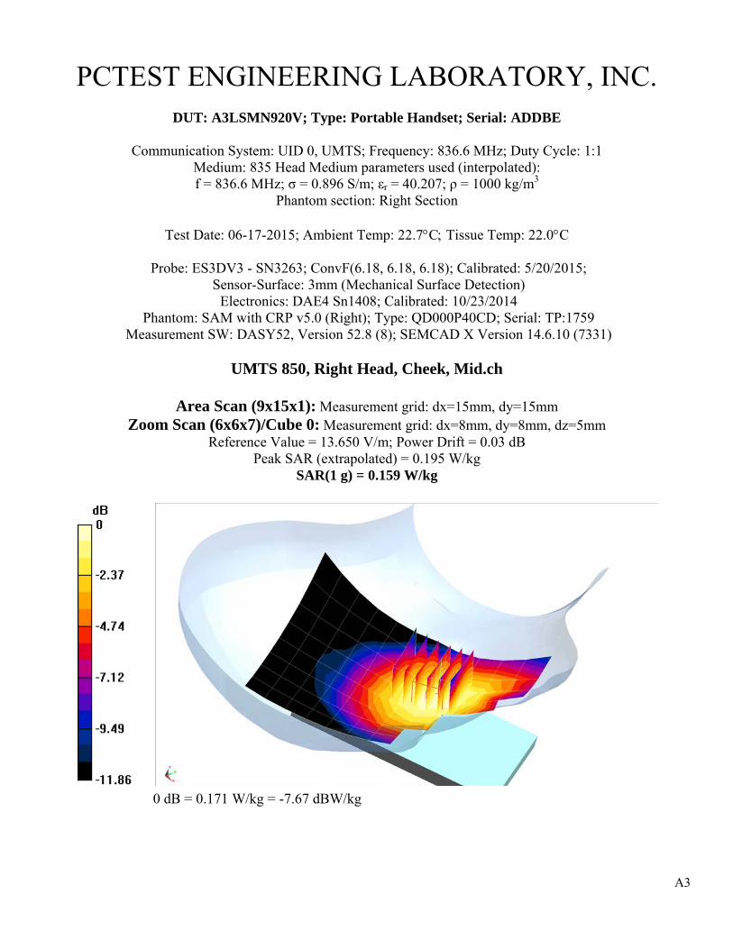
A3
PCTEST ENGINEERING LABORATORY, INC.
DUT: A3LSMN920V; Type: Portable Handset; Serial: ADDBE
Communication System: UID 0, UMTS; Frequency: 836.6 MHz; Duty Cycle: 1:1 Medium: 835 Head Medium parameters used (interpolated): f = 836.6 MHz; σ = 0.896 S/m; εr = 40.207; ρ = 1000 kg/m3
Phantom section: Right Section
Test Date: 06-17-2015; Ambient Temp: 22.7°C; Tissue Temp: 22.0°C
Probe: ES3DV3 - SN3263; ConvF(6.18, 6.18, 6.18); Calibrated: 5/20/2015; Sensor-Surface: 3mm (Mechanical Surface Detection)
Electronics: DAE4 Sn1408; Calibrated: 10/23/2014 Phantom: SAM with CRP v5.0 (Right); Type: QD000P40CD; Serial: TP:1759
Measurement SW: DASY52, Version 52.8 (8); SEMCAD X Version 14.6.10 (7331)
UMTS 850, Right Head, Cheek, Mid.ch
Area Scan (9x15x1): Measurement grid: dx=15mm, dy=15mm Zoom Scan (6x6x7)/Cube 0: Measurement grid: dx=8mm, dy=8mm, dz=5mm
Reference Value = 13.650 V/m; Power Drift = 0.03 dB Peak SAR (extrapolated) = 0.195 W/kg
SAR(1 g) = 0.159 W/kg
0 dB = 0.171 W/kg = -7.67 dBW/kg

A4
PCTEST ENGINEERING LABORATORY, INC.
DUT: A3LSMN920V; Type: Portable Handset; Serial: ADDBE
Communication System: UID 0, UMTS; Frequency: 1880 MHz; Duty Cycle: 1:1 Medium: 1900 Head Medium parameters used:
f = 1880 MHz; σ = 1.395 S/m; εr = 39.656; ρ = 1000 kg/m3 Phantom section: Right Section
Test Date: 06-14-2015; Ambient Temp: 22.5°C; Tissue Temp: 22.0°C
Probe: ES3DV3 - SN3318; ConvF(5.05, 5.05, 5.05); Calibrated: 1/23/2015; Sensor-Surface: 3mm (Mechanical Surface Detection)
Electronics: DAE4 Sn1272; Calibrated: 1/14/2015 Phantom: SAM Front; Type: SAM; Serial: 1686
Measurement SW: DASY52, Version 52.8 (8); SEMCAD X Version 14.6.10 (7331)
Mode: UMTS 1900, Right Head, Cheek, Mid.ch
Area Scan (8x14x1): Measurement grid: dx=15mm, dy=15mm Zoom Scan (5x6x7)/Cube 0: Measurement grid: dx=8mm, dy=8mm, dz=5mm
Reference Value = 11.080 V/m; Power Drift = -0.19 dB Peak SAR (extrapolated) = 0.238 W/kg
SAR(1 g) = 0.155 W/kg
0 dB = 0.177 W/kg = -7.52 dBW/kg

A5
PCTEST ENGINEERING LABORATORY, INC.
DUT: A3LSMN920V; Type: Portable Handset; Serial: AC31E
Communication System: UID 0, CDMA; Frequency: 836.52 MHz; Duty Cycle: 1:1 Medium: 835 Head Medium parameters used (interpolated): f = 836.52 MHz; σ = 0.899 S/m; εr = 40.444; ρ = 1000 kg/m3
Phantom section: Right Section
Test Date: 06-08-2015; Ambient Temp: 22.3°C; Tissue Temp: 21.5°C
Probe: ES3DV3 - SN3288; ConvF(6.51, 6.51, 6.51); Calibrated: 9/24/2014; Sensor-Surface: 3mm (Mechanical Surface Detection)
Electronics: DAE4 Sn1364; Calibrated: 9/18/2014 Phantom: SAM with CRP v4.0; Type: QD000P40CD; Serial: TP:1797
Measurement SW: DASY52, Version 52.8 (8); SEMCAD X Version 14.6.10 (7331)
Mode: Cell. CDMA, Right Head, Cheek, Mid.ch
Area Scan (9x15x1): Measurement grid: dx=15mm, dy=15mm Zoom Scan (5x5x7)/Cube 0: Measurement grid: dx=8mm, dy=8mm, dz=5mm
Reference Value = 14.847 V/m; Power Drift = 0.02 dB Peak SAR (extrapolated) = 0.232 W/kg
SAR(1 g) = 0.185 W/kg
0 dB = 0.199 W/kg = -7.01 dBW/kg
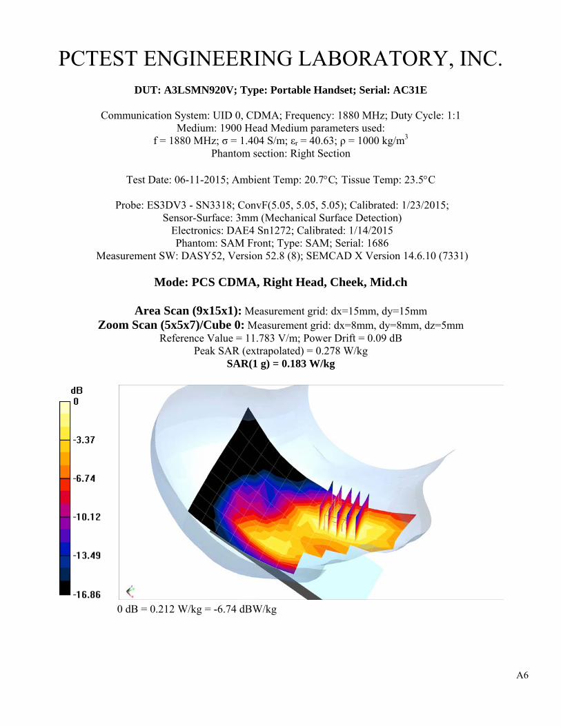
A6
PCTEST ENGINEERING LABORATORY, INC.
DUT: A3LSMN920V; Type: Portable Handset; Serial: AC31E
Communication System: UID 0, CDMA; Frequency: 1880 MHz; Duty Cycle: 1:1 Medium: 1900 Head Medium parameters used:
f = 1880 MHz; σ = 1.404 S/m; εr = 40.63; ρ = 1000 kg/m3 Phantom section: Right Section
Test Date: 06-11-2015; Ambient Temp: 20.7°C; Tissue Temp: 23.5°C
Probe: ES3DV3 - SN3318; ConvF(5.05, 5.05, 5.05); Calibrated: 1/23/2015; Sensor-Surface: 3mm (Mechanical Surface Detection)
Electronics: DAE4 Sn1272; Calibrated: 1/14/2015 Phantom: SAM Front; Type: SAM; Serial: 1686
Measurement SW: DASY52, Version 52.8 (8); SEMCAD X Version 14.6.10 (7331)
Mode: PCS CDMA, Right Head, Cheek, Mid.ch
Area Scan (9x15x1): Measurement grid: dx=15mm, dy=15mm Zoom Scan (5x5x7)/Cube 0: Measurement grid: dx=8mm, dy=8mm, dz=5mm
Reference Value = 11.783 V/m; Power Drift = 0.09 dB Peak SAR (extrapolated) = 0.278 W/kg
SAR(1 g) = 0.183 W/kg
0 dB = 0.212 W/kg = -6.74 dBW/kg

A7
PCTEST ENGINEERING LABORATORY, INC.
DUT: A3LSMN920V; Type: Portable Handset; Serial: AB613
Communication System: UID 0, LTE Band 13; Frequency: 782 MHz; Duty Cycle: 1:1 Medium: 750 Head Medium parameters used (interpolated): f = 782 MHz; σ = 0.924 S/m; εr = 41.604; ρ = 1000 kg/m3
Phantom section: Right Section
Test Date: 06-10-2015; Ambient Temp: 23.4°C; Tissue Temp: 22.1°C
Probe: ES3DV3 - SN3318; ConvF(6.58, 6.58, 6.58); Calibrated: 1/23/2015; Sensor-Surface: 3mm (Mechanical Surface Detection)
Electronics: DAE4 Sn1272; Calibrated: 1/14/2015 Phantom: SAM Front; Type: SAM; Serial: 1686
Measurement SW: DASY52, Version 52.8 (8); SEMCAD X Version 14.6.10 (7331)
Mode: LTE Band 13, Right Head, Cheek, Mid.ch 10 MHz Bandwidth, QPSK, 1 RB, 49 RB Offset
Area Scan (8x13x1): Measurement grid: dx=15mm, dy=15mm
Zoom Scan (5x5x7)/Cube 0: Measurement grid: dx=8mm, dy=8mm, dz=5mm Reference Value = 14.313 V/m; Power Drift = -0.03 dB
Peak SAR (extrapolated) = 0.211 W/kg SAR(1 g) = 0.167 W/kg
0 dB = 0.182 W/kg = -7.40 dBW/kg

A8
PCTEST ENGINEERING LABORATORY, INC.
DUT: A3LSMN920V; Type: Portable Handset; Serial: AB613
Communication System: UID 0, LTE Band 5 (Cell.); Frequency: 836.5 MHz; Duty Cycle: 1:1 Medium: 835 Head Medium parameters used (interpolated): f = 836.5 MHz; σ = 0.899 S/m; εr = 40.444; ρ = 1000 kg/m3
Phantom section: Right Section
Test Date: 06-08-2015; Ambient Temp: 22.3°C; Tissue Temp: 21.5°C
Probe: ES3DV3 - SN3288; ConvF(6.51, 6.51, 6.51); Calibrated: 9/24/2014; Sensor-Surface: 3mm (Mechanical Surface Detection)
Electronics: DAE4 Sn1364; Calibrated: 9/18/2014 Phantom: SAM with CRP v4.0; Type: QD000P40CD; Serial: TP:1797
Measurement SW: DASY52, Version 52.8 (8); SEMCAD X Version 14.6.10 (7331)
Mode: LTE Band 5 (Cell.), Right Head, Cheek, Mid.ch, 10 MHz Bandwidth, QPSK, 1 RB, 49 RB Offset
Area Scan (9x15x1): Measurement grid: dx=15mm, dy=15mm
Zoom Scan (6x5x7)/Cube 0: Measurement grid: dx=8mm, dy=8mm, dz=5mm Reference Value = 13.045 V/m; Power Drift = 0.05 dB
Peak SAR (extrapolated) = 0.160 W/kg SAR(1 g) = 0.132 W/kg
0 dB = 0.142 W/kg = -8.48 dBW/kg

A9
PCTEST ENGINEERING LABORATORY, INC.
DUT: A3LSMN920V; Type: Portable Handset; Serial: AB613
Communication System: UID 0, LTE RF Band 4; Frequency: 1732.5 MHz; Duty Cycle: 1:1 Medium: 1750 Head Medium parameters used (interpolated): f = 1732.5 MHz; σ = 1.333 S/m; εr = 39.168; ρ = 1000 kg/m3
Phantom section: Right Section
Test Date: 06-12-2015; Ambient Temp: 22.7°C; Tissue Temp: 22.9°C
Probe: ES3DV3 - SN3288; ConvF(5.38, 5.38, 5.38); Calibrated: 9/24/2014; Sensor-Surface: 3mm (Mechanical Surface Detection)
Electronics: DAE4 Sn1364; Calibrated: 9/18/2014 Phantom: SAM with CRP v4.0; Type: QD000P40CD; Serial: TP:1797
Measurement SW: DASY52, Version 52.8 (8); SEMCAD X Version 14.6.10 (7331)
Mode: LTE Band 4 (AWS), Right Head, Cheek, Mid.ch 20 MHz Bandwidth, QPSK, 1 RB, 0 RB Offset
Area Scan (9x15x1): Measurement grid: dx=15mm, dy=15mm
Zoom Scan (5x5x7)/Cube 0: Measurement grid: dx=8mm, dy=8mm, dz=5mm Reference Value = 12.159 V/m; Power Drift = 0.00 dB
Peak SAR (extrapolated) = 0.231 W/kg SAR(1 g) = 0.160 W/kg
0 dB = 0.185 W/kg = -7.33 dBW/kg

A10
PCTEST ENGINEERING LABORATORY, INC.
DUT: A3LSMN920V; Type: Portable Handset; Serial: AB613
Communication System: UID 0, LTE Band 2 (PCS); Frequency: 1880 MHz; Duty Cycle: 1:1 Medium: 1900 Head Medium parameters used:
f = 1880 MHz; σ = 1.404 S/m; εr = 40.63; ρ = 1000 kg/m3 Phantom section: Right Section
Test Date: 06-11-2015; Ambient Temp: 20.7°C; Tissue Temp: 23.5°C
Probe: ES3DV3 - SN3318; ConvF(5.05, 5.05, 5.05); Calibrated: 1/23/2015; Sensor-Surface: 3mm (Mechanical Surface Detection)
Electronics: DAE4 Sn1272; Calibrated: 1/14/2015 Phantom: SAM Front; Type: SAM; Serial: 1686
Measurement SW: DASY52, Version 52.8 (8); SEMCAD X Version 14.6.10 (7331)
Mode: LTE Band 2 (PCS), Right Head, Cheek, Mid.ch 20 MHz Bandwidth, QPSK, 1 RB, 0 RB Offset
Area Scan (9x15x1): Measurement grid: dx=15mm, dy=15mm
Zoom Scan (5x5x7)/Cube 0: Measurement grid: dx=8mm, dy=8mm, dz=5mm Reference Value = 11.986 V/m; Power Drift = 0.03 dB
Peak SAR (extrapolated) = 0.245 W/kg SAR(1 g) = 0.162 W/kg
0 dB = 0.187 W/kg = -7.28 dBW/kg
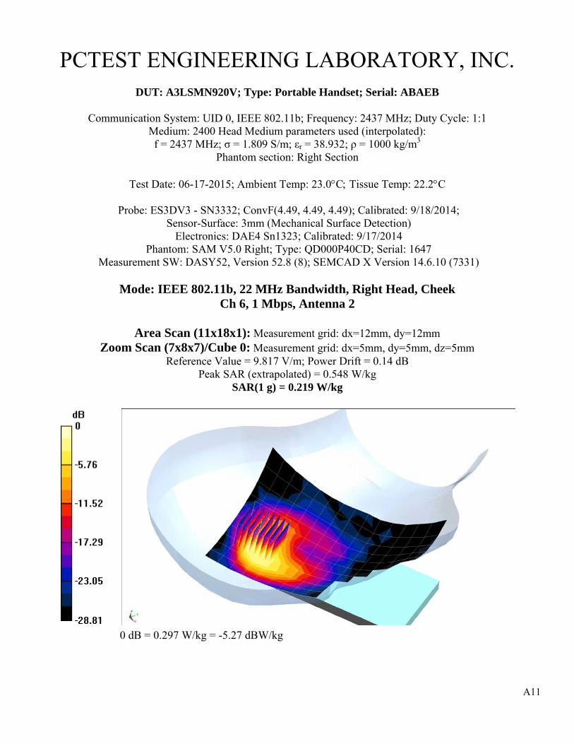
A11
PCTEST ENGINEERING LABORATORY, INC.
DUT: A3LSMN920V; Type: Portable Handset; Serial: ABAEB
Communication System: UID 0, IEEE 802.11b; Frequency: 2437 MHz; Duty Cycle: 1:1 Medium: 2400 Head Medium parameters used (interpolated): f = 2437 MHz; σ = 1.809 S/m; εr = 38.932; ρ = 1000 kg/m3
Phantom section: Right Section
Test Date: 06-17-2015; Ambient Temp: 23.0°C; Tissue Temp: 22.2°C
Probe: ES3DV3 - SN3332; ConvF(4.49, 4.49, 4.49); Calibrated: 9/18/2014; Sensor-Surface: 3mm (Mechanical Surface Detection)
Electronics: DAE4 Sn1323; Calibrated: 9/17/2014 Phantom: SAM V5.0 Right; Type: QD000P40CD; Serial: 1647
Measurement SW: DASY52, Version 52.8 (8); SEMCAD X Version 14.6.10 (7331)
Mode: IEEE 802.11b, 22 MHz Bandwidth, Right Head, Cheek Ch 6, 1 Mbps, Antenna 2
Area Scan (11x18x1): Measurement grid: dx=12mm, dy=12mm
Zoom Scan (7x8x7)/Cube 0: Measurement grid: dx=5mm, dy=5mm, dz=5mm Reference Value = 9.817 V/m; Power Drift = 0.14 dB
Peak SAR (extrapolated) = 0.548 W/kg SAR(1 g) = 0.219 W/kg
0 dB = 0.297 W/kg = -5.27 dBW/kg

A12
PCTEST ENGINEERING LABORATORY, INC.
DUT: A3LSMN920V; Type: Portable Handset; Serial: ABAEB
Communication System: UID 0, IEEE 802.11a; Frequency: 5500 MHz; Duty Cycle: 1:1 Medium: 5 GHz Head Medium parameters used:
f = 5500 MHz; σ = 4.95 S/m; εr = 34.051; ρ = 1000 kg/m3 Phantom section: Right Section
Test Date: 06-15-2015; Ambient Temp: 22.5°C; Tissue Temp: 21.6°C
Probe: EX3DV4 - SN7357; ConvF(4.7, 4.7, 4.7); Calibrated: 4/23/2015; Sensor-Surface: 1.4mm (Mechanical Surface Detection)
Electronics: DAE4 Sn1334; Calibrated: 3/13/2015 Phantom: SAM v5.0 front; Type: QD000P40CD; Serial: TP-1646
Measurement SW: DASY52, Version 52.8 (8); SEMCAD X Version 14.6.10 (7331)
Mode: IEEE 802.11a, U-NII 2C, 20 MHz Bandwidth, Right Head, Cheek Ch 100, 6 Mbps, Antenna 1
Area Scan (13x9x1): Measurement grid: dx=10mm, dy=10mm
Zoom Scan (7x8x7)/Cube 0: Measurement grid: dx=4mm, dy=4mm, dz=1.4mm; Graded Ratio =1.4 Reference Value = 12.968 V/m; Power Drift = 0.03 dB
Peak SAR (extrapolated) = 3.49 W/kg SAR(1 g) = 0.657 W/kg
0 dB = 1.33 W/kg = 1.24 dBW/kg

A13
PCTEST ENGINEERING LABORATORY, INC.
DUT: A3LSMN920V; Type: Portable Handset; Serial: ADDBE
Communication System: UID 0, GSM; Frequency: 836.6 MHz; Duty Cycle: 1:8.3 Medium: 835 Body Medium parameters used (interpolated): f = 836.6 MHz; σ = 0.99 S/m; εr = 52.854; ρ = 1000 kg/m3
Phantom section: Flat Section; Space: 1.5 cm
Test Date: 06-22-2015; Ambient Temp: 22.7°C; Tissue Temp: 21.4°C
Probe: ES3DV3 - SN3318; ConvF(6.23, 6.23, 6.23); Calibrated: 1/23/2015; Sensor-Surface: 3mm (Mechanical Surface Detection)
Electronics: DAE4 Sn1272; Calibrated: 1/14/2015 Phantom: ELI v6.0; Type: QDOVA003AA; Serial: TP:2027
Measurement SW: DASY52, Version 52.8 (8); SEMCAD X Version 14.6.10 (7331)
Mode: GSM 850, Body SAR, Back side, Mid.ch
Area Scan (9x15x1): Measurement grid: dx=15mm, dy=15mm Zoom Scan (5x5x7)/Cube 0: Measurement grid: dx=8mm, dy=8mm, dz=5mm
Reference Value = 20.522 V/m; Power Drift = -0.06 dB Peak SAR (extrapolated) = 0.518 W/kg
SAR(1 g) = 0.385 W/kg
0 dB = 0.430 W/kg = -3.67 dBW/kg
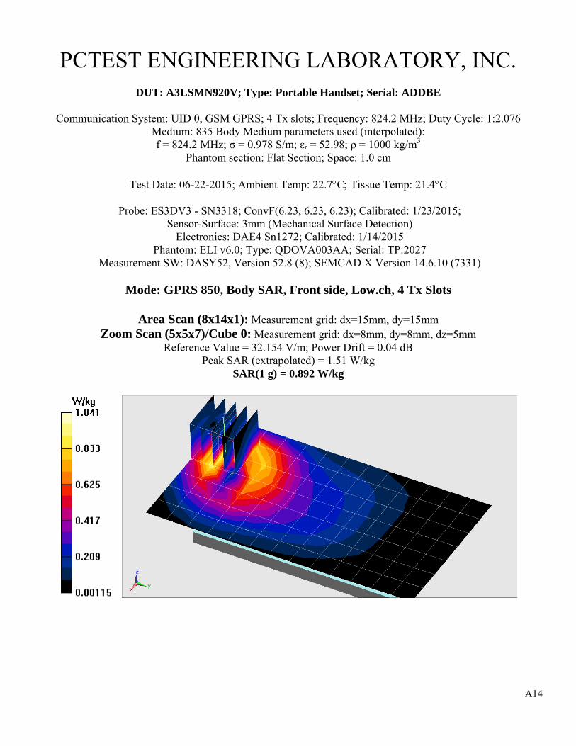
A14
PCTEST ENGINEERING LABORATORY, INC.
DUT: A3LSMN920V; Type: Portable Handset; Serial: ADDBE
Communication System: UID 0, GSM GPRS; 4 Tx slots; Frequency: 824.2 MHz; Duty Cycle: 1:2.076 Medium: 835 Body Medium parameters used (interpolated): f = 824.2 MHz; σ = 0.978 S/m; εr = 52.98; ρ = 1000 kg/m3
Phantom section: Flat Section; Space: 1.0 cm
Test Date: 06-22-2015; Ambient Temp: 22.7°C; Tissue Temp: 21.4°C
Probe: ES3DV3 - SN3318; ConvF(6.23, 6.23, 6.23); Calibrated: 1/23/2015; Sensor-Surface: 3mm (Mechanical Surface Detection)
Electronics: DAE4 Sn1272; Calibrated: 1/14/2015 Phantom: ELI v6.0; Type: QDOVA003AA; Serial: TP:2027
Measurement SW: DASY52, Version 52.8 (8); SEMCAD X Version 14.6.10 (7331)
Mode: GPRS 850, Body SAR, Front side, Low.ch, 4 Tx Slots
Area Scan (8x14x1): Measurement grid: dx=15mm, dy=15mm Zoom Scan (5x5x7)/Cube 0: Measurement grid: dx=8mm, dy=8mm, dz=5mm
Reference Value = 32.154 V/m; Power Drift = 0.04 dB Peak SAR (extrapolated) = 1.51 W/kg
SAR(1 g) = 0.892 W/kg

A15
PCTEST ENGINEERING LABORATORY, INC.
DUT: A3LSMN920V; Type: Portable Handset; Serial: ADDBE
Communication System: UID 0, GSM; Frequency: 1880 MHz; Duty Cycle: 1:8.3 Medium: 1900 Body Medium parameters used:
f = 1880 MHz; σ = 1.518 S/m; εr = 51.673; ρ = 1000 kg/m3 Phantom section: Flat Section; 1.5 cm
Test Date: 06-18-2015; Ambient Temp: 22.0°C; Tissue Temp: 22.0°C
Probe: ES3DV3 - SN3263; ConvF(4.66, 4.66, 4.66); Calibrated: 5/20/2015; Sensor-Surface: 3mm (Mechanical Surface Detection)
Electronics: DAE4 Sn1408; Calibrated: 10/23/2014 Phantom: SAM with CRP (Left); Type: SAM; Serial: 1715
Measurement SW: DASY52, Version 52.8 (8); SEMCAD X Version 14.6.10 (7331)
Mode: GSM 1900, Body SAR, Back side, Mid.ch
Area Scan (9x15x1): Measurement grid: dx=15mm, dy=15mm Zoom Scan (5x5x7)/Cube 0: Measurement grid: dx=8mm, dy=8mm, dz=5mm
Reference Value = 13.853 V/m; Power Drift = 0.00 dB Peak SAR (extrapolated) = 0.417 W/kg
SAR(1 g) = 0.263 W/kg
0 dB = 0.316 W/kg = -5.00 dBW/kg

A16
PCTEST ENGINEERING LABORATORY, INC.
DUT: A3LSMN920V; Type: Portable Handset; Serial: ADFB5
Communication System: UID 0, GSM GPRS; 4 Tx slots; Frequency: 1909.8 MHz; Duty Cycle: 1:2.076 Medium: 1900 Body Medium parameters used:
f = 1910 MHz; σ = 1.56 S/m; εr = 52.026; ρ = 1000 kg/m3 Phantom section: Flat Section; Space: 1.0 cm
Test Date: 06-22-2015; Ambient Temp: 20.7°C; Tissue Temp: 21.7°C
Probe: ES3DV3 - SN3263; ConvF(4.66, 4.66, 4.66); Calibrated: 5/20/2015; Sensor-Surface: 3mm (Mechanical Surface Detection)
Electronics: DAE4 Sn1408; Calibrated: 10/23/2014 Phantom: SAM with CRP (Left); Type: SAM; Serial: 1715
Measurement SW: DASY52, Version 52.8 (8); SEMCAD X Version 14.6.10 (7331)
Mode: GPRS 1900, Body SAR, Bottom Edge, High.ch, 4 Tx Slots
Area Scan (13x9x1): Measurement grid: dx=5mm, dy=15mm Zoom Scan (5x5x7)/Cube 0: Measurement grid: dx=8mm, dy=8mm, dz=5mm
Reference Value = 28.283 V/m; Power Drift = -0.06 dB Peak SAR (extrapolated) = 1.75 W/kg
SAR(1 g) = 1.06 W/kg
0 dB = 1.30 W/kg = 1.14 dBW/kg

A17
PCTEST ENGINEERING LABORATORY, INC.
DUT: A3LSMN920V; Type: Portable Handset; Serial: ADDBE
Communication System: UID 0, UMTS; Frequency: 836.6 MHz; Duty Cycle: 1:1 Medium: 835 Body Medium parameters used (interpolated): f = 836.6 MHz; σ = 1.002 S/m; εr = 53.897; ρ = 1000 kg/m3
Phantom section: Flat Section; Space: 1.5 cm
Test Date: 06-13-2015; Ambient Temp: 23.2°C; Tissue Temp: 21.8°C
Probe: ES3DV3 - SN3318; ConvF(6.23, 6.23, 6.23); Calibrated: 1/23/2015; Sensor-Surface: 3mm (Mechanical Surface Detection)
Electronics: DAE4 Sn1272; Calibrated: 1/14/2015 Phantom: ELI v6.0; Type: QDOVA003AA; Serial: TP:2027
Measurement SW: DASY52, Version 52.8 (8); SEMCAD X Version 14.6.10 (7331)
Mode: UMTS 850, Body SAR, Back side, Mid.ch
Area Scan (9x15x1): Measurement grid: dx=15mm, dy=15mm Zoom Scan (5x5x7)/Cube 0: Measurement grid: dx=8mm, dy=8mm, dz=5mm
Reference Value = 18.234 V/m; Power Drift = -0.01 dB Peak SAR (extrapolated) = 0.415 W/kg
SAR(1 g) = 0.309 W/kg
0 dB = 0.342 W/kg = -4.66 dBW/kg

A18
PCTEST ENGINEERING LABORATORY, INC.
DUT: A3LSMN920V; Type: Portable Handset; Serial: ADDBE
Communication System: UID 0, UMTS; Frequency: 836.6 MHz; Duty Cycle: 1:1 Medium: 835 Body Medium parameters used (interpolated): f = 836.6 MHz; σ = 1.002 S/m; εr = 53.897; ρ = 1000 kg/m3
Phantom section: Flat Section; Space: 1.0 cm
Test Date: 06-13-2015; Ambient Temp: 23.2°C; Tissue Temp: 21.8°C
Probe: ES3DV3 - SN3318; ConvF(6.23, 6.23, 6.23); Calibrated: 1/23/2015; Sensor-Surface: 3mm (Mechanical Surface Detection)
Electronics: DAE4 Sn1272; Calibrated: 1/14/2015 Phantom: ELI v6.0; Type: QDOVA003AA; Serial: TP:2027
Measurement SW: DASY52, Version 52.8 (8); SEMCAD X Version 14.6.10 (7331)
Mode: UMTS 850, Body SAR, Back side, Mid.ch
Area Scan (9x15x1): Measurement grid: dx=15mm, dy=15mm Zoom Scan (6x6x7)/Cube 0: Measurement grid: dx=8mm, dy=8mm, dz=5mm
Reference Value = 22.987 V/m; Power Drift = -0.04 dB Peak SAR (extrapolated) = 0.881 W/kg
SAR(1 g) = 0.515 W/kg
0 dB = 0.627 W/kg = -2.03 dBW/kg

A19
PCTEST ENGINEERING LABORATORY, INC.
DUT: A3LSMN920V; Type: Portable Handset; Serial: ADDBE
Communication System: UID 0, UMTS; Frequency: 1880 MHz; Duty Cycle: 1:1 Medium: 1900 Body Medium parameters used:
f = 1880 MHz; σ = 1.54 S/m; εr = 52.457; ρ = 1000 kg/m3 Phantom section: Flat Section; Space: 1.5 cm
Test Date: 06-13-2015; Ambient Temp: 21.3°C; Tissue Temp: 21.3°C
Probe: ES3DV3 - SN3263; ConvF(4.66, 4.66, 4.66); Calibrated: 5/20/2015; Sensor-Surface: 3mm (Mechanical Surface Detection)
Electronics: DAE4 Sn1408; Calibrated: 10/23/2014 Phantom: SAM with CRP (Left); Type: SAM; Serial: 1715
Measurement SW: DASY52, Version 52.8 (8); SEMCAD X Version 14.6.10 (7331)
Mode: UMTS 1900, Body SAR, Back side, Mid.ch
Area Scan (9x14x1): Measurement grid: dx=15mm, dy=15mm Zoom Scan (5x5x7)/Cube 0: Measurement grid: dx=8mm, dy=8mm, dz=5mm
Reference Value = 17.402 V/m; Power Drift = 0.00 dB Peak SAR (extrapolated) = 0.718 W/kg
SAR(1 g) = 0.461 W/kg
0 dB = 0.540 W/kg = -2.68 dBW/kg
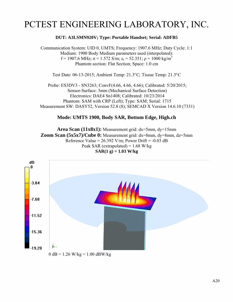
A20
PCTEST ENGINEERING LABORATORY, INC.
DUT: A3LSMN920V; Type: Portable Handset; Serial: ADFB5
Communication System: UID 0, UMTS; Frequency: 1907.6 MHz; Duty Cycle: 1:1 Medium: 1900 Body Medium parameters used (interpolated): f = 1907.6 MHz; σ = 1.572 S/m; εr = 52.351; ρ = 1000 kg/m3
Phantom section: Flat Section; Space: 1.0 cm
Test Date: 06-13-2015; Ambient Temp: 21.3°C; Tissue Temp: 21.3°C
Probe: ES3DV3 - SN3263; ConvF(4.66, 4.66, 4.66); Calibrated: 5/20/2015; Sensor-Surface: 3mm (Mechanical Surface Detection)
Electronics: DAE4 Sn1408; Calibrated: 10/23/2014 Phantom: SAM with CRP (Left); Type: SAM; Serial: 1715
Measurement SW: DASY52, Version 52.8 (8); SEMCAD X Version 14.6.10 (7331)
Mode: UMTS 1900, Body SAR, Bottom Edge, High.ch
Area Scan (11x8x1): Measurement grid: dx=5mm, dy=15mm Zoom Scan (5x5x7)/Cube 0: Measurement grid: dx=8mm, dy=8mm, dz=5mm
Reference Value = 26.392 V/m; Power Drift = -0.03 dB Peak SAR (extrapolated) = 1.68 W/kg
SAR(1 g) = 1.03 W/kg
0 dB = 1.26 W/kg = 1.00 dBW/kg

A21
PCTEST ENGINEERING LABORATORY, INC.
DUT: A3LSMN920V; Type: Portable Handset; Serial: AC31E
Communication System: UID 0, CDMA; Frequency: 836.52 MHz; Duty Cycle: 1:1 Medium: 835 Body Medium parameters used (interpolated): f = 836.52 MHz; σ = 0.983 S/m; εr = 54.048; ρ = 1000 kg/m3
Phantom section: Flat Section; Space: 1.5 cm
Test Date: 06-10-2015; Ambient Temp: 23.3°C; Tissue Temp: 21.9°C
Probe: ES3DV3 - SN3288; ConvF(6.32, 6.32, 6.32); Calibrated: 9/24/2014; Sensor-Surface: 3mm (Mechanical Surface Detection)
Electronics: DAE4 Sn1364; Calibrated: 9/18/2014 Phantom: ELI v5.0; Type: QDOVA001BB; Serial: 1229
Measurement SW: DASY52, Version 52.8 (8); SEMCAD X Version 14.6.10 (7331)
Mode: Cell. CDMA, Body SAR, Back side, Mid.ch
Area Scan (9x15x1): Measurement grid: dx=15mm, dy=15mm Zoom Scan (5x5x7)/Cube 0: Measurement grid: dx=8mm, dy=8mm, dz=5mm
Reference Value = 22.281 V/m; Power Drift = 0.03 dB Peak SAR (extrapolated) = 0.613 W/kg
SAR(1 g) = 0.450 W/kg
0 dB = 0.505 W/kg = -2.97 dBW/kg

A22
PCTEST ENGINEERING LABORATORY, INC.
DUT: A3LSMN920V; Type: Portable Handset; Serial: AC31E
Communication System: UID 0, CDMA; Frequency: 836.52 MHz; Duty Cycle: 1:1 Medium: 835 Body Medium parameters used (interpolated): f = 836.52 MHz; σ = 0.983 S/m; εr = 54.048; ρ = 1000 kg/m3
Phantom section: Flat Section; Space: 1.0 cm
Test Date: 06-10-2015; Ambient Temp: 23.3°C; Tissue Temp: 21.9°C
Probe: ES3DV3 - SN3288; ConvF(6.32, 6.32, 6.32); Calibrated: 9/24/2014; Sensor-Surface: 3mm (Mechanical Surface Detection)
Electronics: DAE4 Sn1364; Calibrated: 9/18/2014 Phantom: ELI v5.0; Type: QDOVA001BB; Serial: 1229
Measurement SW: DASY52, Version 52.8 (8); SEMCAD X Version 14.6.10 (7331)
Mode: Cell. EVDO Rev.0, Body SAR, Front side, Mid.ch
Area Scan (9x15x1): Measurement grid: dx=15mm, dy=15mm Zoom Scan (5x5x7)/Cube 0: Measurement grid: dx=8mm, dy=8mm, dz=5mm
Reference Value = 31.781 V/m; Power Drift = -0.04 dB Peak SAR (extrapolated) = 1.48 W/kg
SAR(1 g) = 0.875 W/kg
0 dB = 1.07 W/kg = 0.29 dBW/kg
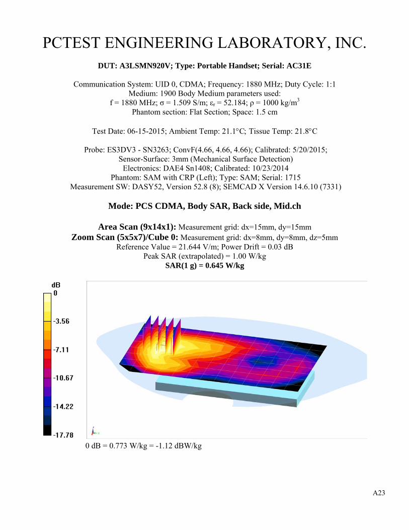
A23
PCTEST ENGINEERING LABORATORY, INC.
DUT: A3LSMN920V; Type: Portable Handset; Serial: AC31E
Communication System: UID 0, CDMA; Frequency: 1880 MHz; Duty Cycle: 1:1 Medium: 1900 Body Medium parameters used:
f = 1880 MHz; σ = 1.509 S/m; εr = 52.184; ρ = 1000 kg/m3 Phantom section: Flat Section; Space: 1.5 cm
Test Date: 06-15-2015; Ambient Temp: 21.1°C; Tissue Temp: 21.8°C
Probe: ES3DV3 - SN3263; ConvF(4.66, 4.66, 4.66); Calibrated: 5/20/2015; Sensor-Surface: 3mm (Mechanical Surface Detection)
Electronics: DAE4 Sn1408; Calibrated: 10/23/2014 Phantom: SAM with CRP (Left); Type: SAM; Serial: 1715
Measurement SW: DASY52, Version 52.8 (8); SEMCAD X Version 14.6.10 (7331)
Mode: PCS CDMA, Body SAR, Back side, Mid.ch
Area Scan (9x14x1): Measurement grid: dx=15mm, dy=15mm Zoom Scan (5x5x7)/Cube 0: Measurement grid: dx=8mm, dy=8mm, dz=5mm
Reference Value = 21.644 V/m; Power Drift = 0.03 dB Peak SAR (extrapolated) = 1.00 W/kg
SAR(1 g) = 0.645 W/kg
0 dB = 0.773 W/kg = -1.12 dBW/kg

A24
PCTEST ENGINEERING LABORATORY, INC.
DUT: A3LSMN920V; Type: Portable Handset; Serial: AD7EC
Communication System: UID 0, CDMA; Frequency: 1908.75 MHz; Duty Cycle: 1:1 Medium: 1900 Body Medium parameters used (interpolated): f = 1908.75 MHz; σ = 1.559 S/m; εr = 52.031; ρ = 1000 kg/m3
Phantom section: Flat Section; Space: 1.0 cm
Test Date: 06-22-2015; Ambient Temp: 20.7°C; Tissue Temp: 21.7°C
Probe: ES3DV3 - SN3263; ConvF(4.66, 4.66, 4.66); Calibrated: 5/20/2015; Sensor-Surface: 3mm (Mechanical Surface Detection)
Electronics: DAE4 Sn1408; Calibrated: 10/23/2014 Phantom: SAM with CRP (Left); Type: SAM; Serial: 1715
Measurement SW: DASY52, Version 52.8 (8); SEMCAD X Version 14.6.10 (7331)
Mode: PCS EVDO Rev.0, Body SAR, Bottom Edge, High.ch
Area Scan (13x9x1): Measurement grid: dx=5mm, dy=15mm Zoom Scan (5x5x7)/Cube 0: Measurement grid: dx=8mm, dy=8mm, dz=5mm
Reference Value = 26.381 V/m; Power Drift = 0.01 dB Peak SAR (extrapolated) = 1.54 W/kg
SAR(1 g) = 0.934 W/kg
0 dB = 1.15 W/kg = 0.61 dBW/kg

A25
PCTEST ENGINEERING LABORATORY, INC.
DUT: A3LSMN920V; Type: Portable Handset; Serial: AB613
Communication System: UID 0, LTE Band 13; Frequency: 782 MHz; Duty Cycle: 1:1 Medium: 750 Body Medium parameters used (interpolated):
f = 782 MHz; σ = 0.995 S/m; εr = 54.55; ρ = 1000 kg/m3 Phantom section: Flat Section; Space: 1.5 cm
Test Date: 06-16-2015; Ambient Temp: 24.8°C; Tissue Temp: 23.0°C
Probe: ES3DV3 - SN3263; ConvF(6.07, 6.07, 6.07); Calibrated: 5/20/2015; Sensor-Surface: 3mm (Mechanical Surface Detection)
Electronics: DAE4 Sn1408; Calibrated: 10/23/2014 Phantom: SAM with CRP v5.0 (Right); Type: QD000P40CD; Serial: TP:1759
Measurement SW: DASY52, Version 52.8 (8); SEMCAD X Version 14.6.10 (7331)
Mode: LTE Band 13, Body SAR, Back side, Mid.ch 10 MHz Bandwidth, QPSK, 1 RB, 49 RB Offset
Area Scan (9x13x1): Measurement grid: dx=15mm, dy=15mm
Zoom Scan (5x5x7)/Cube 0: Measurement grid: dx=8mm, dy=8mm, dz=5mm Reference Value = 20.016 V/m; Power Drift = 0.11 dB
Peak SAR (extrapolated) = 0.520 W/kg SAR(1 g) = 0.381 W/kg
0 dB = 0.429 W/kg = -3.68 dBW/kg

A26
PCTEST ENGINEERING LABORATORY, INC.
DUT: A3LSMN920V; Type: Portable Handset; Serial: AB613
Communication System: UID 0, LTE Band 13; Frequency: 782 MHz; Duty Cycle: 1:1 Medium: 750 Body Medium parameters used (interpolated):
f = 782 MHz; σ = 0.995 S/m; εr = 54.55; ρ = 1000 kg/m3 Phantom section: Flat Section; Space: 1.0 cm
Test Date: 06-16-2015; Ambient Temp: 24.8°C; Tissue Temp: 23.0°C
Probe: ES3DV3 - SN3263; ConvF(6.07, 6.07, 6.07); Calibrated: 5/20/2015; Sensor-Surface: 3mm (Mechanical Surface Detection)
Electronics: DAE4 Sn1408; Calibrated: 10/23/2014 Phantom: SAM with CRP v5.0 (Right); Type: QD000P40CD; Serial: TP:1759
Measurement SW: DASY52, Version 52.8 (8); SEMCAD X Version 14.6.10 (7331)
Mode: LTE Band 13, Body SAR, Front side, Mid.ch 10 MHz Bandwidth, QPSK, 1 RB, 49 RB Offset
Area Scan (9x13x1): Measurement grid: dx=15mm, dy=15mm
Zoom Scan (5x5x7)/Cube 0: Measurement grid: dx=8mm, dy=8mm, dz=5mm Reference Value = 26.264 V/m; Power Drift = -0.09 dB
Peak SAR (extrapolated) = 1.06 W/kg SAR(1 g) = 0.623 W/kg

A27
PCTEST ENGINEERING LABORATORY, INC.
DUT: A3LSMN920V; Type: Portable Handset; Serial: AB613
Communication System: UID 0, LTE Band 5; Frequency: 836.5 MHz; Duty Cycle: 1:1 Medium: 835 Body Medium parameters used (interpolated): f = 836.5 MHz; σ = 0.983 S/m; εr = 54.048; ρ = 1000 kg/m3
Phantom section: Flat Section; Space: 1.5 cm
Test Date: 06-10-2015; Ambient Temp: 23.3°C; Tissue Temp: 21.9°C
Probe: ES3DV3 - SN3288; ConvF(6.32, 6.32, 6.32); Calibrated: 9/24/2014; Sensor-Surface: 3mm (Mechanical Surface Detection)
Electronics: DAE4 Sn1364; Calibrated: 9/18/2014 Phantom: ELI v5.0; Type: QDOVA001BB; Serial: 1229
Measurement SW: DASY52, Version 52.8 (8); SEMCAD X Version 14.6.10 (7331)
Mode: LTE Band 5 (Cell.), Body SAR, Back side, Mid.ch 10 MHz Bandwidth, QPSK, 1 RB, 49 RB Offset
Area Scan (9x15x1): Measurement grid: dx=15mm, dy=15mm
Zoom Scan (5x5x7)/Cube 0: Measurement grid: dx=8mm, dy=8mm, dz=5mm Reference Value = 18.167 V/m; Power Drift = -0.01 dB
Peak SAR (extrapolated) = 0.453 W/kg SAR(1 g) = 0.327 W/kg
0 dB = 0.369 W/kg = -4.33 dBW/kg

A28
PCTEST ENGINEERING LABORATORY, INC.
DUT: A3LSMN920V; Type: Portable Handset; Serial: AB613
Communication System: UID 0, LTE Band 5 (Cell.); Frequency: 836.5 MHz; Duty Cycle: 1:1 Medium: 835 Body Medium parameters used (interpolated): f = 836.5 MHz; σ = 0.983 S/m; εr = 54.048; ρ = 1000 kg/m3
Phantom section: Flat Section; Space: 1.0 cm
Test Date: 06-10-2015; Ambient Temp: 23.3°C; Tissue Temp: 21.9°C
Probe: ES3DV3 - SN3288; ConvF(6.32, 6.32, 6.32); Calibrated: 9/24/2014; Sensor-Surface: 3mm (Mechanical Surface Detection)
Electronics: DAE4 Sn1364; Calibrated: 9/18/2014 Phantom: ELI v5.0; Type: QDOVA001BB; Serial: 1229
Measurement SW: DASY52, Version 52.8 (8); SEMCAD X Version 14.6.10 (7331)
Mode: LTE Band 5 (Cell.), Body SAR, Front side, Mid.ch 10 MHz Bandwidth, QPSK, 1 RB, 49 RB Offset
Area Scan (9x15x1): Measurement grid: dx=15mm, dy=15mm
Zoom Scan (5x5x7)/Cube 0: Measurement grid: dx=8mm, dy=8mm, dz=5mm Reference Value = 25.417 V/m; Power Drift = 0.05 dB
Peak SAR (extrapolated) = 1.05 W/kg SAR(1 g) = 0.616 W/kg
0 dB = 0.732 W/kg = -1.35 dBW/kg

A29
PCTEST ENGINEERING LABORATORY, INC.
DUT: A3LSMN920V; Type: Portable Handset; Serial: AB613
Communication System: UID 0, LTE Band 4 (AWS); Frequency: 1732.5 MHz; Duty Cycle: 1:1 Medium: 1750 Body Medium parameters used (interpolated): f = 1732.5 MHz; σ = 1.464 S/m; εr = 52.661; ρ = 1000 kg/m3
Phantom section: Flat Section; Space: 1.5 cm
Test Date: 06-08-2015; Ambient Temp: 20.2°C; Tissue Temp: 21.8°C
Probe: ES3DV3 - SN3318; ConvF(4.95, 4.95, 4.95); Calibrated: 1/23/2015; Sensor-Surface: 3mm (Mechanical Surface Detection)
Electronics: DAE4 Sn1272; Calibrated: 1/14/2015 Phantom: ELI v6.0; Type: QDOVA003AA; Serial: TP:2027
Measurement SW: DASY52, Version 52.8 (8); SEMCAD X Version 14.6.10 (7331)
Mode: LTE Band 4 (AWS), Body SAR, Back side, Mid.ch 20 MHz Bandwidth, QPSK, 1 RB, 0 RB Offset
Area Scan (9x15x1): Measurement grid: dx=15mm, dy=15mm
Zoom Scan (5x5x7)/Cube 0: Measurement grid: dx=8mm, dy=8mm, dz=5mm Reference Value = 17.486 V/m; Power Drift = -0.08 dB
Peak SAR (extrapolated) = 0.627 W/kg SAR(1 g) = 0.392 W/kg
0 dB = 0.473 W/kg = -3.25 dBW/kg

A30
PCTEST ENGINEERING LABORATORY, INC.
DUT: A3LSMN920V; Type: Portable Handset; Serial: AC258
Communication System: UID 0, LTE Band 4 (AWS); Frequency: 1732.5 MHz; Duty Cycle: 1:1 Medium: 1750 Body Medium parameters used (interpolated): f = 1732.5 MHz; σ = 1.464 S/m; εr = 52.661; ρ = 1000 kg/m3
Phantom section: Flat Section; Space: 1.0 cm
Test Date: 06-08-2015; Ambient Temp: 20.2°C; Tissue Temp: 21.8°C
Probe: ES3DV3 - SN3318; ConvF(4.95, 4.95, 4.95); Calibrated: 1/23/2015; Sensor-Surface: 3mm (Mechanical Surface Detection)
Electronics: DAE4 Sn1272; Calibrated: 1/14/2015 Phantom: ELI v6.0; Type: QDOVA003AA; Serial: TP:2027
Measurement SW: DASY52, Version 52.8 (8); SEMCAD X Version 14.6.10 (7331)
Mode: LTE Band 4 (AWS), Body SAR, Bottom Edge, Mid.ch 20 MHz Bandwidth, QPSK, 100 RB, 0 RB Offset
Area Scan (13x7x1): Measurement grid: dx=5mm, dy=15mm
Zoom Scan (5x5x7)/Cube 0: Measurement grid: dx=8mm, dy=8mm, dz=5mm Reference Value = 26.727 V/m; Power Drift = 0.00 dB
Peak SAR (extrapolated) = 1.48 W/kg SAR(1 g) = 0.898 W/kg
0 dB = 1.11 W/kg = 0.45 dBW/kg

A31
PCTEST ENGINEERING LABORATORY, INC.
DUT: A3LSMN920V; Type: Portable Handset; Serial: AB613
Communication System: UID 0, LTE Band 2 (PCS); Frequency: 1880 MHz; Duty Cycle: 1:1 Medium: 1900 Body Medium parameters used:
f = 1880 MHz; σ = 1.535 S/m; εr = 51.709; ρ = 1000 kg/m3 Phantom section: Flat Section; Space: 1.5 cm
Test Date: 06-08-2015; Ambient Temp: 21.0°C; Tissue Temp: 22.0°C
Probe: ES3DV3 - SN3263; ConvF(4.66, 4.66, 4.66); Calibrated: 5/20/2015; Sensor-Surface: 3mm (Mechanical Surface Detection)
Electronics: DAE4 Sn1408; Calibrated: 10/23/2014 Phantom: SAM with CRP (Left); Type: SAM; Serial: 1715
Measurement SW: DASY52, Version 52.8 (8); SEMCAD X Version 14.6.10 (7331)
Mode: LTE Band 2 (PCS), Body SAR, Back side, Mid.ch 20 MHz Bandwidth, QPSK, 1 RB, 0 RB Offset
Area Scan (9x15x1): Measurement grid: dx=15mm, dy=15mm
Zoom Scan (5x5x7)/Cube 0: Measurement grid: dx=8mm, dy=8mm, dz=5mm Reference Value = 19.751 V/m; Power Drift = 0.00 dB
Peak SAR (extrapolated) = 0.828 W/kg SAR(1 g) = 0.535 W/kg
0 dB = 0.623 W/kg = -2.06 dBW/kg

A32
PCTEST ENGINEERING LABORATORY, INC.
DUT: A3LSMN920V; Type: Portable Handset; Serial: AD7EC
Communication System: UID 0, LTE Band 2 (PCS); Frequency: 1880 MHz; Duty Cycle: 1:1 Medium: 1900 Body Medium parameters used:
f = 1880 MHz; σ = 1.524 S/m; εr = 52.155; ρ = 1000 kg/m3 Phantom section: Flat Section; Space: 1.0 cm
Test Date: 06-22-2015; Ambient Temp: 20.7°C; Tissue Temp: 21.7°C
Probe: ES3DV3 - SN3263; ConvF(4.66, 4.66, 4.66); Calibrated: 5/20/2015; Sensor-Surface: 3mm (Mechanical Surface Detection)
Electronics: DAE4 Sn1408; Calibrated: 10/23/2014 Phantom: SAM with CRP (Left); Type: SAM; Serial: 1715
Measurement SW: DASY52, Version 52.8 (8); SEMCAD X Version 14.6.10 (7331)
Mode: LTE Band 2 (PCS), Body SAR, Bottom Edge, Mid.ch 20 MHz Bandwidth, QPSK, 1 RB, 0 RB Offset
Area Scan (13x9x1): Measurement grid: dx=5mm, dy=15mm
Zoom Scan (5x5x7)/Cube 0: Measurement grid: dx=8mm, dy=8mm, dz=5mm Reference Value = 28.046 V/m; Power Drift = -0.02 dB
Peak SAR (extrapolated) = 1.69 W/kg SAR(1 g) = 1.03 W/kg
0 dB = 1.27 W/kg = 1.04 dBW/kg

A33
PCTEST ENGINEERING LABORATORY, INC.
DUT: A3LSMN920V; Type: Portable Handset; Serial: ABAEB
Communication System: UID 0, IEEE 802.11b; Frequency: 2437 MHz; Duty Cycle: 1:1 Medium: 2450 Body Medium parameters used (interpolated):
f = 2437 MHz; σ = 2.014 S/m; εr = 51.429; ρ = 1000 kg/m3 Phantom section: Flat Section; Space: 1.0 cm
Test Date: 06-09-2015; Ambient Temp: 21.5°C; Tissue Temp: 21.9°C
Probe: ES3DV3 - SN3318; ConvF(4.37, 4.37, 4.37); Calibrated: 1/23/2015; Sensor-Surface: 3mm (Mechanical Surface Detection)
Electronics: DAE4 Sn1272; Calibrated: 1/14/2015 Phantom: SAM Front; Type: SAM; Serial: 1686
Measurement SW: DASY52, Version 52.8 (8); SEMCAD X Version 14.6.10 (7331)
Mode: IEEE 802.11b, 22 MHz Bandwidth, Body SAR Ch 6, 1 Mbps, Back Side, Antenna 2
Area Scan (11x17x1): Measurement grid: dx=12mm, dy=12mm
Zoom Scan (7x7x7)/Cube 0: Measurement grid: dx=5mm, dy=5mm, dz=5mm Reference Value = 8.092 V/m; Power Drift = 0.10 dB
Peak SAR (extrapolated) = 0.232 W/kg SAR(1 g) = 0.114 W/kg
0 dB = 0.146 W/kg = -8.36 dBW/kg
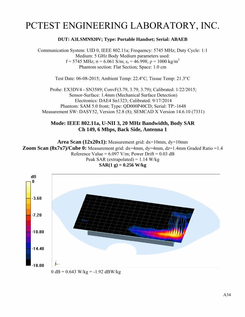
A34
PCTEST ENGINEERING LABORATORY, INC.
DUT: A3LSMN920V; Type: Portable Handset; Serial: ABAEB
Communication System: UID 0, IEEE 802.11a; Frequency: 5745 MHz; Duty Cycle: 1:1 Medium: 5 GHz Body Medium parameters used:
f = 5745 MHz; σ = 6.061 S/m; εr = 46.998; ρ = 1000 kg/m3 Phantom section: Flat Section; Space: 1.0 cm
Test Date: 06-08-2015; Ambient Temp: 22.4°C; Tissue Temp: 21.3°C
Probe: EX3DV4 - SN3589; ConvF(3.79, 3.79, 3.79); Calibrated: 1/22/2015; Sensor-Surface: 1.4mm (Mechanical Surface Detection)
Electronics: DAE4 Sn1323; Calibrated: 9/17/2014 Phantom: SAM 5.0 front; Type: QD000P40CD; Serial: TP:-1648
Measurement SW: DASY52, Version 52.8 (8); SEMCAD X Version 14.6.10 (7331)
Mode: IEEE 802.11a, U-NII 3, 20 MHz Bandwidth, Body SAR Ch 149, 6 Mbps, Back Side, Antenna 1
Area Scan (12x20x1): Measurement grid: dx=10mm, dy=10mm
Zoom Scan (8x7x7)/Cube 0: Measurement grid: dx=4mm, dy=4mm, dz=1.4mm Graded Ratio =1.4 Reference Value = 6.097 V/m; Power Drift = 0.03 dB
Peak SAR (extrapolated) = 1.14 W/kg SAR(1 g) = 0.256 W/kg
0 dB = 0.643 W/kg = -1.92 dBW/kg

A35
PCTEST ENGINEERING LABORATORY, INC.
DUT: A3LSMN920V; Type: Portable Handset; Serial: ADDBE
Communication System: UID 0, GSM GPRS; 3 Tx slots; Frequency: 1909.8 MHz; Duty Cycle: 1:2.76 Medium: 1900 Body Medium parameters used:
f = 1910 MHz; σ = 1.552 S/m; εr = 51.506; ρ = 1000 kg/m3 Phantom section: Flat Section; Space: 0.5 cm
Test Date: 06-18-2015; Ambient Temp: 22.0°C; Tissue Temp: 22.0°C
Probe: ES3DV3 - SN3263; ConvF(4.66, 4.66, 4.66); Calibrated: 5/20/2015; Sensor-Surface: 3mm (Mechanical Surface Detection)
Electronics: DAE4 Sn1408; Calibrated: 10/23/2014 Phantom: SAM with CRP (Left); Type: SAM; Serial: 1715
Measurement SW: DASY52, Version 52.8 (8); SEMCAD X Version 14.6.10 (7331)
Mode: GPRS 1900, Extremity SAR, Bottom Edge, High.ch, 3 Tx Slots
Area Scan (11x8x1): Measurement grid: dx=5mm, dy=15mm Zoom Scan (5x5x7)/Cube 0: Measurement grid: dx=8mm, dy=8mm, dz=5mm
Reference Value = 54.433 V/m; Power Drift = 0.01 dB Peak SAR (extrapolated) = 7.21 W/kg
SAR(10 g) = 2.05 W/kg
0 dB = 5.22 W/kg = 7.18 dBW/kg

A36
PCTEST ENGINEERING LABORATORY, INC.
DUT: A3LSMN920V; Type: Portable Handset; Serial: ADDBE
Communication System: UID 0, UMTS; Frequency: 1907.6 MHz; Duty Cycle: 1:1 Medium: 1900 Body Medium parameters used (interpolated): f = 1907.6 MHz; σ = 1.572 S/m; εr = 52.351; ρ = 1000 kg/m3
Phantom section: Flat Section; Space 0.5 cm
Test Date: 06-13-2015; Ambient Temp: 21.3°C; Tissue Temp: 21.3°C
Probe: ES3DV3 - SN3263; ConvF(4.66, 4.66, 4.66); Calibrated: 5/20/2015; Sensor-Surface: 3mm (Mechanical Surface Detection)
Electronics: DAE4 Sn1408; Calibrated: 10/23/2014 Phantom: SAM with CRP (Left); Type: SAM; Serial: 1715
Measurement SW: DASY52, Version 52.8 (8); SEMCAD X Version 14.6.10 (7331)
Mode UMTS 1900, Extremity SAR, Bottom Edge, High.ch
Area Scan (11x8x1): Measurement grid: dx=5mm, dy=15mm Zoom Scan (5x6x7)/Cube 0: Measurement grid: dx=8mm, dy=8mm, dz=5mm
Reference Value = 50.810 V/m; Power Drift = 0.04 dB Peak SAR (extrapolated) = 8.55 W/kg
SAR(10 g) = 2.37 W/kg
0 dB = 6.15 W/kg = 7.89 dBW/kg

A37
PCTEST ENGINEERING LABORATORY, INC.
DUT: A3LSMN920V; Type: Portable Handset; Serial: AC31E
Communication System: UID 0, CDMA; Frequency: 1880 MHz; Duty Cycle: 1:1 Medium: 1900 Body Medium parameters used:
f = 1880 MHz; σ = 1.524 S/m; εr = 52.155; ρ = 1000 kg/m3 Phantom section: Flat Section; Space: 0.5 cm
Test Date: 06-22-2015; Ambient Temp: 20.7°C; Tissue Temp: 21.7°C
Probe: ES3DV3 - SN3263; ConvF(4.66, 4.66, 4.66); Calibrated: 5/20/2015; Sensor-Surface: 3mm (Mechanical Surface Detection)
Electronics: DAE4 Sn1408; Calibrated: 10/23/2014 Phantom: SAM with CRP (Left); Type: SAM; Serial: 1715
Measurement SW: DASY52, Version 52.8 (8); SEMCAD X Version 14.6.10 (7331)
Mode: PCS EVDO Rev.0, Extremity SAR, Bottom Edge, Mid.ch
Area Scan (13x9x1): Measurement grid: dx=5mm, dy=15mm Zoom Scan (5x5x7)/Cube 0: Measurement grid: dx=8mm, dy=8mm, dz=5mm
Reference Value = 67.959 V/m; Power Drift = 0.01 dB Peak SAR (extrapolated) = 10.8 W/kg
SAR(10 g) = 3.07 W/kg
0 dB = 7.83 W/kg = 8.94 dBW/kg

A38
PCTEST ENGINEERING LABORATORY, INC.
DUT: A3LSMN920V; Type: Portable Handset; Serial: AC258
Communication System: UID 0, LTE Band 4 (AWS); Frequency: 1732.5 MHz; Duty Cycle: 1:1 Medium: 1750 Body Medium parameters used (interpolated): f = 1732.5 MHz; σ = 1.445 S/m; εr = 52.119; ρ = 1000 kg/m3
Phantom section: Flat Section; Space: 0.0 cm
Test Date: 06-12-2015; Ambient Temp: 22.0°C; Tissue Temp: 22.6°C
Probe: ES3DV3 - SN3318; ConvF(4.95, 4.95, 4.95); Calibrated: 1/23/2015; Sensor-Surface: 3mm (Mechanical Surface Detection)
Electronics: DAE4 Sn1272; Calibrated: 1/14/2015 Phantom: ELI v6.0; Type: QDOVA003AA; Serial: TP:2027
Measurement SW: DASY52, Version 52.8 (8); SEMCAD X Version 14.6.10 (7331)
Mode: LTE Band 4 (AWS), Extremity SAR, Bottom Edge, Mid.ch 20 MHz Bandwidth, QPSK, 1 RB, 0 RB Offset
Area Scan (13x9x1): Measurement grid: dx=5mm, dy=15mm
Zoom Scan (5x5x7)/Cube 0: Measurement grid: dx=8mm, dy=8mm, dz=5mm Reference Value = 65.693 V/m; Power Drift = 0.07 dB
Peak SAR (extrapolated) = 13.5 W/kg SAR(10 g) = 2.25 W/kg
0 dB = 7.28 W/kg = 8.62 dBW/kg

A39
PCTEST ENGINEERING LABORATORY, INC.
DUT: A3LSMN920V; Type: Portable Handset; Serial: AB613
Communication System: UID 0, LTE Band 2 (PCS); Frequency: 1880 MHz; Duty Cycle: 1:1 Medium: 1900 Body Medium parameters used:
f = 1880 MHz; σ = 1.54 S/m; εr = 52.457; ρ = 1000 kg/m3 Phantom section: Flat Section; Space: 0.5 cm
Test Date: 06-13-2015; Ambient Temp: 21.3°C; Tissue Temp: 21.3°C
Probe: ES3DV3 - SN3263; ConvF(4.66, 4.66, 4.66); Calibrated: 5/20/2015; Sensor-Surface: 3mm (Mechanical Surface Detection)
Electronics: DAE4 Sn1408; Calibrated: 10/23/2014 Phantom: SAM with CRP (Left); Type: SAM; Serial: 1715
Measurement SW: DASY52, Version 52.8 (8); SEMCAD X Version 14.6.10 (7331)
Mode: LTE Band 2 (PCS), Extremity SAR, Bottom Edge, Mid.ch 20 MHz Bandwidth, QPSK, 1 RB, 0 RB Offset
Area Scan (13x9x1): Measurement grid: dx=5mm, dy=15mm
Zoom Scan (5x5x7)/Cube 0: Measurement grid: dx=8mm, dy=8mm, dz=5mm Reference Value = 62.654 V/m; Power Drift = 0.06 dB
Peak SAR (extrapolated) = 8.82 W/kg SAR(10 g) = 2.54 W/kg
0 dB = 6.42 W/kg = 8.08 dBW/kg
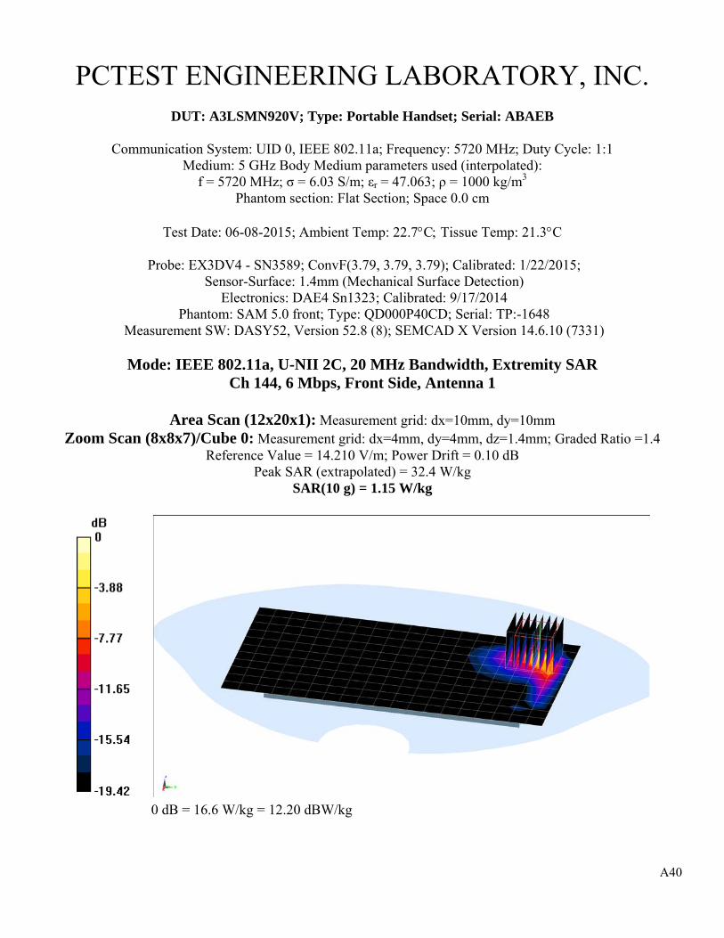
A40
PCTEST ENGINEERING LABORATORY, INC.
DUT: A3LSMN920V; Type: Portable Handset; Serial: ABAEB
Communication System: UID 0, IEEE 802.11a; Frequency: 5720 MHz; Duty Cycle: 1:1 Medium: 5 GHz Body Medium parameters used (interpolated):
f = 5720 MHz; σ = 6.03 S/m; εr = 47.063; ρ = 1000 kg/m3 Phantom section: Flat Section; Space 0.0 cm
Test Date: 06-08-2015; Ambient Temp: 22.7°C; Tissue Temp: 21.3°C
Probe: EX3DV4 - SN3589; ConvF(3.79, 3.79, 3.79); Calibrated: 1/22/2015; Sensor-Surface: 1.4mm (Mechanical Surface Detection)
Electronics: DAE4 Sn1323; Calibrated: 9/17/2014 Phantom: SAM 5.0 front; Type: QD000P40CD; Serial: TP:-1648
Measurement SW: DASY52, Version 52.8 (8); SEMCAD X Version 14.6.10 (7331)
Mode: IEEE 802.11a, U-NII 2C, 20 MHz Bandwidth, Extremity SAR Ch 144, 6 Mbps, Front Side, Antenna 1
Area Scan (12x20x1): Measurement grid: dx=10mm, dy=10mm
Zoom Scan (8x8x7)/Cube 0: Measurement grid: dx=4mm, dy=4mm, dz=1.4mm; Graded Ratio =1.4 Reference Value = 14.210 V/m; Power Drift = 0.10 dB
Peak SAR (extrapolated) = 32.4 W/kg SAR(10 g) = 1.15 W/kg
0 dB = 16.6 W/kg = 12.20 dBW/kg
© 2015 PCTEST Engineering Laboratory, Inc.
A P P E N D I X B : S Y S T E M V E R I F I C A T I O N

B1
PCTEST ENGINEERING LABORATORY, INC.
DUT: Dipole 750 MHz; Type: D750V3; Serial: 1003
Communication System: UID 0, CW; Frequency: 750 MHz; Duty Cycle: 1:1 Medium: 750 Head Medium parameters used (interpolated): f = 750 MHz; σ = 0.893 S/m; εr = 42.028; ρ = 1000 kg/m3
Phantom section: Flat Section; Space: 1.5 cm
Test Date: 06-10-2015; Ambient Temp: 23.4C Tissue Temp: 22.1C
Probe: ES3DV3 - SN3318; ConvF(6.58, 6.58, 6.58); Calibrated: 1/23/2015; Sensor-Surface: 3mm (Mechanical Surface Detection)
Electronics: DAE4 Sn1272; Calibrated: 1/14/2015 Phantom: SAM Front; Type: SAM; Serial: 1686
Measurement SW: DASY52, Version 52.8 (8); SEMCAD X Version 14.6.10 (7331)
750 MHz System Verification
Area Scan (7x15x1): Measurement grid: dx=15mm, dy=15mm Zoom Scan (5x5x7)/Cube 0: Measurement grid: dx=8mm, dy=8mm, dz=5mm
Input Power = 23.0 dBm (200 mW) Peak SAR (extrapolated) = 2.51 W/kg
SAR(1 g) = 1.66 W/kg Deviation(1 g) = 2.60%
0 dB = 1.96 W/kg = 2.92 dBW/kg

B2
PCTEST ENGINEERING LABORATORY, INC.
DUT: Dipole 835 MHz; Type: D835V2; Serial: 4d133
Communication System: UID 0, CW; Frequency: 835 MHz; Duty Cycle: 1:1 Medium: 835 Head Medium parameters used:
f = 835 MHz; σ = 0.898 S/m; εr = 40.464; ρ = 1000 kg/m3 Phantom section: Flat Section; Space: 1.5 cm
Test Date: 06-08-2015; Ambient Temp: 22.3C Tissue Temp: 21.5C
Probe: ES3DV3 - SN3288; ConvF(6.51, 6.51, 6.51); Calibrated: 9/24/2014; Sensor-Surface: 3mm (Mechanical Surface Detection)
Electronics: DAE4 Sn1364; Calibrated: 9/18/2014 Phantom: SAM with CRP v4.0; Type: QD000P40CD; Serial: TP:1797
Measurement SW: DASY52, Version 52.8 (8); SEMCAD X Version 14.6.10 (7331)
835 MHz System Verification
Area Scan (7x14x1): Measurement grid: dx=15mm, dy=15mm Zoom Scan (5x5x7)/Cube 0: Measurement grid: dx=8mm, dy=8mm, dz=5mm
Input Power = 23.0 dBm (200 mW) Peak SAR (extrapolated) = 2.93 W/kg
SAR(1 g) = 1.94 W/kg Deviation(1 g) = 5.43%
0 dB = 2.28 W/kg = 3.58 dBW/kg

B3
PCTEST ENGINEERING LABORATORY, INC.
DUT: Dipole 835 MHz; Type: D835V2; Serial: 4d132
Communication System: UID 0, CW; Frequency: 835 MHz; Duty Cycle: 1:1 Medium: 835 Head Medium parameters used:
f = 835 MHz; σ = 0.894 S/m; εr = 40.228; ρ = 1000 kg/m3 Phantom section: Flat Section; Space: 1.5 cm
Test Date: 06-17-2015; Ambient Temp: 22.7C Tissue Temp: 22.0C
Probe: ES3DV3 - SN3263; ConvF(6.18, 6.18, 6.18); Calibrated: 5/20/2015; Sensor-Surface: 3mm (Mechanical Surface Detection)
Electronics: DAE4 Sn1408; Calibrated: 10/23/2014 Phantom: SAM with CRP v5.0 (Right); Type: QD000P40CD; Serial: TP:1759
Measurement SW: DASY52, Version 52.8 (8); SEMCAD X Version 14.6.10 (7331)
835 MHz System Verification
Area Scan (7x14x1): Measurement grid: dx=15mm, dy=15mm Zoom Scan (5x5x7)/Cube 0: Measurement grid: dx=8mm, dy=8mm, dz=5mm
Input Power = 23.0 dBm (200 mW) Peak SAR (extrapolated) = 2.84 W/kg
SAR(1 g) = 1.89 W/kg Deviation(1 g) = 2.16%
0 dB = 2.22 W/kg = 3.46 dBW/kg

B4
PCTEST ENGINEERING LABORATORY, INC.
DUT: Dipole 1750 MHz; Type: D1750V2; Serial: 1051
Communication System: UID 0, CW; Frequency: 1750 MHz; Duty Cycle: 1:1 Medium: 1750 Head Medium parameters used:
f = 1750 MHz; σ = 1.35 S/m; εr = 39.087; ρ = 1000 kg/m3 Phantom section: Flat Section; Space: 1.0 cm
Test Date: 06-12-2015; Ambient Temp: 22.7C Tissue Temp: 22.9C
Probe: ES3DV3 - SN3288; ConvF(5.38, 5.38, 5.38); Calibrated: 9/24/2014; Sensor-Surface: 3mm (Mechanical Surface Detection)
Electronics: DAE4 Sn1364; Calibrated: 9/18/2014 Phantom: SAM with CRP v4.0; Type: QD000P40CD; Serial: TP:1797
Measurement SW: DASY52, Version 52.8 (8); SEMCAD X Version 14.6.10 (7331)
1750 MHz System Verification
Area Scan (7x9x1): Measurement grid: dx=15mm, dy=15mm Zoom Scan (5x5x7)/Cube 0: Measurement grid: dx=8mm, dy=8mm, dz=5mm
Input Power = 20.0 dBm (100 mW) Peak SAR (extrapolated) = 6.77 W/kg
SAR(1 g) = 3.77 W/kg Deviation(1 g) = 4.14%
0 dB = 4.71 W/kg = 6.73 dBW/kg

B5
PCTEST ENGINEERING LABORATORY, INC.
DUT: Dipole 1900 MHz; Type: D1900V2; Serial: 5d141
Communication System: UID 0, CW; Frequency: 1900 MHz; Duty Cycle: 1:1 Medium: 1900 Head Medium parameters used (interpolated): f = 1900 MHz; σ = 1.418 S/m; εr = 39.591; ρ = 1000 kg/m3
Phantom section: Flat Section; Space: 1.0 cm
Test Date: 06-14-2015; Ambient Temp: 22.5C Tissue Temp: 22.0C
Probe: ES3DV3 - SN3318; ConvF(5.05, 5.05, 5.05); Calibrated: 1/23/2015; Sensor-Surface: 3mm (Mechanical Surface Detection)
Electronics: DAE4 Sn1272; Calibrated: 1/14/2015 Phantom: SAM Front; Type: SAM; Serial: 1686
Measurement SW: DASY52, Version 52.8 (8); SEMCAD X Version 14.6.10 (7331)
1900 MHz System Verification
Area Scan (7x10x1): Measurement grid: dx=15mm, dy=15mm Zoom Scan (5x5x7)/Cube 0: Measurement grid: dx=8mm, dy=8mm, dz=5mm
Input Power = 20.0 dBm (100 mW) Peak SAR (extrapolated) = 7.98 W/kg
SAR(1 g) = 4.31 W/kg Deviation(1 g) = 8.02%
0 dB = 5.53 W/kg = 7.43 dBW/kg

B6
PCTEST ENGINEERING LABORATORY, INC.
DUT: Dipole 2450 MHz; Type: D2450V2; Serial: 719
Communication System: UID 0, CW; Frequency: 2450 MHz; Duty Cycle: 1:1 Medium: 2400 Head Medium parameters used:
f = 2450 MHz; σ = 1.825 S/m; εr = 38.879; ρ = 1000 kg/m3 Phantom section: Flat Section; Space: 1.0 cm
Test Date: 06-17-2015; Ambient Temp: 23.0C Tissue Temp: 22.2C
Probe: ES3DV3 - SN3332; ConvF(4.49, 4.49, 4.49); Calibrated: 9/18/2014; Sensor-Surface: 3mm (Mechanical Surface Detection)
Electronics: DAE4 Sn1323; Calibrated: 9/17/2014 Phantom: SAM V5.0 Right; Type: QD000P40CD; Serial: 1647
Measurement SW: DASY52, Version 52.8 (8); SEMCAD X Version 14.6.10 (7331)
2450 MHz System Verification
Area Scan (8x9x1): Measurement grid: dx=12mm, dy=12mm Zoom Scan (7x7x7)/Cube 0: Measurement grid: dx=5mm, dy=5mm, dz=5mm
Input Power = 20.0 dBm (100 mW) Peak SAR (extrapolated) = 11.0 W/kg
SAR(1 g) = 5.17 W/kg Deviation(1 g) = -0.77%
0 dB = 6.86 W/kg = 8.36 dBW/kg

B7
PCTEST ENGINEERING LABORATORY, INC.
DUT: Dipole 5300 MHz; Type: D5GHzV2; Serial: 1057
Communication System: UID 0, CW; Frequency: 5300 MHz; Duty Cycle: 1:1 Medium: 5 GHz Head Medium parameters used:
f = 5300 MHz; σ = 4.72 S/m; εr = 34.391; ρ = 1000 kg/m3 Phantom section: Flat Section; Space: 1.0 cm
Test Date: 06-15-2015; Ambient Temp: 23.1C Tissue Temp: 21.6C
Probe: EX3DV4 - SN7357; ConvF(4.93, 4.93, 4.93); Calibrated: 4/23/2015; Sensor-Surface: 1.4mm (Mechanical Surface Detection)
Electronics: DAE4 Sn1334; Calibrated: 3/13/2015 Phantom: SAM v5.0 front; Type: QD000P40CD; Serial: TP-1646
Measurement SW: DASY52, Version 52.8 (8); SEMCAD X Version 14.6.10 (7331)
5300 MHz System Verification
Area Scan (7x8x1): Measurement grid: dx=10mm, dy=10mm Zoom Scan (8x8x7)/Cube 0: Measurement grid: dx=4mm, dy=4mm, dz=1.4mm; Graded Ratio =1.4
Input Power = 17.0 dBm (50 mW) Peak SAR (extrapolated) = 18.1 W/kg
SAR(1 g) = 4.44 W/kg Deviation(1 g) = 4.84%
0 dB = 10.6 W/kg = 10.25 dBW/kg

B8
PCTEST ENGINEERING LABORATORY, INC.
DUT: Dipole 5500 MHz; Type: D5GHzV2; Serial: 1057
Communication System: UID 0, CW; Frequency: 5500 MHz; Duty Cycle: 1:1 Medium: 5 GHz Head Medium parameters used:
f = 5500 MHz; σ = 4.95 S/m; εr = 34.051; ρ = 1000 kg/m3 Phantom section: Flat Section; Space: 1.0 cm
Test Date: 06-15-2015; Ambient Temp: 22.5C Tissue Temp: 21.6C
Probe: EX3DV4 - SN7357; ConvF(4.7, 4.7, 4.7); Calibrated: 4/23/2015; Sensor-Surface: 1.4mm (Mechanical Surface Detection)
Electronics: DAE4 Sn1334; Calibrated: 3/13/2015 Phantom: SAM v5.0 front; Type: QD000P40CD; Serial: TP-1646
Measurement SW: DASY52, Version 52.8 (8); SEMCAD X Version 14.6.10 (7331)
5500 MHz System Verification
Area Scan (7x7x1): Measurement grid: dx=10mm, dy=10mm Zoom Scan (8x8x7)/Cube 0: Measurement grid: dx=4mm, dy=4mm, dz=1.4mm; Graded Ratio =1.4
Input Power = 17.0 dBm (50 mW) Peak SAR (extrapolated) = 18.2 W/kg
SAR(1 g) = 4.28 W/kg Deviation(1 g) = 1.54%
0 dB = 10.0 W/kg = 10.00 dBW/kg

B9
PCTEST ENGINEERING LABORATORY, INC.
DUT: Dipole 5800 MHz; Type: D5GHzV2; Serial: 1057
Communication System: UID 0, CW; Frequency: 5800 MHz; Duty Cycle: 1:1 Medium: 5 GHz Head Medium parameters used:
f = 5800 MHz; σ = 5.268 S/m; εr = 33.587; ρ = 1000 kg/m3 Phantom section: Flat Section; Space: 1.0 cm
Test Date: 06-15-2015; Ambient Temp: 22.7C Tissue Temp: 21.6C
Probe: EX3DV4 - SN7357; ConvF(4.41, 4.41, 4.41); Calibrated: 4/23/2015; Sensor-Surface: 1.4mm (Mechanical Surface Detection)
Electronics: DAE4 Sn1334; Calibrated: 3/13/2015 Phantom: SAM v5.0 front; Type: QD000P40CD; Serial: TP-1646
Measurement SW: DASY52, Version 52.8 (8); SEMCAD X Version 14.6.10 (7331)
5800 MHz System Verification
Area Scan (7x7x1): Measurement grid: dx=10mm, dy=10mm Zoom Scan (8x8x7)/Cube 0: Measurement grid: dx=4mm, dy=4mm, dz=1.4mm; Graded Ratio =1.4
Input Power = 17.0 dBm (50 mW) Peak SAR (extrapolated) = 18.5 W/kg
SAR(1 g) = 4.2 W/kg Deviation(1 g) = 3.58%
0 dB = 10.3 W/kg = 10.13 dBW/kg

B10
PCTEST ENGINEERING LABORATORY, INC.
DUT: Dipole 750 MHz; Type: D750V3; Serial: 1003
Communication System: UID 0, CW; Frequency: 750 MHz; Duty Cycle: 1:1 Medium: 750 Body Medium parameters used (interpolated):
f = 750 MHz; σ = 0.964 S/m; εr = 54.885; ρ = 1000 kg/m3 Phantom section: Flat Section; Space: 1.5 cm
Test Date: 06-16-2015; Ambient Temp: 24.8C Tissue Temp: 23.0C
Probe: ES3DV3 - SN3263; ConvF(6.07, 6.07, 6.07); Calibrated: 5/20/2015; Sensor-Surface: 3mm (Mechanical Surface Detection)
Electronics: DAE4 Sn1408; Calibrated: 10/23/2014 Phantom: SAM with CRP v5.0 (Right); Type: QD000P40CD; Serial: TP:1759
Measurement SW: DASY52, Version 52.8 (8); SEMCAD X Version 14.6.10 (7331)
750 MHz System Verification
Area Scan (7x15x1): Measurement grid: dx=15mm, dy=15mm Zoom Scan (5x5x7)/Cube 0: Measurement grid: dx=8mm, dy=8mm, dz=5mm
Input Power = 23.0 dBm (200 mW) Peak SAR (extrapolated) = 2.52 W/kg
SAR(1 g) = 1.74 W/kg Deviation(1 g) = 2.84%
0 dB = 2.02 W/kg = 3.05 dBW/kg

B11
PCTEST ENGINEERING LABORATORY, INC.
DUT: Dipole 835 MHz; Type: D835V2; Serial: 4d133
Communication System: UID 0, CW; Frequency: 835 MHz; Duty Cycle: 1:1 Medium: 835 Body Medium parameters used:
f = 835 MHz; σ = 0.982 S/m; εr = 54.062; ρ = 1000 kg/m3 Phantom section: Flat Section; Space: 1.5 cm
Test Date: 06-10-2015; Ambient Temp: 23.3C Tissue Temp: 21.9C
Probe: ES3DV3 - SN3288; ConvF(6.32, 6.32, 6.32); Calibrated: 9/24/2014; Sensor-Surface: 3mm (Mechanical Surface Detection)
Electronics: DAE4 Sn1364; Calibrated: 9/18/2014 Phantom: ELI v5.0; Type: QDOVA001BB; Serial: 1229
Measurement SW: DASY52, Version 52.8 (8); SEMCAD X Version 14.6.10 (7331)
835 MHz System Verification
Area Scan (7x14x1): Measurement grid: dx=15mm, dy=15mm Zoom Scan (5x5x7)/Cube 0: Measurement grid: dx=8mm, dy=8mm, dz=5mm
Input Power = 23.0 dBm (200 mW) Peak SAR (extrapolated) = 2.99 W/kg
SAR(1 g) = 2.03 W/kg Deviation(1 g) = 8.56%
0 dB = 2.37 W/kg = 3.75 dBW/kg

B12
PCTEST ENGINEERING LABORATORY, INC.
DUT: Dipole 835 MHz; Type: D835V2; Serial: 4d133
Communication System: UID 0, CW; Frequency: 835 MHz; Duty Cycle: 1:1 Medium: 835 Body Medium parameters used:
f = 835 MHz; σ = 1 S/m; εr = 53.915; ρ = 1000 kg/m3 Phantom section: Flat Section; Space: 1.5 cm
Test Date: 06-13-2015; Ambient Temp: 23.2C Tissue Temp: 21.8C
Probe: ES3DV3 - SN3318; ConvF(6.23, 6.23, 6.23); Calibrated: 1/23/2015; Sensor-Surface: 3mm (Mechanical Surface Detection)
Electronics: DAE4 Sn1272; Calibrated: 1/14/2015 Phantom: ELI v6.0; Type: QDOVA003AA; Serial: TP:2027
Measurement SW: DASY52, Version 52.8 (8); SEMCAD X Version 14.6.10 (7331)
835 MHz System Verification
Area Scan (7x14x1): Measurement grid: dx=15mm, dy=15mm Zoom Scan (5x5x7)/Cube 0: Measurement grid: dx=8mm, dy=8mm, dz=5mm
Input Power = 23.0 dBm (200 mW) Peak SAR (extrapolated) = 2.95 W/kg
SAR(1 g) = 1.99 W/kg Deviation(1 g) = 6.42%
0 dB = 2.42 W/kg = 3.84 dBW/kg

B13
PCTEST ENGINEERING LABORATORY, INC.
DUT: Dipole 1750 MHz; Type: D1750V2; Serial: 1051
Communication System: UID 0, CW; Frequency: 1750 MHz; Duty Cycle: 1:1 Medium: 1750 Body Medium parameters used:
f = 1750 MHz; σ = 1.463 S/m; εr = 52.037; ρ = 1000 kg/m3 Phantom section: Flat Section; Space: 1.0 cm
Test Date: 06-12-2015; Ambient Temp: 22.0C Tissue Temp: 22.6C
Probe: ES3DV3 - SN3318; ConvF(4.95, 4.95, 4.95); Calibrated: 1/23/2015; Sensor-Surface: 3mm (Mechanical Surface Detection)
Electronics: DAE4 Sn1272; Calibrated: 1/14/2015 Phantom: ELI v6.0; Type: QDOVA003AA; Serial: TP:2027
Measurement SW: DASY52, Version 52.8 (8); SEMCAD X Version 14.6.10 (7331)
1750 MHz System Verification
Area Scan (7x9x1): Measurement grid: dx=15mm, dy=15mm Zoom Scan (5x5x7)/Cube 0: Measurement grid: dx=8mm, dy=8mm, dz=5mm
Input Power = 20.0 dBm (100 mW) Peak SAR (extrapolated) = 6.59 W/kg
SAR(1 g) = 3.76 W/kg; SAR(10 g) = 2 W/kg Deviation(1 g) = 1.35%; Deviation(10 g) = 0.00%
0 dB = 4.68 W/kg = 6.70 dBW/kg

B14
PCTEST ENGINEERING LABORATORY, INC.
DUT: Dipole 1900 MHz; Type: D1900V2; Serial: 5d149
Communication System: UID 0, CW; Frequency: 1900 MHz; Duty Cycle: 1:1 Medium: 1900 Body Medium parameters used (interpolated):
f = 1900 MHz; σ = 1.559 S/m; εr = 51.641; ρ = 1000 kg/m3 Phantom section: Flat Section; Space: 1.0 cm
Test Date: 06-08-2015; Ambient Temp: 21.0C Tissue Temp: 22.0C
Probe: ES3DV3 - SN3263; ConvF(4.66, 4.66, 4.66); Calibrated: 5/20/2015; Sensor-Surface: 3mm (Mechanical Surface Detection)
Electronics: DAE4 Sn1408; Calibrated: 10/23/2014 Phantom: SAM with CRP (Left); Type: SAM; Serial: 1715
Measurement SW: DASY52, Version 52.8 (8); SEMCAD X Version 14.6.10 (7331)
1900 MHz System Verification
Area Scan (7x9x1): Measurement grid: dx=15mm, dy=15mm Zoom Scan (5x5x7)/Cube 0: Measurement grid: dx=8mm, dy=8mm, dz=5mm
Input Power = 20.0 dBm (100 mW) Peak SAR (extrapolated) = 7.45 W/kg
SAR(1 g) = 4.19 W/kg Deviation(1 g) = 3.71%
0 dB = 5.23 W/kg = 7.19 dBW/kg

B15
PCTEST ENGINEERING LABORATORY, INC.
DUT: Dipole 1900 MHz; Type: D1900V2; Serial: 5d141
Communication System: UID 0, CW; Frequency: 1900 MHz; Duty Cycle: 1:1 Medium: 1900 Body Medium parameters used (interpolated):
f = 1900 MHz; σ = 1.541 S/m; εr = 51.562; ρ = 1000 kg/m3 Phantom section: Flat Section; Space: 1.0 cm
Test Date: 06-18-2015; Ambient Temp: 22.0C Tissue Temp: 22.0C
Probe: ES3DV3 - SN3263; ConvF(4.66, 4.66, 4.66); Calibrated: 5/20/2015; Sensor-Surface: 3mm (Mechanical Surface Detection)
Electronics: DAE4 Sn1408; Calibrated: 10/23/2014 Phantom: SAM with CRP (Left); Type: SAM; Serial: 1715
Measurement SW: DASY52, Version 52.8 (8); SEMCAD X Version 14.6.10 (7331)
1900 MHz System Verification
Area Scan (7x10x1): Measurement grid: dx=15mm, dy=15mm Zoom Scan (5x5x7)/Cube 0: Measurement grid: dx=8mm, dy=8mm, dz=5mm
Input Power = 20.0 dBm (100 mW) Peak SAR (extrapolated) = 7.54 W/kg
SAR(1 g) = 4.3 W/kg; SAR(10 g) = 2.25 W/kg Deviation(1 g) = 7.50%; Deviation(10 g) = 6.13%
0 dB = 5.42 W/kg = 7.34 dBW/kg

B16
PCTEST ENGINEERING LABORATORY, INC.
DUT: Dipole 2450 MHz; Type: D2450V2; Serial: 719
Communication System: UID 0, CW; Frequency: 2450 MHz; Duty Cycle: 1:1 Medium: 2450 Body Medium parameters used:
f = 2450 MHz; σ = 2.032 S/m; εr = 51.385; ρ = 1000 kg/m3 Phantom section: Flat Section; Space: 1.0 cm
Test Date: 06-09-2015; Ambient Temp: 21.5C Tissue Temp: 21.9C
Probe: ES3DV3 - SN3318; ConvF(4.37, 4.37, 4.37); Calibrated: 1/23/2015; Sensor-Surface: 3mm (Mechanical Surface Detection)
Electronics: DAE4 Sn1272; Calibrated: 1/14/2015 Phantom: SAM Front; Type: SAM; Serial: 1686
Measurement SW: DASY52, Version 52.8 (8); SEMCAD X Version 14.6.10 (7331)
2450 MHz System Verification
Area Scan (8x9x1): Measurement grid: dx=12mm, dy=12mm Zoom Scan (7x7x7)/Cube 0: Measurement grid: dx=5mm, dy=5mm, dz=5mm
Input Power = 20.0 dBm (100 mW) Peak SAR (extrapolated) = 11.2 W/kg
SAR(1 g) = 5.37 W/kg Deviation(1 g) = 3.67%
0 dB = 7.09 W/kg = 8.51 dBW/kg

B17
PCTEST ENGINEERING LABORATORY, INC.
DUT: Dipole 5300 MHz; Type: D5GHzV2; Serial: 1057
Communication System: UID 0, CW; Frequency: 5300 MHz; Duty Cycle: 1:1 Medium: 5 GHz Body Medium parameters used:
f = 5300 MHz; σ = 5.456 S/m; εr = 47.753; ρ = 1000 kg/m3 Phantom section: Flat Section; Space: 1.0 cm
Test Date: 06-08-2015; Ambient Temp: 22.6C Tissue Temp: 21.3C
Probe: EX3DV4 - SN3589; ConvF(3.79, 3.79, 3.79); Calibrated: 1/22/2015; Sensor-Surface: 1.4mm (Mechanical Surface Detection)
Electronics: DAE4 Sn1323; Calibrated: 9/17/2014 Phantom: SAM 5.0 front; Type: QD000P40CD; Serial: TP:-1648
Measurement SW: DASY52, Version 52.8 (8); SEMCAD X Version 14.6.10 (7331)
5300 MHz System Verification
Area Scan (7x8x1): Measurement grid: dx=10mm, dy=10mm Zoom Scan (8x8x7)/Cube 0: Measurement grid: dx=4mm, dy=4mm, dz=1.4mm; Graded Ratio =1.4
Input Power = 17.0 dBm (50 mW) Peak SAR (extrapolated) = 16.3 W/kg
SAR(1 g) = 3.89 W/kg; SAR(10 g) = 1.09 W/kg Deviation(1 g) = 4.85%; Deviation(10 g) = 4.31%
0 dB = 9.37 W/kg = 9.72 dBW/kg
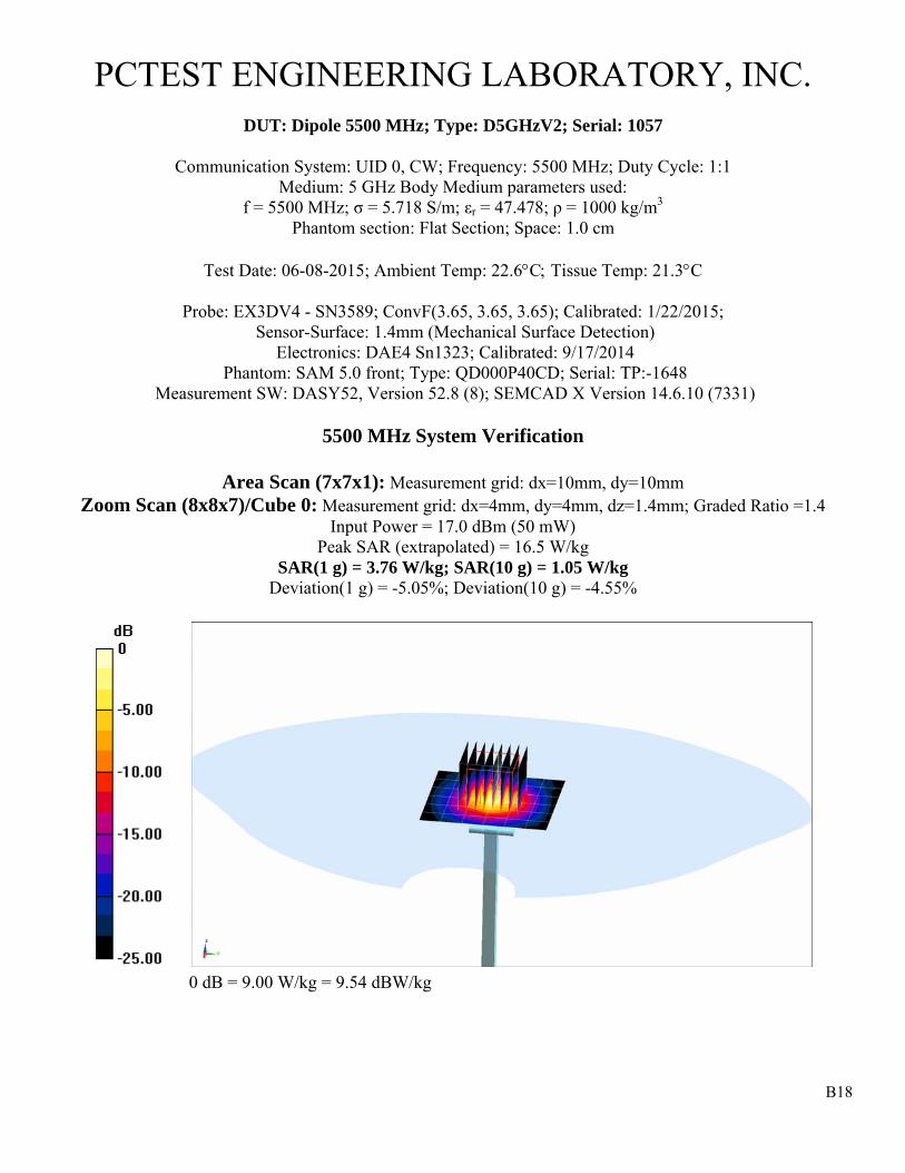
B18
PCTEST ENGINEERING LABORATORY, INC.
DUT: Dipole 5500 MHz; Type: D5GHzV2; Serial: 1057
Communication System: UID 0, CW; Frequency: 5500 MHz; Duty Cycle: 1:1 Medium: 5 GHz Body Medium parameters used:
f = 5500 MHz; σ = 5.718 S/m; εr = 47.478; ρ = 1000 kg/m3 Phantom section: Flat Section; Space: 1.0 cm
Test Date: 06-08-2015; Ambient Temp: 22.6C Tissue Temp: 21.3C
Probe: EX3DV4 - SN3589; ConvF(3.65, 3.65, 3.65); Calibrated: 1/22/2015; Sensor-Surface: 1.4mm (Mechanical Surface Detection)
Electronics: DAE4 Sn1323; Calibrated: 9/17/2014 Phantom: SAM 5.0 front; Type: QD000P40CD; Serial: TP:-1648
Measurement SW: DASY52, Version 52.8 (8); SEMCAD X Version 14.6.10 (7331)
5500 MHz System Verification
Area Scan (7x7x1): Measurement grid: dx=10mm, dy=10mm Zoom Scan (8x8x7)/Cube 0: Measurement grid: dx=4mm, dy=4mm, dz=1.4mm; Graded Ratio =1.4
Input Power = 17.0 dBm (50 mW) Peak SAR (extrapolated) = 16.5 W/kg
SAR(1 g) = 3.76 W/kg; SAR(10 g) = 1.05 W/kg Deviation(1 g) = -5.05%; Deviation(10 g) = -4.55%
0 dB = 9.00 W/kg = 9.54 dBW/kg

B19
PCTEST ENGINEERING LABORATORY, INC.
DUT: Dipole 5800 MHz; Type: D5GHzV2; Serial: 1057
Communication System: UID 0, CW; Frequency: 5800 MHz; Duty Cycle: 1:1 Medium: 5 GHz Body Medium parameters used:
f = 5800 MHz; σ = 6.145 S/m; εr = 46.937; ρ = 1000 kg/m3 Phantom section: Flat Section; Space: 1.0 cm
Test Date: 06-08-2015; Ambient Temp: 22.4C Tissue Temp: 21.3C
Probe: EX3DV4 - SN3589; ConvF(3.79, 3.79, 3.79); Calibrated: 1/22/2015; Sensor-Surface: 1.4mm (Mechanical Surface Detection)
Electronics: DAE4 Sn1323; Calibrated: 9/17/2014 Phantom: SAM 5.0 front; Type: QD000P40CD; Serial: TP:-1648
Measurement SW: DASY52, Version 52.8 (8); SEMCAD X Version 14.6.10 (7331)
5800 MHz System Verification
Area Scan (7x7x1): Measurement grid: dx=10mm, dy=10mm Zoom Scan (8x8x7)/Cube 0: Measurement grid: dx=4mm, dy=4mm, dz=1.4mm; Graded Ratio =1.4
Input Power = 17.0 dBm (50 mW) Peak SAR (extrapolated) = 16.1 W/kg
SAR(1 g) = 3.45 W/kg; SAR (10 g) = 0.966 Deviation(1 g) = -8.12%; Deviation(10 g) = -6.21%
0 dB = 8.51 W/kg = 9.30 dBW/kg