pcm - pleiger control modules
TRANSCRIPT

Pleiger Elektronik GmbH & Co. KG
D-58456 Witten Im Hammertal 51
www.pleiger-elektronik.de
Fon +49 2324 398 333
Fax +49 2324 398 389
PCM - Pleiger Control Modules PCM Series CM4
Manual Version 2020-07
- subject to modification -
• CM4 EHS Control Modul
• CM4-D EHS Control Modul
• CCM Conti Control Modul
• RK16/8 Relay module
• IO8/8/4 IO module
• TII PT 100 module
• DI16 Digital input module
• RO8 Relay output module
• BI Bus interface
• PST Parameter-setup-tool
PCM - Pleiger Control Modules
Directory
Pleiger Elektronik GmbH & Co. KG www.pleiger-elektronik.de Fon +49 2324 398 333
PCM Series CM4 Manual Version 2020-07
Contents
1 General information ..................................................................................................................... 1 1.1 Transportation and storage instructions ............................................................................. 1 1.2 Installation and electrical connection .................................................................................. 1 1.3 Intervention into the component .......................................................................................... 1 1.4 Intended use .......................................................................................................................... 1 1.5 Not intended use ................................................................................................................... 1 1.6 Use in safety related vital functions..................................................................................... 1 1.7 General safety advice ........................................................................................................... 2 1.8 Certificates and Approvals ................................................................................................... 2
2 Overview ...................................................................................................................................... 3 2.1 Modules ................................................................................................................................. 3 2.2 Assembly ............................................................................................................................... 3 2.3 Item numbers of components .............................................................................................. 4
3 Assembly of the system .............................................................................................................. 5 3.1 Requirements of the installation site ................................................................................... 5 3.2 System overview and requirements..................................................................................... 5 3.3 Controlling via mimic diagram ............................................................................................. 6 3.4 Commissioning hints ............................................................................................................ 6 3.5 PCM-system bus ................................................................................................................... 7 3.6 Accessories ........................................................................................................................... 7
3.6.1 Adapting cable ................................................................................................................. 7 3.6.2 Extension cable................................................................................................................ 7 3.6.3 Adapting cable for RK 16/8.............................................................................................. 8 3.6.4 End holder ........................................................................................................................ 8 3.6.5 Noise suppression filter .................................................................................................. 8 3.6.6 CM-ExE capacitor module ............................................................................................... 9 3.6.7 PST-C ................................................................................................................................ 9
4 EHS-control module CM4 .......................................................................................................... 10 4.1 Address setting / operation ................................................................................................ 10
4.1.1 Switches and buttons on the module ........................................................................... 10 4.1.2 Entering commands ...................................................................................................... 10 4.1.3 Activating the special function „Local Stop“ ............................................................... 11
4.2 Control functions for actuators .......................................................................................... 12 4.2.1 Double-acting actuators ................................................................................................ 13 4.2.2 Double-acting actuators with separate hydraulic unit ................................................ 15 4.2.3 Double-acting actuators in Ex type .............................................................................. 15 4.2.4 Single-acting actuators ................................................................................................. 16 4.2.5 Single-acting actuators with separate hydraulic unit .................................................. 18 4.2.6 Single-acting actuator with extended operation by handwheel.................................. 18 4.2.7 Single-acting actuators with extended operation by hand pump ............................... 18 4.2.8 Single-acting actuator in Ex type .................................................................................. 19 4.2.9 MOV, Motor valve ........................................................................................................... 23
4.3 Teach-in ............................................................................................................................... 23 4.4 Indicators ............................................................................................................................. 23
4.4.1 Status LED ...................................................................................................................... 23 4.4.2 Start reports and self-test ............................................................................................. 24
4.5 Wire break and short circuit detection .............................................................................. 25 4.5.1 Mimic Inputs ................................................................................................................... 25 4.5.2 Position feedback inputs ............................................................................................... 26

PCM - Pleiger Control Modules
Directory
Pleiger Elektronik GmbH & Co. KG www.pleiger-elektronik.de Fon +49 2324 398 333
PCM Series CM4 Manual Version 2020-07
4.5.3 Display of wire break and short circuit errors of the mimic inputs ............................ 27 4.6 Lamp test ............................................................................................................................. 28 4.7 Alarm output ........................................................................................................................ 28 4.8 Terminal assignment .......................................................................................................... 29
4.8.1 Connecting Ex-Type actuators ..................................................................................... 30 4.8.2 Connecting spring close actuators with separate hydraulic power pack .................. 30
4.9 Technical data ..................................................................................................................... 31
5 EHS control module CM4-D ...................................................................................................... 32 5.1 Adress setting / operation .................................................................................................. 32 5.2 Extended operating modes ................................................................................................ 32 5.3 Adjusting the operating time .............................................................................................. 32
5.3.1 Calibration of the operating time .................................................................................. 33 5.4 Control functions ................................................................................................................ 33 5.5 Terminal assignment .......................................................................................................... 33 5.6 Technical data ..................................................................................................................... 33
6 Conti Control Module CCM ....................................................................................................... 34 6.1 Address setting / operation ................................................................................................ 34 6.2 Entering commands ............................................................................................................ 34 6.3 Output of analog position signal (actual position) ........................................................... 35
6.3.1 Position measurement ................................................................................................... 35 6.4 Behavior in the event of a power failure ............................................................................ 35 6.5 Display ................................................................................................................................. 35
6.5.1 Position indicator ........................................................................................................... 35 6.5.2 Start messages and self-test ......................................................................................... 35 6.5.3 Status LED ...................................................................................................................... 35
6.6 Extended operation modes ................................................................................................ 36 6.7 Calibration ........................................................................................................................... 37 6.8 Lamp test ............................................................................................................................. 37 6.9 Alarm output ........................................................................................................................ 37 6.10 Terminal assignment .......................................................................................................... 38 6.11 Interface to flowmeter ......................................................................................................... 39 6.12 Technical data ..................................................................................................................... 39
7 Relay module RK16/8 ................................................................................................................ 40 7.1 Address setting / operation ................................................................................................ 40 7.2 Counter function ................................................................................................................. 40 7.3 Operation mode: Digital inputs with off-delay .................................................................. 40 7.4 Indication ............................................................................................................................. 40 7.5 Jumper B1 ........................................................................................................................... 41 7.6 Terminal assignment .......................................................................................................... 41 7.7 Technical Data ..................................................................................................................... 42
8 Input/output module IO8/8/4..................................................................................................... 43 8.1 Address setting / operation ................................................................................................ 43 8.2 Displays ............................................................................................................................... 43
8.2.1 Start messages and self-test ......................................................................................... 44 8.2.2 Lamp test ........................................................................................................................ 44
8.3 Terminal assignment .......................................................................................................... 45 8.4 Technical Data ..................................................................................................................... 46
9 Input-/Output module TII .......................................................................................................... 47 9.1 Address setting / operation ................................................................................................ 47 9.2 Displays ............................................................................................................................... 47
9.2.1 Self-test and start-up indications.................................................................................. 48

PCM - Pleiger Control Modules
Directory
Pleiger Elektronik GmbH & Co. KG www.pleiger-elektronik.de Fon +49 2324 398 333
PCM Series CM4 Manual Version 2020-07
9.2.2 Lamp test ........................................................................................................................ 49 9.3 Terminal assignment ......................................................................................................... 49 9.4 Technical Data ..................................................................................................................... 50
10 Digital input module DI16 .......................................................................................................... 51 10.1 Address setting / operation ................................................................................................ 51 10.2 Counter function ................................................................................................................. 51 10.3 Displays ............................................................................................................................... 51
10.3.1 Lamp test ........................................................................................................................ 51 10.4 Terminal assignment .......................................................................................................... 52 10.5 Technical Data ..................................................................................................................... 53
11 Relay output module RO8 ......................................................................................................... 54 11.1 Address setting / operation ................................................................................................ 54 11.2 Displays ............................................................................................................................... 54
11.2.1 Lamp test ........................................................................................................................ 54 11.3 Terminal assignment .......................................................................................................... 55 11.4 Technical Data ..................................................................................................................... 56
12 Fieldbus interface BI from V2.7 ............................................................................................... 57 12.1 Operation ............................................................................................................................. 57
12.1.1 Parameterisation of the fieldbus ................................................................................... 57 12.1.2 Setting the address of CM (CM3, CM4, CM4-D, CCM) modules .................................. 58 12.1.3 Setting the address and operation mode of the RK16/8 ............................................. 59 12.1.4 Setting the address of the DI16 ..................................................................................... 60 12.1.5 Setting the address and operation mode of the RO8 .................................................. 60 12.1.6 Skipping addresses ....................................................................................................... 61 12.1.7 Parameter matching BI / CM4 ........................................................................................ 61 12.1.8 Display functions ........................................................................................................... 62 12.1.9 Start messages and self-test ......................................................................................... 63 12.1.10 Lamp test ....................................................................................................................... 63 12.1.11 Alarm output ................................................................................................................. 63 12.1.12 Power management ...................................................................................................... 64 12.1.13 Setup of Quick Close functions ................................................................................... 65 12.1.14 Bus termination ............................................................................................................ 66
12.2 Terminal assignment .......................................................................................................... 66 12.3 Technical Data ..................................................................................................................... 67
13 BI Modbus interface (slave) / Data model ................................................................................ 68 13.1 Status register (read only) .................................................................................................. 68
13.1.1 Fieldbus interface BI - status, register 1 ...................................................................... 68 13.1.2 CM3/4 status register ..................................................................................................... 69 13.1.3 CCM status register ....................................................................................................... 70 13.1.4 IO 8/8/4 status register ................................................................................................... 71 13.1.5 TII status and input registers ........................................................................................ 72 13.1.6 RK16/8 status register ................................................................................................... 73 13.1.7 DI16 status register ........................................................................................................ 73 13.1.8 RO8 status register ........................................................................................................ 74
13.2 Control register (read / write) ............................................................................................. 74 13.2.1 Fieldbus interface BI remote control, register 142 ...................................................... 74 13.2.2 CM3/4 control register ................................................................................................... 75 13.2.3 CCM control register ..................................................................................................... 76 13.2.4 IO8/8/4 control register .................................................................................................. 76 13.2.5 TII control register ......................................................................................................... 77 13.2.6 RK16/8 control register .................................................................................................. 78

PCM - Pleiger Control Modules
Directory
Pleiger Elektronik GmbH & Co. KG www.pleiger-elektronik.de Fon +49 2324 398 333
PCM Series CM4 Manual Version 2020-07
13.2.7 DI16 control register ...................................................................................................... 78 13.2.8 RO8 control register ...................................................................................................... 78
13.3 Response monitoring ......................................................................................................... 78 13.4 Extended modbus interface ............................................................................................... 79
13.4.1 Version registers ............................................................................................................ 79 13.4.2 Parameter registers ....................................................................................................... 79
13.5 Register overwiew ............................................................................................................... 80
14 BI Profibus DP interface (slave) ................................................................................................ 81 14.1 Profibus Data model ........................................................................................................... 81
14.1.1 Fieldbus interface to superimposed control system (status words) .......................... 81 14.1.2 Superimposed control system to fieldbus interface (control words) ......................... 82 14.1.3 Data valid bit .................................................................................................................. 82
15 Secondary BI module, passive mode ....................................................................................... 83 15.1 Parameterization of the secondary BI module .................................................................. 84 15.2 Fieldbus interface BI status, register 1 (read only) ........................................................... 84 15.3 Fieldbus interface BI remote control, register 142 (read/write) ........................................ 84 15.4 Operating redundant BI ...................................................................................................... 84 15.5 Alarm output ........................................................................................................................ 84
16 Parameter-Setup-Tool (PST) ..................................................................................................... 85 16.1 PST becomes active bus master on the local bus ............................................................ 85 16.2 PST main menu ................................................................................................................... 86 16.3 „Address Set-Up“ menu ..................................................................................................... 86 16.4 „Parameter setup“ Menu .................................................................................................... 87
16.4.1 Selecting the next or previous CM4 .............................................................................. 87 16.4.2 Selecting a parameter .................................................................................................... 88 16.4.3 Changing the parameter ................................................................................................ 88 16.4.4 Actuator type .................................................................................................................. 88 16.4.5 Timing parameter ........................................................................................................... 88
16.5 Teach-in ............................................................................................................................... 88 16.6 Configuration ....................................................................................................................... 89
16.6.1 Copy and paste .............................................................................................................. 90
17 PCM modules, available versions ............................................................................................ 91 17.1 CM3 ...................................................................................................................................... 91 17.2 CM4 ...................................................................................................................................... 91 17.3 BI .......................................................................................................................................... 91 17.4 IO8/8/4 .................................................................................................................................. 91 17.5 TII .......................................................................................................................................... 91 17.6 RK16/8 .................................................................................................................................. 91 17.7 CCM ...................................................................................................................................... 92 17.8 DI16 ...................................................................................................................................... 92 17.9 RO8 ...................................................................................................................................... 92
18 List of tables .............................................................................................................................. 93
19 List of figures ............................................................................................................................. 96
20 List of abbreviations .................................................................................................................. 98

PCM - Pleiger Control Modules → Content
1. General information
Pleiger Elektronik GmbH & Co. KG www.pleiger-elektronik.de Fon +49 2324 398 333
1 / 99
PCM Series CM4 Manual Version 2020-07
1 General information To use the digital version of this manual with full functionality, please activate the jump function of your
PDF reader. If you are using Adobe Reader, you can activate page navigation via the toolbar settings.
Alternatively, use the key combinations "alt" + left arrow or "alt" + right arrow.
This manual contains instructions and drawings for correct handling and using the equipment. Please
observe all instructions of this manual carefully. Please note that not respecting the information, using
the equipment not according the regulations below, wrong installation or incorrect handling could influ-
ence personal or plant safety seriously! This manual is part of this operation resource. Keep the manual
safe for later use. The manufacturer reserves the right to change performance data, specification data
or the design layout without an advance notice.
1.1 Transportation and storage instructions
The equipment must be inspected upon reception for damages that may have occurred dur-
ing transportation or handling. If damages are obviously, inform the carrier and the manu-
facturer immediately. Dropped components must not be applied because invisible damages
may influence the reliability.
1.2 Installation and electrical connection
The equipment has to be installed by qualified personnel only that are familiar with the safety
requirements and potential risk. Please note the special safety requirements belonging to
the point of installation, generally accepted rules of technology, the connection instruction in
this manual and the available imprint on the component.
1.3 Intervention into the component
If malfunctions occur or something is dubious please contact the manufacturer. Intervention into the
component could heavily affect the safety of person and plant and will lead to termination of liability and
caveat emptor.
1.4 Intended use
To use the equipment is approved only if the instructions of this manual are complied and the use is
appropriate to the type label and to an application it is intended to. In the field the technical specifications
and denoted limit values have to be generally maintained. This applies particular with regard to voltage,
temperature and other noted environmental conditions. The use beyond the specified and approved
edge conditions could put life at risk, damage the component or cause secondary damages to the plant.
1.5 Not intended use
Every use of the component that is not equal to the use described in chapter „1.4 intended use“ is
obtained as not intended use. Damages that result from not intended use and / or result from unauthor-
ised intervention on the component, not according to this manual, or not using original spare parts the
claim for warranty and liability of the manufacturer expires.
1.6 Use in safety related vital functions
It is the responsibility of the user to perform a risk analysis of the whole installation and to define potential safety related functions. It is the responsibility of the user to take care of appropriate measures to achieve the safeness in safety related vital functions.

PCM - Pleiger Control Modules → Content
1. General information
Pleiger Elektronik GmbH & Co. KG www.pleiger-elektronik.de Fon +49 2324 398 333
2 / 99
PCM Series CM4 Manual Version 2020-07
1.7 General safety advice
The safety advices in this manual serve to avert dangers. They are placed prior to the description of a
potentially hazardous situation / work / practice. They are marked with a signal word and a pictogram.
They describe the kind and origin of the hazard and give instructions to avoid injury or damage to the
device or plant.
Signal words for safety advices:
Signal word Severity of hazard
DANGER Signal word for an imminent danger with high risk, resulting in severe injuries or
death if not avoided.
WARNING Signal word for a hazardous situation with medium risk, possibly resulting in se-
vere injuries or death if not avoided.
CAUTION Signal word for a hazardous situation with low risk, resulting in damaged to the
device or the property or minor or medium injuries if not avoided.
NOTICE Signal word for important information to the product.
Pictograms:
Warns of a general
hazard
Warns of an electrical
shock
Notice
1.8 Certificates and Approvals
PCM - Pleiger Control Modules-modules meet the requirements of the following directives:
• 2014/90/EU on marine equipment
• DNVGL Class Guideline CG-0339:2016
Folgende Zertifikate liegen vor:
• Type approval DNVGL: TAA00002SX
CE conformity:
The PCM - Pleiger Control Modules comply with the guidelines of the European Commission on
equipment safety.
Certificates and approvals can be downloaded from our website or ordered from the manufacturer.
Technical Support:
+49 2324 398 333
PCM - Pleiger Control Modules → Content
2. Overview
Pleiger Elektronik GmbH & Co. KG www.pleiger-elektronik.de Fon +49 2324 398 333
3 / 99
PCM Series CM4 Manual Version 2020-07
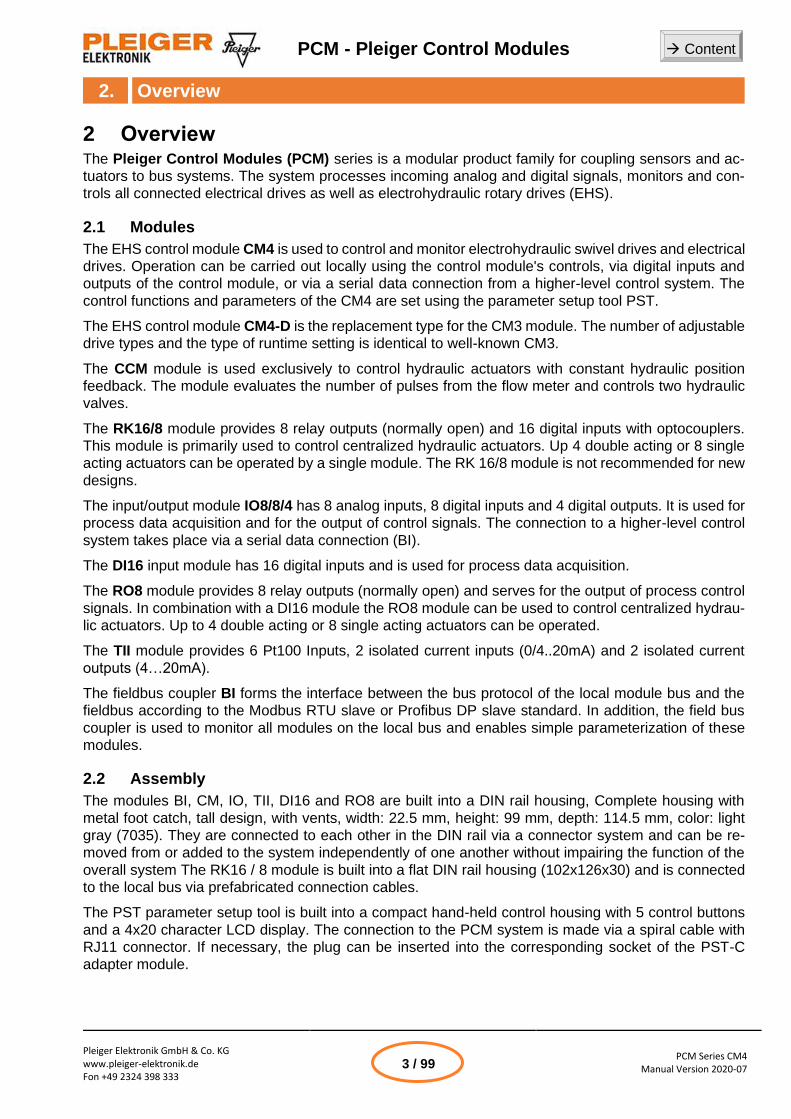
2 Overview The Pleiger Control Modules (PCM) series is a modular product family for coupling sensors and ac-
tuators to bus systems. The system processes incoming analog and digital signals, monitors and con-
trols all connected electrical drives as well as electrohydraulic rotary drives (EHS).
2.1 Modules
The EHS control module CM4 is used to control and monitor electrohydraulic swivel drives and electrical
drives. Operation can be carried out locally using the control module's controls, via digital inputs and
outputs of the control module, or via a serial data connection from a higher-level control system. The
control functions and parameters of the CM4 are set using the parameter setup tool PST.
The EHS control module CM4-D is the replacement type for the CM3 module. The number of adjustable
drive types and the type of runtime setting is identical to well-known CM3.
The CCM module is used exclusively to control hydraulic actuators with constant hydraulic position
feedback. The module evaluates the number of pulses from the flow meter and controls two hydraulic
valves.
The RK16/8 module provides 8 relay outputs (normally open) and 16 digital inputs with optocouplers.
This module is primarily used to control centralized hydraulic actuators. Up 4 double acting or 8 single
acting actuators can be operated by a single module. The RK 16/8 module is not recommended for new
designs.
The input/output module IO8/8/4 has 8 analog inputs, 8 digital inputs and 4 digital outputs. It is used for
process data acquisition and for the output of control signals. The connection to a higher-level control
system takes place via a serial data connection (BI).
The DI16 input module has 16 digital inputs and is used for process data acquisition.
The RO8 module provides 8 relay outputs (normally open) and serves for the output of process control
signals. In combination with a DI16 module the RO8 module can be used to control centralized hydrau-
lic actuators. Up to 4 double acting or 8 single acting actuators can be operated.
The TII module provides 6 Pt100 Inputs, 2 isolated current inputs (0/4..20mA) and 2 isolated current
outputs (4…20mA).
The fieldbus coupler BI forms the interface between the bus protocol of the local module bus and the
fieldbus according to the Modbus RTU slave or Profibus DP slave standard. In addition, the field bus
coupler is used to monitor all modules on the local bus and enables simple parameterization of these
modules.
2.2 Assembly
The modules BI, CM, IO, TII, DI16 and RO8 are built into a DIN rail housing, Complete housing with
metal foot catch, tall design, with vents, width: 22.5 mm, height: 99 mm, depth: 114.5 mm, color: light
gray (7035). They are connected to each other in the DIN rail via a connector system and can be re-
moved from or added to the system independently of one another without impairing the function of the
overall system The RK16 / 8 module is built into a flat DIN rail housing (102x126x30) and is connected
to the local bus via prefabricated connection cables.
The PST parameter setup tool is built into a compact hand-held control housing with 5 control buttons
and a 4x20 character LCD display. The connection to the PCM system is made via a spiral cable with
RJ11 connector. If necessary, the plug can be inserted into the corresponding socket of the PST-C
adapter module.

PCM - Pleiger Control Modules → Content
2. Overview
Pleiger Elektronik GmbH & Co. KG www.pleiger-elektronik.de Fon +49 2324 398 333
4 / 99
PCM Series CM4 Manual Version 2020-07
Fig.2.1: Overview-Image
The local bus connects all modules with a 24V supply voltage, a serial data bus and a common digital
control line for the lamp test. When supplying via the bus of the standard DIN rail, the supply must take
place on the side of the IO and TII modules or on the BI. CM and RK modules can be installed at a
greater distance or on the opposite side.
2.3 Item numbers of components
• EHS control module CM4 934 1100 800
• EHS control module CM4-D 934 1100 850
• EHS control module CM3* 934 1100 100, 110, 120, 130, 140, 150, 160, 170,
180, 190
• Conti control module CCM 934 1100 500
• Relay module RK16/8 934 1100 400
• In-/Out- module IO8/8/4 934 1100 300
• Digital Input module DI16 934 1101 100
• Output module RO8 934 1101 200
• PT 100 module TII 934 1100 600
• Fieldbus coupler BI 934 1100 200 or 934 1100 250
• Parameter setup tool PST 934 1100 900
• PST Connector PST-C 934 1100 950
Note: In the following, a control module CM3, CM4 or CCM is referred to as CM. * Note: The control module CM3 is not recommended for new designs. The description is in a
separate manual.
PCM - Pleiger Control Modules → Content
3. Assembly of the system
Pleiger Elektronik GmbH & Co. KG www.pleiger-elektronik.de Fon +49 2324 398 333
5 / 99
PCM Series CM4 Manual Version 2020-07
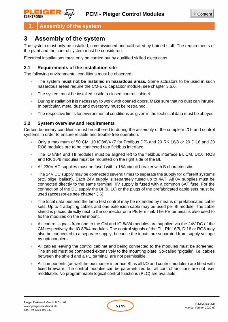
3 Assembly of the system The system must only be installed, commissioned and calibrated by trained staff. The requirements of
the plant and the control system must be considered.
Electrical installations must only be carried out by qualified skilled electricans.
3.1 Requirements of the installation site
The following environmental conditions must be observed:
• The system must not be installed in hazardous areas. Some actuators to be used in such
hazardous areas require the CM-ExE capacitor module, see chapter 3.6.6.
• The system must be installed inside a closed control cabinet.
• During installation it is necessary to work with opened doors. Make sure that no dust can intrude.
In particular, metal dust and overspray must be restrained.
• The respective limits for environmental conditions as given in the technical data must be obeyed.
3.2 System overview and requirements
Certain boundary conditions must be adhered to during the assembly of the complete I/O- and control
systems in order to ensure reliable and trouble free operation.
• Only a maximum of 50 CM, 10 IO8/8/4 (7 for Profibus DP) and 20 RK 16/8 or 20 DI16 and 20
RO8 modules are to be connected to a fieldbus interface.
• The IO 8/8/4 and TII modules must be aligned left to the fieldbus interface BI. CM, DI16, RO8
and RK 16/8 modules must be mounted on the right side of the BI.
• All 230V AC supplies must be fused with a 16A circuit breaker with B characteristic.
• The 24V DC supply may be connected several times to separate the supply for different systems
(etc. bilge, ballast). Each 24V supply is separately fused up to 4AT. All 0V supplies must be
connected directly to the same terminal. 0V supply is fused with a common 6AT fuse. For the
connection of the DC supply the BI (9, 10) or the plugs of the prefabricated cable sets must be
used (accessories see chapter 3.6).
• The local data bus and the lamp test control may be extended by means of prefabricated cable
sets. Up to 4 adapting cables and one extension cable may be used per BI module. The cable
shield is placed directly next to the connector on a PE terminal. The PE terminal is also used to
fix the modules on the rail mount.
• All control signals from and to the CM and IO 8/8/4 modules are supplied via the 24V DC of the
CM respectively the IO 8/8/4 modules. The control signals of the TII, RK 16/8, DI16 or RO8 may
also be connected to a separate supply, because the inputs are separated from supply voltage
by optocouplers.
• All cables leaving the control cabinet and being connected to the modules must be screened.
The shield must be connected extensively to the mounting plate. So-called “pigtails“, i.e. cables
between the shield and a PE terminal, are not permissible.
• All components (as well the busmaster interface BI as all I/O and control modules) are fitted with
fixed firmware. The control modules can be parametrized but all control functions are not user
modifiable. No programmable logical control functions (PLC) are available.

PCM - Pleiger Control Modules → Content
3. Assembly of the system
Pleiger Elektronik GmbH & Co. KG www.pleiger-elektronik.de Fon +49 2324 398 333
6 / 99
PCM Series CM4 Manual Version 2020-07
3.3 Controlling via mimic diagram
The CM modules can be used without a fieldbus interface for applications in which the actuators are controlled exclusively by a mimic diagram. The feeding-in of the 24V DC supply voltage is then via the local bus connector pins 4 and 5 (accessories see chapter 3.6). The voltage must have external fuse protection amounting to a maximum of 6A on the 0V line and 4A on the 24V line. Insofar as neces-sary, a 24V DC lamp test signal is also connected via the local bus connector. The current consump-tion of this control input amounts to approx. 1mA per module.
3.4 Commissioning hints
DANGER Electrical shock
Mains supply with 230 VAC
• All installations must only be carried out by an electrically qualified person.
• Disconnect the system from the mains and secure it against being switched on
unintentionally.
• Obey the accident prevention regulations when testing the live system.
CAUTION Material damage
Incorrectly connected drives or defective cables may cause damage of the CM mod-
ules or the OC feedback modules.
• To avoid this some tests must be performed before 24 VDC or 230 VAC supply
is turned on.
• Follow for this purpose the instructions below.
1. 24V DC and 230V AC are completely separated
from each other and from protective earth (PE), e.g.
the hat rail.Therefore a high insulation resistance
must be measured between those circuits. The in-
sulation resistance measurement should be per-
formed with an insulation resistance meter with 50
to 500V DC test voltage. The following minimum re-
sistance values must be achieved:
Using a standard multi-meter as a substitute may result in uncertain results. This measuring
must be performed during commissioning and should be repeated after any repair works on the
cabling of the actuators.
2. Please also check that pin 13 of the CM3, CM4 module, this is the position feedback input
4...20mA, is connected only for those actuators that really use an analog position feedback sig-
nal.
3. Turn on 230V AC for a few devices only and check proper operation carefully before connecting
the next devices to 230V AC.
1. 0V DC to PE 1 MOhm
2. 0V DC to L, N 1 MOhm
3. 24V DC to PE 1 MOhm
4. 24V DC to L, N 1 MOhm
5. N to PE 1 MOhm
6. L to PE 1 MOhm

PCM - Pleiger Control Modules → Content
3. Assembly of the system
Pleiger Elektronik GmbH & Co. KG www.pleiger-elektronik.de Fon +49 2324 398 333
7 / 99
PCM Series CM4 Manual Version 2020-07
3.5 PCM-system bus
The modules CM4, CM4-D, CCM, IO8 / 8/4, TII, DI16, RO8, BI are connected via the local bus (24V
supply voltage, serial data bus, digital control line for the lamp test) according to the following terminal
assignment of the Bus connector. For connection of the RK16 / 8 relay card to the local bus, see chap-
ter 7.6.
CAUTION Damage to the device / malfunction of the actuators
PRINCIPALLY ONLY apply the 230 VAC supply voltages to the terminals that are
provided. Otherwise the modules may be damaged or destroyed.
Busstecker:
1 Data A EA local data bus according to RS485
2 Data B EA local data bus according to RS485
3 Lamp test E Lamp test input, 24V = lamps on
4 0 VDC E DC supply
5 +24 VDC E DC supply
Tab. 3.1: Bus connector assignment
3.6 Accessories
For the proper installation of PCM systems the following accessories are required.
3.6.1 Adapting cable
This cable is used if the 24V DC supply shall be feed several times. The length of the cable is app.
20cm must not be extended or replaced by a different cable. The modules are fixed on both sides of the
cable by means of an end holder that is fastened on the hat rail. The right plug (4+5) must be connected
to 24V DC power supply. Connect pin 4 to the common 0V directly, connect pin 5 to 24V fused up to
4A.
Fig. 3.2: Adapting cable
Article-No.: 9319710190
3.6.2 Extension cable
This cable is used to connect additional modules on a second hat-rail to the same BI module. Only one
cable can be used per BI module. The shield of the extension cable must be connected to the hat-rail
via PE terminals. These terminals are also used to fix the modules mechanically. The cable is approx.
150 cm long and must not be extended! If such a cable is used the 24V DC power supply must be
connected separately to the modules.
Fig. 3.1: Bus connector

PCM - Pleiger Control Modules → Content
3. Assembly of the system
Pleiger Elektronik GmbH & Co. KG www.pleiger-elektronik.de Fon +49 2324 398 333
8 / 99
PCM Series CM4 Manual Version 2020-07
Fig. 3.3: Extension cable
Article-No.: 9319710180
3.6.3 Adapting cable for RK 16/8
This cable is required to connect one or more relay cards to the local bus of the BI, CM, IO8/8/4, TII,
DI16 or RO8 modules.
Fig. 3.4: Adapting cable for RK16/8
Article-No.: 9319710330
3.6.4 End holder
The end holders are fixed to the hat-rail on the right side of the mod-
ules. If the adapter cable is used one holder is also fixed on the left
side of the modules.
Article-No.: 4639020830
3.6.5 Noise suppression filter
If a BI module is used on the bridge one filter must be inserted in
the common 24V DC supply of all modules (according GL-Rule
EMC1: Using on the bridge or on the open deck).
The current must not exceed 16A. The filter is screwed on the
mounting plate directly. A sufficient electrical and thermal contact
to the mounting plate must be ensured.
Article-No: 4470200050
Fig. 3.5: End holder
Fig. 3.6: Noise suppression filter

PCM - Pleiger Control Modules → Content
3. Assembly of the system
Pleiger Elektronik GmbH & Co. KG www.pleiger-elektronik.de Fon +49 2324 398 333
9 / 99
PCM Series CM4 Manual Version 2020-07
3.6.6 CM-ExE capacitor module
To connect double acting actuators for explosion proof areas to a
CM3 or CM4 module a capacitor module is required.
Article-No: 9311222810
:
3.6.7 PST-C
Connector module for the Parameter Setup Tool PST. On the front
side the PST-C provides a RJ11 socket for the easy connection of
a PST.
The PST shall be plugged onto the local bus at one of both ends.
It is recommended to equip each PCM system with a PST-C that
remains in the system permanently.
Article-No.:9341100950
Fig. 3.7: CM-ExE capacitor module
Fig. 3.8: PST-C

PCM - Pleiger Control Modules → Content
4. EHS-control module CM4
Pleiger Elektronik GmbH & Co. KG www.pleiger-elektronik.de Fon +49 2324 398 333
10 / 99
PCM Series CM4 Manual Version 2020-07
4 EHS-control module CM4 The EHS CM4 control modules monitor and control electro-hydraulic flap or valve actuators manufac-
tured by Pleiger Maschinenbau. One control module is required for each actuator. The actuator can be
connected directly to the control module. The module is equipped with the necessary power relays and
actuator supply voltage fusing.
The EHS control module CM4 is the successor of the CM3 control module. The major im-
provements are:
• All control functions and variants that have been implemented in special versions of
the CM3 are now integrated in the CM4.
• The electrical pump drive and the solenoid valve are now switched off from mains
completely.
• The plug X4 is completely touch protected (IP20). The concerning warning plate is
not required any longer.
• The inputs for limit switches and mimic command input can be parameterized in such
a way that wire break and short circuit can be detected.
• The quad DIP switches that have been used for the setup of the drive type as well
as the runtime potentiometer have been omitted. The necessary setup is now done
by means of separate setup tool the PCM-PST.
4.1 Address setting / operation
4.1.1 Switches and buttons on the module
The EHS control module has several operating and display elements that enable manual on-site oper-
ation of the actuator.
Control element Funktion
switch „local – remote“
In position “local” the drive can be operated by means of the „close-0-
open“ switch. In position „remote” the can be operated using the digital
control inputs or the local serial bus..
button „close – 0 – open“
This button is used to operate the drive while the operating mode is
„local“. If the operation mode is “remote” pressing this button will indi-
cate the device and software version on the BI display.
Tab. 4.1: CM4 controls
Furthermore, operation of the local-remote switch causes the temporary display of the module address
on the fieldbus interface. In addition, these control elements are also used for the address setting of the
CM4 (see 12.1.2).
4.1.2 Entering commands
Travel commands can be issued in three ways:
• Via the "open / close" buttons when the "local" operating mode is set
• Via the control inputs CMD-open / CMD-closed if the operating mode "remote" is set
• Via a move command from the BI module if the "remote" operating mode is set
Fig. 4.1: CM4

PCM - Pleiger Control Modules → Content
4. EHS-control module CM4
Pleiger Elektronik GmbH & Co. KG www.pleiger-elektronik.de Fon +49 2324 398 333
11 / 99
PCM Series CM4 Manual Version 2020-07
NOTE Control inputs
As long as the control inputs are set to CMD-open / CMD-close are set (24V) they
have priority over any control commands that are issued via the BI module.
4.1.3 Activating the special function „Local Stop“
For commissioning or other special cases in which a double-acting actuator is equipped with a hand
pump (no override actuator), the module can be set to "Stop" in local mode. It is then possible to leave
an end position without "follow-up pressing". Double acting continuous drives can also leave the position
as desired. In this state, the "renewed" reaching of an end position leads to the drive being pressed into
this end position.
The "local stop command" is achieved by pressing the command button in remote direction "Open" for
at least 3s before changing to local mode (with the command button still pressed). After changing the
operating mode, the yellow LED flashes briefly several times for 5s to indicate this special function.
Every new command in local mode or a switch back to remote mode cancels the "stop function"!
The special function "Local Stop" is available from CM4 firmware version 4.5.
WARNING Danger from unexpected reaction
If the CM4 receives a valid end position message by manual pumping or by changing
the feedback module, the motor starts and the drive presses! The stop mode is can-
celed by another local command on the CM4 module (or switching back in remote) -
the drive can then start unexpectedly!
NOTE Correct evaluation of feedback and remote control
In this mode, drives can be in an intermediate position without feedback and do not
signal this as an error! For a control system, the drive is shown as "Local" and cannot
be operated!

PCM - Pleiger Control Modules → Content
4. EHS-control module CM4
Pleiger Elektronik GmbH & Co. KG www.pleiger-elektronik.de Fon +49 2324 398 333
12 / 99
PCM Series CM4 Manual Version 2020-07
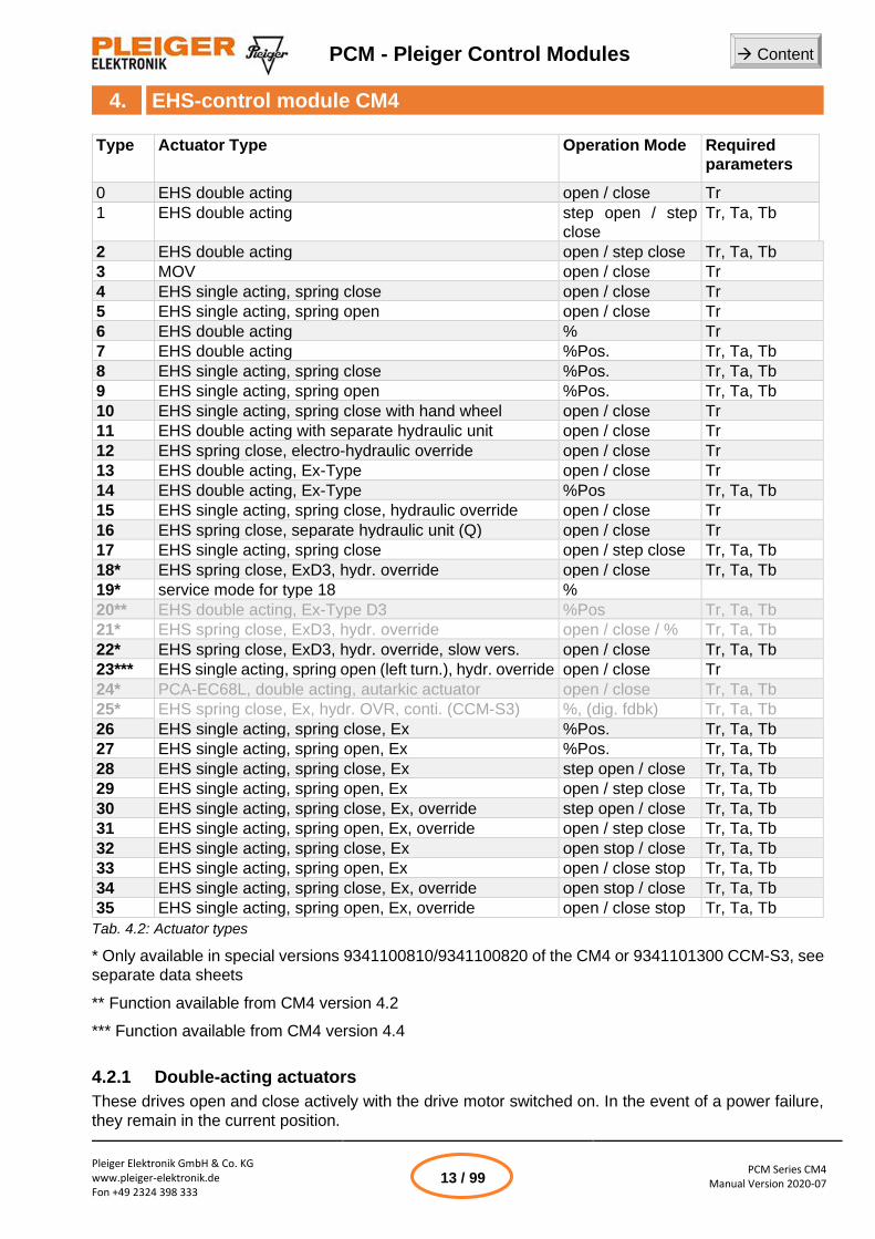
4.2 Control functions for actuators
The various control functions are required for the correct control of the different types of actuators. They
are selected and parameterised with the programming device PST, in the "Parameter Set-Up" menu
with the parameter Typ.
CAUTION Damage to the device / malfunction of the actuators
It is absolutely necessary to adapt the control function to the type of actuator as oth-
erwise correct function of the actuator is not guaranteed and the actuator or the con-
trol module can be damaged as the case may be.
NOTE Required time parameters
In addition to setting the actuator type, the specified required time parameters must
also be set. Otherwise a correct function of the drive cannot be guaranteed.
Parameter Tr Runtime (for all types of actuators)
Tr The parameter Tr defines the runtime of the drive. The adjustable number 0...520 corresponds
to a time from 0 to 520s. In general, a rather coarse setting (-5% to +30%) is sufficient, but the
time should be rather too long. Tr is used to calculate the monitoring time and also the follow-
up time.
Additional required parameters Ta and Tb, necessary for some actuator types, are explained in the
following description of the different types.
In principle, the active operation time of all actuator types is monitored from the time a run command is
issued. If the actuated position is not reached within the monitoring time, the alarm output is set and the
alarm status is signalled via the LEDs of the module.
PCM - Pleiger Control Modules → Content
4. EHS-control module CM4
Pleiger Elektronik GmbH & Co. KG www.pleiger-elektronik.de Fon +49 2324 398 333
13 / 99
PCM Series CM4 Manual Version 2020-07
Type Actuator Type Operation Mode Required
parameters
0 EHS double acting open / close Tr
1 EHS double acting step open / step
close
Tr, Ta, Tb
2 EHS double acting open / step close Tr, Ta, Tb
3 MOV open / close Tr
4 EHS single acting, spring close open / close Tr
5 EHS single acting, spring open open / close Tr
6 EHS double acting % Tr
7 EHS double acting %Pos. Tr, Ta, Tb
8 EHS single acting, spring close %Pos. Tr, Ta, Tb
9 EHS single acting, spring open %Pos. Tr, Ta, Tb
10 EHS single acting, spring close with hand wheel open / close Tr
11 EHS double acting with separate hydraulic unit open / close Tr
12 EHS spring close, electro-hydraulic override open / close Tr
13 EHS double acting, Ex-Type open / close Tr
14 EHS double acting, Ex-Type %Pos Tr, Ta, Tb
15 EHS single acting, spring close, hydraulic override open / close Tr
16 EHS spring close, separate hydraulic unit (Q) open / close Tr
17 EHS single acting, spring close open / step close Tr, Ta, Tb
18* EHS spring close, ExD3, hydr. override open / close Tr, Ta, Tb
19* service mode for type 18 %
20** EHS double acting, Ex-Type D3 %Pos Tr, Ta, Tb
21* EHS spring close, ExD3, hydr. override open / close / % Tr, Ta, Tb
22* EHS spring close, ExD3, hydr. override, slow vers. open / close Tr, Ta, Tb
23*** EHS single acting, spring open (left turn.), hydr. override open / close Tr
24* PCA-EC68L, double acting, autarkic actuator open / close Tr, Ta, Tb
25* EHS spring close, Ex, hydr. OVR, conti. (CCM-S3) %, (dig. fdbk) Tr, Ta, Tb
26 EHS single acting, spring close, Ex %Pos. Tr, Ta, Tb
27 EHS single acting, spring open, Ex %Pos. Tr, Ta, Tb
28 EHS single acting, spring close, Ex step open / close Tr, Ta, Tb
29 EHS single acting, spring open, Ex open / step close Tr, Ta, Tb
30 EHS single acting, spring close, Ex, override step open / close Tr, Ta, Tb
31 EHS single acting, spring open, Ex, override open / step close Tr, Ta, Tb
32 EHS single acting, spring close, Ex open stop / close Tr, Ta, Tb
33 EHS single acting, spring open, Ex open / close stop Tr, Ta, Tb
34 EHS single acting, spring close, Ex, override open stop / close Tr, Ta, Tb
35 EHS single acting, spring open, Ex, override open / close stop Tr, Ta, Tb
Tab. 4.2: Actuator types
* Only available in special versions 9341100810/9341100820 of the CM4 or 9341101300 CCM-S3, see
separate data sheets
** Function available from CM4 version 4.2
*** Function available from CM4 version 4.4
4.2.1 Double-acting actuators
These drives open and close actively with the drive motor switched on. In the event of a power failure,
they remain in the current position.

PCM - Pleiger Control Modules → Content
4. EHS-control module CM4
Pleiger Elektronik GmbH & Co. KG www.pleiger-elektronik.de Fon +49 2324 398 333
14 / 99
PCM Series CM4 Manual Version 2020-07
4.2.1.1 Type 0: „Open / Close“
After issuing the operation command, e.g. by pressing the command key in direction "close", the actu-
ator runs until the end position is reached or the monitoring time is exceeded.
4.2.1.2 Type 1: „Successively open / Successively close“
This operating mode corresponds largely to the open/close operating mode. During closing and open-
ing, the drive is however stopped several times for a short time to extend the travel time. In doing so,
the travel time is extended by the parameterized running time. The switch-on time (pulse time) of the
drive is at least 1s. The drive is stopped up to 10 times. The pulse and pause times Ta and Tb can be
set with the PST.
The monitoring time is extended by the pause times.
Additional parameters:
Ta Pulse time in 0,1s.
Tb Pause time in 0,1s. When closing, the duration of the first pulse is Tr/2. When opening, the
drive continues to run without pause as soon as the duration of all pulses together is greater
than Tr/2.
4.2.1.3 Type 2: „Open / Successively close“
This operating mode corresponds largely to the open/close operating mode. When opening, the actuator
runs through until the end position is reached. When closing, however, the actuator is stopped several
times for a short time to extend the closing time. The closing time is extended by the set running time,
i.e. the closing time is approximately doubled. The switch-on time (pulse time) of the drive is at least 1s.
The drive is stopped up to 10 times depending on the running time. The pulse and pause times can be
set with the PST.
When closing, the monitoring time is extended by the pause times.
Additional parameters:
Ta Pulse time in 0,1s.
Tb Pause time in 0,1s. When closing, the duration of the first pulse is Tr/2.
4.2.1.4 Type 6: „%“ (0% to 100%, position control)
In this operation mode, the drive is only operated as long as the command key is pressed or the com-
mand is present. Thus, the drive can be stopped in any position between the end positions (limit
switches). If one of the two limit switches of the actuator is actuated, the actuator is moved to the cor-
responding end position for the duration of the run-on time when the button is released. This ensures
that the drive has been moved completely into the end position when the limit switch signals this. This
function is used for throttle valves, for example.
4.2.1.5 Type 7: „%POS“ (0% to 100%, direct position control)
This operating mode is only used in conjunction with the command issued by a higher-level controller.
In this case, the higher-level control system specifies the desired position of the damper in % and the
control module automatically moves the damper to the target position. The module ignores deviations
of less than 2% from the target position.

PCM - Pleiger Control Modules → Content
4. EHS-control module CM4
Pleiger Elektronik GmbH & Co. KG www.pleiger-elektronik.de Fon +49 2324 398 333
15 / 99
PCM Series CM4 Manual Version 2020-07
If controlled by mimic or local command inputs, the actuator is only operated as long as the command
key is pressed or the command is present. Thus, the actuator can be stopped in any position between
the end positions (limit switches). If one of the two limit switches of the actuator is operated, the actuator
is moved to the corresponding end position for the duration of the follow up time when the button is
released. This ensures that the drive has been moved completely into the end position when this is
signalized by the limit switch.
Additional parameters:
Ta Specifies how much % the drive should stop on closing, before reaching the target position.
Tb Specifies how much % the drive should stop on opening, before reaching the target position.
4.2.2 Double-acting actuators with separate hydraulic unit
These drives open and close actively with the drive motor switched on. In the event of a power failure,
they remain in their current position. They have a separate hydraulic unit. The hydraulic unit and swivel
drive are connected with hydraulic pipes. This allows the actuators to be operated under particularly
unfavourable ambient conditions, e.g. under medium or at extreme temperatures. The control function
is adapted to these actuator types.
4.2.2.1 Type 11: „Open / Close“
After issuing the operation command, e.g. by pressing the command key in direction "close", the actu-
ator runs until the end position is reached or the monitoring time is exceeded.
4.2.3 Double-acting actuators in Ex type
These drives open and close actively with the drive motor switched on. In the event of a power failure,
they remain in their current position. There are drives with and without integrated starting capacitor for
the pump motor.
4.2.3.1 Type 13: „Open / Close“
After issuing the operation command, e.g. by pressing the command key in direction "close", the actu-
ator runs until the end position is reached or the monitoring time is exceeded.
This actuator can only be operated together with the capacitor module for Ex actuators (9311222810,
see also section 4.8.1).
4.2.3.2 Type 14: „%POS“ (0% to 100%, direct position control)
This operating mode is only used in conjunction with the command issued by a higher-level controller.
In this case, the higher-level control system specifies the desired position of the damper in % and the
control module automatically moves the damper to the target position. The module ignores deviations
of less than 2% from the target position.
If controlled by mimic or local command inputs, the actuator is only operated as long as the command
key is pressed or the command is present. Thus, the actuator can be stopped in any position between
the end positions (limit switches). If one of the two limit switches of the actuator is operated, the actuator
is moved to the corresponding end position for the duration of the follow up time when the button is
released. This ensures that the drive has been moved completely into the end position when this is
signalized by the limit switch.
This actuator can only be operated together with the capacitor module for Ex actuators (9311222810,
see also section 4.8.1).

PCM - Pleiger Control Modules → Content
4. EHS-control module CM4
Pleiger Elektronik GmbH & Co. KG www.pleiger-elektronik.de Fon +49 2324 398 333
16 / 99
PCM Series CM4 Manual Version 2020-07
Additional parameters:
Ta Specifies how much % the drive should stop on closing, before reaching the target position.
Tb Specifies how much % the drive should stop on opening, before reaching the target position.
4.2.3.3 Type 20: „%POS“ design D3 (0% to 100%, direct position control)
This operating mode is only used in conjunction with the command issued by a higher-level controller.
In this case, the higher-level control system specifies the desired position of the damper in % and the
control module automatically moves the damper to the target position. The module ignores deviations
of less than 2% from the target position.
If controlled by mimic or local command inputs, the actuator is only operated as long as the command
key is pressed or the command is present. Thus, the actuator can be stopped in any position between
the end positions (limit switches). If one of the two limit switches of the actuator is operated, the actuator
is moved to the corresponding end position for the duration of the follow up time when the button is
released. This ensures that the drive has been moved completely into the end position when this is
signalized by the limit switch.
This type of drive does not require an external capacitor module, as the starting capacitor for the
pump motor is always installed in the pressure-resistant encapsulated housing of the drive. There is no
contact-based digital end position signal „open / closed“. The end position signal „open / closed“ is
formed from the analogue position feedback signal (4-20mA).
Function available from CM4 firmware version 4.2!
Additional parameters:
Ta Specifies how much % the drive should stop on closing, before reaching the target position.
Tb Specifies how much % the drive should stop on opening, before reaching the target position.
4.2.4 Single-acting actuators
Single-acting actuators are always driven in one direction by spring force, depending on the actuator
type in the direction open or closed. This ensures that in the event of a power failure, the actuator is
always driven in the preferred, safe direction, depending on the application.
4.2.4.1 Type 4: Spring close „Open / Close“
This drive opens actively with the drive motor switched on. The closing process takes place via spring
force. In case of power failure the drive closes.
After issuing the operation command, e.g. by pressing the command key in direction "close", the actu-
ator runs until the end position is reached or the monitoring time is exceeded.
4.2.4.2 Type 5: Spring open „Open / Close“
This drive closes actively with the drive motor switched on. The opening process takes place via spring
force. In case of power failure the drive opens. Hint: Right rotating axis.
After issuing the operation command, e.g. by pressing the command key in direction "close", the actu-
ator runs until the end position is reached or the monitoring time is exceeded.

PCM - Pleiger Control Modules → Content
4. EHS-control module CM4
Pleiger Elektronik GmbH & Co. KG www.pleiger-elektronik.de Fon +49 2324 398 333
17 / 99
PCM Series CM4 Manual Version 2020-07
4.2.4.3 Type 8: Spring close „%POS“ (0% to 100%, direct position control)
This drive opens actively with the drive motor switched on. The closing process takes place via spring
force. In case of power failure the drive closes.
This operating mode is only used in conjunction with the command issued by a higher-level controller.
In this case, the higher-level control system specifies the desired position of the damper in % and the
control module automatically moves the damper to the target position. The module ignores deviations
of less than 2% from the target position.
If controlled by mimic or local command inputs, the actuator is only operated as long as the command
key is pressed or the command is present. Thus, the actuator can be stopped in any position between
the end positions (limit switches). If one of the two limit switches of the actuator is operated, the actuator
is moved to the corresponding end position for the duration of the follow up time when the button is
released. This ensures that the drive has been moved completely into the end position when this is
signalized by the limit switch.
Additional parameters:
Ta Specifies how much % the drive should stop on closing, before reaching the target position.
Tb Specifies how much % the drive should stop on opening, before reaching the target position.
4.2.4.4 Type 9: Spring open „%POS“ (0% to 100%, direct position control)
This drive closes actively with the drive motor switched on. The opening process takes place via spring
force. In case of power failure the drive opens. Hint: Right rotating axis
This operating mode is only used in conjunction with the command issued by a higher-level controller.
In this case, the higher-level control system specifies the desired position of the damper in % and the
control module automatically moves the damper to the target position. The module ignores deviations
of less than 2% from the target position.
If controlled by mimic or local command inputs, the actuator is only operated as long as the command
key is pressed or the command is present. Thus, the actuator can be stopped in any position between
the end positions (limit switches). If one of the two limit switches of the actuator is operated, the actuator
is moved to the corresponding end position for the duration of the follow up time when the button is
released. This ensures that the drive has been moved completely into the end position when this is
signalized by the limit switch.
Additional parameters:
Ta Specifies how much % the drive should stop on closing, before reaching the target position.
Tb Specifies how much % the drive should stop on opening, before reaching the target position.
4.2.4.5 Type 17: Spring close „Open / Successively close“
This drive opens actively with the drive motor switched on. The closing process takes place via spring
force. In case of power failure the drive closes.
This operating mode corresponds largely to the open/close operating mode. When opening, the actuator
runs through until the end position is reached. When closing, however, the actuator is stopped several
times for a short time to extend the closing time. The closing time is extended by the set running time,
i.e. the closing time is approximately doubled. The switch-on time (pulse time) of the drive is at least 1s.
The drive is stopped up to 10 times depending on the running time. The pulse and pause times can be
set with the PST.

PCM - Pleiger Control Modules → Content
4. EHS-control module CM4
Pleiger Elektronik GmbH & Co. KG www.pleiger-elektronik.de Fon +49 2324 398 333
18 / 99
PCM Series CM4 Manual Version 2020-07
When closing, the monitoring time is extended by the pause times.
Additional parameters:
Ta Pulse time in 0,1s.
Tb Pause time in 0,1s. When closing, the duration of the first pulse is Tr/2.
4.2.5 Single-acting actuators with separate hydraulic unit
These drives open and close actively with the drive motor switched on. In the event of a power failure,
they remain in their current position. They have a separate hydraulic unit. The hydraulic unit and swivel
drive are connected with hydraulic pipes. This allows the actuators to be operated under particularly
unfavourable ambient conditions, e.g. under medium or at extreme temperatures. The control function
is adapted to these actuator types.
4.2.5.1 Type 16: Spring close „Open / Close“
This drive opens actively with the drive motor switched on. The closing process takes place via spring
force. In case of power failure the drive closes.
After issuing the operation command, e.g. by pressing the command key in direction "close", the actu-
ator runs until the end position is reached or the monitoring time is exceeded.
4.2.6 Single-acting actuator with extended operation by handwheel
This actuator corresponds to a normal spring closing actuator. By means of a handwheel it can be
opened manually. This operating state is permitted and is not reported as an error by the control module.
To close the manually opened actuator again, it must first be fully opened electrically. This function is
performed automatically by the control module.
4.2.6.1 Type 10: Spring close „Open / Close“
After issuing the operation command, e.g. by pressing the command key in direction "close", the actu-
ator runs until the end position is reached or the monitoring time is exceeded.
4.2.7 Single-acting actuators with extended operation by hand pump
These drives correspond to spring-closing or spring-opening drives. With the help of a hand pump and a manual valve, these drives can also be manually closed or opened against the direction acting in the spring force. This manually changed operating state is permitted and is not reported as an error by the control module.
4.2.7.1 Type 12: Spring close "Open / Close" with electrically unlockable manual valve
This type of actuator corresponds to a normal spring closing actuator, but can be opened by means of
a manually operated valve and a hand pump. To close a manually opened actuator, the manually closed
manual valve is first opened by the control module and then closed again by spring force.
After issuing the operation command, e.g. by pressing the command key in direction "close", the actu-
ator runs until the end position is reached or the monitoring time is exceeded.
4.2.7.2 Type 15: Spring close "Open / Close" with hydraulically operated hand valve
This actuator corresponds to a normal spring closing actuator, but can be opened manually with a hand
pump and closed again with a manually operated valve. To close a manually opened actuator, the pump

PCM - Pleiger Control Modules → Content
4. EHS-control module CM4
Pleiger Elektronik GmbH & Co. KG www.pleiger-elektronik.de Fon +49 2324 398 333
19 / 99
PCM Series CM4 Manual Version 2020-07
must run for a few seconds with the solenoid valve closed to build up pressure. This function is per-
formed automatically by the control module.
After issuing the operation command, e.g. by pressing the command key in direction "close", the actu-
ator runs until the end position is reached or the monitoring time is exceeded.
4.2.7.3 Type 23: Spring open "Open / Close" with hydraulically operated hand valve
This actuator corresponds to a normal spring opening actuator, but can be closed manually with a hand
pump and opened again with a manually operated valve. To open a manually closed actuator, the pump
must run for a few seconds with the solenoid valve closed to build up pressure. This function is per-
formed automatically by the control module.
After issuing the operation command, e.g. by pressing the command key in direction "close", the actu-
ator runs until the end position is reached or the monitoring time is exceeded.
Function available from CM4 firmware version 4.4!
4.2.8 Single-acting actuator in Ex type
4.2.8.1 Type 26: Spring close „%POS Ex“ (0% to 100%, direct position control, Ex type)
This drive opens actively with the drive motor switched on. The closing process takes place via spring
force. In case of power failure the drive closes.
When a command is given by a higher-ranking control system, the control system specifies the desired
position of the damper in % and the control module automatically moves the damper to the target posi-
tion. If there is a deviation of more than 2% from the target position, the module readjusts the position.
If controlled by mimic or local command inputs, the actuator is only driven as long as the command
button is pressed or the command is present. Thus, the actuator can be stopped in any position between
the end positions OPEN/CLOSED. If one of the two end positions of the actuator is signalled, the actu-
ator is moved to the corresponding end position for the duration of the run-on time when the button is
released. This ensures that the drive has moved completely into the end position when this is signalled.
A PCM-ExE module is required to operate the motor. The end position signal OPEN/CLOSED is formed
from the analogue position feedback signal (4-20mA).
As with all continuously controllable „%Pos“ actuators, the parameters Ta and Tb are used to increase
the positioning accuracy and can be determined by means of a learning run.
Additional parameters:
Ta Specifies how much % of the travel distance the control output should be switched off before
reaching the target position while closing ("derivative action time on closing").
Tb Specifies how much % of the travel distance the control output should be switched off before
reaching the target position while opening ("derivative action time when opening").
4.2.8.2 Type 27: Spring open „%POS Ex“ (0% to 100%, direct position control, Ex type)
This drive closes actively with the drive motor switched on. The opening process takes place via spring
force. In case of power failure the drive opens.
When a command is given by a higher-ranking control system, the control system specifies the desired
position of the damper in % and the control module automatically moves the damper to the target posi-
tion. If there is a deviation of more than 2% from the target position, the module readjusts the position.

PCM - Pleiger Control Modules → Content
4. EHS-control module CM4
Pleiger Elektronik GmbH & Co. KG www.pleiger-elektronik.de Fon +49 2324 398 333
20 / 99
PCM Series CM4 Manual Version 2020-07
If controlled by mimic or local command inputs, the actuator is only driven as long as the command
button is pressed or the command is present. Thus, the actuator can be stopped in any position between
the end positions OPEN/CLOSED. If one of the two end positions of the actuator is signalled, the actu-
ator is moved to the corresponding end position for the duration of the run-on time when the button is
released. This ensures that the drive has moved completely into the end position when this is signalled.
A PCM-ExE module is required to operate the motor. The end position signal OPEN/CLOSED is formed
from the analogue position feedback signal (4-20mA).
As with all continuously controllable „%Pos“ actuators, the parameters Ta and Tb are used to increase
the positioning accuracy and can be determined by means of a learning run.
Additional parameters:
Ta Specifies how much % of the travel distance the control output should be switched off before
reaching the target position while closing ("derivative action time on closing").
Tb Specifies how much % of the travel distance the control output should be switched off before
reaching the target position while opening ("derivative action time when opening").
4.2.8.3 Type 28: Spring close „Successively open (step by step) / Close“, Ex type
This drive opens actively with the drive motor switched on. During opening, the drive is stopped several
times for a short time in order to extend the operating time. The closing process is by spring force. The
actuator closes in case of power failure.
When opening (active direction), the actuator is stopped several times for a short time to extend the
travel time. Two operating modes are possible:
1) A motor switch-on time (pulse time) is specified with Ta, which is at least 0.5s. Tb specifies the
respective stop time to be inserted between the pulses in 0.1s.
2) Alternatively, parameter Tb can be used to specify a total pause time in seconds by which the
running time of the drive is to be extended. In this case, the parameter Ta must be set to zero.
The pulse and pause times Ta and Tb can be set with the PST
As well drives with 400V Ex-d motors and single-phase motors with an additional PCM-ExE module can
be controlled.
Additional parameters:
Mode 1 (Ta ≠ 0) Mode 2 (Ta = 0)
Ta Pulse time in 0,1s (min. 0,5s) 0
Tb Pulse time in 0,1s. Total pause in s (is split into 5 / 10 parts)
4.2.8.4 Type 30: Spring close „Successively open (step by step) / Close“, Ex type, override
The drive corresponds functionally to the previously mentioned type 28, but additionally has a so-called
override function.
The actuator has a hydraulic hand pump that can override a valve provided by the customer. Leaving
the close end position via the hand pump is recognized as an override case and tolerated by the module.
After sending a new command, the module can unlock the valve again and return to automatic mode.
The parameters are identical in type and function to the predecessor type 28.

PCM - Pleiger Control Modules → Content
4. EHS-control module CM4
Pleiger Elektronik GmbH & Co. KG www.pleiger-elektronik.de Fon +49 2324 398 333
21 / 99
PCM Series CM4 Manual Version 2020-07
Additional parameters:
Mode 1 (Ta ≠ 0) Mode 2 (Ta = 0)
Ta Pulse time in 0,1s (min. 0,5s) 0
Tb Pulse time in 0,1s. Total pause in s (is split into 5 / 10 parts)
4.2.8.5 Type 29: Spring open „Open / Successively close (step by step)“, Ex type
This drive closes actively with the drive motor switched on. During closing, the drive is stopped several
times for a short time in order to extend the closing time. The opening process is by spring force. The
actuator opens in case of power failure.
Two operating modes are possible:
1) A motor switch-on time (pulse time) is specified with Ta, which is at least 0.5s. Tb specifies the
respective stop time to be inserted between the pulses in 0.1s.
2) Alternatively, parameter Tb can be used to specify a total pause time in seconds by which the
running time of the drive is to be extended. In this case, the parameter Ta must be set to zero.
The pulse and pause times Ta and Tb can be set with the PST.
As well drives with 400V Ex-d motors and single-phase motors with an additional PCM-ExE module can
be controlled.
Additional parameters:
Mode 1 (Ta ≠ 0) Mode 2 (Ta = 0)
Ta Pulse time in 0,1s (min. 0,5s) 0
Tb Pulse time in 0,1s. Total pause in s (is split into 5 / 10 parts)
4.2.8.6 Type 31: Spring open „Open / Successively close (step by step)“, Ex type, override
The drive corresponds functionally to the previously mentioned type 29, but additionally has a so-called
override function.
The actuator has a hydraulic hand pump that can override a valve provided by the customer. Leaving
the open end position via the hand pump is recognized as an override case and tolerated by the module.
After sending a new command, the module can unlock the valve again and return to automatic mode.
The parameters are identical in type and function to the predecessor type 29.
Additional parameters:
Mode 1 (Ta ≠ 0) Mode 2 (Ta = 0)
Ta Pulse time in 0,1s (min. 0,5s) 0
Tb Pulse time in 0,1s. Total pause in s (is split into 5 / 10 parts)

PCM - Pleiger Control Modules → Content
4. EHS-control module CM4
Pleiger Elektronik GmbH & Co. KG www.pleiger-elektronik.de Fon +49 2324 398 333
22 / 99
PCM Series CM4 Manual Version 2020-07
4.2.8.7 Type 32: Spring close „Open with pause / Close“, Ex type
This drive opens actively with the drive motor switched on. The closing process takes place via spring
force. In case of power failure the drive closes.
When opening (active direction), the actuator is stopped after a time (Ta) to be set (e.g. to be able to fill
pipelines with medium first), before the actuator is fully opened after a pause time (Tb).
The pulse and pause times Ta and Tb can be set with the PST
As well drives with 400V Ex-d motors and single-phase motors with an additional PCM-ExE module can
be controlled.
Additional parameters:
Ta First opening step in 0.1s (max. 25s)
Tb Pause in active direction in s (max. 255s)
4.2.8.8 Type 34: Spring close „Open with pause / Close“, Ex type, override
The drive corresponds functionally to the previously mentioned type 32, but additionally has a so-called
override function.
The actuator has a hydraulic hand pump that can override a valve provided by the customer. Leaving
the close end position via the hand pump is recognized as an override case and tolerated by the module.
After sending a new command, the module can unlock the valve again and return to automatic mode.
The parameters are identical in type and function to the predecessor type 32.
Additional parameters:
Ta First opening step in 0.1s (max. 25s)
Tb Pause in active direction in s (max. 255s)
4.2.8.9 Type 33: Spring open „Open / Close with pause“, Ex type
This drive closes actively with the drive motor switched on. The open process takes place via spring
force. In case of power failure the drive opens.
When closind (active direction), the actuator is stopped after a time (Ta) to be set, before the actuator
is fully closed after a pause time (Tb).
The pulse and pause times Ta and Tb can be set with the PST
As well drives with 400V Ex-d motors and single-phase motors with an additional PCM-ExE module can
be controlled.
Additional parameters:
Ta First closing step in 0.1s (max. 25s)
Tb Pause in active direction in s (max. 255s)

PCM - Pleiger Control Modules → Content
4. EHS-control module CM4
Pleiger Elektronik GmbH & Co. KG www.pleiger-elektronik.de Fon +49 2324 398 333
23 / 99
PCM Series CM4 Manual Version 2020-07
4.2.8.10 Type 35: Spring open „Open / Close with pause“, Ex type, override
The drive corresponds functionally to the previously mentioned type 33, but additionally has a so-called
override function.
The actuator has a hydraulic hand pump that can override a valve provided by the customer. Leaving
the open end position via the hand pump is recognized as an override case and tolerated by the module.
After sending a new command, the module can unlock the valve again and return to automatic mode.
The parameters are identical in type and function to the predecessor type 33.
Additional parameters:
Ta First closing step in 0.1s (max. 25s)
Tb Pause in active direction in s (max. 255s)
4.2.9 MOV, Motor valve
This drive behaves like a double-acting drive, but in contrast to this, it automatically switches off the
drive motor when the end position is reached. The control module always leaves the power supply
switched on during normal operation and only disconnects the drive in case of a fault.
4.2.9.1 Type 3: „Open / Close“
After issuing the operation command, e.g. by pressing the command key in direction "close", the actu-
ator runs until the end position is reached or the monitoring time is exceeded.
4.3 Teach-in
To determine the parameters Tr, Ta and Tb a teach-in may be used. Please look at chapter 16.5.
4.4 Indicators
4.4.1 Status LED
Three LEDs (red, yellow, green) indicate the operating status of the drive and the control
module. The red and green LEDs indicate the operating status of the drive.
LED red LED green Meaning
on off Actuator closed in end position
on blinking 1/s Actuator closed in end position, open command received
off blinking 1/s Actuator moves in the open direction, leave the closed end position
off on Open actuator in end position
blinking 1/s on Actuator open in end position, close command received
blinking 1/s off Actuator moves in the close direction, leave the end position open
blinking 2/s on / off End position closed not reached within the set running time
on / off blinking 2/s Open end position not reached within the set running time
blinking 2/s blinking 2/s no end position detected when starting the module
blinking 4/s blinking 4/s invalid feedback, open and closed at the same time
Additionally for actuator types No. 10, 12, 15 (spring-close, override function):
blinking1/2s off Close command, opened manually, open end position not reached

PCM - Pleiger Control Modules → Content
4. EHS-control module CM4
Pleiger Elektronik GmbH & Co. KG www.pleiger-elektronik.de Fon +49 2324 398 333
24 / 99
PCM Series CM4 Manual Version 2020-07
blinking1/2s on Close command, fully opened manually
Additionally for actuator type no.23 (spring-open, override function
off blinking 1/2s Open command, manually closed,
End position closed not reached
on blinking 1/2s Open command, completely closed manually
Tab. 4.2: CM4 LED red/green
The yellow LED is used to indicate the operating status of the control module.
LED yellow Function
ON 230V AC supply voltage missing or fuse defective.
OFF Supply voltage available, no (valid) data on the local bus.
Blinking Supply voltage available and valid telegrams on the local data bus, but
this control module is not addressed.
Flickers Supply voltage available, communication with bus interface is active.
short
flash
~ 3s
The short, quick flashing (other signals are suppressed) signals the ac-
tivation of "Local Override".
The flashing is limited to 3s after activation.
short
flash
~ 3s
The short, quick flashing (other signals are suppressed) signals the ac-
tivation of "Local Stop" (only possible with D drive types) [see Chapter
4.1.3].
The flashing is limited to 5s after activation.
Tab. 4.3: CM4 LED yellow
4.4.2 Start reports and self-test
Directly after the program has started up, the module displays the last “reset“ cause by illuminating one
or two LED briefly. The module subsequently carries out a short self-test. In the event that the self-test
is not carried out successfully, the yellow LED will start to flash.
Once the self-test has been carried out successfully, the normal status display will start up.
red yellow green Meaning
Start after complete power fail
Start after low voltage
Start after hardware or software reset
Start after runtime violation (watchdog)
Tab. 4.6: CM4 LED start reports and self-test
Subsequently the module starts a short self-test. If this self-test fails the yellow LED starts blinking while
the red and green LED are turned off. Apart from that the CM4 has no function.

PCM - Pleiger Control Modules → Content
4. EHS-control module CM4
Pleiger Elektronik GmbH & Co. KG www.pleiger-elektronik.de Fon +49 2324 398 333
25 / 99
PCM Series CM4 Manual Version 2020-07
4.5 Wire break and short circuit detection
The mimic inputs as well as the inputs for the feedback signals can be parameterized in such a way
that a wire break or a short circuit can be detected. The CM4 measures the signal voltage, calculates
the relation between supply voltage and signal voltage and finally compares the result with predefined
limits. The required signal voltages are adjusted by parallel and series resistor as usual.
4.5.1 Mimic Inputs
SHORT < - -
ON < - - - - - - - - - - >
OFF < - - - - - - - - >
BREAK - - >
Ub 0 1 2 3 4 5 6 7 8 9 10 11 12 13 14 15 16 17 18 19 20 21 22 23 24
Fig. 4.3: Wire break and short circuit detection of the mimic inputs
Break On Short
on threshold (Ub = 24V) 1,9V 12,0V 22,3V
off threshold (Ub = 24V) 2,2V 11,4V 22,0V
on threshold in % of Ub 7,9% 50,2% 92,8%
off threshold in % of Ub 9,4% 47,5% 91,6%
Resistor min. 10kΩ - 1kΩ
Resistor max. 35kΩ - 5kΩ
Recommend resistor 22kΩ - 2,2kΩ
The tolerance of the threshold voltages is +- 500mV.
Tab. 4.4: Wire break and short circuit detection of the mimic inputs
The function of the break or short detection depends on the inverted or non-inverted function of the
mimic inputs.
Standard command input
The reaction of the CM4 on the four different input levels depends on the previous command state and
the duration of the input level.
Input Level Current State Delay New Command Alarm
1. ON OFF 0,2s ON NO
2. OFF ON 0,2s OFF NO
3. BREAK ON / OFF 2s SAME BREAK
4. ON / OFF BREAK / SHORT 10s ON / OFF NO
5. SHORT ON / OFF 2s SAME SHORT
6. BREAK / SHORT SHORT / BREAK 10s SAME BREAK / SHORT
Tab. 4.5: Standard command input CM4
State: current state, before responding to the input signal
Command: command that results from current state and input signal
Fig. 4.2: Circuit diagram input circuit

PCM - Pleiger Control Modules → Content
4. EHS-control module CM4
Pleiger Elektronik GmbH & Co. KG www.pleiger-elektronik.de Fon +49 2324 398 333
26 / 99
PCM Series CM4 Manual Version 2020-07
Alarm: the break or short alarms are indicated by error number 4 and the alarm contact of the
CM4 additionally the bits 3 and 4 of the status byte are both set additionally the local LED
indicate the error by very fast blinking (see chapter 4.4)
e.g.
1. if the input level changes from Off to On, the new command is created with 0,2s delay.
5. if the input level changes from On or Off to Short the Short alarm will be raised with 2s delay,
whereas the command will stay unchanged.
Inverted command input
If the inverted operation mode is set the meaning of the command input levels On and Off is inverted.
A low level will set the command whereas a high level will not. In case of a break level the alarm is
raised and also the command is set. This is the typical behaviour of closed current circuits.
Input Level Current State Delay New Command Alarm
1. OFF OFF 0,2s ON NO
2. ON ON 0,2s OFF NO
3. BREAK ON / OFF 2s ON BREAK
4. ON / OFF BREAK / SHORT 10s ON / OFF NO
5. SHORT ON / OFF 2s SAME SHORT
6. BREAK / SHORT SHORT / BREAK 10s ON / SAME BREAK / SHORT
Tab. 4.6: Inverted command input CM4
WARNING Module / actuator behavior on inverted command inputs
If the "Invert" parameter is set for one or more command inputs, the module recog-
nizes a missing "high signal" (24 VDC) at the corresponding input as a permanent
command. All other commands, via local buttons or from the BI, might be blocked.
Additional commissioning features controlled by local buttons doesn’t work in this
case, too (e.g. showing the firmware version on BI-display, address setting, and so
on).
4.5.2 Position feedback inputs
SHORT < - -
ON < - - - - - - - - - >
OFF < - - - - - - - - >
BREAK - - >
Ub 0 1 2 3 4 5 6 7 8 9 10 11 12 13 14 15 16 17 18 19 20 21 22 23 24

PCM - Pleiger Control Modules → Content
4. EHS-control module CM4
Pleiger Elektronik GmbH & Co. KG www.pleiger-elektronik.de Fon +49 2324 398 333
27 / 99
PCM Series CM4 Manual Version 2020-07
Fig. 4.4: Wire break and short circuit monitoring of the feedback inputs
Break On Short
on threshold (Ub = 24V) 22,0V 11,4V 1,9V
off threshold (Ub = 24V) 21,7V 11,7V 2,2V
on threshold in % of Ub 91,7% 47,6% 7,8%
off threshold in % of Ub 90,4% 48,8% 9,2%
Resistor min. 10kΩ - 1kΩ
Resistor max. 35kΩ - 5kΩ
Recommend resistor 22kΩ - 2,2kΩ
The tolerance of the threshold voltages is +- 500mV.
Tab. 4.7: Wire break / short circuit monitoring of the feedback inputs
A break or short is indicated to the BI as fault no. 3 (1 of N faults). Additionally the alarm contact opens.
4.5.3 Display of wire break and short circuit errors of the mimic inputs
The BI displays an "invalid command" message if a wire break or short circuit is detected. In addition,
the error is indicated with the help of a special flashing rhythm of the red or green LED on the CM4, in
that these flashing signals correspond to the above. Blink signals are superimposed. The red LED is
used to indicate errors in the mimic input "close" and, accordingly, the green LED for the input "open".
The states of the actuator and the error states of the mimic inputs can be displayed and recorded sim-
ultaneously. This also applies to two simultaneous errors e.g. runtime error and wire break. Broken wire
and short circuit errors are signaled in the same form.
Standard display Display at Break / Short t= 0,0s 0,5s 1,0s 1,5s 2s
OFF short flash 1/s - - - - - .
ON permanent flickering - - - - - - - - - - - - - - - - - - - - - - - - - - -
ON-OFF-Flash 1/s 0,5s off, 0,5s Flickering etc. - - - - - - - - - - - - - - - - - -
ON-OFF-Flash 2/s 0,25s off, 0,25s Flickering, etc. - - - - - - - - - - - - - - -
Tab. 4.8: Display wire break- / short circuit errors
Example: signals under normal conditions
LED red LED green Definition
Actuator closed in end position
Actuator open in end position, close command received
Actuator opened in end position
Example: The same signals for "wire break error of the mimic input" close "
LED red LED green Definition
Actuator closed in end position + wire break mimic "close"
End pos. open +close command + wire break mimic "close"
Actuator opened in end position + wire break mimic "close“
Tab. 4.9: Example display wire break
Fig. 4.5: Circuit diagram feedback input

PCM - Pleiger Control Modules → Content
4. EHS-control module CM4
Pleiger Elektronik GmbH & Co. KG www.pleiger-elektronik.de Fon +49 2324 398 333
28 / 99
PCM Series CM4 Manual Version 2020-07
4.6 Lamp test
Terminal 3 of the local bus is used as a lamp test input. As soon as 24V is applied, the 3 LEDs of the
module light up and in addition the two message outputs LED open and LED closed are switched on.
4.7 Alarm output
After a successful self-test, the alarm output is closed. As soon as a fault occurs, the output is opened.
The output is not closed again until all faults have been eliminated.
Faults that open the alarm contact:
• 24 VDC or 230 VAC power failure
• Invalid / impermissible position message from the actuator
• Invalid signal voltages at the inputs of the position message (wire break and short)
• Invalid signal voltages at the mimic command inputs (wire break and short)
• Drive timed out
If the special function "alarm out = local ctrl" is set, the alarm relay is not used for alarm output but only
for signaling the position of the "local / remote" switch.

PCM - Pleiger Control Modules → Content
4. EHS-control module CM4
Pleiger Elektronik GmbH & Co. KG www.pleiger-elektronik.de Fon +49 2324 398 333
29 / 99
PCM Series CM4 Manual Version 2020-07
4.8 Terminal assignment
Fig. 4.6: Side view CM4
Tab. 4.10: Terminal assignment CM4
CAUTION Damage to the device / malfunction of the actuators
PRINCIPALLY ONLY apply the 230 VAC supply voltages to the terminals that are
provided. Otherwise the modules may be damaged or destroyed.
13 FB-conti E position signal (4..20mA) (optional)
14 N A common power
15 L-close A power output: pump close / solenoid valve / pump run
16 L-open A power output: pump open / pump open / pump direction
9 FB-closed E feedback closed, 0V = closed, internal pull up
10 FB-opened E feedback opened, 0V = opened, internal pull up
11 0V A DC power supply for position sensors
12 24V A DC power supply for position sensors
1 LED-opened A drive open, to mimic diagram
2 LED-closed A drive closed, to mimic diagram
3 CMD-open E command open, from mimic diagram
4 CMD-close E command close, from mimic diagram
5 N E drive supply voltage 230V AC max. 3,15A
6 L E drive supply voltage 230V AC max. 3,15A
7 Alarm
A contact opens in case of error
8 A
Fig. 4.7: Terminal CM4
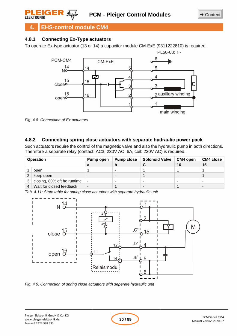
PCM - Pleiger Control Modules → Content
4. EHS-control module CM4
Pleiger Elektronik GmbH & Co. KG www.pleiger-elektronik.de Fon +49 2324 398 333
30 / 99
PCM Series CM4 Manual Version 2020-07
4.8.1 Connecting Ex-Type actuators
To operate Ex-type actuator (13 or 14) a capacitor module CM-ExE (9311222810) is required.
Fig. 4.8: Connection of Ex actuators
4.8.2 Connecting spring close actuators with separate hydraulic power pack
Such actuators require the control of the magnetic valve and also the hydraulic pump in both directions.
Therefore a separate relay (contact: AC3, 230V AC, 6A, coil: 230V AC) is required.
Operation Pump open Pump close Solonoid Valve CM4 open CM4 close
a b C 16 15
1 open 1 - 1 1 1
2 keep open - - 1 - 1
3 closing, 80% oft he runtime - - - - -
4 Wait for closed feedback - 1 - 1 -
Tab. 4.11: State table for spring close actuators with seperate hydraulic unit
Fig. 4.9: Connection of spring close actuators with seperate hydraulic unit
„C“
„b“
„a“

PCM - Pleiger Control Modules → Content
4. EHS-control module CM4
Pleiger Elektronik GmbH & Co. KG www.pleiger-elektronik.de Fon +49 2324 398 333
31 / 99
PCM Series CM4 Manual Version 2020-07
4.9 Technical data
Technical Data
Fuse DC self-resetting fuse, 500mA - 1100mA
Supply voltage AC 230 VAC, ±20%
Fuse AC 2 x 3,15AT fuse (5 x 20 mm)
Analog input position 4..20mA = 0..100%, deviation ±1%, resistance 249Ω
LED-open / -close semiconductor high side switches, +24V max. load 150mA, short cir-
cuit proof
Terminal screw- or push-in spring connection max. 2,5mm²
Tab. 4.12: Technical Data CM4
* The current consumption of the feedback modules used in the EHS, e.g. OC3 and the currents output
via the mimic outputs X1, Pin1 and Pin2 must be added to the current consumption of the module.
.
The miniature fuses for AC power supply are accessible at the lower side of the casing.
To exchange the fuses the casing has to be removed from the hat-rail. The fuse holder
can be opened by means of a screw driver
Fig. 4.10: Fuses CM4
B = 22,5 H = 105 T = 115
(mm)
IP20 -25°Cxxx
-xxx
55°Cxxx
≤ 40mA
+ external
load *
24 VDC
+30%
-25%
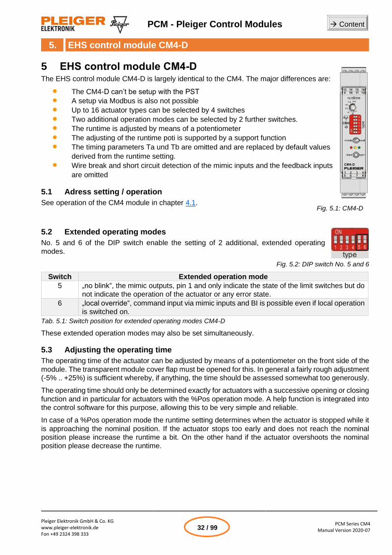
PCM - Pleiger Control Modules → Content
5. EHS control module CM4-D
Pleiger Elektronik GmbH & Co. KG www.pleiger-elektronik.de Fon +49 2324 398 333
32 / 99
PCM Series CM4 Manual Version 2020-07
5 EHS control module CM4-D The EHS control module CM4-D is largely identical to the CM4. The major differences are:
• The CM4-D can’t be setup with the PST
• A setup via Modbus is also not possible
• Up to 16 actuator types can be selected by 4 switches
• Two additional operation modes can be selected by 2 further switches.
• The runtime is adjusted by means of a potentiometer
• The adjusting of the runtime poti is supported by a support function
• The timing parameters Ta und Tb are omitted and are replaced by default values
derived from the runtime setting.
• Wire break and short circuit detection of the mimic inputs and the feedback inputs
are omitted
5.1 Adress setting / operation
See operation of the CM4 module in chapter 4.1.
5.2 Extended operating modes
No. 5 and 6 of the DIP switch enable the setting of 2 additional, extended operating
modes.
Fig. 5.2: DIP switch No. 5 and 6
Switch Extended operation mode
5 „no blink“, the mimic outputs, pin 1 and only indicate the state of the limit switches but do
not indicate the operation of the actuator or any error state.
6 „local override“, command input via mimic inputs and BI is possible even if local operation
is switched on.
Tab. 5.1: Switch position for extended operating modes CM4-D
These extended operation modes may also be set simultaneously.
5.3 Adjusting the operating time
The operating time of the actuator can be adjusted by means of a potentiometer on the front side of the
module. The transparent module cover flap must be opened for this. In general a fairly rough adjustment
(-5% .. +25%) is sufficient whereby, if anything, the time should be assessed somewhat too generously.
The operating time should only be determined exactly for actuators with a successive opening or closing
function and in particular for actuators with the %Pos operation mode. A help function is integrated into
the control software for this purpose, allowing this to be very simple and reliable.
In case of a %Pos operation mode the runtime setting determines when the actuator is stopped while it
is approaching the nominal position. If the actuator stops too early and does not reach the nominal
position please increase the runtime a bit. On the other hand if the actuator overshoots the nominal
position please decrease the runtime.
Fig. 5.1: CM4-D

PCM - Pleiger Control Modules → Content
5. EHS control module CM4-D
Pleiger Elektronik GmbH & Co. KG www.pleiger-elektronik.de Fon +49 2324 398 333
33 / 99
PCM Series CM4 Manual Version 2020-07
5.3.1 Calibration of the operating time
• Set the operating time to maximum (r.h. limit stop).
• Move the actuator from the closed position to the open position by selecting the “local” operation
mode and pushing the command key in the direction of “open”.
• Once the actuator has opened completely, push the command key again in the
direction of “open“ and hold depressed. Now slowly reduce the operating time until
the red LED also starts blinking. If both LED are blinking, the time
has been adjusted correctly
5.4 Control functions
The control function that is required for the various types of actuators can be selected
with the assistance of the first 4 DIP switches in the front of the control module housing.
For this the transparent module cover flap must be opened.
To accept the new type the module has to be reset.
CAUTION Damage to the device / malfunction of the actuators
It is absolutely necessary to adapt the control function to the type of actuator as oth-
erwise correct function of the actuator is not guaranteed and the actuator or the con-
trol module can be damaged as the case may be. Please select the correct control
function before turning on the CM4-D.
The actuator types 0…15 correspond to the CM4 (see chapter 4.2).
Type Type of actuator Operation mode Runtime Switch
1 2 3 4
0 EHS double acting open / close 4s..260s 0 0 0 0
1 EHS double acting step open / close 4s..260s 1 0 0 0
2 EHS double acting open / step close 4s..260s 0 1 0 0
3 MOV open / close 4s..260s 1 1 0 0
4 EHS single acting, spring close open / close 4s..260s 0 0 1 0
5 EHS single acting, spring open open / close 4s..260s 1 0 1 0
6 EHS double acting % 4s..260s 0 1 1 0
7 EHS double acting %Pos 4s..260s 1 1 1 0
8 EHS single acting, spring close %Pos 4s..260s 0 0 0 1
9 EHS single acting, spring open %Pos 4s..260s 1 0 0 1
10 EHS single acting, spring close with handwheel open / close 4s..260s 0 1 0 1
11 EHS double acting with separated hydraulic unit open / close 4s..260s 1 1 0 1
12 EHS spring close, electro-hydraulic override open / close 4s..260s 0 0 1 1
13 EHS double acting, Ex-Type open / close 4s..260s 1 0 1 1
14 EHS double acting, Ex-Type %Pos 4s..260s 0 1 1 1
15 EHS single acting, spring close, hydraulic override open / close 4s..260s 1 1 1 1
Tab. 5.2: Type of actuator CM4-D
5.5 Terminal assignment
Identical to the terminal assignment of the CM4 module, see chapter 4.8.
5.6 Technical data
Identical to the technical data of the CM4 module, see chapter 4.9.
runtime
60
120180
2040 4
260
Fig. 5.3: runtime-calibration
Fig. 5.4: DIP Switch 1-4
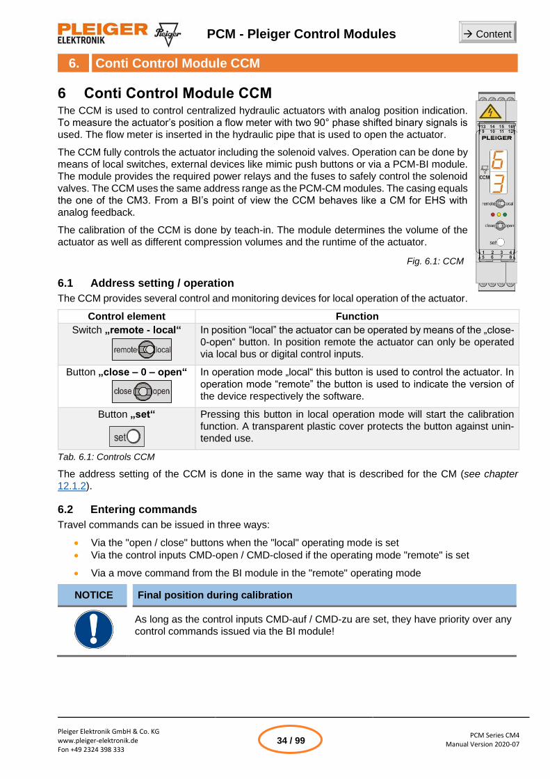
PCM - Pleiger Control Modules → Content
6. Conti Control Module CCM
Pleiger Elektronik GmbH & Co. KG www.pleiger-elektronik.de Fon +49 2324 398 333
34 / 99
PCM Series CM4 Manual Version 2020-07
6 Conti Control Module CCM The CCM is used to control centralized hydraulic actuators with analog position indication.
To measure the actuator’s position a flow meter with two 90° phase shifted binary signals is
used. The flow meter is inserted in the hydraulic pipe that is used to open the actuator.
The CCM fully controls the actuator including the solenoid valves. Operation can be done by
means of local switches, external devices like mimic push buttons or via a PCM-BI module.
The module provides the required power relays and the fuses to safely control the solenoid
valves. The CCM uses the same address range as the PCM-CM modules. The casing equals
the one of the CM3. From a BI’s point of view the CCM behaves like a CM for EHS with
analog feedback.
The calibration of the CCM is done by teach-in. The module determines the volume of the
actuator as well as different compression volumes and the runtime of the actuator.
6.1 Address setting / operation
The CCM provides several control and monitoring devices for local operation of the actuator.
Control element Function
Switch „remote - local“
In position “local” the actuator can be operated by means of the „close-
0-open“ button. In position remote the actuator can only be operated
via local bus or digital control inputs.
Button „close – 0 – open“
In operation mode „local“ this button is used to control the actuator. In
operation mode “remote” the button is used to indicate the version of
the device respectively the software.
Button „set“
Pressing this button in local operation mode will start the calibration
function. A transparent plastic cover protects the button against unin-
tended use.
Tab. 6.1: Controls CCM
The address setting of the CCM is done in the same way that is described for the CM (see chapter
12.1.2).
6.2 Entering commands
Travel commands can be issued in three ways:
• Via the "open / close" buttons when the "local" operating mode is set
• Via the control inputs CMD-open / CMD-closed if the operating mode "remote" is set
• Via a move command from the BI module in the "remote" operating mode
NOTICE Final position during calibration
As long as the control inputs CMD-auf / CMD-zu are set, they have priority over any
control commands issued via the BI module!
Fig. 6.1: CCM

PCM - Pleiger Control Modules → Content
6. Conti Control Module CCM
Pleiger Elektronik GmbH & Co. KG www.pleiger-elektronik.de Fon +49 2324 398 333
35 / 99
PCM Series CM4 Manual Version 2020-07
6.3 Output of analog position signal (actual position)
The CCM has a 4..20mA output that shows the current position.
• 4mA = closed
• 20mA = open
The current output is not isolated. The maximum burden resistor is 180 ohms. The maximum deviation
from the 7-segment display is ± 2 percentage points. This current output is intended for position indica-
tion via a display instrument and not for the connection to a higher-level control system.
6.3.1 Position measurement
A flow meter inserted in the hydraulic pipe that opens the actuator is used to determine the actual
position of the drive. Several compression volumes are considered to determine the position as exactly
as possible.
As an incremental measuring is used referencing is required from time to time. Each time the final
positions are reached, the actuator stops and the position is less than 3% or more than 97% the actual
position is set to 0% respectively 100%.
6.4 Behavior in the event of a power failure
If the 24 VDC supply fails, the current meter reading is permanently saved in the flash memory of the
CCM. When the voltage returns, the counter reading is restored. It is not possible to record counting
pulses when the power supply is switched off.
6.5 Display
6.5.1 Position indicator
Two 7-segment displays arranged one above the other serve to display the current position of the drive
and further status information.
The end positions are indicated with for „close“ and for „open“. All intermediate positions are indi-
cated with.. as a percentage opening.
If the decimal point of the least significant digit lights up, it means that the count value has been refer-
enced. A flashing of both decimal points every second indicates that the position has not yet been
referenced after the module has been switched on. If the position of the drive has changed while the
CCM was switched off, the position display is incorrect!
6.5.2 Start messages and self-test
Immediately after the program starts, the module shows the last "reset" cause on the 7-segment display.
The module then carries out a short self-test. If the self-test is not carried out successfully, the yellow
LED starts to flash.
6.5.3 Status LED
Three LEDs (red, yellow, green) indicate the operating status of the drive and the control
module.
LED red LED green Meaning
ON OFF Actuator closed in end position
ON flashes 1/s Actuator closed in end position, open command received
OFF flashes 1/s Actuator moves in the open direction, leave the end position close

PCM - Pleiger Control Modules → Content
6. Conti Control Module CCM
Pleiger Elektronik GmbH & Co. KG www.pleiger-elektronik.de Fon +49 2324 398 333
36 / 99
PCM Series CM4 Manual Version 2020-07
OFF ON Open actuator in end position
flashes 1/s ON Actuator open in end position, close command received
flashes 1/s OFF Actuator moves in the close direction, leave the end position open
flashes 2/s ON / OFF Close: target position not reached within runtime
ON / OFF flashes 2/s Open: target position not reached within runtime
Tab. 6.2: CCM LED red/green
The yellow LED is used to indicate the operating status of the control module.
LED yellow Meaning
ON 230 VAC supply voltage missing or fuse defective
OFF Supply voltage available, no (valid) data on the local bus
Flashing Supply voltage available and valid telegrams on the local data bus, but this CCM is
not addressed
Flickers Supply voltage available, communication with bus interface BI is running
Tab. 6.3: CCM LED yellow
6.6 Extended operation modes
Besides the default operation mode the CCM provides several extended modes. If the “set” button is
pressed for 3s while CCM is in “remote” mode the extended operation mode is shown. The upper digit always shows E. and the lower one a number. By means of the “open/close” switch the desired number
can be selected. Each Bit in this number enables a certain mode. The default value is E0.
extended operation mode “local override“,
the inputs for the mimic push buttons are always enabled. This mode is required if the mimic
inputs are used for some safety functions that must be independent from the local / remote
switch.
extended operation mode “flow meter in pipe used to close the actuator”.
This mode is required if the flow meter is inserted in the pipe that is used to close the actuator.
Attention: During calibration run the actuator first starts opening and remains in open position
at the end of the test.
extended operation mode “very slow actuators”
this mode is required if very slow actuators are used. In this case the timeout periods are ex-
tended:
- close timeout and open timeout from 4 to 10 minutes
- calibration timeout from 10 to 20 minutes
extended operation mode “counter inhibit on lamp test”
In this operation mode the lamp test input has an additional function. When lamp test is set the
counter is blocked and no command can be entered, neither manually nor via serial interface.
This operating mode is used when the central hydraulic unit is to be switched off for a long
time and the oil pressure on the meter decreases as a result.
The extended operation modes may also be combined. If for example you want to enable the “local
override” mode for “very slow actuators” you may add both numbers 1 and 4 and select mode .

PCM - Pleiger Control Modules → Content
6. Conti Control Module CCM
Pleiger Elektronik GmbH & Co. KG www.pleiger-elektronik.de Fon +49 2324 398 333
37 / 99
PCM Series CM4 Manual Version 2020-07
6.7 Calibration
After installation the CCM must be calibrated. During calibration the CCM calculates all parameters
concerning the actuator and the piping and stores these parameters in an internal non-volatile memory.
NOTICE Final position during calibration
During calibration, check that the actuator reaches both final positions!
The calibration run is started by pressing the SET button while the operation mode is set to “local“. The
calibration passes the following steps:
C Action End
1 actuator closes, valve b is on counter stopped
2 actuator stop, both valves off counter stopped and set to 0
3 actuator opens, valve a is on counter stopped and value > 500 incr.
4 actuator stop, both valves off counter stopped (counter value equals 100%
5 actuator closes, valve b is on counter stopped and counter value < 3%
6 actuator stop, both valves off counter stopped (counter = 0 )
7 actuator opens, valve a is on counter > 30%
8 actuator stop, both valves off counter stopped
9 actuator closes, valve b is on counter < 10%
a actuator stop, both valves off counter stopped
b actuator closes, valve b is on counter stopped
c actuator stop, both valves off counter stopped (counter = 0 )
Tab. 6.4: Steps of the CCM calibration run
The current step is indicated on the 7 segment display: ...
The run can be interrupted by changing the operating mode. The calibration run can be carried out
again at any time, provided the opening of the flap is permitted.
6.8 Lamp test
Terminal 3 of the local bus is used as a lamp test input. As soon as 24V is applied, the 3 LEDs of the
module light up, all segments and the decimal points of the 7-segment displays and in addition the two
message outputs LED open and LED closed are switched on.
6.9 Alarm output
After a successful self-test, the alarm output is initially closed. As soon as a fault occurs (see above),
the output is opened. The output is only closed again when all faults have been eliminated. Faults that
lead to the opening of the alarm contact are:
• 24 VDC or 230 VAC power failure
• Runtime exceeded while the drive is moving
• Internal failure

PCM - Pleiger Control Modules → Content
6. Conti Control Module CCM
Pleiger Elektronik GmbH & Co. KG www.pleiger-elektronik.de Fon +49 2324 398 333
38 / 99
PCM Series CM4 Manual Version 2020-07
6.10 Terminal assignment
CAUTION Supply of solenoid valves
Connecting the AC-supply: always plug in red connector last
Disconnecting the AC-supply: always pull red connector off first!
Fig. 6.2: Side view CCM
Tab. 6.5: Terminal assignment CCM
Fig. 6.3: Terminal CCM
13 FB-analog A Position signal (4..20mA), max. burden 150 Ohm
14 0 VDC / 230 VAC L1 A common terminal for solenoid valves
15 24 VDC / 230 VAC L2 zu A power output close, (coil „b“)
16 24 VDC / 230 VAC L2 auf A power output open, (coil „a“)
9 Count A E counter input A, A prior to B means counting up
10 Count B E counter input B, B prior to A means counting dow
11 0V A DC power supply for flow meter
12 24V A DC power supply for flow meter
1 LED-open A drive is open, to mimic diagram
2 LED-closed A drive is closed, to mimic diagram
3 CMD-open E command open, from mimic diagram
4 CMD-close E command close, from mimic diagram
5 0 VDC / 230 VAC L2 E solenoid valve supply voltage
6 24 VDC / 230 VAC L1 E solenoid valve supply voltage
7 Alarm
A contact opens in case of error, potential-free con-
tact 8 A

PCM - Pleiger Control Modules → Content
6. Conti Control Module CCM
Pleiger Elektronik GmbH & Co. KG www.pleiger-elektronik.de Fon +49 2324 398 333
39 / 99
PCM Series CM4 Manual Version 2020-07
CAUTION Damage to the device / malfunction of the actuators
ONLY place the 230 VAC supply voltages on the terminals provided. Otherwise the
modules may be damaged or destroyed.
6.11 Interface to flowmeter
Any flow meter connected to the CCM must comply with the following technical data.
Supply voltage 24 VDC
Current consumption max. 100mA, incl. counter, plus external load
Output signals 2 x rectangular signals 24V DC , 90° 20° phase shifted,
Pulse:Pause 1:1 10%
Min. Flankenabstand 80µs, up to 3kHz pulse frequency
Tab. 6.6: Technicle data flowmeter
6.12 Technical data
Technische Daten
Fuse DC self-resetting fuse, 500mA - 1100mA
Supply voltage solonid valves 230 VAC or 24 VDC
Fuse AC 2 x 1,25 AT Fuse (5x20mm), (max. 3,15AT)
Counting frequency max. 2,5kHz, min. Edge spacing 100µs
Analog position input 4..20mA = 0..100%, devitation 2%, max. burden resistance 180
Ohm
Mimic -open / -close solid state high side switches, max. load 150mA, short circuit proof
Terminal type screw terminals, max. 2,5mm²
Tab. 6.7: Technical Data CCM
* The current consumption of the feedback modules used in the EHS, e.g. OC3 and the currents output
via the mimic outputs must be added to the current consumption of the module.
B = 22,5 H = 105 T = 115
(mm)
IP20 0°Cxxx
-xxx
55°Cxxx
≤ 65mA
incl. counter,
+ext. loads*
24 VDC
+30%
-25%

PCM - Pleiger Control Modules → Content
7. Relay module RK16/8
Pleiger Elektronik GmbH & Co. KG www.pleiger-elektronik.de Fon +49 2324 398 333
40 / 99
PCM Series CM4 Manual Version 2020-07
7 Relay module RK16/8 The relay module provides 16 opto-decoupled digital inputs and 8 relay
outputs. The inputs are arranged in two groups with common 0V. A jumper
allows connecting both groups to the same 0V. The relay outputs are de-
signed as normally open contacts with one common terminal. The common
terminal is fused on-board. Standard fuse is 2AT, max. 10AT is allowed.
The fuse is monitored. A voltage drop of more than 100VAC will be indi-
cated and signalled. The relay contacts may switch up to 3A / 230V.
A short cable with two plugs serves to connect the RK 16/8
with each other.
Fig. 7.1: RK16/8
7.1 Address setting / operation
A button is used to set and display the module address. This function are only available in connection
with the BI module from software version 2.1. The address setting assumes that the BI is operated in
setup mode. A detailed description can be found in chapter 12.1.3.
In the normal operating mode of the BI module, the button is used to output the address of the RK
module. If you press the button for a longer time, the software version is displayed.
7.2 Counter function
To collect rapidly changing input values the RK provides a counter function for the input 1. Both raising
and falling edges of the input signal are counted and stored in an 8 bit counter value. If the counter
reaches 255 it will be reset on the next edge of the input signal.
Each pulse must last at least 15ms. The counter value must be read frequently to detect a counter
overrun reliably. With pulse duration of 15ms the counter must be read at least every 15ms*255 =
3825ms.
7.3 Operation mode: Digital inputs with off-delay
If required the operation mode of the RK inputs can be changed in such a way that even a short high
level at an input is indicated as high signal for 0,9s. Hereby it can be ensured that even very short events
are captured. The set-up is described in chapter 12.1.3.2.
7.4 Indication
The module is equipped with 24 LED for indication of the input and output state. An additional yellow
LED is used for status display.
• 16 green LED indicate the state of the digital inputs.
• 8 yellow LED indicate the state of the digital outputs.
The status LED indicates the data traffic on the local bus, a fuse fail and also assists the user during
setup of the module.
LED yellow Meaning
ON fuse fail, voltage drop on fuse > 100 VAC
OFF no fuse fail, no data on the local bus
Blinking no fuse fail, valid data on local bus but module is not addressed
Flickering no fuse fail, communication on local bus is running
Tab. 7.1: RK16/8 status LED yellow
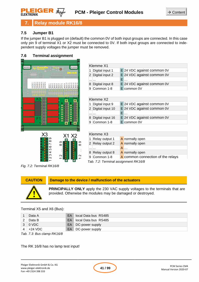
PCM - Pleiger Control Modules → Content
7. Relay module RK16/8
Pleiger Elektronik GmbH & Co. KG www.pleiger-elektronik.de Fon +49 2324 398 333
41 / 99
PCM Series CM4 Manual Version 2020-07
7.5 Jumper B1
If the jumper B1 is plugged on (default) the common 0V of both input groups are connected. In this case
only pin 9 of terminal X1 or X2 must be connected to 0V. If both input groups are connected to inde-
pendent supply voltages the jumper must be removed.
7.6 Terminal assignment
Tab. 7.2: Terminal assignment RK16/8
Fig. 7.2: Terminal RK16/8
CAUTION Damage to the device / malfunction of the actuators
PRINCIPALLY ONLY apply the 230 VAC supply voltages to the terminals that are
provided. Otherwise the modules may be damaged or destroyed.
Terminal X5 and X6 (Bus):
1 Data A EA local Data bus RS485
2 Data B EA local Data bus RS485
3 0 VDC EA DC-power supply
4 +24 VDC EA DC-power supply
Tab. 7.3: Bus clamp RK16/8
The RK 16/8 has no lamp test input!
Klemme X1
1 Digital input 1 E 24 VDC against common 0V
2 Digital input 2 E 24 VDC against common 0V
... ... E …
8 Digital input 8 E 24 VDC against common 0V
9 Common 1-8 E common 0V
Klemme X2
1 Digital input 9 E 24 VDC against common 0V
2 Digital input 10 E 24 VDC against common 0V
... ... E …
8 Digital input 16 E 24 VDC against common 0V
9 Common 1-8 E common 0V
Klemme X3
1 Relay output 1 A normally open
2 Relay output 2 A normally open
... ... A …
8 Relay output 8 A normally open
9 Common 1-8 A common connection of the relays

PCM - Pleiger Control Modules → Content
7. Relay module RK16/8
Pleiger Elektronik GmbH & Co. KG www.pleiger-elektronik.de Fon +49 2324 398 333
42 / 99
PCM Series CM4 Manual Version 2020-07
CAUTION Damage to the device / malfunction of the actuators
NEVER put the supply voltage on the local data bus.
Otherwise all connected modules can be damaged.
7.7 Technical Data
Technical Data
Fuse DC self-resetting fuse, 500mA – 1100mA
Terminal input screw terminals, max. 1,5mm²
Power supply 24 VDC
Threshold 6-12V, typ. 9V
Counter pulse length ≥ 15ms
Terminal outpt Screw terminals, max. 2,5mm²
Output voltage max. 230 VAC
Output current max. 2A per output
Fuse output default 2AT, max. 10AT
Tab. 7.4: Technical Data RK16/8
B = 102 H = 126 T = 30
(mm)
IP20 0°Cxxx
-xxx
55°Cxxx
≤ 100mA
24 VDC
+30%
-25%

PCM - Pleiger Control Modules → Content
8. Input/output module IO8/8/4
Pleiger Elektronik GmbH & Co. KG www.pleiger-elektronik.de Fon +49 2324 398 333
43 / 99
PCM Series CM4 Manual Version 2020-07
8 Input/output module IO8/8/4 The IO module is an assembly group for registering analog and digital signals and for the
output of digital signals.
All signal transmitters must be isolated, as this module does not provide internal potential
separation. Generally speaking, this is the case for temperature and pressure sensors or limit
switches, floating switches and dry relay contacts.
Insofar as this is not applicable, isolation amplifiers or isolating relays must be used
This also applies correspondingly to the digital outputs that are designed as short-circuit proof
semi-conductor relays, dispensing 24V supply voltage.
Fig. 8.1: IO8/8/4
8.1 Address setting / operation
Fig. 8.2: Address DIP-Switch
The module address is adjusted with the assistance of a
quadruple switch. The switch is to be found behind a trans-
parent cover flap.
The address range of the IO modules starts at 51 and fin-
ishes at 60.
The range beginning with setting 0101 is also mapped to the
addresses 51 to 56. In this case the state of the digital input
is hold for at least 0,9s. By this means even very short
events like pressing a push button can be detected securely
(Version B.6 and higher).
0 = OFF, 1 = ON
* state of digital inputs is hold for at least 0,9s
8.2 Displays
The module has a total of 20 LED at its disposal to display the input or output status
• 8 green LED indicate the status of the individual measured values.
LED green Eingangssignal Bedeutung
ON ≥ 3,8mA und ≤ 20,2mA valid measurement
OFF ≤ 0,2mA not used or wire broken
Blinking > 0,2mA und < 3,8mA below range
Flickering > 20,2mA above range or short circuit
Tab. 8.2: IO8/8/4 LED green
• 8 yellow LED indicate the status of the digital inputs.
• 4 red LED indicate the status of the digital outputs.
Furthermore, the LED are used to display any error status. In this connection the 4 lower and 4 upper
green LED flash alternately whilst the yellow LED indicate the error number from 1..8.
Module address
Switch
S1 S2 S3 S4
51 0 0 0 0
52 1 0 0 0
53 0 1 0 0
54 1 1 0 0
55 0 0 1 0
56 1 0 1 0
57 0 1 1 0
58 1 1 1 0
59 0 0 0 1
60 1 0 0 1
51* 0 1 0 1
52* 1 1 0 1
53* 0 0 1 1
54* 1 0 1 1
55* 0 1 1 1
56* 1 1 1 1 Tab. 8.1: Address setting IO8/8/4
addre
ss

PCM - Pleiger Control Modules → Content
8. Input/output module IO8/8/4
Pleiger Elektronik GmbH & Co. KG www.pleiger-elektronik.de Fon +49 2324 398 333
44 / 99
PCM Series CM4 Manual Version 2020-07
LED Nr. Error Comment
1 Address changed the module address was changed during operation
2-7 reserved
8 Module offline There is no data connection to the BI module
Tab. 8.3: IO8/8/4 LED gelb
Alteration to the module address initially brings about the output of the “address changed“ error mes-
sage. This error message also brings about the display of the module address on the fieldbus interface.
The new module address is not accepted until the module has been restarted.
8.2.1 Start messages and self-test
Directly after the start of the programme the module displays the last reset cause by illuminating one of
the yellow LED briefly. The module subsequently carries out a short self-test. In the event that the self-
test is not carried out successfully, the two lowest green LED will start to flash.
Normal status display commences once the self-test has been carried out successfully (see above).
8.2.2 Lamp test
Terminal no. 3 on the local bus is used as a lamp test input. As soon as 24V are applied the 8 green
and 8 yellow LED are illuminated. The red LEDs are not activated during the lamp test.

PCM - Pleiger Control Modules → Content
8. Input/output module IO8/8/4
Pleiger Elektronik GmbH & Co. KG www.pleiger-elektronik.de Fon +49 2324 398 333
45 / 99
PCM Series CM4 Manual Version 2020-07
8.3 Terminal assignment
Fig. 8.3: Side view IO8/8/4
Tab. 8.4: Terminal assigment IO8/8/4
Fig. 8.4: Terminal IO8/8/4
CAUTION Damage to the device / malfunction of the actuators
PRINCIPALLY ONLY apply the 230 VAC supply voltages to the terminals that are
provided. Otherwise the modules may be damaged or destroyed.
17 Digital input 4 E 24 VDC to 0V of supply voltage
18 Digital input 3 E 24 VDC to 0V of supply voltage
19 Digital input 2 E 24 VDC to 0V of supply voltage
20 Digital input 1 E 24 VDC to 0V of supply voltage
13 Analog input 8 E 4 .. 20mA, to 0 VDC
14 Analog input 7 E 4 .. 20mA, to 0 VDC
15 Analog input 6 E 4 .. 20mA, to 0 VDC
16 Analog input 5 E 4 .. 20mA, to 0 VDC
9 Analog input 4 E 4 .. 20mA, to 0 VDC
10 Analog input 3 E 4 .. 20mA, to 0 VDC
11 Analog input 2 E 4 .. 20mA, to 0 VDC
12 Analog input 1 E 4 .. 20mA, to 0 VDC
1 Digital input 5 E 24 VDC to 0V of supply voltage
2 Digital input 6 E 24 VDC to 0V of supply voltage
3 Digital input 7 E 24 VDC to 0V of supply voltage
4 Digital input 8 E 24 VDC to 0V of supply voltage
5 Digital output 1 A 24 VDC to 0V of supply voltage
6 Digital output 2 A 24 VDC to 0V of supply voltage
7 Digital output 3 A 24 VDC to 0V of supply voltage
8 Digital output 4 A 24 VDC to 0V of supply voltage
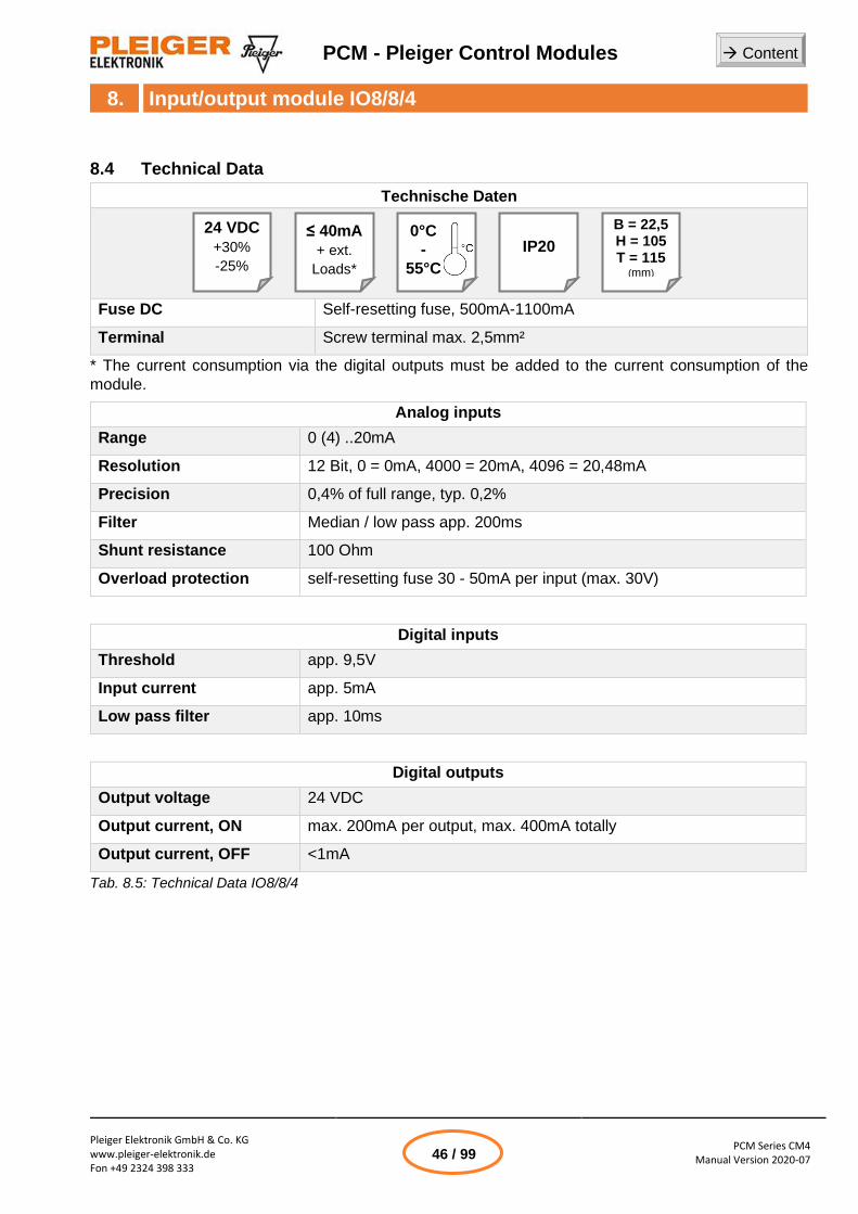
PCM - Pleiger Control Modules → Content
8. Input/output module IO8/8/4
Pleiger Elektronik GmbH & Co. KG www.pleiger-elektronik.de Fon +49 2324 398 333
46 / 99
PCM Series CM4 Manual Version 2020-07
8.4 Technical Data
Technische Daten
Fuse DC Self-resetting fuse, 500mA-1100mA
Terminal Screw terminal max. 2,5mm²
* The current consumption via the digital outputs must be added to the current consumption of the
module.
Analog inputs
Range 0 (4) ..20mA
Resolution 12 Bit, 0 = 0mA, 4000 = 20mA, 4096 = 20,48mA
Precision 0,4% of full range, typ. 0,2%
Filter Median / low pass app. 200ms
Shunt resistance 100 Ohm
Overload protection self-resetting fuse 30 - 50mA per input (max. 30V)
Digital inputs
Threshold app. 9,5V
Input current app. 5mA
Low pass filter app. 10ms
Digital outputs
Output voltage 24 VDC
Output current, ON max. 200mA per output, max. 400mA totally
Output current, OFF <1mA
Tab. 8.5: Technical Data IO8/8/4
B = 22,5 H = 105 T = 115
(mm)
IP20 0°Cxxx
-xxx
55°Cxxx
≤ 40mA
+ ext.
Loads*
24 VDC
+30%
-25%

PCM - Pleiger Control Modules → Content
9. Input-/Output module TII
Pleiger Elektronik GmbH & Co. KG www.pleiger-elektronik.de Fon +49 2324 398 333
47 / 99
PCM Series CM4 Manual Version 2020-07
9 Input-/Output module TII The TII module is a module for the acquisition and output of analog signals.
It has 2 analog outputs (4… 20mA) and 8 analog inputs, including 2 current inputs (4…
20mA) and 6 inputs for PT 100 temperature sensors.
All analog inputs and outputs are isolated from the supply voltage.
These signal connections have the same reference potential among themselves, separate
TII modules must be used for a potential separation between different signal connections.
Fig. 9.1: TII
9.1 Address setting / operation
Fig. 9.2: Address DIP-switch
The module address is adjusted with the assis-
tance of a quadruple switch. The switch is to be found be-
hind a transparent cover flap.
The address range of the IO modules starts at 51 and fin-
ishes at 60.
The range from setting 0101 is in turn mapped to addresses
51 to 56.
0 = OFF, 1 = ON
* Additional function currently not used for TII, reserve for later
functional expansion
Tab. 9.1: Address setting TII
9.2 Displays
The TII provides 11 LED to indicate the input or output state and the operation state.
• • 6 green LEDs indicate the status of the individual temperature measurements.
LED green Input signal Meaning
ON ca. -10°C…+195°C valid measurement
OFF > ca. 200 °C not connected or range overflow
Flickering < ca. -15°C range underflow or short circuit
Tab. 9.2: TII LED green
Module address
Switch
S1 S2 S3 S4
51 0 0 0 0
52 1 0 0 0
53 0 1 0 0
54 1 1 0 0
55 0 0 1 0
56 1 0 1 0
57 0 1 1 0
58 1 1 1 0
59 0 0 0 1
60 1 0 0 1
51* 0 1 0 1
52* 1 1 0 1
53* 0 0 1 1
54* 1 0 1 1
55* 0 1 1 1
56* 1 1 1 1
addre
ss

PCM - Pleiger Control Modules → Content
9. Input-/Output module TII
Pleiger Elektronik GmbH & Co. KG www.pleiger-elektronik.de Fon +49 2324 398 333
48 / 99
PCM Series CM4 Manual Version 2020-07
• 2 yellow LED indicate the state of the analog inputs.
LED yellow Input signal Meaning
ON ≥ 3,8mA und ≤ 20,2mA valid measurement
OFF ≤ 0,2mA not connected, wire break or short circuit
Blinking > 0,2mA und < 3,8mA range underflow, still valid
Flickering > 20,2mA range overflow, still valid
Flickering
very fast
< ca. -0,1mA oder
> ca. 20,48mA
invalid measurement
Tab. 9.3: TII LED yellow
• 2 red LED indicate the state of the analog current output.
LED red Meaning Output signal
ON valid current output 0,08mA bis 20,48mA
OFF output value is ZERO unter 0,2mA
Flickering burden resistance to high or wire broken max. 20,48mA
Tab. 9.4: TII LED red
• 1 yellow LED indicates the module status.
Status-LED Error Meaning
starts blinking
during operation
address changed the address of the module has been changed while TII is
running
blinking directly
after start
self-test error the self-test during start-up failed.
on permanently None normal operation
Tab. 9.5: TII Status-LED yellow
9.2.1 Self-test and start-up indications
Immediately after the program starts, the cause of the restart of the processor is displayed:
LED green Meaning
LED 1 flashes once power-on reset
LED 2 flashes once external reset
LED 3 flashes once brown-out reset
LED 1
&
LED 3
both flashes once power-on reset and brown-out reset may occur simulta-
neously. In this case both green LEDs 1 and 3 flash
LED 4 flashes once watchdog reset
LED 5 flashes once JTAG reset
Fig. 9.3: TII start-up indication and self-test
The module then carries out a short self-test. If the self-test is not successful, the STATUS LED starts
to flash.
After a successful self-test, the data for the calibration of the analog values are checked. If the values
are invalid, the respective LED of the uncalibrated channel lights up briefly.
Between the test steps, all LEDs light up briefly once. After a successful self-test, the normal status
display begins, as described above.
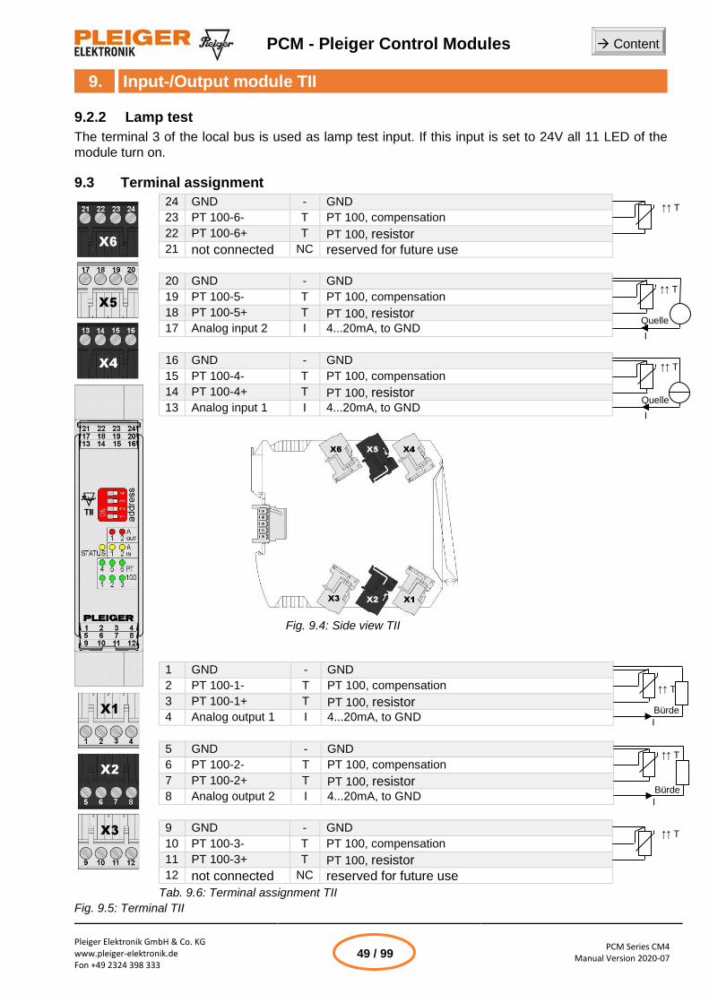
PCM - Pleiger Control Modules → Content
9. Input-/Output module TII
Pleiger Elektronik GmbH & Co. KG www.pleiger-elektronik.de Fon +49 2324 398 333
49 / 99
PCM Series CM4 Manual Version 2020-07
9.2.2 Lamp test
The terminal 3 of the local bus is used as lamp test input. If this input is set to 24V all 11 LED of the
module turn on.
9.3 Terminal assignment
24 GND - GND
23 PT 100-6- T PT 100, compensation
22 PT 100-6+ T PT 100, resistor 21 not connected NC reserved for future use
20 GND - GND
19 PT 100-5- T PT 100, compensation
18 PT 100-5+ T PT 100, resistor 17 Analog input 2 I 4...20mA, to GND
16 GND - GND
15 PT 100-4- T PT 100, compensation
14 PT 100-4+ T PT 100, resistor 13 Analog input 1 I 4...20mA, to GND
Fig. 9.4: Side view TII
1 GND - GND
2 PT 100-1- T PT 100, compensation
3 PT 100-1+ T PT 100, resistor 4 Analog output 1 I 4...20mA, to GND
5 GND - GND
6 PT 100-2- T PT 100, compensation
7 PT 100-2+ T PT 100, resistor 8 Analog output 2 I 4...20mA, to GND
9 GND - GND
10 PT 100-3- T PT 100, compensation
11 PT 100-3+ T PT 100, resistor 12 not connected NC reserved for future use
Tab. 9.6: Terminal assignment TII
Fig. 9.5: Terminal TII
↑↑ T
↑↑ T
↑↑ T
↑↑ T
↑↑ T
↑↑ T
I
Quelle
I
Quelle
Bürde
I
Bürde
I
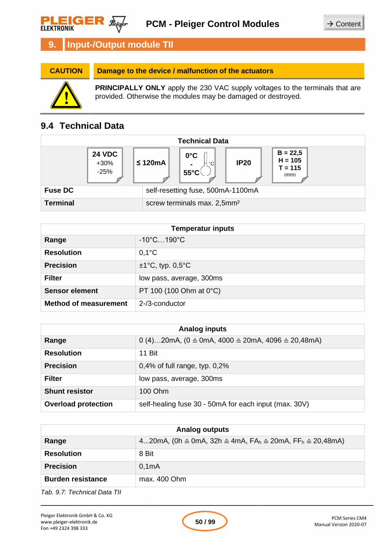
PCM - Pleiger Control Modules → Content
9. Input-/Output module TII
Pleiger Elektronik GmbH & Co. KG www.pleiger-elektronik.de Fon +49 2324 398 333
50 / 99
PCM Series CM4 Manual Version 2020-07
CAUTION Damage to the device / malfunction of the actuators
PRINCIPALLY ONLY apply the 230 VAC supply voltages to the terminals that are
provided. Otherwise the modules may be damaged or destroyed.
9.4 Technical Data
Technical Data
Fuse DC self-resetting fuse, 500mA-1100mA
Terminal screw terminals max. 2,5mm²
Temperatur inputs
Range -10°C…190°C
Resolution 0,1°C
Precision ±1°C, typ. 0,5°C
Filter low pass, average, 300ms
Sensor element PT 100 (100 Ohm at 0°C)
Method of measurement 2-/3-conductor
Analog inputs
Range 0 (4)…20mA, (0 ≙ 0mA, 4000 ≙ 20mA, 4096 ≙ 20,48mA)
Resolution 11 Bit
Precision 0,4% of full range, typ. 0,2%
Filter low pass, average, 300ms
Shunt resistor 100 Ohm
Overload protection self-healing fuse 30 - 50mA for each input (max. 30V)
Analog outputs
Range 4...20mA, (0h ≙ 0mA, 32h ≙ 4mA, FAh ≙ 20mA, FFh ≙ 20,48mA)
Resolution 8 Bit
Precision 0,1mA
Burden resistance max. 400 Ohm
Tab. 9.7: Technical Data TII
B = 22,5 H = 105 T = 115
(mm)
IP20 0°Cxxx
-xxx
55°Cxxx
≤ 120mA
24 VDC
+30%
-25%

PCM - Pleiger Control Modules → Content
10. Digital input module DI16
Pleiger Elektronik GmbH & Co. KG www.pleiger-elektronik.de Fon +49 2324 398 333
51 / 99
PCM Series CM4 Manual Version 2020-07
10 Digital input module DI16 The DI16 module is a module for the acquisition of 16 digital signals. All inputs are isolated
from the supply voltage via optocouplers.
8 inputs each are combined in a group with a common connection. The common connection
can be connected to 0V or + 24V of the signal source. For each input group it can be deter-
mined whether a 24V or a 0V signal should switch the input.
10.1 Address setting / operation
A button is used to set and display the module address. These functions are only available in
connection with the BI module from software version 2.A. The address setting requires that
the BI is operated in setup mode. A detailed description can be found in chapter 12.1.4.
In the normal operating mode of the BI module, the button is used to output the address of
the DI16 module. If the button is pressed for a longer time, the software version is displayed.
Fig. 10.1: DI16
10.2 Counter function
In order to be able to capture rapidly changing input variables, the DI16 also has a counter function for
input 1. Both edges of the input signal are always counted and stored in an 8-bit counter value. The
count value is incremented with each edge. When the count value reaches 255, the counter is reset
with the next counting pulse. In case of power failure the counter is cleared.
10.3 Displays
The module provides 17 LED to indicate the input state and the operation state.
• 1 yellow LED indicates the module status.
Status-LED Error Meaning
starts blinking
during operation
address changed the address of the module has been changed
while TII is running
blinking directly
after start of DI16
Self-test error the self-test during start-up failed.
on permanently None normal operation
Tab. 10.1: DI16 status-LED yellow
• 8 green and 8 red LED are indicating the state of the digital inputs.
10.3.1 Lamp test
The terminal 3 of the local bus is used as lamp test input. If this input is set to 24V all 17 LED of the
module turn on.

PCM - Pleiger Control Modules → Content
10. Digital input module DI16
Pleiger Elektronik GmbH & Co. KG www.pleiger-elektronik.de Fon +49 2324 398 333
52 / 99
PCM Series CM4 Manual Version 2020-07
10.4 Terminal assignment
Fig. 10.2: Side view DI16
Tab. 10.2: Terminal assignment DI16
Fig. 10.3: Terminal DI16
CAUTION Damage to the device / malfunction of the actuators
PRINCIPALLY ONLY apply the 230 VAC supply voltages to the terminals that are
provided. Otherwise the modules may be damaged or destroyed.
17 Digital input 13 E 24 VDC to V2- (0V to V2+)
18 Digital input 14 E 24 VDC to V2- (0V to V2+)
19 Digital input 15 E 24 VDC to V2- (0V to V2+)
20 Digital input 16 E 24 VDC to V2- (0V to V2+)
13 Digital input 9 E 24 VDC to V2- (0V to V2+)
14 Digital input 10 E 24 VDC to V2- (0V to V2+)
15 Digital input 11 E 24 VDC to V2- (0V to V2+)
16 Digital input 12 E 24 VDC to V2- (0V to V2+)
1 24 VDC (X1.2 = open) E V1+ digital inputs 1-8
2 0 VDC (X1.1 = open) E V1- digital inputs 1-8
3 24 VDC (X1.4 = open) E V2+ digital inputs 9-16
4 0 VDC (X1.3 = open) E V2- digital inputs 9-16
The supply voltage or reference potential must be selected between 24V or 0V
(for each group DI1-8 and DI9-16 separately)!
5 Digital input 1 E 24 VDC to V1- (0V to V1+)
6 Digital input 2 E 24 VDC to V1- (0V to V1+)
7 Digital input 3 E 24 VDC to V1- (0V to V1+)
8 Digital input 4 E 24 VDC to V1- (0V to V1+)
9 Digital input 5 E 24 VDC to V1- (0V to V1+)
10 Digital input 6 E 24 VDC to V1- (0V to V1+)
11 Digital input 7 E 24 VDC to V1- (0V to V1+)
12 Digital input 8 E 24 VDC to V1- (0V to V1+)

PCM - Pleiger Control Modules → Content
10. Digital input module DI16
Pleiger Elektronik GmbH & Co. KG www.pleiger-elektronik.de Fon +49 2324 398 333
53 / 99
PCM Series CM4 Manual Version 2020-07
10.5 Technical Data
Technical Data
Fuse DC self-resetting fuse, 500mA-1100mA
Terminal screw terminals max. 2,5mm²
* The current consumption via the digital outputs must be added to the current consumption of the
module.
Digitaleingänge
Signal threshold approx.9.5V
Input current approx. 5mA
Low pass filter approx. 10ms
counter pulse length ≥ 15ms
Tab. 10.3: Technical Data DI16
B = 22,5 H = 105 T = 115
(mm)
IP20 -25°Cxxx
-xxx
55°Cxxx
≤ 70mA
24 VDC
+30%
-25%
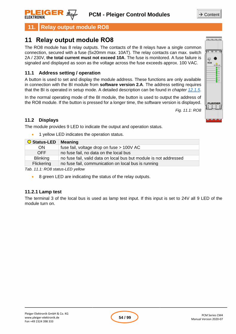
PCM - Pleiger Control Modules → Content
11. Relay output module RO8
Pleiger Elektronik GmbH & Co. KG www.pleiger-elektronik.de Fon +49 2324 398 333
54 / 99
PCM Series CM4 Manual Version 2020-07
11 Relay output module RO8 The RO8 module has 8 relay outputs. The contacts of the 8 relays have a single common
connection, secured with a fuse (5x20mm max. 10AT). The relay contacts can max. switch
2A / 230V, the total current must not exceed 10A. The fuse is monitored. A fuse failure is
signaled and displayed as soon as the voltage across the fuse exceeds approx. 100 VAC.
11.1 Address setting / operation
A button is used to set and display the module address. These functions are only available
in connection with the BI module from software version 2.A. The address setting requires
that the BI is operated in setup mode. A detailed description can be found in chapter 12.1.5.
In the normal operating mode of the BI module, the button is used to output the address of
the RO8 module. If the button is pressed for a longer time, the software version is displayed.
Fig. 11.1: RO8
11.2 Displays
The module provides 9 LED to indicate the output and operation status.
• 1 yellow LED indicates the operation status.
Status-LED Meaning
ON fuse fail, voltage drop on fuse > 100V AC
OFF no fuse fail, no data on the local bus
Blinking no fuse fail, valid data on local bus but module is not addressed
Flickering no fuse fail, communication on local bus is running
Tab. 11.1: RO8 status-LED yellow
• 8 green LED are indicating the status of the relay outputs.
11.2.1 Lamp test
The terminal 3 of the local bus is used as lamp test input. If this input is set to 24V all 9 LED of the
module turn on.
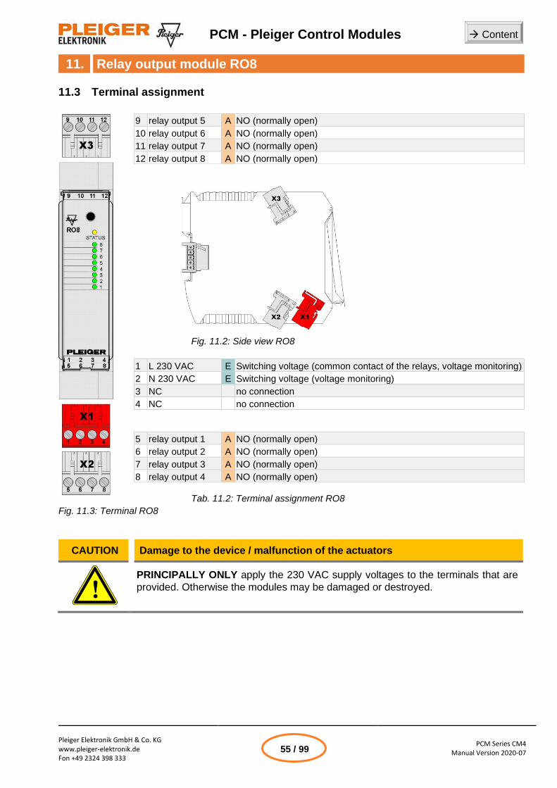
PCM - Pleiger Control Modules → Content
11. Relay output module RO8
Pleiger Elektronik GmbH & Co. KG www.pleiger-elektronik.de Fon +49 2324 398 333
55 / 99
PCM Series CM4 Manual Version 2020-07
11.3 Terminal assignment
Fig. 11.2: Side view RO8
Tab. 11.2: Terminal assignment RO8
Fig. 11.3: Terminal RO8
CAUTION Damage to the device / malfunction of the actuators
PRINCIPALLY ONLY apply the 230 VAC supply voltages to the terminals that are
provided. Otherwise the modules may be damaged or destroyed.
9 relay output 5 A NO (normally open)
10 relay output 6 A NO (normally open)
11 relay output 7 A NO (normally open)
12 relay output 8 A NO (normally open)
1 L 230 VAC E Switching voltage (common contact of the relays, voltage monitoring)
2 N 230 VAC E Switching voltage (voltage monitoring)
3 NC no connection
4 NC no connection
5 relay output 1 A NO (normally open)
6 relay output 2 A NO (normally open)
7 relay output 3 A NO (normally open)
8 relay output 4 A NO (normally open)

PCM - Pleiger Control Modules → Content
11. Relay output module RO8
Pleiger Elektronik GmbH & Co. KG www.pleiger-elektronik.de Fon +49 2324 398 333
56 / 99
PCM Series CM4 Manual Version 2020-07
11.4 Technical Data
Technical Data
Fuse self-resetting fuse, 500mA - 1100mA
Terminals screw terminals max. 2,5mm²
Switching voltage max. 230 VAC
Switching current max. 2A per contact
Output fuse standard 2AT, max. 10AT
Tab. 11.3: Technical Data RO8
B = 22,5 H = 105 T = 115
(mm)
IP20 -25°Cxxx
-xxx
55°Cxxx
≤ 120mA
24 VDC
+30%
-25%

PCM - Pleiger Control Modules → Content
12. Fieldbus interface BI from V2.7
Pleiger Elektronik GmbH & Co. KG www.pleiger-elektronik.de Fon +49 2324 398 333
57 / 99
PCM Series CM4 Manual Version 2020-07
12 Fieldbus interface BI from V2.7 From software version V2.7, the BI has some additional functions for safe and convenient
function in connection with CM4 modules and the parameterization tool PST.
• BI turns to passive mode if a PST wants to access the local bus
• BI provides a non-volatile memory to store the parameter sets all CM4
• BI performs an automatic parameter matching between CM4 and BI
• BI provides an extended Modbus interface to transfer parameters and software ver-
sion numbers
The fieldbus interface serves to connect the control and IO modules to a superimposed con-
trol system via a fieldbus. Furthermore, the module provides two control inputs and a collec-
tive alarm output.
Two 7-segment displays and two push-buttons serve to parameterise the module and display
system status.
Two fieldbus protocol variations are available: Fig. 12.1: BI
• Modbus RTU, Slave
• Profibus DP V0, Slave
The choice of the fieldbus protocol is carried out via the parameterisation functions on the module. The
fieldbus lines are connected via terminal screws. Bus termination in accordance with the Profibus stand-
ard can be activated via a miniature switch if required.
NOTE Profibus interface
The Profibus Interface is only available on BI modules with Art.No. 9341100200.
Those BI only provide Modbus RTU. If Profibus is selected anyhow an error message
is indicated.
12.1 Operation
Parameterisation of the module is carried out with the assistance of the
“set“ and “Prgm“ push-buttons. The push-buttons are only accessible if the
transparent lid on the module is opened. Display of the chosen parameters
is by means of two 7-segment displays.
12.1.1 Parameterisation of the fieldbus
Parameterisation of the fieldbus settings is only possible if the “Prgm“ push-button is depressed for at
least 3s when switching on the module. After this all parameters must be entered in succession. The
“Set“ key is always used to set the value and the “Prgm“ key to accept the value. All parameters are
saved in a non-volatile memory.
lower digit
higher digit

PCM - Pleiger Control Modules → Content
12. Fieldbus interface BI from V2.7
Pleiger Elektronik GmbH & Co. KG www.pleiger-elektronik.de Fon +49 2324 398 333
58 / 99
PCM Series CM4 Manual Version 2020-07
Parameter sequence
Step Meaning Range of values Display (example)
1 Address, least significant digit x 0h … x Fh, - any, firm …
2 Address, most significant digit 0 xh … 6 xh, - any, firm …
3 Selection baud rate / protocol 4k8 / 9k6/ 19k2 / 38k4 / 56k /
57k6 / 76k8 / 115k2 / Profibus DP
Modbus only
4 Selection of parity none / odd / even ...
...
Tab. 12.1: Parameterisation fieldbus
If the Profibus is chosen during step 3, step 4 is not applicable. Automatic baud rate setting is generally
used for the Profibus protocol.
When the last parameter is entered the module changes to normal operation.
12.1.2 Setting the address of CM (CM3, CM4, CM4-D, CCM) modules
12.1.2.1 Setting the module address
The address of the CM control modules is adjusted with the assistance of the CM control elements.
Those modules do not provide separate address switches. Operation mode changeover on the CM
module brings about the indication of the current module address on the fieldbus interface for the dura-
tion of approx. 2 seconds.
Since the address setting must be protected against unintentional changes, it is necessary to
put the system in addressing mode. For this purpose, both buttons "Prgm" and "Set" are
pressed simultaneously on the fieldbus coupler. This operating mode is indicated by the flashing
display. To exit this operating mode, both buttons must be pressed again at the same time.
Now the CM module to be programmed is switched to the "remote" operating mode. By pressing
the command key in any direction (close / open) the lowest free address on the local bus is now
displayed. A free address is an address to which no CM module responds. Now the two pro-
gramming functions "Delete" and "Apply" are available.
New modules are programmed in turn from left to right. Once programming has been completed the
fieldbus interface must be set to normal operation mode. For this both buttons are again pressed sim-
ultaneously.
NOTICE Module address
The module address determines which register / data word is used by this actuator
in the data model of the fieldbus connection. If the address is not allocated as ar-
ranged, the wrong valve will be activated. If possible, addressing should be carried
out in such a way that the address complies with the slot, i.e. that the 7th module, for
example, is given address no. 7.
12.1.2.2 Deleting the module address
If the command key is pushed in the direction of “open“ and the operation mode is then switched to local
while the command key is depressed, the module address is erased. The module is then no longer
visible for the fieldbus interface.
PCM - Pleiger Control Modules → Content
12. Fieldbus interface BI from V2.7
Pleiger Elektronik GmbH & Co. KG www.pleiger-elektronik.de Fon +49 2324 398 333
59 / 99
PCM Series CM4 Manual Version 2020-07
12.1.2.3 Accepting the lowest available address
If the command key is pushed in the direction of “close“ and the operation mode is then switched to
local while the command key is depressed, the module address is set to the lowest available address.
This new address can be displayed again by changing the operation mode.
12.1.3 Setting the address and operation mode of the RK16/8
The address of the RK16/8 modules is adjusted by means of the push button near the status LED. If
the button is pressed the module’s address is displayed at the BI. If the button is pressed for more than
3s the module’s software version is displayed instead of the address.
As the address setting needs to be protected against unintentional alteration, it is necessary to
put the system in addressing mode. Addressing mode is set by pressing the “Prgm” and “Set”
keys on the BI simultaneously. This operation mode is shown as on the BI display. To leave
this mode just press both push buttons once more.
Now the push button of the appropriate RK 16/8 must be pressed for some seconds. The status
LED first lights brightly and the turns off. The BI module now shows the lowest unused address
for an RK module in the range 61..80. As soon as the LED turns on again the button may be
released. The RK 16/8 is now programmed.
New modules are programmed in turn from left to right. Once programming has been completed the
fieldbus interface must be set to normal operation mode. For this both buttons are again pressed sim-
ultaneously.
NOTICE Module address
The module address determines which register / data word is used by this actuator
in the data model of the fieldbus connection.
12.1.3.1 Deleting the module address
To erase the module address the button must be pressed again. As soon as the LED turns off the button
must be released. The module address is erased now and the module becomes invisible for the BI.
12.1.3.2 Setting the operation mode
If the button is kept pressed after the LED turns on again for at least 2,5s the LED starts blinking. This
indicates the activation of the extended operation mode. In this case the state of each digital input is
hold for at least 0,9s. By this means even very short events can be detected securely. The version
changes from .x to .x if this operation mode is turned on (Version D.4 and higher).

PCM - Pleiger Control Modules → Content
12. Fieldbus interface BI from V2.7
Pleiger Elektronik GmbH & Co. KG www.pleiger-elektronik.de Fon +49 2324 398 333
60 / 99
PCM Series CM4 Manual Version 2020-07
12.1.4 Setting the address of the DI16
The address of the DI16 modules is adjusted by means of the push button near the status LED. If the
button is pressed the module’s address is displayed at the BI. If the button is pressed for more than 3s
the module’s software version is displayed instead of the address.
As the address setting needs to be protected against unintentional alteration, it is necessary to
put the system in addressing mode. Addressing mode is set by pressing the “Prgm” and “Set”
keys on the BI simultaneously. This operation mode is shown as on the BI display. To leave
this mode just press both push buttons once more.
Now the push button of the appropriate DI16 must be pressed for some seconds. The status
LED first lights brightly and the turns off. The BI module now shows the lowest unused address
for an DI16 module in the range 61..80. As soon as the LED turns on again the button may be
released. The DI16 is now programmed.
New modules are programmed in turn from left to right. Once programming has been completed the
fieldbus interface must be set to normal operation mode. For this both buttons are again pressed sim-
ultaneously.
NOTICE Module address
The module address determines which register / data word is used by this actuator
in the data model of the fieldbus connection.
12.1.4.1 Deleting the module address
To erase the module address the button must be pressed again. As soon as the LED turns off the button
must be released. The module address is erased now and the module becomes invisible for the BI.
12.1.5 Setting the address and operation mode of the RO8
The address of the RO8 modules is adjusted by means of the push button near the status LED. If the
button is pressed the module’s address is displayed at the BI. If the button is pressed for more than 3s
the module’s software version is displayed instead of the address.
As the address setting needs to be protected against unintentional alteration, it is necessary to
put the system in addressing mode. Addressing mode is set by pressing the “Prgm” and “Set”
keys on the BI simultaneously. This operation mode is shown as on the BI display. To leave
this mode just press both push buttons once more.
Now the push button of the appropriate RO8 must be pressed for some seconds. The status
LED first lights brightly and the turns off. The BI module now shows the lowest unused address
for an RO8 module in the range 81..100. As soon as the LED turns on again the button may be
released. The RO8 is now programmed.
New modules are programmed in turn from left to right. Once programming has been completed the
fieldbus interface must be set to normal operation mode. For this both buttons are again pressed sim-
ultaneously.

PCM - Pleiger Control Modules → Content
12. Fieldbus interface BI from V2.7
Pleiger Elektronik GmbH & Co. KG www.pleiger-elektronik.de Fon +49 2324 398 333
61 / 99
PCM Series CM4 Manual Version 2020-07
NOTICE Module address
The module address determines which register / data word is used by this actuator
in the data model of the fieldbus connection.
12.1.5.1 Deleting the module address
To erase the module address the button must be pressed again. As soon as the LED turns off the button
must be released. The module address is erased now and the module becomes invisible for the BI.
12.1.6 Skipping addresses
From software version V1.6 of the bus coupler, a function is also available that allows individual ad-
dresses to be skipped. First the addressing is carried out until the lowest free address is displayed. The
next free address can now be selected by pressing the "Set" button on the bus coupler once. Pressing
again selects the free address that follows, etc. Pressing the "Prgm" key displays the previous free
address again. The setting chosen in this way, i.e. the number of address gaps remains until the ad-
dressing mode is exited.
12.1.7 Parameter matching BI / CM4
If a BI and the connected CM4 start running after power-up the BI reads the parameter sets of all CM4
and compares them with their local copy. Make sure that the CM4 addresses are set properly. If there
are any deviations the following cases may occur:
State BI-module State CM4-module Reaction Action requi-
red
default parameter
set
valid parameter set BI copies parameter from CM4,
CM4 uses internal parameter
NO
valid parameter set default parameter set BI sends parameter to CM4, CM4
uses new parameter
NO
valid parameter
(≠ CM4)
valid parameter
(≠ BI)
BI indicates and address of
CM4 alternating, CM4 uses inter-
nal parameter set
YES
Tab. 12.2: Cases with parameter deviations BI / CM4
In the latest case a parameter conflict occurs. This may happen if both modules BI and CM4 have been
used in a different application before. This conflict is indicated by the BI display. There the characters
and a two-digit number in the range 01…50 the CM4 address are shown rotationally. If several of
such conflicts are detected only the lowest address is shown.
CAUTION Parameter conflict
If a parameter conflict occurs, it must be resolved by the user. To do this, the operator
must decide which parameter set is invalid.
PCM - Pleiger Control Modules → Content
12. Fieldbus interface BI from V2.7
Pleiger Elektronik GmbH & Co. KG www.pleiger-elektronik.de Fon +49 2324 398 333
62 / 99
PCM Series CM4 Manual Version 2020-07
Usually this conflict will happen if one module has been replaced, either a BI or a CM4, by a module
that has been used in other applications before. In this case the parameter set of the replaced module
has to be erased by the user. This is done in the following way:
BI When starting the BI, hold down the ”Prgm” button and then press the ”Prgm” button until the BI
is back in normal operating mode and displays . The BI module replaces all parameter sets with
the default values and at the next system start the parameter sets of all CM4 are copied into the
BI.
CM4 Turn the BI to setup mode by pressing the ”Prgm” and ”Set” button of the BI simultaneously until
the blinking is indicated. Now set the address of the replaced CM4 in the usual way. All param-
eters of the CM4 are reset now and subsequently restored by the copy stored in the BI when the
system is restarted the next time.
NOTICE Parametrierung CM4 / BI
If in doubt, the PCM-PST must be used to parameterize the affected CM4 and, in
parallel, the BI. The required parameters are specified in the system circuit diagrams.
12.1.8 Display functions
Various system data can be displayed for diagnosis purposes in connection with the “Set” and “Prgm”
keys of the fieldbus interface or the operation mode switches of the CM.
Display of a Parameter Conflict
From version V2.7 and in conjunction with CM4, a possible parameter error is displayed. and the address of the affected CM4 appear alternately. If there are several errors, the
last error found is always displayed.
Indicate writing to EEPROM of the BI
. From version V2.7, it is shown when the BI writes parameter sets to the EEPROM or deletes
them. The display .. may only appear if a saving process occurs. A permanent or recurring
ad .. therefore represents a module error .
Display of new command
. If the BI receives a command for a certain CM via Modbus interface, the address of the CM
is indicated. Both decimal points are turned on if the command is passed to the CM. The
indication is turned off if the CM starts executing the command. .
Display of the Address of a CM module
Upon changing the operation mode (local – remote) of a CM its address is displayed for 2
seconds via the 7 segment display of the BI ( = address 12). This function helps to check
the correct address setting.
Display of the CM software version
. If the operation mode of the CM is remote and the open command button is pressed the
version number of the CM is shown on the BI display (.= Version 2.5). If the extended
operation mode of a CM is set the extended operation mode is shown on the display if the
close command button is pressed.

PCM - Pleiger Control Modules → Content
12. Fieldbus interface BI from V2.7
Pleiger Elektronik GmbH & Co. KG www.pleiger-elektronik.de Fon +49 2324 398 333
63 / 99
PCM Series CM4 Manual Version 2020-07
Display of the lowest available address
The lowest available local address is displayed by pressing the set key of the fieldbus inter-
face (.= address 17). The address of the module in position 17 should be programmed
as the next CM4 module. .
Display of modules that have failed
. If a module does not respond to queries from the fieldbus interface for a certain period of
time, it turns to “offline“ status. The address of this module is then displayed for 3 seconds
(.. = address 13). The display of the address of the module that has moved to offline status
can be repeated at any time by pressing the “Prgm” key. Displaying . indicates that none
of the modules have gone offline.
Only the change from the "online" state to the "offline" state is recorded. If a module never
replies, this is not shown either.
.
Display of control inputs 1 and 2
If control input 1 or 2 is set, or output will appear on the display.
Position indication of actuators with analog position feedback
If an actuator with analog position feedback is operated in „local“ mode the current position is dis-
played at the 7-segments display of the BI module. This indication is turned off a few seconds after
the actuator comes to a standstill.
Normal operation
If no status display is required, the display will change to (program execution).
Display LEDs
LED Modbus RTU Profibus DP
TxD red transmit data error
RxD green receive data Data exchange
24V yellow supply voltage DC
Tab. 12.3: BI LEDs
12.1.9 Start messages and self-test
Directly after the program has started up, the module displays the last “reset“ cause in the form of two
digits. The module subsequently carries out a short self-test. In the event that the self-test is not carried
out successfully, the red LED will start to flash. If Profibus DP is selected as fieldbus the red LED indi-
cates an error state while the error code is shown in the display. The error code is displayed, when
the BI module without Profibus interface is used but the parameter are set to Profibus DP accidentally.
Once the self-test has been carried out successfully the version number of the software (e.g..) is
displayed briefly. The display then changes to (normal operation).
12.1.10 Lamp test
The terminal 3 of the local bus is used as lamp test input. If this input is set to 24V all 3 LEDs and all
segments of the 7-segment displays of the module turn on.
12.1.11 Alarm output
To begin with the alarm output is closed after the self-test has been carried out successfully. Cyclical
testing is carried out subsequently as to whether the modules connected to the local bus are working
accurately. If a module is not available (offline) or if a CM4 / CCM module reports a fault (e.g. timeout)

PCM - Pleiger Control Modules → Content
12. Fieldbus interface BI from V2.7
Pleiger Elektronik GmbH & Co. KG www.pleiger-elektronik.de Fon +49 2324 398 333
64 / 99
PCM Series CM4 Manual Version 2020-07
or is set to local operation mode, the alarm output will be opened. It will be closed again if the fault
disappears (e.g. CM4 is set to remote operation again).
12.1.11.1 Repeated alarming of new faults
If the alarm contact is open and an additional alarm occurs the alarm contact is closed for 3 seconds
and then opened again. In this way further alarms can be signalized. Alarms that occur within these 3s
period are also indicated by the next opening of the alarm relay contact.
12.1.12 Power management
The BI module provides a power management function to limit the 230V AC supply current. To avoid
that the high starting current of the drives blows the fuses the actuators are started successively always
one drive every 100ms. Additionally the number of running drives that are connected to the same fuse
is limited (default 8). The current that is required to keep the magnetic valve of a single acting drive
closed is neglected. A motor valve is treated like an EHS even though the current is much less.
If more than 8 actuators of a group connected to the same fuse get a command, the execution of this
command is delayed in such a way that not more than 8 actuators are running simultaneously. Up to 4
of such groups can be configured for each BI. The first group begins with the drive using the address 1
and ends with address A1, the second groups begins with A1+1 and ends with A2 and so on.
The last group always starts with A3 + 1 and always ends with 50.
The default set up uses 2 group:
• group 1: drive 1..25
• group 2: drive 26..50
• Number of simultaneous drives per group: 8
NOTICE Fuse
To ensure correct functioning, all modules in a group must always be connected to
the same fuse. The configuration of the groups and the connection of the modules to
the fuses must therefore match exactly. Deviations from the default setting should
only be made in justified exceptional cases.
12.1.12.1 Configuring the power management
To configure the power management the ”Set“ button must be pressed for at least 3s while the BI starts
up. The display will now show . By pressing the “Set” button the group number can be increased.
Pressing the “Prgm” button will select this group and the last address of this group is shown in the
display. The “Set” button may now be used to increment the last address. The highest value is 50, the
lowest value is the last address of the preceding group plus one. Pressing the “Prgm” button once more
will store the address and return to the group number display. If the last group (no 3) is programmed or
any group is programmed to address 50 the setup is finished.
From BI V2.2 the number of drives running at the same time can also be adjusted. Instead of leaving
the setup mode the number of drives is displayed in the lower digit while the upper digit shows a “.”.
The number can be changed using the “Set” button. Pressing the “Prgm” button will store the selected
number and leave the setup mode.

PCM - Pleiger Control Modules → Content
12. Fieldbus interface BI from V2.7
Pleiger Elektronik GmbH & Co. KG www.pleiger-elektronik.de Fon +49 2324 398 333
65 / 99
PCM Series CM4 Manual Version 2020-07
NOTICE Adressing
The BI firmware secures that the last address of a succeeding group is always higher
than the last address of the preceding one. If this condition is not fulfilled the firmware
will adjust the addresses automatically.
12.1.13 Setup of Quick Close functions
NOTICE Compatibility
This function is implemented for compatibility purpose only and are not recom-
mended. Use mimic inputs of the CM-modules instead.
Depending on the parameterization, control input E2 of the BI module or a failure of the communication connection with the higher-level system (from BI v2.A) triggers the quick-closing functions. An open or close command is sent to all CM modules that are appropriately parameterised.
Activating this function is done in the setup mode of the BI module. At first the appropriate CM is selected by changing its operation mode. Afterwards the “Prgm” push-button is pressed. The present mode is now displayed. By pressing the „Set“ push-button the required mode is selected and confirmed by pressing the “Prgm” push-button once more. The mode that is valid at present is displayed with the decimal points turned on otherwise the decimal points are turned off. This function must be repeated for all required CM. Press both push-buttons simultaneously to leave the setup mode. As soon as the input is set, all appropriately parameterized CM modules receive a drive command that closes or opens the drives. With another parameterization, all appropriately parameterized CMx receive a command to close or open the drives as soon as an intact communication connection is recognized as faulty (BI offline) (from BI v2.A). Corresponding display according to the following tables (Tab. 12.4 and Tab. 12.5).
Tab. 12.4: Quick Close functions (up to V2.9)
Tab. 12.5: Quick Close functions (from V2.A)
.. none, no function
.. close, if the operation mode is „remote“
.. open, if the operation mode is „remote“
.. emergency close in any case *1)
.. emergency open in any case*1)
*1) historical: only for CM3
.. none, no function
.. input close, if the operation mode is „re-
mote“ and input E2 is set
.. input open, if the operation mode is „re-
mote“ and input E2 is set
.. communication error close, close if CM
is in operation mode "remote" and a pre-
viously intact communication connec-
tion to the higher-level system was inter-
rupted
.. communication error open, open if CM
is in operation mode "remote" and a pre-
viously intact communication connec-
tion to the higher-level system was inter-
rupted

PCM - Pleiger Control Modules → Content
12. Fieldbus interface BI from V2.7
Pleiger Elektronik GmbH & Co. KG www.pleiger-elektronik.de Fon +49 2324 398 333
66 / 99
PCM Series CM4 Manual Version 2020-07
12.1.14 Bus termination
If the BI module is placed at a physical end of the bus the bus cable has to be terminated.
This can be done by means of a miniature switch at the front of the module. If both sliders
are set to ON position the termination is turned on, if they are set to the opposite position
the termination is turned off. All other settings are not allowed. The bus termination is an active one and
meets the Profibus standard.
12.2 Terminal assignment
Fig. 12.3: Side view BI
Tab. 12.6: Terminal assignment BI
Fig. 12.1: Terminal BI
CAUTION Damage to the device / malfunction of the actuators
PRINCIPALLY ONLY apply the 230 VAC supply voltages to the terminals that are
provided. Otherwise the modules may be damaged or destroyed.
9 0V A DC power supply, max. 6A
10 24 VDC A DC power supply, max. 6A
11 Alarm
A alarm output, opens in case of error
12 A
5 E2 0V E control input 2
6 E2 24V E control input 2, optically coupled
7 E1 0V E control input 1
8 E1 24V E control input 1, optically coupled
1 PE protective earth of the hat-rail
2 0V E 0V of field bus interface
3 field bus A EA rs485 data
4 field bus B EA rs485 data
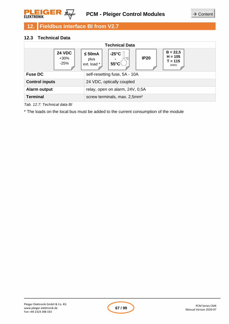
PCM - Pleiger Control Modules → Content
12. Fieldbus interface BI from V2.7
Pleiger Elektronik GmbH & Co. KG www.pleiger-elektronik.de Fon +49 2324 398 333
67 / 99
PCM Series CM4 Manual Version 2020-07
12.3 Technical Data
Technical Data
Fuse DC self-resetting fuse, 5A - 10A
Control inputs 24 VDC, optically coupled
Alarm output relay, open on alarm, 24V, 0,5A
Terminal screw terminals, max. 2,5mm²
Tab. 12.7: Technical data BI
* The loads on the local bus must be added to the current consumption of the module
B = 22,5 H = 105 T = 115
(mm)
IP20 -25°Cxxx
-xxx
55°Cxxx
≤ 50mA
plus
ext. load *
24 VDC
+30%
-25%
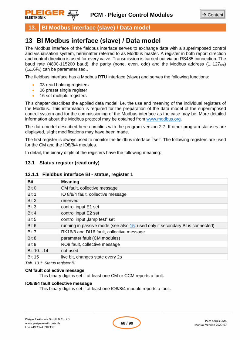
PCM - Pleiger Control Modules → Content
13. BI Modbus interface (slave) / Data model
Pleiger Elektronik GmbH & Co. KG www.pleiger-elektronik.de Fon +49 2324 398 333
68 / 99
PCM Series CM4 Manual Version 2020-07
13 BI Modbus interface (slave) / Data model The Modbus interface of the fieldbus interface serves to exchange data with a superimposed control
and visualisation system, hereinafter referred to as Modbus master. A register in both report direction
and control direction is used for every valve. Transmission is carried out via an RS485 connection. The
baud rate (4800-115200 baud), the parity (none, even, odd) and the Modbus address (1..127dec)
(1h..6Fh) can be parameterised..
The fieldbus interface has a Modbus RTU interface (slave) and serves the following functions:
• 03 read holding registers
• 06 preset single register
• 16 set multiple registers
This chapter describes the applied data model, i.e. the use and meaning of the individual registers of
the Modbus. This information is required for the preparation of the data model of the superimposed
control system and for the commissioning of the Modbus interface as the case may be. More detailed
information about the Modbus protocol may be obtained from www.modbus.org.
The data model described here complies with the program version 2.7. If other program statuses are
displayed, slight modifications may have been made.
The first register is always used to monitor the fieldbus interface itself. The following registers are used
for the CM and the IO8/8/4 modules.
In detail, the binary digits of the registers have the following meaning:
13.1 Status register (read only)
13.1.1 Fieldbus interface BI - status, register 1
Bit Meaning
Bit 0 CM fault, collective message
Bit 1 IO 8/8/4 fault, collective message
Bit 2 reserved
Bit 3 control input E1 set
Bit 4 control input E2 set
Bit 5 control input „lamp test“ set
Bit 6 running in passive mode (see also 15: used only if secondary BI is connected)
Bit 7 RK16/8 and DI16 fault, collective message
Bit 8 parameter fault (CM modules)
Bit 9 RO8 fault, collective message
Bit 10…14 not used
Bit 15 live bit, changes state every 2s
Tab. 13.1: Status register BI
CM fault collective message
This binary digit is set if at least one CM or CCM reports a fault.
IO8/8/4 fault collective message
This binary digit is set if at least one IO8/8/4 module reports a fault.

PCM - Pleiger Control Modules → Content
13. BI Modbus interface (slave) / Data model
Pleiger Elektronik GmbH & Co. KG www.pleiger-elektronik.de Fon +49 2324 398 333
69 / 99
PCM Series CM4 Manual Version 2020-07
Fault on the local data bus
This binary digit is set if at least one module on the local bus replies to broadcast address 0 or
if further faults arise that cannot be allocated to a specific bus participant.
Control input E1 / E2 set
This binary digit is set if control input E1 / E2 has been set (24V).
Control input lamp test set
This binary digit is set if lamp test input has been set.
RK16 / 8 and DI16 fault collective message
This bit is set if at least one RK16 / 8 or DI16 module reports a fault.
Parameter conflict
This bit is set if there is a parameter conflict in at least one CM4 module (see chapter 12.1.7).
RO8 collective message fault
This bit is set if at least one RO8 module reports a fault.
Function monitoring
This bit changes its state every 2s and thus enables a simple check of the availability of the BI
(note: this function is only available from BI version 1.6).
13.1.2 CM3/4 status register
The CM3/4 status register includes the valve position and the valve error messages. The register num-
ber depends on the module address (1-50).
register number = modul address + 1
(50 registers, from no. 2 to no. 51)
The lower-order byte of the register contains the position information:
Value Meaning
0..100 actual position of valves with analog position feedback
(128..228) most significant bit is set while drive is running (add128)
101 drive closed and in a standstill
102 drive neither open nor closed
103 drive open and in a standstill
105 drive in open position, close command received
106 drive in closed position, open command received
107 drive neither open nor closed while closing
108 drive neither open nor closed while opening
109 drive indicating closed position but is still running
110 drive indicating open position but is still running
111 unknown position
Tab. 13.2: Status register CM3/4 position information

PCM - Pleiger Control Modules → Content
13. BI Modbus interface (slave) / Data model
Pleiger Elektronik GmbH & Co. KG www.pleiger-elektronik.de Fon +49 2324 398 333
70 / 99
PCM Series CM4 Manual Version 2020-07
The higher-order byte of the register indicates the error messages:
Bit Meaning Remark
Bit 0
Bit 1
Bit 2
Error (Bit 0-2 binary)
0 = no error
1 = timeout while opening The error flags 1..3 stay set until the cause of the
error is removed or a new command is sent.
Runtime errors generally require resending a
command
2 = timeout while closing
3 = invalid feedback
4 = invalid command
5 = error mimic input open Used with CM4 only
6 = error mimic input close
7 = not used
Bit 3 command close received via mimic in-
put
These status bits indicate the commands given
via the mimic inputs as long as they are set, but at
least for 5s. In the event of an error, wire break
monitoring sets both bits simultaneously. Bit 4 command open received via mimic in-
put
Bit 5 „local / remote“ switch in „local“ position
Bit 6 No AC supply (230 VAC)
Bit 7 offline, no response on local bus
Tab. 13.3: Status register CM3/4 error messages
13.1.2.1 Combining error messages (SCADA-system)
The above mentioned error indications are very detailed. It is not necessary or even recommended to
display all error indications on a SCADA system. A useful combination of different error messages in
several groups is recommended.
For example:
group 1: runtime error = errornumber 1 or 2
group 2: device error = errornumber 3 or 4 and / or Bit 6 (failure 230V)
group 3: „offline“ error = Bit 7
Group 2 and 3 may also be combined. Further fault analysis can be done by means of the status LEDs
of the modules.
Furthermore it is recommended that the SCADA control elements of an actuator are hidden or
greyed if the Bit5 is set (shows "CM module in local mode").
13.1.3 CCM status register
The CCM status register includes the valve position and the valve error messages. The register number
depends on the module address (1-50).
register number = modul address + 1
(50 register, from no. 2 to no. 51)
The lower-order byte of the register indicates the position information:
Value Meaning
0..100 actual position of actuator in %
(128..228) while valve is moving the higher bit is set (+128)
Tab. 13.4: Status register CCM position information
While actuator is moving and also during calibration the most significant Bit in the position byte is set.

PCM - Pleiger Control Modules → Content
13. BI Modbus interface (slave) / Data model
Pleiger Elektronik GmbH & Co. KG www.pleiger-elektronik.de Fon +49 2324 398 333
71 / 99
PCM Series CM4 Manual Version 2020-07
The following positions are displayed.
The higher-order byte of the register indicates the error messages.
Bit Meaning Remark
Bit 0
Bit 1
Bit 2
error messages (Bit 0-2 binary)
0 = no error
1 = timeout while opening The error flags 1..4 stay set until the cause of the
error is removed respectively a new command is
sent. Runtime errors generally require resending
a command. Flag 3 is set on power up and is de-
leted when the counter is referenced the first
time.
2 = timeout while closing
3 = reference run required
4 = invalid position counter value
5 = self-test error
6 = not used
7 = not used
Bit 3 command close received via mimic input The bits 3 and 4 are set as long as the corre-
sponding inputs are set. In any case the bit is set
for at least 5s. Bit 4 command open received via mimic input
Bit 5 „local / remote“ swith in position „local“
Bit 6 no supply for solenoid valves (both 24V DC or 230V AC)
Bit 7 offline, no response on local bus
Tab. 13.5: Status register CCM error and status messages
13.1.4 IO 8/8/4 status register
The IO status registers contain the status of the analog and digital inputs of an IO 8/8/4 module. An IO
8/8/4 module occupies a total of 9 registers. The register number depends on the module address.
The module addresses are in the range of 51 – 60.
register number of the first register = 9*(module address-51) + 52
(90 register, from no. 52 to no. 141)
The first register contains the status of the 8 digital inputs in the lower-order byte and error messages
in the higher-order byte.
Bit Meaning
Bit 0..7 digital input 1..8 set
Bit 8 address was changed after last start up
Bit 9 group error analog inputs
Bit 10 used internally
Bit 15 offline, no response on local bus
Tab. 13.6: Status register IO8/8/4
The following 8 registers contain one each of the 8 measured values as 12 binary digit value (0..20mA
= 0..4000 Incr.)

PCM - Pleiger Control Modules → Content
13. BI Modbus interface (slave) / Data model
Pleiger Elektronik GmbH & Co. KG www.pleiger-elektronik.de Fon +49 2324 398 333
72 / 99
PCM Series CM4 Manual Version 2020-07
NOTICE Validity of the values
An odd analog value indicates that the last measurement has not been updated be-
cause of an invalid measurement.
13.1.5 TII status and input registers
A TII module always uses 9 registers. The first one is the status register. The TII-status register de-
scribes the state of the analog temperature inputs and current outputs of the TII module. The register
number depends on the modules address.
The TII address range is: 51 – 60.
Register number of the first register = 9*(modul address-51) + 52
(90 registers, from no 52 to no 141)
TII and IO8 / 8/4 modules occupy the same register.
The first register contains the states of the 6 temperature measurement inputs and the burden monitor-
ing of the analog outputs.
Bit Meaning
Bit 0…1 analog output 1…2 not connected, wire break or burden resistance to high
Bit 2…7 PT100-[1…6] not connected, wire break or temperature not in measurement range
Bit 8 address was change since last start-up
Bit 9 error of any analog input
Bit 10…11 reserved
Bit 15 offline, no response on local bus
Tab. 13.7: Status register TII
The following 8 registers contain one each of the 8 measured values (PT100: in 1/10 °C; 0..20mA =
0..4000 Incr.)
NOTICE Validity of the values
Valid analog values from the current inputs (4… 20mA) are straight. Odd analog
value indicates that the last measurement has not been updated because of an in-
valid measurement

PCM - Pleiger Control Modules → Content
13. BI Modbus interface (slave) / Data model
Pleiger Elektronik GmbH & Co. KG www.pleiger-elektronik.de Fon +49 2324 398 333
73 / 99
PCM Series CM4 Manual Version 2020-07
13.1.6 RK16/8 status register
The RK status registers contain the status of the digital inputs and error flags of an RK module. An RK
module occupies a total of 2 registers. The register number depends on the module address.
The module addresses are in the range of 61 – 80.
register number of the first status register = 2 * (module address-61) + 203
(40 registers, from no. 203 to no. 242)
The first register shows the error flags in the lower byte and an 8 bit counter value in the upper byte.
Bit Meaninng
Bit 0 fuse is damaged
Bit 1 address button pressed
Bit 2 used internally
Bit 7 offline, no response at the local bus
Bit 8-15 8 Bit counter, all changes of input 1 are counted.
Tab. 13.8: First status register RK16/8
The second register shows the status of the 16 digital inputs.
Bit Bedeutung
Bit 0 digital input 1 (24V = Bit set)
… ...
Bit 15 digital input 16 (24V = Bit set)
Tab. 13.9: Second status register RK16/8
13.1.7 DI16 status register
The DI16 status registers contains the status of the digital inputs and the error flags of a DI16 module.
A DI16 module occupies a total of 2 registers. The register number depends on the module address.
The module addresses are in the range of 61 – 80.
Register number of the first status register = 2 * (module address-81) + 203
(40 registers, from no. 203 to no. 242)
The first register shows the error flags in the lower byte and an 8 bit counter value in the upper byte.
Bit Meaning
Bit 0 not used
Bit 1 address button pressed
Bit 2 used internally
Bit 7 offline, no response at the local bus
Bit 8-15 8 Bit counter, all changes of input 1 are counted.
Tab. 13.10: First status register DI16
The second register shows the status of the 16 digital inputs.
Bit Bedeutung
Bit 0 digital input 1 (24V = Bit set)
… ...
Bit 15 digital input 16 (24V = Bit set)
Tab. 13.11: Second status register DI16
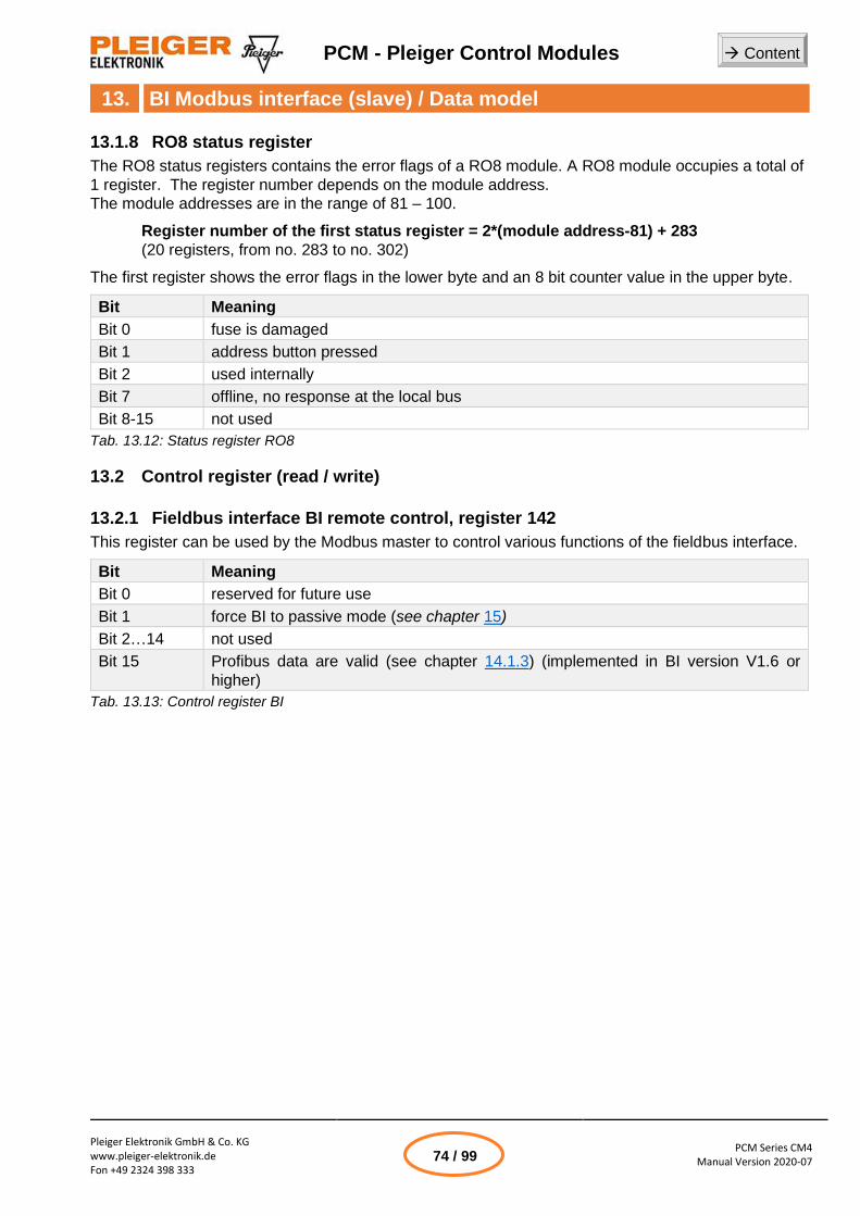
PCM - Pleiger Control Modules → Content
13. BI Modbus interface (slave) / Data model
Pleiger Elektronik GmbH & Co. KG www.pleiger-elektronik.de Fon +49 2324 398 333
74 / 99
PCM Series CM4 Manual Version 2020-07
13.1.8 RO8 status register
The RO8 status registers contains the error flags of a RO8 module. A RO8 module occupies a total of
1 register. The register number depends on the module address.
The module addresses are in the range of 81 – 100.
Register number of the first status register = 2*(module address-81) + 283
(20 registers, from no. 283 to no. 302)
The first register shows the error flags in the lower byte and an 8 bit counter value in the upper byte.
Bit Meaning
Bit 0 fuse is damaged
Bit 1 address button pressed
Bit 2 used internally
Bit 7 offline, no response at the local bus
Bit 8-15 not used
Tab. 13.12: Status register RO8
13.2 Control register (read / write)
13.2.1 Fieldbus interface BI remote control, register 142
This register can be used by the Modbus master to control various functions of the fieldbus interface.
Bit Meaning
Bit 0 reserved for future use
Bit 1 force BI to passive mode (see chapter 15)
Bit 2…14 not used
Bit 15 Profibus data are valid (see chapter 14.1.3) (implemented in BI version V1.6 or
higher)
Tab. 13.13: Control register BI

PCM - Pleiger Control Modules → Content
13. BI Modbus interface (slave) / Data model
Pleiger Elektronik GmbH & Co. KG www.pleiger-elektronik.de Fon +49 2324 398 333
75 / 99
PCM Series CM4 Manual Version 2020-07
13.2.2 CM3/4 control register
A CM3, CM4 control register is used to send a command to a valve. The register number depends on
the module address (1-50).
Register number = module address + 142
(50 registers, from no. 143 to no. 192)
Only the lower-order byte of the valve control register is used.
Value Meaning
0..100 position set point for drives with analog position feedback (%Pos drives)
101 close drive
102 stop drive
103 open drive
104 acknowledge error, erase last command
111 commands by mimic diagram inputs only (not required any longer)
112 Command without function (for pre-setting in the higher-level control system after
restart). Available from BI version 2.B!
Tab. 13.14: Control register CM3/4
NOTICE Compatibility command 111
If command 111 is sent the BI completely passes control to the CM3, CM4 modules.
The CM3, CM4 acts as if there is no BI. Only old CM3 versions V1.6 or lower require
this command to enable the mimic inputs permanently. V1.7 and newer always react
properly on mimic inputs in remote mode and do not require this command any
longer.
Any command change will reset the errors 1..4. To force a command change the following way is sug-
gested:
Set the most significant bit of the command byte to indicate a new command. The CM3, CM4
and CCM will react on this command immediately. The bit should be kept high for at least 1s and
should be reset afterwards.
Besides resetting error conditions restarting a command may be useful in certain applications like actu-
ators that may be operated manually by hand wheel (override). If such a drive is closed by command
and opened manually afterwards a repeated close command will close it again.
example:
• send close command 128+101=229, actuator starts running, wait 1s, send close command 101
• actuator is closed
• actuator is opened manually
• send close command 128+101=229 once more, actuator starts running, wait 1s, send close
command 101
• actuator is closed again
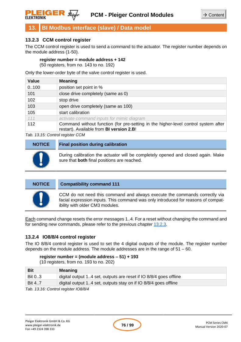
PCM - Pleiger Control Modules → Content
13. BI Modbus interface (slave) / Data model
Pleiger Elektronik GmbH & Co. KG www.pleiger-elektronik.de Fon +49 2324 398 333
76 / 99
PCM Series CM4 Manual Version 2020-07
13.2.3 CCM control register
The CCM control register is used to send a command to the actuator. The register number depends on
the module address (1-50).
register number = module address + 142
(50 registers, from no. 143 to no. 192)
Only the lower-order byte of the valve control register is used.
Value Meaning
0..100 position set point in %
101 close drive completely (same as 0)
102 stop drive
103 open drive completely (same as 100)
105 start calibration
111 activate command inputs for mimic diagram
112 Command without function (for pre-setting in the higher-level control system after
restart). Available from BI version 2.B!
Tab. 13.15: Control register CCM
NOTICE Final position during calibration
During calibration the actuator will be completely opened and closed again. Make
sure that both final positions are reached.
NOTICE Compatibility command 111
CCM do not need this command and always execute the commands correctly via
facial expression inputs. This command was only introduced for reasons of compat-
ibility with older CM3 modules.
Each command change resets the error messages 1..4. For a reset without changing the command and
for sending new commands, please refer to the previous chapter 13.2.3.
13.2.4 IO8/8/4 control register
The IO 8/8/4 control register is used to set the 4 digital outputs of the module. The register number
depends on the module address. The module addresses are in the range of 51 – 60.
register number = (module address – 51) + 193
(10 registers, from no. 193 to no. 202)
Bit Meaning
Bit 0..3 digital output 1..4 set, outputs are reset if IO 8/8/4 goes offline
Bit 4..7 digital output 1..4 set, outputs stay on if IO 8/8/4 goes offline
Tab. 13.16: Control register IO8/8/4

PCM - Pleiger Control Modules → Content
13. BI Modbus interface (slave) / Data model
Pleiger Elektronik GmbH & Co. KG www.pleiger-elektronik.de Fon +49 2324 398 333
77 / 99
PCM Series CM4 Manual Version 2020-07
13.2.5 TII control register
The TII-control register is used to set the 2 analog outputs of the TII module. The register number
depends on the module’s address. The module addresses are in the range of 51 – 60.
register number = (module address – 51) + 193
(10 registers, from no. 193 to no. 202)
Bit Meaning
Bits 15…8 set point for analog output 1;
the output is set to 0 if the data connection between Modbus master and BI or be-
tween BI and TII is interrupted.
Bits 7…0 set point for analog output 2;
the output is set to 0 if the data connection between Modbus maser and BI or be-
tween BI and TII is interrupted.
Tab. 13.17: Control register TII
example:
register output 1 output 2
32FAh 4 mA 20 mA
upper or lower
byte of register output current
00h <1 mA (Aus)
32h 4 mA
7Dh 10 mA
FAh 20 mA
FFh 20,48 mA (ca.)

PCM - Pleiger Control Modules → Content
13. BI Modbus interface (slave) / Data model
Pleiger Elektronik GmbH & Co. KG www.pleiger-elektronik.de Fon +49 2324 398 333
78 / 99
PCM Series CM4 Manual Version 2020-07
13.2.6 RK16/8 control register
The RK 16/8 control register are used to control the relay outputs. Each module uses one register.
The register number depends on the module address.
The module addresses are in the range of 61 – 80.
register number = (module address-61) + 243
(20 registers, from no. 243 to no.262)
Depending on the control register, an output can be set volatile or retentive!
Bit Meaning
Bit 0..7 Set relay output 1..8;
the outputs are reset when the data connection is interrupted
Bit 8..15 Set relay output 1..8;
the outputs remain set even if the data connection is interrupted
Tab. 13.18: Control register RK16/8
13.2.7 DI16 control register
The DI16 module has no control register.
13.2.8 RO8 control register
The RO8 control registers are used to control the relay outputs. Each module uses one register.
The register number depends on the module address.
The module addresses are in the range of 81 – 100.
Register number = (modul address-81) + 263
(20 registers, from no. 263 bis no. 282)
Depending on the control register, an output can be set volatile or retentive!
Bit Meaning
Bit 0..7 Set relay output 1..8;
the outputs are reset when the data connection is interrupted
Bit 8..15 Set relay output 1..8;
the outputs remain set even if the data connection is interrupted
Tab. 13.19: Control register RO8
13.3 Response monitoring
The function of the Modbus or Profibus connection is constantly monitored by the BI module. The BI
module must receive a valid telegram at least every 4s in order to recognize the Modbus connection as
functional. If the Modbus or Profibus connection fails, the BI automatically performs the following func-
tions:
• Send command 111 "Activate command inputs for flow chart control" to all CM modules..
• Set control bits 0..3 of all IO8 / 8/4 to 0, i.e. reset the outputs switched on in this way.
• Set control bits 0..7 of all RK16 / 8 to 0, i.e. reset the outputs switched on in this way.
• Set control bits 0..7 of all RO8 to 0, i.e. reset the outputs switched on in this way..
It is recommended to run at least one poll every second.

PCM - Pleiger Control Modules → Content
13. BI Modbus interface (slave) / Data model
Pleiger Elektronik GmbH & Co. KG www.pleiger-elektronik.de Fon +49 2324 398 333
79 / 99
PCM Series CM4 Manual Version 2020-07
13.4 Extended modbus interface
In addition to the previously provided Modbus registers, the BI version V2.7 and higher also offers ad-
ditional registers with which the parameters can be read and written and the version status of all PCM
modules can be read. The use of these registers is optional and completely independent of the registers
provided so far. The parameters can only be written if the BI has previously been switched to set-up
mode.
13.4.1 Version registers
For each PCM Module one register is provided were the BI writes the version number of the correspond-
ing PCM module. These 80 registers start at register number 400 and are read only registers.
register module
400 BI
401…450 CM with Addr. 1…50
451…460 IO8/8/4, TII with Addr. 51…60
461…480 RK16/8 / DI16 with Addr. 61…80
481…500 RO8 with Addr. 81…100
Tab. 13.20: Version registers
13.4.2 Parameter registers
For each CM4 five registers are reserved that hold the CM4 operating parameters. These 250 registers
start at register 500.
CAUTION Malfunction of the PCM system / Damage to CM4 modules and actuators
These registers must not be written to!

PCM - Pleiger Control Modules → Content
13. BI Modbus interface (slave) / Data model
Pleiger Elektronik GmbH & Co. KG www.pleiger-elektronik.de Fon +49 2324 398 333
80 / 99
PCM Series CM4 Manual Version 2020-07
13.5 Register overwiew
reg.no. status register
bit
high order byte low order byte
15 14 13 12 11 10 9 8 7 6 5 4 3 2 1 0
1 BI-status Live fault para fault p input fault
2 CM module 1 alarm Mo Mc fault position information
3 … 51 CM module 2-50
52
IO8/8/4 / TII module 51
IO8/8/4 / TII module 51
error messages 8 <--digital input--> 1
error messages T6 T5 T4 T3 T2 T1 IA2 IA1
53 IO8/8/4 / TII module 51 analog input 1 / PT 100-1
54 IO8/8/4 / TII module 51 analog input 2 / PT 100-2
55-59 to
60 IO8/8/4 / TII module 51 analog input 8 / current input 2
61-69 …
133-141
IO8/8/4 module 52-60
TII module 52-60
reg.no. control register
bit
high order byte low order byte
15 14 13 12 11 10 9 8 7 6 5 4 3 2 1 0
142 BI-control VP P Res
143 CM module 1 drive commands
144 …
192 CM module 2-50
193 IO8/8/4 module 51 4<dig.Ausg.>1 4<dig.Ausg.>1
194 TII module 51 Analog output value channel 1 Analog output value channel 2
195-196
…
201-202
IO8/8/4 module 52-60
TII module 52-60
reg.no. status register
bit
high order byte low order byte
15 14 13 12 11 10 9 8 7 6 5 4 3 2 1 0
203 RK16/8 module 61
DI16 module 61
Zählwert Dig-In 1 error messages
204 16 <--- digital inputs ---> 9 8 <--- digital inputs ---> 1
205-206
…
241-242
RK16/8 module 62-80
DI16 module 62-80
reg.no. control register
bit
high order byte low order byte
15 14 13 12 11 10 9 8 7 6 5 4 3 2 1 0
243 RK16/8 module 61 8 <-- digit. Ausgänge rem.--> 1 8 <-- digit. Ausgänge vol.--> 1
244 … 262 RK16/8 module 62-80
263 RO8 module 81 8 <-- digit. Ausgänge rem.--> 1 8 <-- digit. Ausgänge vol.--> 1
264 … 282 RO8 module 82-100
reg.no. status register
bit
high order byte low order byte
15 14 13 12 11 10 9 8 7 6 5 4 3 2 1 0
283 RO8 module 81 Error messages
284 … 302 RO8 module 82-100
currently not used =
Tab. 13.21: Register overview
Mo = mimic order open, Mc = mimic order close
p = runs in passive mode / P = force passive mode
VP = Data valid bit for Profibus / CM CM3, CM4, CM4-D, CCM

PCM - Pleiger Control Modules → Content
14. BI Profibus DP interface (slave)
Pleiger Elektronik GmbH & Co. KG www.pleiger-elektronik.de Fon +49 2324 398 333
81 / 99
PCM Series CM4 Manual Version 2020-07
14 BI Profibus DP interface (slave) The Profibus DPV0 interface is available as an alternative to the Modbus and can be chosen via the
setup menu of the fieldbus interface (BI). Automatic baud rate identification is used. Baud rates between
9600 baud and 1.5 Mbaud are permissible. If required a bus terminator (in accordance with the Profibus
standard) can be connected via a miniature two-pole switch in the front of the housing.
The advanced V1 and V2 services are not available. Differing from the Profibus standard an inexpensive
screw-type terminal is used for the electrical connection instead of a sub-D connector. More detailed
information about the Profibus protocol may be obtained from the standard EN 50170 or from the „Pro-
fibus Nutzer Organisation“ (PNO, www.profibus.com).
14.1 Profibus Data model
For compatibility reasons the same data model is used as for the Modbus. 16 binary digit-wide data
words are used instead of the Modbus registers. On account of the maximum telegram length of 244
bytes a maximum of 7 IO- or TII modules can be used for the Profibus protocol. The data model is
described in the “PE_PCMV2.gsd“ GSD file (or newer versions). The meaning of the individual data
words corresponds to those in the registers for the Modbus protocol.
To avoid unnecessary data transfer the BI module is setup as a modular station. The following modules
are available.
Module 1 1x BI status and control 1 word read 1 word write
Module 2 5x CM4/CCM status and control 5 words read 5 words write
Module 3 10x CM4/CCM status and control 10 words read 10 words write
Module 4 1x IO8/8/4 oder TII status and control 9 words read 1 word write
Module 5 1x RK status and control 2 words read 1 word write
Module 6 5x RK status and control 10 words read 5 words write
Module 7 1x DI16 status 2 words read
Module 8 5x DI16 status 10 words read
Module 9 1x RO8 status and control 1 word read 1 word write
Module 10 5x RO8 status and control 5 words read 5 words write
Tab. 14.1: Available modules BI
Module 1 must always be inserted first, followed by up to 50 CM modules, up to 7 IO8/8/4 or TII modules,
a maximum of 20 RK16/8 relay cards or 20 DI16 modules and a maximum of 20 RO8 relay output
modules.
14.1.1 Fieldbus interface to superimposed control system (status words)
data word Meaning
1 status fieldbus interface
1 each status CM, address 1..50
9 each status IO8/8/4 / TII, address 51..57
2 each status RK16/8, address 61..80
2 each status DI16, address 61..80
1 each status RO8, address 81..100
Tab. 14.2: Status words BI to superimposed control system

PCM - Pleiger Control Modules → Content
14. BI Profibus DP interface (slave)
Pleiger Elektronik GmbH & Co. KG www.pleiger-elektronik.de Fon +49 2324 398 333
82 / 99
PCM Series CM4 Manual Version 2020-07
14.1.2 Superimposed control system to fieldbus interface (control words)
data word Meaning
1 command fieldbus interface
1 each command CM4/CCM, address 1..50
1 each command IO8/8/4 / TII, address 51..57
1 each command RK16/8, address 61..80
1 each command RO8, address 81..100
Tab. 14.3: Control words BI with superimposed control
14.1.3 Data valid bit
some Profibus DP masters, data is transferred without errors even if the supervisory controller is
stopped or reset. In this case all control words are preset with 0. This behavior does not make sense
for the PCM modules and can lead to undesired operating states. Therefore, bit 15 of the BI control
word is used as the "Data Valid Bit". As long as this bit is not set, the entire Profibus connection is
considered invalid.
This function is available from BI software version V1.6. In order to remain compatible with previous
versions, the "Data Valid Bit" is only evaluated if bit "0" of the first parameter byte is set to 1 in the "user
param data" in the Profibus parameterization.
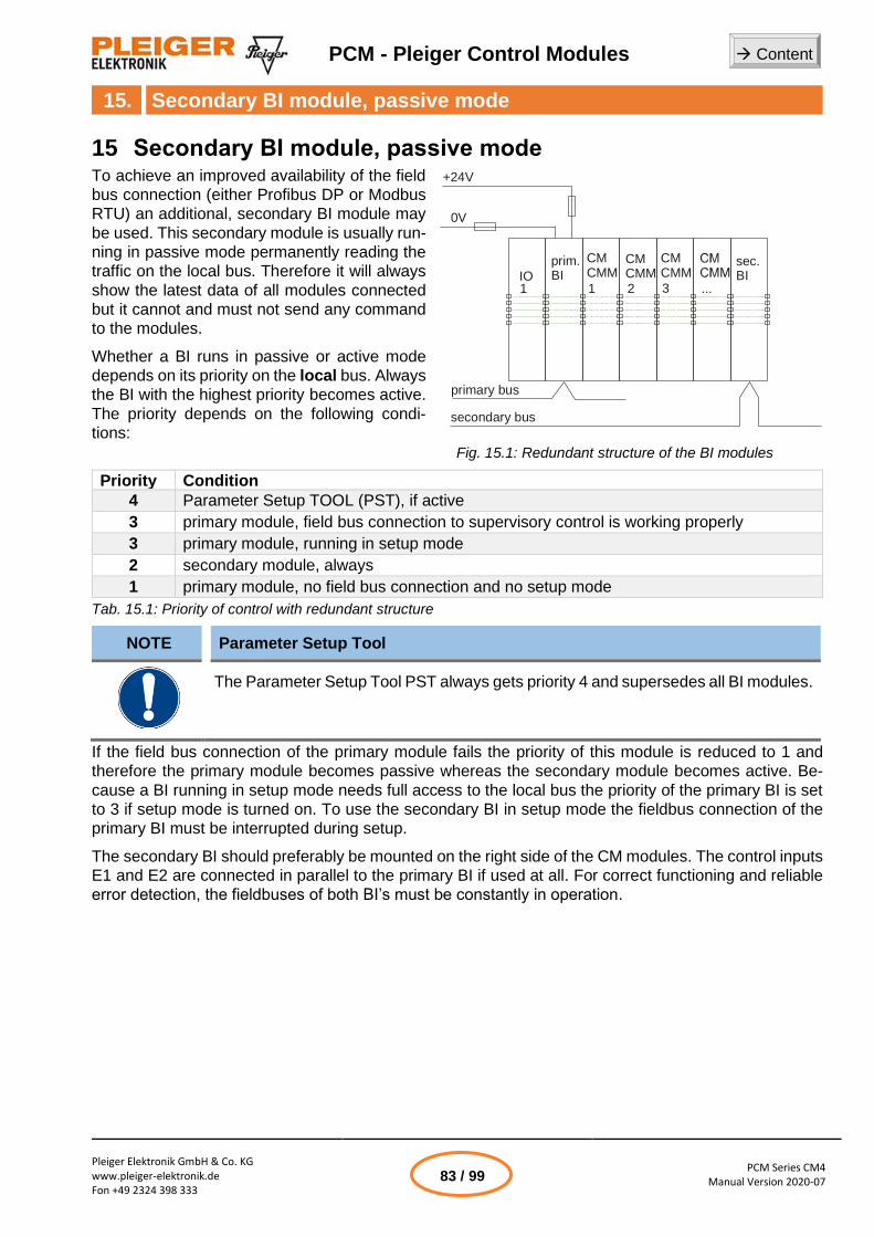
PCM - Pleiger Control Modules → Content
15. Secondary BI module, passive mode
Pleiger Elektronik GmbH & Co. KG www.pleiger-elektronik.de Fon +49 2324 398 333
83 / 99
PCM Series CM4 Manual Version 2020-07
15 Secondary BI module, passive mode To achieve an improved availability of the field
bus connection (either Profibus DP or Modbus
RTU) an additional, secondary BI module may
be used. This secondary module is usually run-
ning in passive mode permanently reading the
traffic on the local bus. Therefore it will always
show the latest data of all modules connected
but it cannot and must not send any command
to the modules.
Whether a BI runs in passive or active mode
depends on its priority on the local bus. Always
the BI with the highest priority becomes active.
The priority depends on the following condi-
tions:
Fig. 15.1: Redundant structure of the BI modules
Priority Condition
4 Parameter Setup TOOL (PST), if active
3 primary module, field bus connection to supervisory control is working properly
3 primary module, running in setup mode
2 secondary module, always
1 primary module, no field bus connection and no setup mode
Tab. 15.1: Priority of control with redundant structure
NOTE Parameter Setup Tool
The Parameter Setup Tool PST always gets priority 4 and supersedes all BI modules.
If the field bus connection of the primary module fails the priority of this module is reduced to 1 and
therefore the primary module becomes passive whereas the secondary module becomes active. Be-
cause a BI running in setup mode needs full access to the local bus the priority of the primary BI is set
to 3 if setup mode is turned on. To use the secondary BI in setup mode the fieldbus connection of the
primary BI must be interrupted during setup.
The secondary BI should preferably be mounted on the right side of the CM modules. The control inputs
E1 and E2 are connected in parallel to the primary BI if used at all. For correct functioning and reliable
error detection, the fieldbuses of both BI’s must be constantly in operation.
IO
prim.BI
CMCMM
CMCMM
1 21
sec.BI
CMCMM
3 ...
+24V
0V
primary bus
secondary bus

PCM - Pleiger Control Modules → Content
15. Secondary BI module, passive mode
Pleiger Elektronik GmbH & Co. KG www.pleiger-elektronik.de Fon +49 2324 398 333
84 / 99
PCM Series CM4 Manual Version 2020-07
15.1 Parameterization of the secondary BI module
The secondary module is set to a fieldbus address "actual address + 80h". Thus, e.g. the secondary
module with fieldbus address 1 has the setting 1 + 80h = 81h. If both BI’s are connected to different bus
masters, both BI’s can use the same actual fieldbus address. The primary and secondary module differ
only in this address setting.
NOTE Compatibility
The primary and secondary module function is only available from software version
2.0 of the BI module!
15.2 Fieldbus interface BI status, register 1 (read only)
One entry is added to this register. As long as the BI is running in passive mode all data are valid but
no command will be sent to the modules.
Bit Meaning
Bit 6 running in passive mode
Tab. 15.2: Status register secondary BI
15.3 Fieldbus interface BI remote control, register 142 (read/write)
One entry is added to this register. For test purpose the BI can be forced into passive mode. The sec-
ondary BI will than change to active mode.
Bit Meaning
Bit 1 passive Betriebsart einschalten
Tab. 15.3: Control register secondary BI
NOTE Passive mode
Only one single BI must be set to passive mode.
15.4 Operating redundant BI
Both master interface settings should be (but don’t have to be) identical. If two separate bus cables are
used even the slave addresses may and should be the same. The master software should treat both
BIs as well as the connected modules identically. There is no need to send commands to the passive
BI as this BI can’t send commands to the connected modules. Anyhow you may do so if it is more
convenient. The passive flag in the BI status register should be indicated to the user. Of course both
masters must poll the primary and the secondary BI permanently. Otherwise a failure of the secondary
bus may not be noticed.
For test purpose the master should be able to stop polling the primary bus. In this case the secondary
BI must indicate that it turned to active state a few seconds later. If turning off the primary master is not
possible the primary BI can be forced to passive mode by setting the corresponding bit in the control
register.
15.5 Alarm output
The alarm output of the passive BI is always closed that means an alarm is never signalised. The active
BI behaves like a standard BI.

PCM - Pleiger Control Modules → Content
16. Parameter-Setup-Tool (PST)
Pleiger Elektronik GmbH & Co. KG www.pleiger-elektronik.de Fon +49 2324 398 333
85 / 99
PCM Series CM4 Manual Version 2020-07
16 Parameter-Setup-Tool (PST) The Parameter Setup Tool (PST) is a small handheld device equipped
with a four line LCD display and five buttons. By means of a spiral cable
with a RJ11 plug it can be plugged in the PST-C connector module and
thus connected with the local PMC bus. The PST is supplied by the
local bus and has full access to the local data bus and to the connected
CM4 modules. Of course the CM4 must be addressed in the usual way
either using a BI or the PST.
NOTE Software version
If a BI module is used together with CM4 and PST
the software version of this BI must be V2.7 or higher.
Otherwise the functions described here are not or
only partially available.
The PST may be used in combination with one or two BI‘s on the bus.
For security reasons, the PST may only be connected to the PST-C for
parameterization of the system. The PST-C can remain permanently
connected to the local bus of the PCM modules.
dimensions:
PST 165 x 80 x 28 mm
PST-C 85 x 70,4 x 22,5 mm
16.1 PST becomes active bus master on the local bus
CAUTION Control system loses control function
As soon as a submenu is selected, the PST changes to active mode as bus master.
The supervising control system can no longer control the modules.
• Changes and parameterization must only be carried out by trained staff.
• Bear in mind any consequence that may occur when the control system has no
influence and possibility of intervention on the system.
• After finishing your work, select the main menu or disconnect the PST from the
bus.
The PST may be connected to a running system and doesn’t interfere with the normal function of the
system. But if any sub-menu of the PST is called the BIs become passive and the PST acts as a Bus
master. The lower decimal points of the BIs turn on and indicate the passive state.
If parameters are sent to a CM4 module they will also be sent to the BIs and stored in a non-volatile
memory. In this way the parameter set can automatically be restored if a CM4 has to be replaced.
All CM4 are permanently requested by the PST in the same way a BI would do. All other PCM modules
like IO 8/8/4 or RK 16/8 are not served by the PST. The output signals of those modules are reset if this
function is used.
Fig. 15.1: PST with PST-C

PCM - Pleiger Control Modules → Content
16. Parameter-Setup-Tool (PST)
Pleiger Elektronik GmbH & Co. KG www.pleiger-elektronik.de Fon +49 2324 398 333
86 / 99
PCM Series CM4 Manual Version 2020-07
16.2 PST main menu
PCM Set-Up Tool V1.2
Pleiger Elektronik
1: Parameter set-up
2: Address set-up
If the PST is plugged in it shows the main menu. As long as the PST shows this main menu it has no
access to the local Bus of the PCM system and the system operates as usual.
This menu is used to call one of two functions, either to set the CM addresses or to change the CM
parameter. Use the arrow keys and to select the desired function and call the function by pressing the OK-Button. Alternatively pressing the arrow key for a longer time will call function 1.
(Notice: The PST distinguishes two ways of pressing a button, a short click on a button lasting less than
0,7s and pressing the button for more than 0,7s. The short click has the meaning OK or Acknowledge
whereas a long press means escape or abort.)
As soon as one of the sub menus is selected, the PST takes control to the local Bus and all BI turn
passive and do not communicate to the connected modules.
NOTE Terminating setup
If the PST is no longer needed, select the main menu or disconnect the PST from
the local Bus.
The PST automatically returns to the main menu if none of the five buttons is pressed
for 3 minutes (from version 1.1 on only).
16.3 „Address Set-Up“ menu
This function serves to set or change the address of a CM4 module. The way to set an address is similar
to the BI in setup mode.
address set ??
first free addr. 1
address offset 0
new address 1
Turn CM4 to remote mode and then press the open / close command switch to show some more infor-
mation about this node.
address set Vx.y aa
The version of the CM4 software Vx.y as well as the module address „aa“ are displayed. If no address
is set „no“ is displayed.
first free addr aa
The lowest unused address is shown here. Usually this address will be used for the selected node.
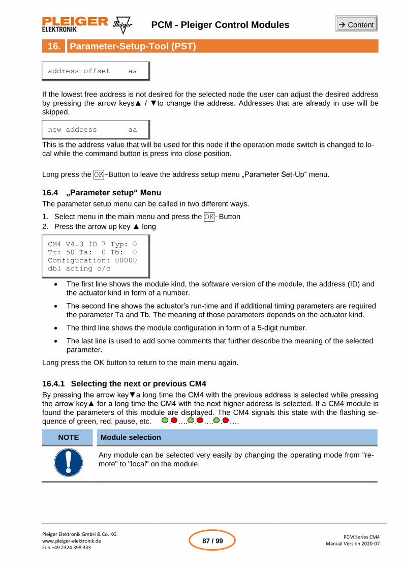
PCM - Pleiger Control Modules → Content
16. Parameter-Setup-Tool (PST)
Pleiger Elektronik GmbH & Co. KG www.pleiger-elektronik.de Fon +49 2324 398 333
87 / 99
PCM Series CM4 Manual Version 2020-07
address offset aa
If the lowest free address is not desired for the selected node the user can adjust the desired address
by pressing the arrow keys / to change the address. Addresses that are already in use will be
skipped.
new address aa
This is the address value that will be used for this node if the operation mode switch is changed to lo-
cal while the command button is press into close position.
Long press the OK-Button to leave the address setup menu „Parameter Set-Up“ menu.
16.4 „Parameter setup“ Menu
The parameter setup menu can be called in two different ways.
1. Select menu in the main menu and press the OK-Button
2. Press the arrow up key long
CM4 V4.3 ID 7 Typ: 0
Tr: 50 Ta: 0 Tb: 0
Configuration: 00000
dbl acting o/c
• The first line shows the module kind, the software version of the module, the address (ID) and
the actuator kind in form of a number.
• The second line shows the actuator’s run-time and if additional timing parameters are required
the parameter Ta and Tb. The meaning of those parameters depends on the actuator kind.
• The third line shows the module configuration in form of a 5-digit number.
• The last line is used to add some comments that further describe the meaning of the selected
parameter.
Long press the OK button to return to the main menu again.
16.4.1 Selecting the next or previous CM4
By pressing the arrow keya long time the CM4 with the previous address is selected while pressing
the arrow key for a long time the CM4 with the next higher address is selected. If a CM4 module is
found the parameters of this module are displayed. The CM4 signals this state with the flashing se-
quence of green, red, pause, etc. . …. . …. . ….
NOTE Module selection
Any module can be selected very easily by changing the operating mode from "re-
mote" to "local" on the module.

PCM - Pleiger Control Modules → Content
16. Parameter-Setup-Tool (PST)
Pleiger Elektronik GmbH & Co. KG www.pleiger-elektronik.de Fon +49 2324 398 333
88 / 99
PCM Series CM4 Manual Version 2020-07
16.4.2 Selecting a parameter
The desired parameter can be selected using the arrow keys (short press). To change from selection mode to editing mode, press the OK button once briefly. The cursor now changes its appearance. In-
stead of a blinking rectangle, it is represented by a fine underline.
16.4.3 Changing the parameter
The / arrow keys are used to increase or decrease the value,
the / arrow keys are used to select the digit that shall be changed.
If the desired value of the parameter is set press the OK button shortly to confirm this parameter and to
send it to BI and CM4. The edit mode is left and the selection mode is turned on again. The appearance
of the cursor changes to a blinking cursor again.
If the modified parameter value shall be discarded in edit mode just press the OK button long. The edit
mode will be left but the parameter value stays unchanged.
16.4.4 Actuator type
Depending on the used control module (CM3, CM4-D or CM4) the selection of the actuator type differs.
On the CM3 module the drive type corresponds to the setting of the 4 DIP-switches, on the CM4-D
module on the first 4 DIP-switches (of 6) and on the CM4 module to the parametrizaton of the BI module.
For the CM4 module, in addition to the defined actuator types with their corresponding control functions
(see chapter 4.2), there is the so-called standard type or default value, which is displayed on the PST
with * 0. This standard type characterizes the factory settings of the parameter memory or a deleted
parameter area in the memory. If this standard value is not changed, the module will not work. There-
fore, this standard value must be overwritten with the correct value in any case, only then will the
functionality of the module be released.
16.4.5 Timing parameter
The time parameters Tr, Ta and Tb of the individual actuator types are explained in the description of
the CM4 module (see chapter 4.2).
16.5 Teach-in
The CM4 from version 4.1 has a learning drive function to set the time parameters automatically. The
learn run enables the time parameters Tr, Ta and Tb to be set in a simple manner. As described above,
the meaning of the three parameters depends on the drive type (see chapter 4.2).
The Teach-In function is started if:
• the parameter Tr has been set to 0 and the open command is set in local operation mode.
• The CM4 is selected by the PST and the open command is set in local operation mode.
The actuator first opens completely, stays in open position for a few s and then closes again. If an
analog position indication is used the actuator stops at 30% while opening and also while closing. Finally
the parameters are calculated, stored in EEPROM and are also sent to the BI. The BI once indicates
E. E. for a second. If a BI is used the version must be 2.6 or higher, otherwise the BI will indicate a
parameter fault PF.
For actuators that close or open successively the pulse and pause time is set in such a way that the to-
tal close time is doubled. That means that the pause time is twice as high as the pulse time.
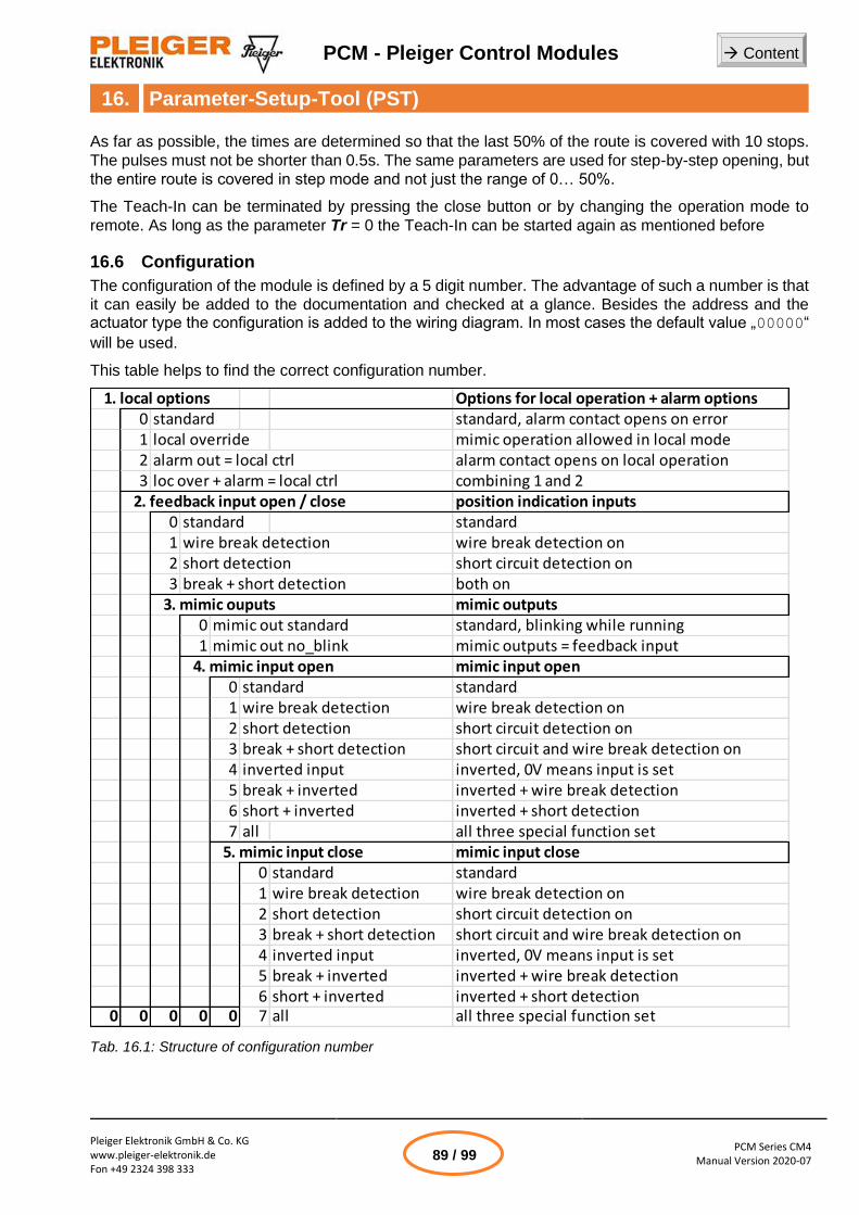
PCM - Pleiger Control Modules → Content
16. Parameter-Setup-Tool (PST)
Pleiger Elektronik GmbH & Co. KG www.pleiger-elektronik.de Fon +49 2324 398 333
89 / 99
PCM Series CM4 Manual Version 2020-07
As far as possible, the times are determined so that the last 50% of the route is covered with 10 stops.
The pulses must not be shorter than 0.5s. The same parameters are used for step-by-step opening, but
the entire route is covered in step mode and not just the range of 0… 50%.
The Teach-In can be terminated by pressing the close button or by changing the operation mode to
remote. As long as the parameter Tr = 0 the Teach-In can be started again as mentioned before
16.6 Configuration
The configuration of the module is defined by a 5 digit number. The advantage of such a number is that
it can easily be added to the documentation and checked at a glance. Besides the address and the actuator type the configuration is added to the wiring diagram. In most cases the default value „00000“
will be used.
This table helps to find the correct configuration number.
Tab. 16.1: Structure of configuration number
1. local options Options for local operation + alarm options0 standard standard, alarm contact opens on error1 local override mimic operation allowed in local mode2 alarm out = local ctrl alarm contact opens on local operation3 loc over + alarm = local ctrl combining 1 and 2
2. feedback input open / close position indication inputs0 standard standard1 wire break detection wire break detection on2 short detection short circuit detection on3 break + short detection both on
3. mimic ouputs mimic outputs0 mimic out standard standard, blinking while running1 mimic out no_blink mimic outputs = feedback input
4. mimic input open mimic input open0 standard standard1 wire break detection wire break detection on2 short detection short circuit detection on3 break + short detection short circuit and wire break detection on4 inverted input inverted, 0V means input is set5 break + inverted inverted + wire break detection6 short + inverted inverted + short detection7 all all three special function set
5. mimic input close mimic input close0 standard standard1 wire break detection wire break detection on2 short detection short circuit detection on3 break + short detection short circuit and wire break detection on4 inverted input inverted, 0V means input is set5 break + inverted inverted + wire break detection6 short + inverted inverted + short detection
0 0 0 0 0 7 all all three special function set

PCM - Pleiger Control Modules → Content
16. Parameter-Setup-Tool (PST)
Pleiger Elektronik GmbH & Co. KG www.pleiger-elektronik.de Fon +49 2324 398 333
90 / 99
PCM Series CM4 Manual Version 2020-07
Tab. 16.2: Parameter input level mimic
The reaction of the CM4 on the mimic input level depends on the parameter setting. The behaviour of
the command inputs close and open is identical.
16.6.1 Copy and paste
Long press the arrow key to copy all parameters of the latest parameter set that has been confirmed
to the selected node. Long press the arrow key to replace all parameter of the selected node by
default values
parameter input level alarm com-mand
0 standard break OFF OFF
low OFF OFF
high OFF ON
short OFF ON
3 break ON OFF
break+short low OFF OFF
high OFF ON
short ON OFF
4 break OFF ON
inverted low OFF ON
high OFF OFF
short OFF OFF
7 break ON ON
inverted+ low OFF ON
break+short high OFF OFF
short ON ON

PCM - Pleiger Control Modules → Content
17. PCM modules, available versions
Pleiger Elektronik GmbH & Co. KG www.pleiger-elektronik.de Fon +49 2324 398 333
91 / 99
PCM Series CM4 Manual Version 2020-07
17 PCM modules, available versions CM3 modules should no longer be used for new installations. This applies particularly to special versions
xx110 to xx180.
17.1 CM3
CM3 is no longer recommended for new installations!
Article number Function
9341100100 Standard device as described in the manual
9341100110 CM3 with control functions for hydraulic actuators with 24V solenoid valves
9341100120 CM3 for spring close actuators with separated hydraulic unit
9341100140 Like standard device but extended operation mode 1+2 is already set
9341100150 Like standard device but extended operation mode 1+3 is already set
9341100160 Device with wire break detection and extended operation mode 1+2 is already set
9341100170 Device with wire break detection and extended operation mode 1+4 is already set
9341100180 Like standard device but extended operation mode 1 is already set
9341100190 Standard device but mimic outputs indicate drive position only, without blinking
Tab. 17.1: Versions of CM3
17.2 CM4
Article number Function
9341100800 Standard device as described in this manual.
9341100810 Special version for control function 18 and 19.
9341100850 CM4-D, CM4 with 6 DIP-switches for 16 actuator types and 2 additional operating
modes
Tab. 17.2: Versions of CM4
17.3 BI
Article number Function
9341100200 Standard device as described in this manual, provides Modbus + Profibus inter-
face
9341100250 Simplified version, provides Modbus interface only
Tab. 17.3: Versions of BI
17.4 IO8/8/4
Article number Function
9341100300 Standard device as described in this manual.
Tab. 17.4: Versions of IO8/8/4
17.5 TII
Article number Function
9341100600 Standard device as described in this manual.
Tab. 17.5: Versions of TII
17.6 RK16/8
Article number Function
9341100400 Standard device as described in this manual.
Tab. 17.6: Versions of RK16/8

PCM - Pleiger Control Modules → Content
17. PCM modules, available versions
Pleiger Elektronik GmbH & Co. KG www.pleiger-elektronik.de Fon +49 2324 398 333
92 / 99
PCM Series CM4 Manual Version 2020-07
17.7 CCM
Article number Function
9341100500 Standard device as described in this manual.
Tab. 17.7: Versions of CCM
17.8 DI16
Article number Function
9341101100 Standard device as described in this manual.
Tab. 17.8: Versions of DI16
17.9 RO8
Article number Function
9341101200 Standard device as described in this manual.
Tab. 17.9: Versions of RO8

PCM - Pleiger Control Modules → Content
18. List of tables
Pleiger Elektronik GmbH & Co. KG www.pleiger-elektronik.de Fon +49 2324 398 333
93 / 99
PCM Series CM4 Manual Version 2020-07
18 List of tables Tab. 3.1: Bus connector assignment .................................................................................................... 7
Tab. 4.1: CM4 controls ....................................................................................................................... 10
Tab. 4.2: CM4 LED red/green ............................................................................................................ 24
Tab. 4.3: CM4 LED yellow .................................................................................................................. 24
Tab. 4.4: Wire break and short circuit detection of the mimic inputs ................................................... 25
Tab. 4.5: Standard command input CM4 ............................................................................................ 25
Tab. 4.6: Inverted command input CM4 ............................................................................................. 26
Tab. 4.7: Wire break / short circuit monitoring of the feedback inputs ................................................. 27
Tab. 4.8: Display wire break- / short circuit errors............................................................................... 27
Tab. 4.9: Example display wire break ................................................................................................. 27
Tab. 4.10: Terminal assignment CM4................................................................................................. 29
Tab. 4.11: State table for spring close actuators with seperate hydraulic unit ..................................... 30
Tab. 4.12: Technical Data CM4 .......................................................................................................... 31
Tab. 5.1: Switch position for extended operating modes CM4-D ........................................................ 32
Tab. 5.2: Type of actuator CM4-D ...................................................................................................... 33
Tab. 6.1: Controls CCM ..................................................................................................................... 34
Tab. 6.2: CCM LED red/green ............................................................................................................ 36
Tab. 6.3: CCM LED yellow ................................................................................................................. 36
Tab. 6.4: Steps of the CCM calibration run ......................................................................................... 37
Tab. 6.5: Terminal assignment CCM .................................................................................................. 38
Tab. 6.6: Technicle data flowmeter .................................................................................................... 39
Tab. 6.7: Technical Data CCM ........................................................................................................... 39
Tab. 7.1: RK16/8 status LED yellow ................................................................................................... 40
Tab. 7.2: Terminal assignment RK16/8 .............................................................................................. 41
Tab. 7.3: Bus clamp RK16/8 .............................................................................................................. 41
Tab. 7.4: Technical Data RK16/8 ....................................................................................................... 42
Tab. 8.1: Address setting IO8/8/4 ....................................................................................................... 43
Tab. 8.2: IO8/8/4 LED green .............................................................................................................. 43
Tab. 8.3: IO8/8/4 LED gelb ................................................................................................................. 44
Tab. 8.4: Terminal assigment IO8/8/4 ................................................................................................ 45
Tab. 8.5: Technical Data IO8/8/4 ........................................................................................................ 46
Tab. 9.1: Address setting TII .............................................................................................................. 47
Tab. 9.2: TII LED green ...................................................................................................................... 47
Tab. 9.3: TII LED yellow ..................................................................................................................... 48
Tab. 9.4: TII LED red .......................................................................................................................... 48

PCM - Pleiger Control Modules → Content
18. List of tables
Pleiger Elektronik GmbH & Co. KG www.pleiger-elektronik.de Fon +49 2324 398 333
94 / 99
PCM Series CM4 Manual Version 2020-07
Tab. 9.5: TII Status-LED yellow .......................................................................................................... 48
Tab. 9.6: Terminal assignment TII ...................................................................................................... 49
Tab. 9.7: Technical Data TII ............................................................................................................... 50
Tab. 10.1: DI16 status-LED yellow ..................................................................................................... 51
Tab. 10.2: Terminal assignment DI16................................................................................................. 52
Tab. 10.3: Technical Data DI16 .......................................................................................................... 53
Tab. 11.1: RO8 status-LED yellow ..................................................................................................... 54
Tab. 11.2: Terminal assignment RO8 ................................................................................................. 55
Tab. 11.3: Technical Data RO8 .......................................................................................................... 56
Tab. 12.1: Parameterisation fieldbus .................................................................................................. 58
Tab. 12.2: Cases with parameter deviations BI / CM4 ........................................................................ 61
Tab. 12.3: BI LEDs ............................................................................................................................. 63
Tab. 12.4: Quick Close functions (up to V2.9) .................................................................................... 65
Tab. 12.5: Quick Close functions (from V2.A) ..................................................................................... 65
Tab. 12.6: Terminal assignment BI ..................................................................................................... 66
Tab. 12.7: Technical data BI .............................................................................................................. 67
Tab. 13.1: Status register BI ............................................................................................................... 68
Tab. 13.2: Status register CM3/4 position information ........................................................................ 69
Tab. 13.3: Status register CM3/4 error messages .............................................................................. 70
Tab. 13.4: Status register CCM position information .......................................................................... 70
Tab. 13.5: Status register CCM error and status messages ............................................................... 71
Tab. 13.6: Status register IO8/8/4 ...................................................................................................... 71
Tab. 13.7: Status register TII .............................................................................................................. 72
Tab. 13.8: First status register RK16/8 ............................................................................................... 73
Tab. 13.9: Second status register RK16/8 .......................................................................................... 73
Tab. 13.10: First status register DI16 ................................................................................................. 73
Tab. 13.11: Second status register DI16 ............................................................................................ 73
Tab. 13.12: Status register RO8 ......................................................................................................... 74
Tab. 13.13: Control register BI ........................................................................................................... 74
Tab. 13.14: Control register CM3/4 .................................................................................................... 75
Tab. 13.15: Control register CCM ....................................................................................................... 76
Tab. 13.16: Control register IO8/8/4 ................................................................................................... 76
Tab. 13.17: Control register TII........................................................................................................... 77
Tab. 13.18: Control register RK16/8 ................................................................................................... 78
Tab. 13.19: Control register RO8 ....................................................................................................... 78
Tab. 13.20: Version registers ............................................................................................................. 79

PCM - Pleiger Control Modules → Content
18. List of tables
Pleiger Elektronik GmbH & Co. KG www.pleiger-elektronik.de Fon +49 2324 398 333
95 / 99
PCM Series CM4 Manual Version 2020-07
Tab. 13.21: Register overview ............................................................................................................ 80
Tab. 14.1: Available modules BI ......................................................................................................... 81
Tab. 14.2: Status words BI to superimposed control system .............................................................. 81
Tab. 14.3: Control words BI with superimposed control ...................................................................... 82
Tab. 15.1: Priority of control with redundant structure ........................................................................ 83
Tab. 15.2: Status register secondary BI ............................................................................................. 84
Tab. 15.3: Control register secondary BI ............................................................................................ 84
Tab. 16.1: Structure of configuration number ..................................................................................... 89
Tab. 16.2: Parameter input level mimic .............................................................................................. 90
Tab. 17.1: Versions of CM3 ................................................................................................................ 91
Tab. 17.2: Versions of CM4 ................................................................................................................ 91
Tab. 17.3: Versions of BI .................................................................................................................... 91
Tab. 17.4: Versions of IO8/8/4 ........................................................................................................... 91
Tab. 17.5: Versions of TII ................................................................................................................... 91
Tab. 17.6: Versions of RK16/8 ........................................................................................................... 91
Tab. 17.7: Versions of CCM ............................................................................................................... 92
Tab. 17.8: Versions of DI16 ................................................................................................................ 92
Tab. 17.9: Versions of RO8 ................................................................................................................ 92

PCM - Pleiger Control Modules → Content
19. List of figures
Pleiger Elektronik GmbH & Co. KG www.pleiger-elektronik.de Fon +49 2324 398 333
96 / 99
PCM Series CM4 Manual Version 2020-07
19 List of figures Fig. 3.1: Bus connector ........................................................................................................................ 7
Fig. 3.2: Adapting cable ....................................................................................................................... 7
Fig. 3.3: Extension cable ...................................................................................................................... 8
Fig. 3.4: Adapting cable for RK16/8 ...................................................................................................... 8
Fig. 3.5: End holder .............................................................................................................................. 8
Fig. 3.6: Noise suppression filter .......................................................................................................... 8
Fig. 3.7: CM-ExE capacitor module ...................................................................................................... 9
Fig. 3.8: PST-C .................................................................................................................................... 9
Fig. 4.1: CM4 ..................................................................................................................................... 10
Fig. 4.3: Wire break and short circuit detection of the mimic inputs .................................................... 25
Fig. 4.2: Circuit diagram input circuit .................................................................................................. 25
Fig. 4.4: Wire break and short circuit monitoring of the feedback inputs ............................................. 27
Fig. 4.5: Circuit diagram feedback input ............................................................................................. 27
Fig. 4.6: Side view CM4 ..................................................................................................................... 29
Fig. 4.7: Terminal CM4 ....................................................................................................................... 29
Fig. 4.8: Connection of Ex actuators .................................................................................................. 30
Fig. 4.9: Connection of spring close actuators with seperate hydraulic unit ........................................ 30
Fig. 4.10: Fuses CM4 ......................................................................................................................... 31
Fig. 5.1: CM4-D .................................................................................................................................. 32
Fig. 5.2: DIP switch No. 5 and 6 ......................................................................................................... 32
Fig. 5.3: runtime-calibration ................................................................................................................ 33
Fig. 5.4: DIP Switch 1-4 ..................................................................................................................... 33
Fig. 6.1: CCM ..................................................................................................................................... 34
Fig. 6.2: Side view CCM ..................................................................................................................... 38
Fig. 6.3: Terminal CCM ...................................................................................................................... 38
Fig. 7.1: RK16/8 ................................................................................................................................. 40
Fig. 7.2: Terminal RK16/8 .................................................................................................................. 41
Fig. 8.1: IO8/8/4 ................................................................................................................................. 43
Fig. 8.2: Address DIP-Switch ............................................................................................................. 43
Fig. 8.3: Side view IO8/8/4 ................................................................................................................. 45
Fig. 8.4: Terminal IO8/8/4 ................................................................................................................... 45
Fig. 9.1: TII ......................................................................................................................................... 47
Fig. 9.2: Address DIP-switch .............................................................................................................. 47
Fig. 9.3: TII start-up indication and self-test ........................................................................................ 48
Fig. 9.4: Side view TII ......................................................................................................................... 49
PCM - Pleiger Control Modules → Content
19. List of figures
Pleiger Elektronik GmbH & Co. KG www.pleiger-elektronik.de Fon +49 2324 398 333
97 / 99
PCM Series CM4 Manual Version 2020-07
Fig. 9.5: Terminal TII .......................................................................................................................... 49
Fig. 10.1: DI16 ................................................................................................................................... 51
Fig. 10.2: Side view DI16 ................................................................................................................... 52
Fig. 10.3: Terminal DI16 ..................................................................................................................... 52
Fig. 11.1: RO8 .................................................................................................................................... 54
Fig. 11.2: Side view RO8.................................................................................................................... 55
Fig. 11.3: Terminal RO8 ..................................................................................................................... 55
Fig. 12.1: Terminal BI ......................................................................................................................... 66
Fig. 15.1: Redundant structure of the BI modules .............................................................................. 83
Fig. 15.1: PST with PST-C ................................................................................................................. 85

PCM - Pleiger Control Modules → Content
20. List of abbreviations
Pleiger Elektronik GmbH & Co. KG www.pleiger-elektronik.de Fon +49 2324 398 333
98 / 99
PCM Series CM4 Manual Version 2020-07
20 List of abbreviations
A Output
Baud Baud rate
BI Bus Interface
WxHxD width x height x depth
CCM Conti Control Module
CE Conformité Européenne
CM4 Control Module 4
CM4-D Control Module 4 - D
CMD Command
CM-ExE Control Module – Explosive E
DI Digital Input
DNV GL Det Norske Veritas Germanischer Lloyd - Classification society
E Input
EHS Electro-hydraulic actuators
EN European Standard
Ex Explosive
GND Ground
GSD Datei General Station Description file
ID Identifier
IO Inputs-Outputs
IPxx International Protection
JTAG Joint Test Action Group
L conductors
LCD Liquid Crystal Display
LED Light Emitting Diode
LT Lamp test
MBaud Megabaud rate
Modbus RTU Modbus Remote Terminal Unit
MOV Engine valve
N neutral conductor
NC Normally closed
OC3 Feedback module Open Close 3
PCM Pleiger Control Modules

PCM - Pleiger Control Modules → Content
20. List of abbreviations
Pleiger Elektronik GmbH & Co. KG www.pleiger-elektronik.de Fon +49 2324 398 333
99 / 99
PCM Series CM4 Manual Version 2020-07
PE Protective earth
PNO PROFIBUS Nutzerorganisation e. V.
Prgm. Program
Profibus DP Process Field Bus - Decentralized Peripherie
PST Parameter Setup Tool
PST-C Parameter Setup Tool Connection module
PT 100 Platinum measuring resistors with 100Ω at 0°C
RJ11 Registered Jack 11
RK Relay module
RO Relay outputs
RS485 Recommended standard 485
RxD Receive data
SCADA Supervisory Control and Data Acquisition
T Temperature
TII Temperature inputs, current inputs, current outputs
TxD Transmit data