pc394a quick setup guide - ftp.blackbox.comftp.blackbox.com/manuals/p/pc394a(e)-r3 pc394-397c...
TRANSCRIPT

Order toll-free in the U.S.: Call 877-877-BBOX (outside U.S. call 724-746-5500)FREE technical support 24 hours a day, 7 days a week: Call 724-746-5500 or fax 724-746-0746Mailing address: Black Box Corporation, 1000 Park Drive, Lawrence, PA 15055-1018Web site: www.blackbox.com • E-mail: [email protected]
CUSTOMER SUPPORT
INFORMATION
JULY 1998PC394A-R3
PC394AE-R3PC394CPC395CPC396CPC397C
5494 Remote ControllerQuick Setup and User’s Guide
plus Twinax Expansion, Token Ring, and Ethernet Add-In Cards
TXC
TXD RXD RTS CTS DSR DTR CDRXCPower Test Ready Com
LineWS
ActiveDiskError
Test
Normal
5494Remote
Controller
ON/OFF

FCC STATEMENT
1
FEDERAL COMMUNICATIONS COMMISSIONAND
INDUSTRY CANADARADIO FREQUENCY INTERFERENCE STATEMENTS
This equipment generates, uses, and can radiate radio-frequency energy, and if not installed and usedproperly, that is, in strict accordance with the manufacturer’s instructions, may cause interference to radiocommunication. It has been tested and found to comply with the limits for a Class A computing device inaccordance with the specifications in Subpart B of Part 15 of FCC rules, which are designed to providereasonable protection against such interference when the equipment is operated in a commercialenvironment. Operation of this equipment in a residential area is likely to cause interference, in which case the user at his own expense will be required to take whatever measures may be necessary to correct the interference.
Changes or modifications not expressly approved by the party responsible for compliance could void the user’sauthority to operate the equipment.
This digital apparatus does not exceed the Class A limits for radio noise emission from digital apparatus set out in the RadioInterference Regulation of Industry Canada.
Le présent appareil numérique n’émet pas de bruits radioélectriques dépassant les limites applicables aux appareils numériquesde la classe A prescrites dans le Règlement sur le brouillage radioélectrique publié par Industrie Canada.
5494 REMOTE CONTROLLER
2
INSTRUCCIONES DE SEGURIDAD (Normas Oficiales Mexicanas Electrical Safety Statement)1. Todas las instrucciones de seguridad y operación deberán ser leídas antes de que el aparato eléctrico sea operado.
2. Las instrucciones de seguridad y operación deberán ser guardadas para referencia futura.
3. Todas las advertencias en el aparato eléctrico y en sus instrucciones de operación deben ser respetadas.
4. Todas las instrucciones de operación y uso deben ser seguidas.
5. El aparato eléctrico no deberá ser usado cerca del agua—por ejemplo, cerca de la tina de baño, lavabo, sótanomojado o cerca de una alberca, etc..
6. El aparato eléctrico debe ser usado únicamente con carritos o pedestales que sean recomendados por el fabricante.
7. El aparato eléctrico debe ser montado a la pared o al techo sólo como sea recomendado por el fabricante.
8. Servicio—El usuario no debe intentar dar servicio al equipo eléctrico más allá a lo descrito en las instrucciones deoperación. Todo otro servicio deberá ser referido a personal de servicio calificado.
9. El aparato eléctrico debe ser situado de tal manera que su posición no interfiera su uso. La colocación del aparatoeléctrico sobre una cama, sofá, alfombra o superficie similar puede bloquea la ventilación, no se debe colocar enlibreros o gabinetes que impidan el flujo de aire por los orificios de ventilación.
10. El equipo eléctrico deber ser situado fuera del alcance de fuentes de calor como radiadores, registros de calor, estufasu otros aparatos (incluyendo amplificadores) que producen calor.
11. El aparato eléctrico deberá ser connectado a una fuente de poder sólo del tipo descrito en el instructivo deoperación, o como se indique en el aparato.
12. Precaución debe ser tomada de tal manera que la tierra fisica y la polarización del equipo no sea eliminada.
13. Los cables de la fuente de poder deben ser guiados de tal manera que no sean pisados ni pellizcados por objetoscolocados sobre o contra ellos, poniendo particular atención a los contactos y receptáculos donde salen del aparato.
14. El equipo eléctrico debe ser limpiado únicamente de acuerdo a las recomendaciones del fabricante.
15. En caso de existir, una antena externa deberá ser localizada lejos de las lineas de energia.
16. El cable de corriente deberá ser desconectado del cuando el equipo no sea usado por un largo periodo de tiempo.
17. Cuidado debe ser tomado de tal manera que objectos liquidos no sean derramados sobre la cubierta u orificios deventilación.
18. Servicio por personal calificado deberá ser provisto cuando:
A: El cable de poder o el contacto ha sido dañado; u
B: Objectos han caído o líquido ha sido derramado dentro del aparato; o
C: El aparato ha sido expuesto a la lluvia; o
D: El aparato parece no operar normalmente o muestra un cambio en su desempeño; o
E: El aparato ha sido tirado o su cubierta ha sido dañada

TRADEMARKS
3
TRADEMARKS USED IN THIS MANUAL
AS/400 and IBM are registered trademarks of International Business Machines Corporation.
Any other trademarks mentioned in this manual are acknowledged to be the property of the trademark owners.

5494 REMOTE CONTROLLER
4
European Community Compliance StatementThis product is in conformity with the protection requirements of EC Council Directives 72/23/EEC, and89/336/EEC on the approximation of the laws of the Member States relating to: Standard EN60950 (Safety ofInformation Technology Equipment); Standard EN50082-1 (Generic Immunity Standard for Residential,Commercial, and Light Industrial Products); and Standard EN55022 (Limits and Methods of Measurement ofRadio Interference from Information Technology Equipment).
WARNINGThe connection of a non-shielded equipment interface cable to this equipment willinvalidate the FCC Certification of this device and may cause interference levels whichexceed the limits established by the FCC for this equipment. It is your responsibility toobtain and use a shielded equipment interface cable with this device.

CONTENTS
5
ContentsChapter Page
Quick Setup Guide ....................................................................................................................................................7
1. Introduction ......................................................................................................................................................20
2. Host Configuration............................................................................................................................................232.1 AS/400 Configuration..............................................................................................................................23
2.1.1 Create Line Description ..................................................................................................................232.1.2 Create Control Unit ........................................................................................................................282.1.3 Define Attached Devices (Twinax Attached Only)........................................................................35
2.2 System/38 Configuration ........................................................................................................................372.2.1 Create Line Description ..................................................................................................................372.2.2 Create Control Unit Description ....................................................................................................392.2.3 Define Attached Devices..................................................................................................................412.2.4 Create Subsystem ............................................................................................................................442.2.5 Cancel/Restart Subsystem ..............................................................................................................45
2.3 System/36 Configuration ........................................................................................................................462.3.1 Define SETCOMM Procedure........................................................................................................472.3.2 Create or Change Configuration Member ....................................................................................482.3.3 Define Communications Line ........................................................................................................512.3.4 Define Remote Controller and Attached Devices ........................................................................522.3.5 IPL the System..................................................................................................................................53
3. Controller Installation ......................................................................................................................................543.1 Site Considerations ..................................................................................................................................54
3.1.1 Twinax Cable ....................................................................................................................................543.1.2 Twisted Pair ......................................................................................................................................553.1.3 Communications Cable ..................................................................................................................553.1.4 Electrical Requirements ..................................................................................................................55
3.2 Setup ..........................................................................................................................................................563.3 Configure Interface Card ........................................................................................................................56
3.3.1 MPIC ................................................................................................................................................563.3.2 Remote (DTE) Mode ......................................................................................................................563.3.3 Local (DCE) Mode ..........................................................................................................................56
3.4 Install Twinax Card ..................................................................................................................................563.5 Connect Communications Cable ............................................................................................................573.6 Software Configuration of the Remote Controller ................................................................................583.7 Starting and Ending On-Line Configuration ........................................................................................593.8 Starting and Ending Standalone Configuration ....................................................................................603.9 Saving Your Configuration to Diskette....................................................................................................603.10 Using the Configuration Menu Screen ..................................................................................................613.11 Using the Basic Configuration Screen ....................................................................................................623.12 Using the Network Information Screen..................................................................................................643.13 Configuration Parameter Fields ..............................................................................................................653.14 Concurrent Host Attachment ..................................................................................................................71

5494 REMOTE CONTROLLER
6
Contents (continued)Chapter Page
4. Operation ..........................................................................................................................................................72
5. Problem Resolution ..........................................................................................................................................745.1 IBM Verification Test ................................................................................................................................745.2 Problem-Resolution Guide ......................................................................................................................755.3 Remote Controller....................................................................................................................................79
5.3.1 Twinax Cards ....................................................................................................................................795.3.2 MPIC Card........................................................................................................................................79
5.4 LEDs on the Front Panel..........................................................................................................................805.5 Keyboard Entry Errors..............................................................................................................................825.6 Calling Black Box......................................................................................................................................825.7 Shipping and Packaging ..........................................................................................................................82
Appendix A. Related Documentation ....................................................................................................................83
Appendix B. Multiple Languages............................................................................................................................84
Appendix C. System Reference Codes ....................................................................................................................86C.1 Operator Entry System Reference Codes................................................................................................87C.2 Communications Network System Reference Codes ............................................................................90C.3 Host Support System Reference Codes ..................................................................................................92C.4 Host Communication Status Codes for Upstream LAN ........................................................................93C.5 LAN Communications System Reference Codes....................................................................................94
Appendix D. Connecting Twinax Cards ..............................................................................................................100
Appendix E. Concurrent Host Attachment..........................................................................................................101E.1 Overview ..................................................................................................................................................101E.2 Verifying the APPN Connection Between Systems ..............................................................................101E.3 Configuring Concurrent Host Attachment ..........................................................................................101E.4 Switching Between AS/400 Systems ......................................................................................................102E.5 Printing....................................................................................................................................................102

QUICK SETUP GUIDE
7
Quick Setup GuideThe following information will make it as simple as possible to get your Remote Controller and attached devicesup and running.
The 5494 Remote Controller is compatible with the IBM® 5494, 5394, and 5294. Depending on how manytwinax cards are present, and how they are grouped together, the 5494 Remote Controller may appear to a hostcomputer to be more than one controller. Typical emulation options include:
• Up to three 28-device IBM 5494s on the AS/400®
• A 56-device IBM 5494 on the AS/400
• Up to six 14-device IBM 5494s on the AS/400
• Up to six 8-device or 14-device 5394s on the AS/400
• Up to three 16-device or 21-device IBM 5394s on the AS/400
• Up to six 8-device IBM 5294s on the AS/400, System/38, or System/36
• One APPC controller on the AS/400 for Ethernet or Token-Ring LAN gateway support (up to 80 LANdevices supported).
The operating software for the Remote Controller is on a 3.5" diskette and is loaded using the RemoteController’s diskette drive. Configuration of the controller is set up through an attached display station, or byusing a PC with the 8494UP program. After an initial configuration has been saved to the diskette, the RemoteController loads the operating software and configuration records from the diskette each time you power on.You can alter the configuration and then save your modifications onto the diskette.
The following pages in the Quick Setup Guide show the relationships between fields in the Remote Controllerconfiguration and those of the host.

5494 REMOTE CONTROLLER
8
Upstream LAN Configuration (Ethernet).
NOTENo APPC controller needs to be configured on the AS/400 if “auto config” is active.
1 5 = Ethernet, BNC connection6 = Ethernet, RJ-45 connection7 = Ethernet, DB15 AUI connection
2 If any of these parameters are changed, host parameters must also be modified.
3 Refers to printer that will print out the configuration screens during the configuration of the RemoteController (printouts are requested via print key).
Fields on I-O 8494
AA - 5 = EthernetDX - 5 = LAN connection type1
1 - 00 = Default, U.S. LanguageE - 0 = Default, IEEE 802.3 Frame FormatF - 04 = Default, 8494 Ethernet SAP2
G - 01 = Default, Response Timer (T1)2
H - 30 = Default, Inactivity Timer (Ti)2
I - 030 = Default, Receiver Ack. Timer (T2)2
J - 08 = Default, Retry Count2 (N2)P - Optional Default Printer3
11 - Default, local network ID (example: APPN)4
12 - ET5494 = 8494 LU Name13 - ET5494 = Control Point (CP) Name14 - QRMTWSC = Default, Mode Name15 - 0 0200188100008 = 8494 connection number16 - 010 06 = Default, Retry Count & Interval17 - N/AH1:1 - S00000008 = AS/400 System LU NameH1:2 - AS/400 Network Name5
(example: APPN)H1:3 - 8494 Local Network Name6
(example: APPN)H1:4 - QRMTWSC = Mode Name for this
AS/400 connectionH1:5 - 0 02000000A4007 = Ethernet address of
AS/400H1:7 - 04 = Default, AS/400 Ethernet SAPH1:8 - 2 = Default, AS/400 System Max.OutH1:9 - 1 = Default, AS/400 System Max.In
AS/400 Line Description (Ethernet) (CRTLINETH)
Line description ETLINEResource namesOnline at IPL *YESVary on wait *NOWAITAttached nonswitched NWI *NONEDLC identifier *NONELocal adapter address 02000000A400Exchange identifier *SYSGENEthernet standard *ALLSSAP List:
Source service access point *SYSGENSSAP maximumSSAP type
+ for more valuesText ‘description’ LAN Ethernet
AS/400 Controller Description (CRTCTLAPPC)
Controller description LANET01Link type *LANOnline at IPL *YESSwitched connection *NOSwitched network backup *NOAPPN-capable *YESMaximum frame size 521Remote network identifier APPNRemote control point ET5494Exchange identifierLAN remote adapter address 020018810000LAN DSAP 04LAN SSAP 04
IWS (PC OR PS/2) attached to the controller (type con-fig.pcs)
C:\PCS>type config.pcsSFLR 1,I, , S00000008
RTLN APPN.ET03RTYP 5250EMLI S00000008,0C:\PCS>
5494
549

QUICK SETUP GUIDE
9
4 To find this name, from an AS/400 command line type DSPNETA for display network attributes. You canalso select “Communications” (opt 6) from the AS/400 Main Menu on the host that the controller isphysically connected to, select “Network Management” (opt 5) from the Communications Menu, andselect “Display Network Attributes” (opt 1) from the Network Management Menu.
5 If the host you want to communicate with is on a network other than the one defined in Field #11, definethe host’s network ID (LCLNETID) in this field. Select option 6 (Display APPN Information) from theAS/400 Network Management menu on the host you want to communicate with to display the name of theNetwork ID.
6 If the remote controller is on a network other than the one defined in Field #11, define the RemoteController’s network ID (RMTNETID) in this field. Select option 6 (Display APPN Information) from theAS/400 Network Management Menu to display the name of the network ID.
7 First field has three options: 0, 1, or 2.
0 =Adapter address displayed by configuration program in normal style.1 =Adapter address displayed by configuration program in bit swapped style.2 =Uses the burned-in address style.
You can display the burned-in address through the key sequence “Alt, Hex, F7” when the controller is inoperational mode.
8 Each AS/400 system LU name is unique. This can be your system serial number or a specific name assignedby your system administrator.
Upstream LAN Configuration (Ethernet).
5494 Remote Controller

5494 REMOTE CONTROLLER
10
Upstream LAN Configuration (Token-Ring).
NOTENo APPC controller needs to be configured on the AS/400 if the “Auto Config” isactive.
1 1 = Token-Ring, 4 MB, DB9 connection2 = Token-Ring, 4 MB, RJ-45 connection3 = Token-Ring, 16 MB, DB9 connection4 = Token-Ring, 16 MB, RJ-45 connection
2 If any of these parameters are changed, host parameters must also be modified.
3 Refers to printer that will print out the configuration screens during the configuration of the RemoteController (printouts are requested via print key).
Fields on I-O 8494
AA - 4 = Token-RingDX - 3 = LAN connection type1
1 - 00 = Default, U.S. LanguageF - 04 = Default, 8494 Token-Ring SAP2
G - 01 = Default, Response Timer (T1)2
H - 30 = Default, Inactivity Timer (Ti)2
I - 030 = Default, Receiver Ack. Timer (T2)2
J - 08 = Default, Retry Count2 (N2)P - Optional Default Printer3
11 - Default, local network ID (example: APPN)4
12 - TR5494 = 8494 LU Name13 - TR5494 = Control Point (CP) Name14 - QRMTWSC = Default, Mode Name15 - 1 4000188100008 = 8494 connection number16 - 010 06 = Default, Retry Count & Interval17 - N/AH1:1 - S00000008 = AS/400 System LU NameH1:2 - AS/400 Network Name5
(example: APPN)H1:3 - 8494 Local Network Name6
(example: APPN)H1:4 - QRMTWSC = Mode Name for this
AS/400 connectionH1:5 - 1 40000000A4007 = Token-Ring address
of AS/400H1:7 - 04 = Default, AS/400 Token-Ring SAPH1:8 - 2 = Default, AS/400 System Max.OutH1:9 - 1 = Default, AS/400 System Max.In
AS/400 Line Description (Token-Ring) (CRTLINTRN)
Line description TRLINEResource namesOnline at IPL *YESVary on wait *NOWAITAttached nonswitched NWI *NONEDLC identifier *NONELocal adapter address 40000000A400Exchange identifier *SYSGENEthernet standard *ALLSSAP List:
Source service access point *SYSGENSSAP maximumSSAP type
+ for more valuesText ‘description’ LAN Token-Ring
AS/400 Controller Description (CRTCTLAPPC)
Controller description LANTR01Link type *LANOnline at IPL *YESSwitched connection *NOSwitched network backup *NOAPPN-capable *YESMaximum frame size 521Remote network identifier APPNRemote control point TR5494Exchange identifierLAN remote adapter address 400018810000LAN DSAP 04LAN SSAP 04
IWS (PC OR PS/2) attached to the controller (type con-fig.pcs)
C:\PCS>type config.pcsSFLR 1,I, , S00000008
RTLN APPN.TR03RTYP 5250EMLI S00000008,0C:\PCS>
5494

QUICK SETUP GUIDE
11
4 To find this name from an AS/400 command line, type DSPNETA for “display network attributes.” You canalso select “Communications” (opt 6) from the AS/400 Main Menu on the host the controller is physicallyconnected to, select “Network Management” (opt 5) from the Communications Menu, and select “DisplayNetwork Attributes” (opt 1) from the Network Management Menu.
5 If the host you want to communicate with is on a network other than the one defined in Field #11, definethe host’s network ID (LCLNETID) in this field. Select option 6 (Display APPN Information) from theAS/400 Network Management menu on the host you want to communicate with to display the name of theNetwork ID.
6 If the Remote Controller is on a network other than the one defined in Field #11, define the remotecontroller’s network ID (RMTNETID) in this field. Select option 6 (Display APPN Information) from theAS/400 Network Management Menu to display the name of the network ID.
7 First field has three options: 0, 1, or 2.
0 = Adapter address displayed by configuration program in normal style.1 = Adapter address displayed by configuration program in bit swapped style.2 = Uses the burned in address style.
You can display the burned-in address through the key sequence “Alt, Hex, F7”.
8 Each AS/400 system LU name is unique. This can be your system serial number or a specific name assignedby your system administrator.
Upstream LAN Configuration (Token-Ring).
5494 Remote Controller

5494 REMOTE CONTROLLER
12
For SNA/SDLC LAN Gateway Configuration (Downstream).
1 1 = Token-Ring, 4 MB, DB9 connection 5 = Ethernet, BNC connection2 = Token-Ring, 4 MB, RJ-45 connection 6 = Ethernet, RJ-45 connection3 = Token-Ring, 16 MB, DB9 connection 7 = Ethernet, DB15 AUI connection4 = Token-Ring, 16 MB, RJ-45 connection
2 This field should only be used if the controller is connected to the host using an internal null-modem andmodem-eliminator cable.
3 If any of these parameters are changed, PC Support setup must also be modified.
AS/400 Line Description (CRTLINSDLC)
Line description TXLINE1Resource names LINE011
+ for more valuesOnline at IPL *YESData link role *NEGPhysical Interface *RS232V24Connection type *MPSwitched network backup *NOExchange identifier *SYSGENNRZI data encoding *YESLINE speed 9600Modem type supported *NORMALMaximum frame size 521Duplex *HalfInactivity timer 300Poll response delay 0Nonproductive receive timer 320Idle timer 30Connect poll timer 30Frame retry 7Text ‘description’ LINE011, SNA/SDLC,. . .
Fields on I-O 8494
AA - 0 = SNA/SDLC CommunicationBB - 2 = 5494 Emulation ModeDD - 1 = LAN Gateway ConfigurationDX - 6 = Default, LAN connection type1
1 - N/A2 - Controller address (example = 01)3 - Line Facility & Data Encoding
(example = 0000000, half duplex/MP/NRZI)10 - Baud rate (use only if locally attached)2
K - LAN address (example: 020018810000)L - 04 = Default, Service Access Point (SAP)3
M - 01 = Default, Response Timer (T1)3
N - 30 = Default, Inactive Timer (Ti)3
O - 030 = Default, Receiver Ack. Timer (T2)3
Q - 08 = Default, Retry Count (N2)3
R - 2 = Default, LAN Maximum Out (TW)3
S - 1 - Default, Maximum In (N3)3
P - Optional, default printer4
11 - Default local network ID(example: APPN)5
12 - N/A13 - Control Point (CP) Name
(example: ET5494)14 - N/A15 - N/A16 - 010 06 = Default, Retry Count & Interval17 - N/AH1:1 - S 00000008 = AS/400 System LU NameH1:2 - AS/400 Network Name 6
(example: APPN)H1:3 - 8494 Local Network Name7
(example: APPN)H1:4 - N/AH1:5 - No Entry = SNA/SDLC Communications
AS/400 Controller Description (CRTCTLAPPC)
Controller description LANTR01Link type *SDLCOnline at IPL *YESSwitched connection *NOSwitched network backup *NOAPPN-capable *YESAttached nonswitched line TXLINE1Maximum frame size 521Remote network identifier APPNRemote control point ET5494Exchange identifierData link role *NEGStation address 01APPN CP session support *YESAPPN node type *ENDNODEAPPN transmission group number 1Autodelete service 1440User-defined 1 *LINDUser-defined 2 *LINDUser-defined 3 *LINDText ‘description’ LAN, Ethernet #01
IWS (PC or PS/2) on the LAN (type config.pcs)
C:\PCS>type config.pcsSFLR 1, I, , S0000000UPDT I:\QIWSFLR, C:\PCS, S, , , PC Support/400RYPE ITRNRTLN APPN.ET03TRLI S0000000, 400018810000C:\PCS>
5494

QUICK SETUP GUIDE
13
4 Refers to printer that should print the configuration screens during the configuration of the RemoteController (printouts are requested via print key).
5 To find this name from an AS/400 command line type in “DSPNETA” and press Enter, or select“Communications” (opt 6) from the AS/400 Main Menu on the host the controller is physically connectedto, select “Network Management” (opt 5) from the Communications Menu, and select “Display NetworkAttributes” (opt 1) from the Network Management Menu.
6 If the host you want to communicate with is on a network other than the one defined in Field #11, definethe host’s local network ID (LCLNETID) in this field. Select option 6 (Display APPN Information) fromthe AS/400 Network Management menu on the host you want to communicate with to display the name ofthe Network ID.
7 If the Remote Controller is on a network other than the one defined in Field #11, define the RemoteController’s network ID (RMTNETID) in this field. Select option 6 (Display APPN Information) from theAS/400 Network Management Menu to display the name of the network ID.
8 Each AS/400 system LU name is unique. This can be your system serial number or a specific name assignedby your system administrator.
SNA/SDLC LAN Gateway Configuration.
5494 Remote Controller

5494 REMOTE CONTROLLER
14
Note: The CONFIG.PCS file must contain:
1. LAN address (must correspond with LAN address on the controller). Note: If Ethernet, the address must be inverted.
2. System name (must be equal to the AS/400 serial number).3. RTLN XXXX.XXX (for example: “APPN” must equal the Network Name (RMTCPNAME)
from the host system command CRTCTLAPPC; “TR03” must be unique among all nodes in the network).
Note: The AUTOEXEC.BAT file must contain NETBIND (supplied with the LAN Support Program).
Application Program for IEEE 802.2 Interface:PC Support/400 or equivalentIn CONFIG.SYS: Extended PC Support/400: EIMPCS.SYS
Non-Extended PC Support: EIMPCS.SYS and ECYDDX.SYS
IEEE 802.2 Interface
IEEE 802.2 Interface
X’5C’ Interrupt Arbitrator (DXMA0MOD.SYS in CONFIG.SYS)
Token-RingNetwork DeviceDrivers
Note: If NDISdriver is notprovided and thecard is IBM soft-ware compatibleor if this is an IBMcard.
In CONFIG.SYS:DXMC0MOD.SYS
IEEE 802.2Protocol Driver forNDIS MAC Drivers
In CONFIG.SYS:DXME0MOD.SYS
LAN
SUPPORT
PROGRAM
NDIS Interface
NDIS MAC Driver(IEEE 802.5Interface)
Driver (providedwith interface card)to be included inCONFIG.SYS
NDIS MAC Driver(802.3 Ethernet orDIX version 2.0interface)
Driver (providedwith interface card)to be included inCONFIG.SYS
Software
Hardware
IBM Token-Ring NetworkAdapter or Compatible
IBM Token-RingNetwork Adapter orNDIS Compatible
Ethernet Adapter
In CONFIG.SYS:PROTMAN.DOS(provided with LANSupport Program)
PC NODE GATEWAY CONFIGURATION

QUICK SETUP GUIDE
15
Configuration Sample Using IBM Ethernet Card:CONFIG.PCS
C:\PCS>type CONFIG.PCSSFLR 1,I,,S1000000UPDT I:\QIWSFLR, C:\PCS,S,,,PC SUPPORT/400RTYP ITRNRTLN APPN.TR03TRLI S1000000,400018810000C:\PCS>
The following lines should be added to the CONFIG.SYS file.
CONFIG.SYS
C:\>type CONFIG.SYSDevice = C:\DOS\SETVER.EXEDevice = C:\DOS\HIMEM.SYSDevice = C:\DOS\EMM386.EXEDOS = HIGHFILES = 30Device = \LSP_IBM\PROTMAN.DOS /I:\LSP_IBMDevice = \LSP_IBM\IBMENI.DOSDevice = \LSP_IBM\DXMA0MOD.SYS 001Device = \LSP_IBM\DXME0MOD.SYSDevice = \C:PCS\EIMPCS.SYSC:\>
The following lines should be added to the AUTOEXEC.BAT file.
AUTOEXEC.BAT
C:\>type AUTOEXEC.BAT@ ECHO OFF\LSP_IBM\NETBINDPROMPT $p$gPATH C:\DOSSET TEMP = C:\DOS\LOADHIGH C:\DOS\DOSKEYC:\>

5494 REMOTE CONTROLLER
16
LU6.2/PU2.1 Node SNA/SDLC Configuration.
Fields on I-O 8494
AA - 0 = SNA/SDLC CommumicationBB - 0 = 5394 Emulation Mode1
2 = 5494 Emulation Mode1
DD - 1 = LU6.2/PU2.1 Node1 - N/A2 - Controller address (example = 01)3 - Line Factility & Data Encoding
(example = 0000000, half duplex/multipoint/NRZI)10 - Baud rate (use only if locally attached)2
11 - Default local network ID3
(example: APPN)12 - SLC01 = Must be unique for each emulated
controller. If only one controller is emulated,use same name as Field 136
13 - Control Point (CP) Name6
(example: ET5494)14 - QRMTWSC = Mode Name4
16 - 010 06 = Default, Retry Count & Interval17 - N/AH1:1 - AS/400 System LU Name5
H1:2 - N/AH1:3 - N/AH1:4 - N/A
AS/400 Line Description (CRTLINSDLC)
Line description TXLINE1Resource names LINE011
+ for more valuesOnline at IPL *YESData link role *NEG or *PRIPhysical Interface *RS232V24Connection type *MPSwitched network backup *NOExchange identifier *SYSGENNRZI data encoding *YESLine speed 9600Modem type supported *NORMALMaximum frame size 521Duplex *HalfInactivity timer 300Poll response delay 0Nonproductive receiver timer 320Idle timer 30Connect poll timer 30Poll cycle pause 0Frame retry 7Text ‘description’ LINE011, SNA/SDLC, . . .
AS/400 Controller Description (CRTCTLAPPC)
Controller description LANTR01Link type *SDLCOnline at IPL *YESSwitched connection *NOSwitched network backup *NOAPPN-capable *YESAttached nonswitched line TXLINE1Maximum frame size 512Remote network identifier APPNRemote control point ET5494Exchange identifierData link role *NEGStation address 01APPN CP session support *YESAPPN node type *LENNODEAPPN transmission group no. 1Autodelete service 1440User-defined 1 *LINDUser-defined 2 *LINDUser-defined 3 *LINDText ‘description’ LU6.2/PU2.1 1-5494 Node
5494

QUICK SETUP GUIDE
17
1 5494 or 5394 emulation mode must be selected for an LU6.2/PU2.1 node configuration.
2 This field should only be used if the controller is connected to the host using an internal null-modem andmodem-eliminator cable.
3 To find this name from the AS/400 command line, type in “DSPNETA” and press Enter, or select“Communications” (opt 6) from the AS/400 Main Menu on the host the controller is physically connectedto. Select “Network Management” (opt 5) from the Communications Menu, select “Display NetworkAttributes” (opt 1) from the Network Management Menu.
4 Always use the recommended mode name “QRMTWSC”.
5 This value should be the “Default Local Location,” which is found by typing in “DSPNETA” and pressingEnter on the AS/400 menu.
6 If the Remote Controller is configured to emulate more than one IBM remote controller and aconfiguration list does not exist, then it must first be created using the “CRTCFGL” command. Then anentry for each emulated controller must be added to the list, as shown below.
12 - SLC01 = Must be unique for each emulated controller13 - Control Point (CP) Name (example: ET5494)
AS/400 Create Configuration List (CRTCFGL)
Configuration list type *APPNRMT
AS/400 Add Configuration List Entries (ADDCFGLE)
Configuration list type *APPNRMTAPPN remote location entry:
Remote location name SLC01Remote network identifier *NETATRLocal location name *NETATRRemote control point ET5494Control point net ID *NETATRLocation password *NONESecure location *NOSingle session *NOLocally controlled session *NOPre-established session *NOEntry ‘description’ *BLANKNumber of conversations 10
+ for more values

5494 REMOTE CONTROLLER
18
LU6.21/PU2.1 Node SNA/SDLC Configuration Quick Setup Guide.
SNA/SDLC Configuration Quick Setup Guide.
5494 Remote Controller
5494 Remote Controller

QUICK SETUP GUIDE
19
SNA/SDLC Configuration.
Fields on I-O 8494
AA- 0 = SNA/SDLC CommunicationBB - 0 = 5394 Emulation Mode
1 = 5294 Emulation Mode1 - 00 = Default, U.S. Language2 - 01 = Controller address (example = 01)3 - Line Facility & Data Encoding
(example = 0000000, half duplex/multipoint/NRZI)
10 - Baud rate (use only if locally attached)P - Optional, default printer
AS/400 Line Description (CRTLINSDLC)
Line description TXLINE1Resource names LINE011
+ for more valuesOnline at IPL *YESData link role *PRIPhysical interface *RS232V24Connection type *MPSwitched network backup *NOExchange identifier *SYSGENNRZI data encoding *YESMaximum controllers 5Line speed 19200Modem type supported *NORMALMaximum frame size 1033Duplex *HALFInactivity timer 300Poll response delay 520Nonproductive receive timer 320Idle timer 30Connect poll timer 30Poll cycle pause 0Frame retry 7Text ‘description’ Line011, SNA/SDLC
AS/400 Controller Description (CRTCTLRWS)
Controller description TXTCTL01Controller type 5394Controller model 1Link type *SDLCOnline at IPL *YESSwitched connection *NOSwitched network backup *NOAttached nonswitched line TXLINE1Exchange identifier *SYSGENStation address 01Text ‘description’ Controller #01
5494

5494 REMOTE CONTROLLER
20
1. IntroductionAn AS/400 host system has workstation controllers that allow the host to communicate with attached devices.When attached locally, the 5494 Remote Controller performs much like the built-in controllers of the hostsystem; it allows you to connect and use a cluster of display stations and printers at the host site. You can alsouse the Remote Controller for remote attachment, in which case you must use a modem or similar equipmentto send and receive data across the communications line or network.
The Remote Controller also offers optional interfaces that allow PCs that are connected to an Ethernet orToken-Ring LAN to attach to the AS/400 system. In this configuration, the Remote Controller will manage thecommunications between the Ethernet or Token-Ring LAN and the AS/400.
The Remote Controller supports SNA communication with a host computer via any one of several protocolsand media: SDLC, Token-Ring, or Ethernet. When configured for SDLC communication, the RemoteController can communicate over point-to-point, multi-point, switched, or nonswitched network types with aline speed up to 128,000 bits per second (bps). Appropriate communications hardware and software must beinstalled on the Remote Controller and host system; Ethernet or Token-Ring communication requires adding acorresponding option card to the base Remote Controller.
Twinax devices are attached to the Remote Controller using 8-inch twinax connectors on each two-port twinaxcard. Each twinax connector can be used to connect a single twinax line capable of supporting up to 7 devicesusing standard cable-through. The total number of devices cannot exceed 8 on the PC394C, with the totalnumber of devices not to exceed 14 on the PC397C twinax card. Two twinax cards can appear to the host as one5494 controller. Devices are automatically recognized by the Remote Controller when they are attached andpowered on.
The Remote Controller is compatible with the IBM 5494, 5394, and 5294. Depending on how many twinaxcards are present, and how they are grouped together during configuration of the controller, the RemoteController may appear to a host computer to be more than one controller. Typical emulation options include:
• Up to three 28-device IBM 5494s on the AS/400
• A 56-device IBM 5494 on the AS/400
• Up to six 14-device IBM 5494s on the AS/400
• Up to six 8-device or 14-device IBM 5394s on the AS/400
• Up to six 8-device IBM 5294s on the AS/400, System/38, or System/36
• One APPC controller on the AS/400 for Ethernet or Token-Ring LAN gateway support
The operating software for the Remote Controller is contained on 3.5" diskettes and is loaded using theRemote Controller’s diskette drive. Configuration of the controller is set up through an attached displaystation, or using a PC with the 8494UP program. After an initial configuration has been saved to the diskette,the Remote Controller loads the operating software and configuration records from the diskette each time it ispowered on.

CHAPTER 1: Introduction
21
SpecificationsCompatibility: Replacement for the IBM 5494, 5394, or 5294;
Connects to the IBM AS/400, System/38, or System/36
Interface Cards Available: MPIC: communications interface card for SDLC/SNA communications overan EIA 232D/V.24, V.35, or X.21 interface
PC394C: 8-device twinax card
PC395C: Token-Ring card for Token-Ring configuration
PC396C: Ethernet card for Ethernet configuration
PC397C: 14-device twinax card
Line Speed: Supports high-speed communications up to 128,000 bps in SNA/SDLC modeover a V.35 or X.21 physical interface or 19,200 bps over an EIA 232D/V.24interface
Software: Diskette-based software for easy upgrades, problem determination, andoperation;
An original and a backup 3.5" diskette are included
Configuration: Uses an attached display station for easy on-screen configuration or an IBMcompatible PC for off-site configuration
Indicators: Front-panel status indicators, diagnostic LEDs on the MPIC and twinax cards
Modem Eliminator: Built-in modem eliminator for local attachment to host (when operated inSNA/SDLC mode). Note: An optional modem-eliminator cable is required forthe Remote Controller to operate in this mode.
Power Supply: Internal 200-watt DC power supply powers the diskette drive and up to sixtwinax cards, and an Ethernet or Token-Ring card.
Diskettes/Diskette Drive: Diskette drive uses standard 3.5", 1.44 MB DS HD, 135 TPI diskettes
Standard Equipment: MPIC interface card for controller to host communicationRemote Controller software diskettesPower cordInstallation GuideQuick Setup and User’s Guide (this manual)
These items can be ordered separately:• Applicable 6-foot (1.82-meter) communications cable• Twinax card for controller-to-device communication, which also includestwo 8-inch twinax connector cables for each twinax card
Size: 61⁄8"H x 157⁄8"W x 153⁄4"D (15.6 x 40.3 x 40 cm)

5494 REMOTE CONTROLLER
22
Weight: Shipping weight: 23.3 lb. (10.6 kg); Remote Controller with MPIC cardinstalled: 19 lb. (8.6 kg)
Power: Preset 115 or 230 volt
115 VAC 230 VACPhase 1 1Amperage 6 3.5Watts 200 200Hz 50 60
Operating Environment: Temperature: 40 to 110°F (5 to 42°C)Relative Humidity: Up to 90%, noncondensing
Limitations: IBM 5294/5394/5494 features not available on the Remote Controllerinclude:
Graphics (5292-2)X.21 protocolLight penMagnetic stripe readerV.25bis auto dialing Mouse supportImage/Fax supportGUI support

CHAPTER 2: Host Configuration
23
2. Host ConfigurationThe Remote Controller can be used on an IBM AS/400, System/38, or System/36 host. Refer to your system’sconfiguration manual as you perform the host configuration.
The Remote Controller appears to the host system as an IBM 5494, 5394, or 5294 controller and as an IBM5494 for upstream or downstream LAN support. The Remote Controller requires only one communicationsline and one set of modems, even when additional twinax cards are installed. If the Remote Controller is set upto operate in SNA/SDLC mode, it provides a built-in modem eliminator and can be attached directly to thehost SDLC communications cable, via an optional modem-eliminator cable.
The Remote Controller has the option of supporting up to six twinax cards; any combination of 8-device and14-device cards is valid. Depending on how many twinax cards are present, and how they are grouped togetherduring configuration of the controller (see Chapter 3, Controller Installation), the Remote Controller mayappear to the host computer to be more than one 5294/5394/5494. Host configuration must be performed foreach of the emulated controllers.
2.1 AS/400 ConfigurationPlease refer to the IBM System Configuration manuals for proper system configuration. In order to correctlydefine a connection to a Remote Controller you must do the following:
• Create a line description.
• Create a control unit description.
• Define the devices attached to the Remote Controller.
2.1.1 CREATE LINE DESCRIPTION
When configuring remote devices, you should configure your line description before configuring the RemoteController and attached devices.
You can create more than one line description for each communications line you attach to the system.However, only one line description can be varied on at any one time.
SDLC
To define an SDLC communications line:
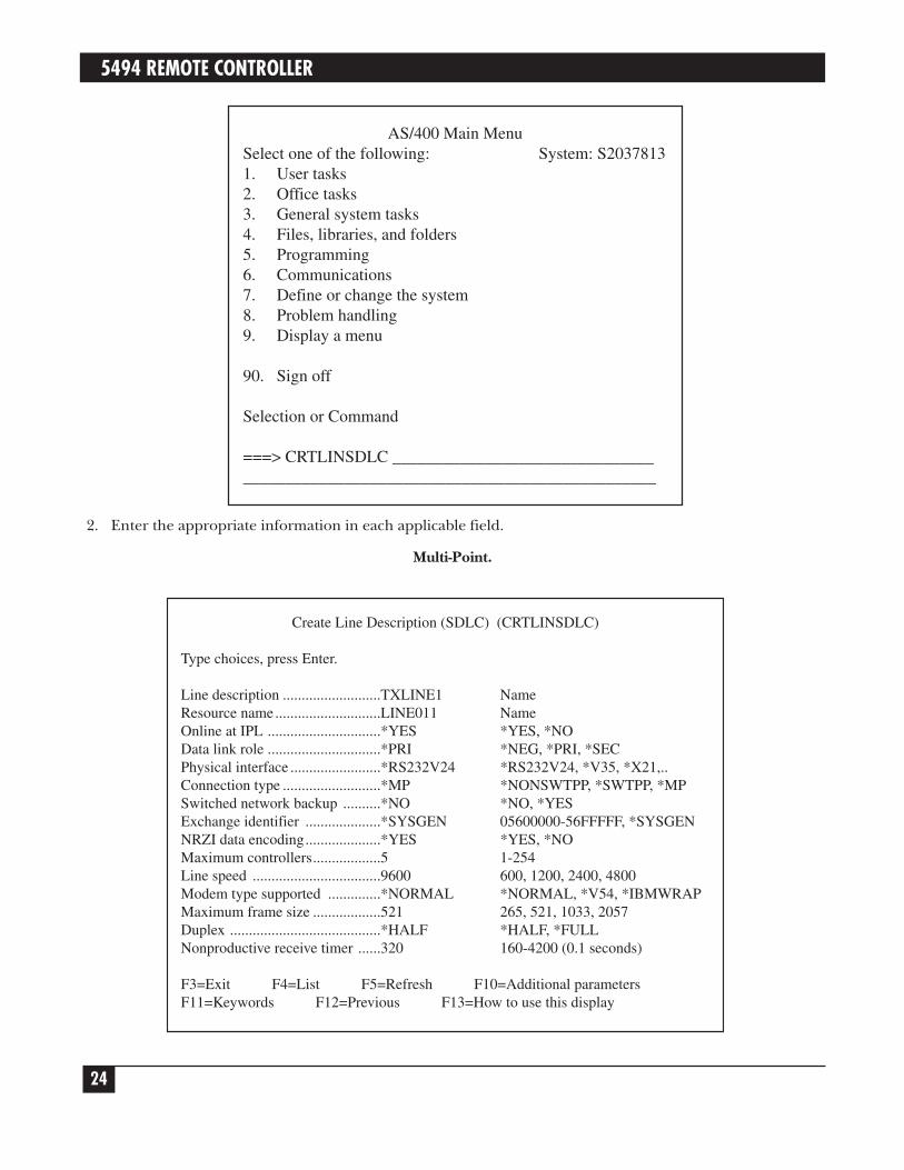
1. Type CRTLINSDLC and press ENTER from the AS/400 Main Menu.
The Create Line Description (SDLC) prompt menu will appear as shown below. Not all lines will bedisplayed at once. As you fill in the options and press ENTER, additional options will be displayed.
In the example at the top of the next page, a nonswitched, multi-point line with a line speed of 9600 bps isdefined.
5494 REMOTE CONTROLLER
24
2. Enter the appropriate information in each applicable field.
Multi-Point.
Create Line Description (SDLC) (CRTLINSDLC)
Type choices, press Enter.
Line description ..........................TXLINE1 NameResource name............................LINE011 NameOnline at IPL ..............................*YES *YES, *NOData link role ..............................*PRI *NEG, *PRI, *SECPhysical interface ........................*RS232V24 *RS232V24, *V35, *X21,..Connection type ..........................*MP *NONSWTPP, *SWTPP, *MPSwitched network backup ..........*NO *NO, *YESExchange identifier ....................*SYSGEN 05600000-56FFFFF, *SYSGENNRZI data encoding....................*YES *YES, *NOMaximum controllers..................5 1-254Line speed ..................................9600 600, 1200, 2400, 4800Modem type supported ..............*NORMAL *NORMAL, *V54, *IBMWRAPMaximum frame size ..................521 265, 521, 1033, 2057Duplex ........................................*HALF *HALF, *FULLNonproductive receive timer ......320 160-4200 (0.1 seconds)
F3=Exit F4=List F5=Refresh F10=Additional parametersF11=Keywords F12=Previous F13=How to use this display
AS/400 Main MenuSelect one of the following: System: S20378131. User tasks2. Office tasks3. General system tasks4. Files, libraries, and folders5. Programming6. Communications7. Define or change the system8. Problem handling9. Display a menu
90. Sign off
Selection or Command
===> CRTLINSDLC ________________________________________________________________________________
CHAPTER 2: Host Configuration
25
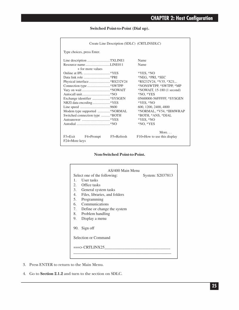
Switched Point-to-Point (Dial up).
Non-Switched Point-to-Point.
3. Press ENTER to return to the Main Menu.
4. Go to Section 2.1.2 and turn to the section on SDLC.
AS/400 Main MenuSelect one of the following: System: S20378131. User tasks2. Office tasks3. General system tasks4. Files, libraries, and folders5. Programming6. Communications7. Define or change the system8. Problem handling9. Display a menu
90. Sign off
Selection or Command
===> CRTLINX25__________________________________________________________________________________
Create Line Description (SDLC) (CRTLINSDLC)
Type choices, press Enter.
Line description ..........................TXLINE1 NameResource name............................LINE011 Name
+ for more valuesOnline at IPL ..............................*YES *YES, *NOData link role ..............................*PRI *NEG, *PRI, *SECPhysical interface ........................*RS232V24 *RS232V24, *V35, *X21,..Connection type ..........................*SWTPP *NONSWTPP, *SWTPP, *MPVary on wait ................................*NOWAIT *NOWAIT, 15-180 (1 second)Autocall unit................................*NO *NO, *YESExchange identifier ....................*SYSGEN 05600000-56FFFFF, *SYSGENNRZI data encoding....................*YES *YES, *NOLine speed ..................................9600 600, 1200, 2400, 4800Modem type supported ..............*NORMAL *NORMAL, *V54, *IBMWRAPSwitched connection type ..........*BOTH *BOTH, *ANS, *DIALAutoanswer ................................*YES *YES, *NOAutodial ......................................*NO *NO, *YES
More. . .F3=Exit F4=Prompt F5=Refresh F10=How to use this displayF24=More keys

5494 REMOTE CONTROLLER
26
Ethernet (upstream)
To define an AS/400 connection to the Remote Controller through an Ethernet network:
1. Type CTRLINETH and press ENTER from the AS/400 Main Menu.
The Create Line Description (Ethernet) prompt menu will appear as shown below. Not all lines will bedisplayed at once. As you fill in the options and press ENTER, additional options will be displayed.
The following is an example of an Ethernet Line description.
2. Enter the appropriate information in each applicable field.
3. Press ENTER to return to the Main Menu.
4. Go to Section 2.1.2 and turn to the section on Ethernet (upstream).
Create Line Description (Ethernet) (CRTLINETH)
Type choices, press Enter.
Line description ..........................ETLINE NameResource name............................CMN08 Name, *NWIDOnline at IPL ..............................*YES *YES, *NOVary on wait ................................*NOWAIT *NOWAIT, 15-180 (1 second)Attached nonswitched NWI........*NONE Name, *NONEDLC identifier ............................*NONE 1-1018, *NONELocal adapter address..................02000000A400* 020000000000-FEFFFFFFFFFF . .Exchange identifier ....................*SYSGEN 05600000-56FFFFF,Ethernet standard ........................*ALL *ETHV2, *IEEE8023, *ALLSSAP list:Source service access point:........*SYSGEN 02-FE, *SYSGENSSAP maximum frame . . . . . . .. *MAXFRAME, 265-1496, 265 . . .SSAP type . . . . . . . . . . . . . . . . .. *CALC, *NONSNA, *SNA
+ for more valuesText "description" ......................*BLANK
BottomF3=Exit F4=Prompt F5=Refresh F10=Additional parametersF12=Cancel F13=How to use this display F24=More keys
*May use internal system I.D. card value
AS/400 Main MenuSelect one of the following: System: S20378131. User tasks2. Office tasks3. General system tasks4. Files, libraries, and folders5. Programming6. Communications7. Define or change the system8. Problem handling9. Display a menu
90. Sign off
Selection or Command
===> CRTLINETH__________________________________________________________________________________

CHAPTER 2: Host Configuration
27
Token-Ring (upstream)
To define an AS/400 connection to the Remote Controller through a Token-Ring network:
1. Type CRTLINTRN and press ENTER from the AS/400 Main Menu.
The Create Line Description (Token-Ring) prompt menu will appear as shown below. Not all lines will bedisplayed at once. As you fill in the options and press ENTER, additional options will be displayed.
The following is an example of a Token-Ring Line description.
Create Line Description (Token-Ring) (CRTLINTRN)
Type choices, press Enter.
Line description ..........................TRLINE NameResource name............................CMN08 NameOnline at IPL ..............................*YES *YES, *NOVary on wait ................................*NOWAIT *NOWAIT, 15-180 (1 second)Maximum controllers..................40 1-256Attached nonswitched NWI........*NONE Name, *NONEDLC identifier ............................*NONE 1-1018, *NONELine speed ..................................4M 4M, 16M, *NWIMaximum frame size ..................16393 265-16393, 265, 521, 1033 . . .Local adapter address..................40000000A400* 400000000000-7FFFFFFFFFFF .Exchange identifier ....................*SYSGEN 05600000-56FFFFF, *SYSGENSSAP list:Source service access point:........*SYSGEN 02-FE, *SYSGENSSAP maximum frame . . . . . . .. *MAXFRAME, 265-16393SSAP type . . . . . . . . . . . . . . . . .. *CALC, *NONSNA, *SNA
+ for more values
More . . .F3=Exit F4=Prompt F5=Refresh F10=Additional parametersF12=Cancel F13=How to use this display F24=More keys
*May use internal system I.D. card value
AS/400 Main MenuSelect one of the following: System: S20378131. User tasks2. Office tasks3. General system tasks4. Files, libraries, and folders5. Programming6. Communications7. Define or change the system8. Problem handling9. Display a menu
90. Sign off
Selection or Command
===> CRTLINTRN__________________________________________________________________________________

5494 REMOTE CONTROLLER
28
2. Enter the appropriate information in each application field.
3. Press ENTER to return to the Main Menu.
4. Go to Section 2.1.2, and turn to the section on Token Ring.
2.1.2 CREATE CONTROL UNIT
The following sections describe the steps to create a control unit description for SDLC communications mode.
SDLC
Take the following steps to define a control unit description for SDLC protocol.
1. Type CRTCTLRWS from the AS/400 Main Menu, and then press F4. The Create Controller Descriptionmenu will appear, as shown below.
Multi Point CTL Description.
Create Ctl Desc (Remote WS) (CRTCTLRWS)
Type choices, press Enter.
Controller description TXCTL1 NameController type 5394 3174, 3274, 5251, 5294 . . .Controller model 1 0, 1, 0001, 2, 0002, 12, 0012Link type *SDLC *IDLC, *LAN, *NONE, . .Online at IPL *YES *YES, *NOSwitched line *NO *NO, *YESSwitched network backup *NO *NO, *YESAttached nonswitched line TXLINE1 NameMaximum frame size *LinktypeExchange identifier *Leave Blank 00100000-FFFFFFFFStation address 01 01-FEText "description" *BLANK

CHAPTER 2: Host Configuration
29
Switched Point-to-Point CTRL Description (Dial up Example).
Non-Switched Point-to-Point CTRL Description.
2. Fill in all applicable data. Not all lines will display at once; the rest will appear as you fill in the options andpress ENTER.
3. Go to Section 2.1.3.
Create Line Description (Remote WS) (CRTCTLRWS)
Type choices, press Enter.
Controller description ................TXCTL1 NameController type ............................5394 3174, 3274, 5251, 5294 . . .Controller model ........................1 0, 1, 0001, 2, 0002, 12, 0012Link type ....................................*SDLC *IDLC, *LAN, *NONE, *SDLC . .Online at IPL ..............................*YES *YES, *NOSwitched connection ..................*NO *NO, *YESShort hold mode..........................*NO *NO, *YESSwitched line list ........................TXLINE1 NameMaximum frame size ..................*LINKTYPE 265-1994, 265, 261, 265 . . .Exchange identifier .................... 00100000-FFFFFFFFStation address ............................AA *01-FEText "description" ......................BLANK
BottomF3=Exit F4=Prompt F5=Refresh F10=Additional parameters
Create Line Description (Remote WS) (CRTCTLRWS)
Type choices, press Enter.
Controller description ................TXCTL1 NameController type ............................5394 3174, 3274, 5251, 5294 . . .Controller model ........................1 0, 1, 0001, 2, 0002, 12, 0012Link type ....................................*SDLC *IDLC, *LAN, *NONE, *SDLC . .Online at IPL ..............................*YES *YES, *NOSwitched connection ..................*YES *YES, *NOShort hold mode..........................*NO *YES, *NOSwitched line list ........................TXLINE1 Name
+ for more valuesMaximum frame size ..................*LINKTYPE 265-1994, 265, 261, 265 . . .Exchange identifier ....................05F000AA 00100000-FFFFFFFFInitial connection ........................*DIAL *DIAL, *ANSDial initiation ..............................*LINKTYPE *LINKTYPE, *IMMED, *DELAYConnection number ....................'555-1212'Station address ............................AA 01-FE
More . . .F3=Exit F4=Prompt F5=Refresh F10=Additional parametersF12=Cancel F13=How to use this display F24=More keys

5494 REMOTE CONTROLLER
30
Ethernet (Upstream)
Take these steps to define a control-unit description for an upstream Ethernet configuration.
1. Type CRTCTLAPPC from the AS/400 main menu, then press F4. The Create Controller Description(APPC) menu will appear.
2. Fill in applicable data. All lines will not display at once, but will appear as you fill in the options and pressENTER.
Create Ctl Desc (APPC) (CRTCTLAPPC)
Type choices, press Enter.
Autodelete device 1440 1-10000, *NOUser-defined 1 *LIND 0-255, *LINDUser-defined 2 *LIND 0-255, *LINDUser-defined 3 *LIND 0-255, *LINDText description LAN, Token-Ring #01
BottomF3=Exit F4=Prompt F5=Refresh F10=Additional parametersF12=Cancel F13=How to use this display F24=More keys
Create Ctl Desc (APPC) (CRTCTLAPPC)
Type choices, press Enter.
Controller description LANTR01 NameLink type *LAN *FAX, *FR, *IDLC, *LAN . .Online at IPL *YES *YES, *NOAPPN-capable *YES *YES, *NOSwitched line list Name
+ for more valuesMaximum frame size *LINKTYPE 265-16393, 256, 265, 512 . . . Remote network identifier APPN Name, *NETATR, *NONE, *ANYRemote control point *ANY Name, *ANYExchange identifier 00100000-FFFFFFFFInitial connection *ANS *DIAL, *ANSDial initiation *LINKTYPE (LINKTYPE, *IMMED, *DELAY)LAN remote adapter address 02001881000 000000000001-FFFFFFFFFFFFAPPN CP session support *YES *YES, *NOAPPN node type *ENDNODE *ENDNODE, *LENNODE . . .APPN transmission group number 1 1-20, *CALC
More . . .F3=Exit F4=Prompt F5=Refresh F10=Additional parametersF12=Cancel F13=How to use this display F24=More keys

CHAPTER 2: Host Configuration
31
3a. If the Remote Controller is configured to emulate more than one IBM remote controller, a configurationlist must be created. Type in CRTCFGL on the AS/400 command line and press ENTER. Select list type“*APPNRMT”.
3b. Each emulated Remote Controller must be added to the newly created configuration list. TypeADDCFGLE on the AS/400 command line and press ENTER.
NOTEThe remote location name and remote control point must match each emulatedcontroller.
4. Go to Chapter 3.
Token-Ring (Upstream)
Take these steps to define a control unit description for an upstream Token-Ring configuration.
1. Type CRTCTLAPPC from the AS/400 Main Menu, then press F4. The Create Controller Description(APPC) menu will appear.
2. Fill in applicable data. Not all lines will display at once; the rest will appear as you fill in the options andpress ENTER.
Create Ctl Desc (APPC) (CRTCTLAPPC)
Type choices, press Enter.
Controller description LANTR01 NameLink type *LAN *FAX, *FR, *IDLC, *LAN . .Online at IPL *YES *YES, *NOAPPN-capable *YES *YES, *NOSwitched line list Name
+ for more valuesMaximum frame size *LINKTYPE 265-16393, 256, 265, 512 . . . Remote network identifier APPN Name, *NETATR, *NONE, *ANYRemote control point *ANY Name, *ANYExchange identifier 00100000-FFFFFFFFInitial connection *ANS *DIAL, *ANSDial initiation *LINKTYPE (LINKTYPE, *IMMED, *DELAY)LAN remote adapter address 400018810000 000000000001-FFFFFFFFFFFFAPPN CP session support *YES *YES, *NOAPPN node type *ENDNODE *ENDNODE, *LENNODE . . .APPN transmission group number 1 1-20, *CALC
More . . .F3=Exit F4=Prompt F5=Refresh F10=Additional parametersF12=Cancel F13=How to use this display F24=More keys

5494 REMOTE CONTROLLER
32
3a. If the Remote Controller is configured to emulate more than one IBM remote controller, a configurationlist must be created. Type in CRTCFGL on the AS/400 command line and press ENTER. Select list type“*APPNRMT”.
3b. Each emulated Remote Controller must be added to the newly created configuration list. TypeADDCFGLE on the AS/400 command line and press ENTER.
NOTEThe remote location name and remote control point must match fields 12 and 13 foreach card or pair of cards.
Create Configuration List (CRTCFGL)
Type choices, press Enter.
Configuration list type *APPNRMT *APPNCL, *APPNRMT
BottomF3=Exit F4=Prompt F5=Refresh F10=Additional parametersF12=Cancel F13=How to use this display F24=More keys
Create Ctl Desc (APPC) (CRTCTLAPPC)
Type choices, press Enter.
Autodelete device 1440 1-10000, *NOUser-defined 1 *LIND 0-255, *LINDUser-defined 2 *LIND 0-255, *LINDUser-defined 3 *LIND 0-255, *LINDText description LAN, Token-Ring #01
BottomF3=Exit F4=Prompt F5=Refresh F10=Additional parametersF12=Cancel F13=How to use this display F24=More keys

CHAPTER 2: Host Configuration
33
4. Go to Chapter 3.
LAN Gateway/SNA LU6.2-PU2.1 Node
Take these steps to define a control unit description for a Token-Ring or Ethernet Gateway configuration andan APPN Network or SNA Subarea Network.
1. Type CRTCTLAPPC from the AS/400 Main Menu, then press F4. The Create Controller Description(APPC) menu will appear:
Add Configuration List Entries (ADDCFGLE)
Type choices, press Enter.
Configuration list type *APPNRMT *APPNLC, *APPNRMT . . .APPN remote location entry:
Remote location name SLC01 Name, generic*, *ANYRemote network identifier *NETATR Name, *NETATR, *NONELocal location name *NETATR Name, *NETATRRemote control point TR5494 Name, *NONEControl point net ID *NETATR Name, *NETATR, *NONELocation password *NONESecure location *NO *YES, *NOSingle session *NO *YES, *NOLocally controlled session *NO *YES, *NOPre-established session *NO *YES, *NOEntry "description" *BLANKNumber of conversations 10 1-512
+ for more values
BottomF3=Exit F4=Prompt F5=Refresh F10=Additional parametersF12=Cancel F13=How to use this display F24=More keys

5494 REMOTE CONTROLLER
34
2. Fill in applicable data. Not all lines will not display at once; the rest will appear as you fill in the options andpress ENTER.
3a. If the Remote Controller is configured to emulate more than one IBM remote controller, a configurationlist must be created. Type CRTCFGL on the AS/400 command line and press ENTER. Select list type“APPNRMT”.
Create Ctl Desc (APPC) (CRTCTLAPPC)
Type choices, press Enter.
Autodelete device 1440 1-10000, *NOUser-defined 1 *LIND 0-255, *LINDUser-defined 2 *LIND 0-255, *LINDUser-defined 3 *LIND 0-255, *LINDText description LAN, Token-Ring #01
BottomF3=Exit F4=Prompt F5=Refresh F10=Additional parametersF12=Cancel F13=How to use this display F24=More keys
Create Ctl Desc (APPC) (CRTCTLAPPC)
Type choices, press Enter.
Controller description LANTR01 NameLink type *SDLC *IDLC, *LAN, *LOCAL, *SDLC . .Online at IPL *YES *YES, *NOSwitched connection *NO *NO, *YESSwitched network backup *NO *NO, *YESAPPN-capable *YES *YES, *NOAttached nonswitched line TXLINE1 NameMaximum frame size 521 265-16393, 256, 265, 512 . . . Remote network identifier APPN Name, *NETATR, *NONE, *ANYRemote control point *ANY Name, *ANYExchange identifier 00100000-FFFFFFFFData link role *NEG *NET, *PRI, *SECStation address 01 00-FEAPPN CP session support *YES *YES, *NOAPPN node type *ENDNODE *ENDNODE, *LENNODE . . .APPN transmission group number 1 1-20, *CALC
More . . .F3=Exit F4=Prompt F5=Refresh F10=Additional parametersF12=Cancel F13=How to use this display F24=More keys

CHAPTER 2: Host Configuration
35
3b. Each emulated remote controller must be added to the newly created configuration list. Type ADDCFGLEon the AS/400 command line and press ENTER.
NOTEThe remote location name and remote control point must match fields 12 and 13 foreach card or pair of cards.
4. Go to Chapter 3.
2.1.3 DEFINE ATTACHED DEVICES (TWINAX ATTACHED ONLY)
Take these steps to configure the devices attached to the Remote Controller.
Add Configuration List Entries (ADDCFGLE)
Type choices, press Enter.
Configuration list type *APPNRMT *APPNLC, *APPNRMT . . .APPN remote location entry:
Remote location name SLC01 Name, generic*, *ANYRemote network identifier *NETATR Name, *NETATR, *NONELocal location name *NETATR Name, *NETATR, *NONERemote control point ET5494 Name, *NONE, *NONEControl point net ID *NETATR Name, *NETATR, *NONELocation password *NONESecure location *NO *YES, *NOLocally controlled session *NO *YES, *NOPre-established session *NO *YES, *NOEntry "description" *BLANKNumber of conversations 10 1-512
+ for more values
BottomF3=Exit F4=Prompt F5=Refresh F10=Additional parametersF12=Cancel F13=How to use this display F24=More keys
Create Configuration List (CRTCFGL)
Type choices, press Enter.
Configuration list type *APPNRMT *APPNCL, *APPNRMT
BottomF3=Exit F4=Prompt F5=Refresh F10=Additional parametersF12=Cancel F13=How to use this display F24=More keys

5494 REMOTE CONTROLLER
36
1. From the AS/400 Main Menu, type CRTDEVDSP, and press F4. The Create Device Description menu isdisplayed, as shown below.
2. Fill in all applicable data. As you fill in the fields and press ENTER, more lines and options will bedisplayed.
Use the following table to determine each device’s local location address.
3. Go to Chapter 3.
Address
Port 0 1 2 3 4 5 6
0 00 01 02 03 04 05 06
1 07 08 09 0A 0B 0C 0D
7
6
4
5
3
2
31
2A
1C
23
15
0E
32
2B
1D
24
16
0F
33
2C
1E
25
17
10
34
2D
1F
26
18
11
35
2E
20
27
19
12
36
2F
21
28
1A
13
37
30
22
29
1B
14
Create Device Desc (Display) (CRTDEVDSP)
Type choices, press Enter.
Device description TXIO119701 NameDevice class *RMT *LCL, *RMT, *VRTDevice type 3197 3179, 3180, 3196, 3197Device model D1 *DHCF, 0, 1, 2, 11, A1, A2Local location address 01 00-41Online at IPL *YES *YES, *NOAttached controller TXCTL1 NameDrop line at signoff *NO *YES, *NOCharacter identifierGraphic character set *SYSVAL 1-32767, *SYSVALCode page 1-32767Allow blinking cursor *YES *YES, *NOPrinter NamePrint file QSYSPRT NameLibrary *LIBL Name, *LIBL, *CURLIBMax length of request unit *CALC *CALC, 241, 245, 247, 256
F3=Exit F4=List F5=Refresh F10=Additional parametersF11=Keywords F12=Previous F13=How to use this display

CHAPTER 2: Host Configuration
37
2.2 System/38 ConfigurationThe following configuration instructions are summarized from the manual IBM System/38, Guide to ProgramProducts Installation and Device Configuration (GC21-7775). Refer to that manual for further details.
To correctly define a communications line with remote controller(s) and devices and then establish hostcommunications, you must do the following.
• Create a line description.
• Create a control unit description.
• Define the devices attached to the Remote Controller.
• Create a subsystem (optional).
• Cancel and/or restart the subsystem (optional).
NOTEIt is recommended that you define one subsystem per communications line to preventlocally attached users and users on other lines from being affected by problemsrelated to a specific communications line.
2.2.1 CREATE LINE DESCRIPTION
Take these steps to define a communications line.
1. From the System Operator menu, enter 80 at the option field to retrieve the Command Grouping menu.
2. From the Command Grouping menu, select “Configuration Menu”, option 15.
3. From the Configuration menu, select “Line Description Menu”, option 11.
SYSTEM OPERATOR MENU
Select one of the following:
1. DSPJOBQ (jobq)2. DSPOUTQ (outq)3. SNDMSGtomsq, (type), msg4. CALL program5. Execute command6. SBMJOB (job), (jobd), (cmd)7. STRPRTWTR dev, outq8. DSPWTR (writer)9. SBMDKTJOB dev, label, (loc)10. SBMDBJOB file, (member)11. DSPSBMJOB12. DSPACTJOB (reset)80. DSPMNU (menu)90. SIGNOFF (*NOLIST *LIST)
Option: 80 Parms:Cmd or parm:Log requests: *YES CF3-Command entry CF4-Prompt (5,6 only)CF6-DSPMSG QSYSOPR CF7-DSPSBS F8-DSPSYS

5494 REMOTE CONTROLLER
38
4. Select “Create Line Description”, option 2 on the Line Description menu.
5. From the Create Line Description Prompt menu, enter the selections for the line being defined. Two morescreens will appear after the first one.
If YES is indicated for NRZI decoding, the host is set for NRZI (non-return-to-zero inverted), if NO, NRZ(NONRZI, non-return-to-zero) is selected. This is the SDLC transmission coding option used to keepsynchronization loss between modems to a minimum. Both the host and controller must use the same setupoption. The recommended initial setting is NO (NRZ) if the EIA interface is connected to digitalmodems/DCEs, and YES (NRZI) when the EIA interface is used with analog modems/DCEs.
CREATE LINE DESCRIPTION (CRTLIND) PROMPT
Data terminal ready delay: DTRDLY 1Idle detection time: IDLETIME 38BSC receive timeout timer: RCVTMR 15Nonproductive receive time: NONPRDRCV 2Number of error retries: RETRY 1Online at CPF start (*YES *NO) ONLINE *YESNonswitched control units CTLU
+ for moreBSC switched control units: SWTCTLU
+ for moreStation address: STNADRExchange identifier in hex: EXCHID *NONELine code (*EBCDIC *ASCII): CODE *EBCDICRemote job entry (*NO *YES): RJE *NOBSC switched line disconnect? BSCSWTDSC *YES3270 device emulation? EML3270 *NOX.25 network type: X25NETTYPE 0101X.25 network local address: LCLNETADR *NONEX.25 default packet size: DFTPKTSIZE 128X.25 maximum packet size: MAXPKTSIZE *DFTPKTSIZEX.25 default window size: DFTWDWSIZE 2
CREATE LINE DESCRIPTION (CRTLIND) PROMPT
Enter the following:
Line description name: LIND R TXLINE1OU number of line port: LINNBR R 21Line type: TYPE R *SDLCPConnection type (*SWT *PP *MP): CNN R *PPData rate: RATE R 9600Switched network backup? SWNBKU *NOSpeed select feature? SELECTNRZI decoding (*NO *YES): NONRTNZ *YESS/38 provided clock (*NO *YES): CLOCK *NOAutocall feature (*NO *YES): AUTOCALL *NOAutoanswer feature (*NO *YES): AUTOANS *NOS/38 answer tone (*NO *YES): ANSTONE *NOPhysical wire connection WIRE
Normal wire type (2 4): 4Backup type, if SWNBKU (2 4)
Data comm equipment group: DCEGRPNon-IBM modem (*NO *YES): OEMMDM *NOSwitched connected type: SWTCNN *BOTHSpeed rate type (*FULL *HALF) RATETYPE *FULLDial mode (*MANUAL *AUTO) DIALMODEAnswer mode (*MANUAL *AUTO): ANSMODE

CHAPTER 2: Host Configuration
39
2.2.2 CREATE CONTROL UNIT DESCRIPTION
Take these steps to create a control unit description.
1. After the Line Description is defined, the Line Description menu will be displayed on your screen. PressCF2 to retrieve the Configuration menu.
2. Select “Control Unit Description Menu,” option 7, from the Configuration menu.
3. From the Control Unit Description menu, select option 2, “Create Control Unit Description.”
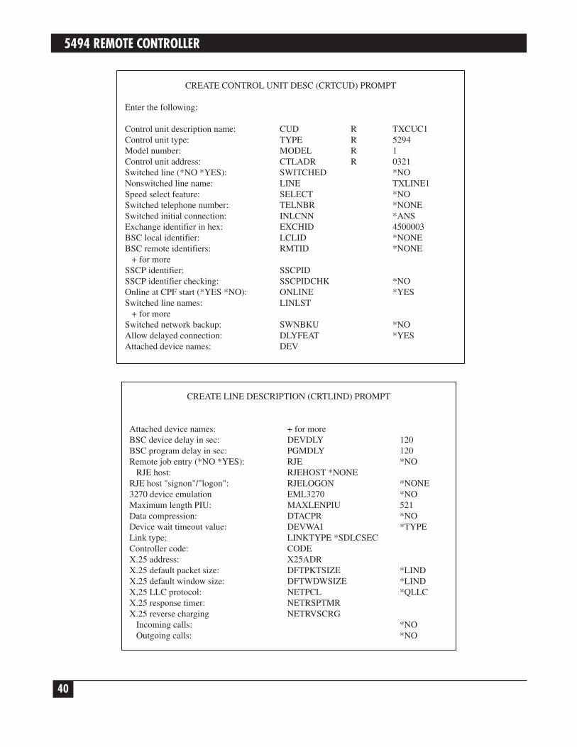
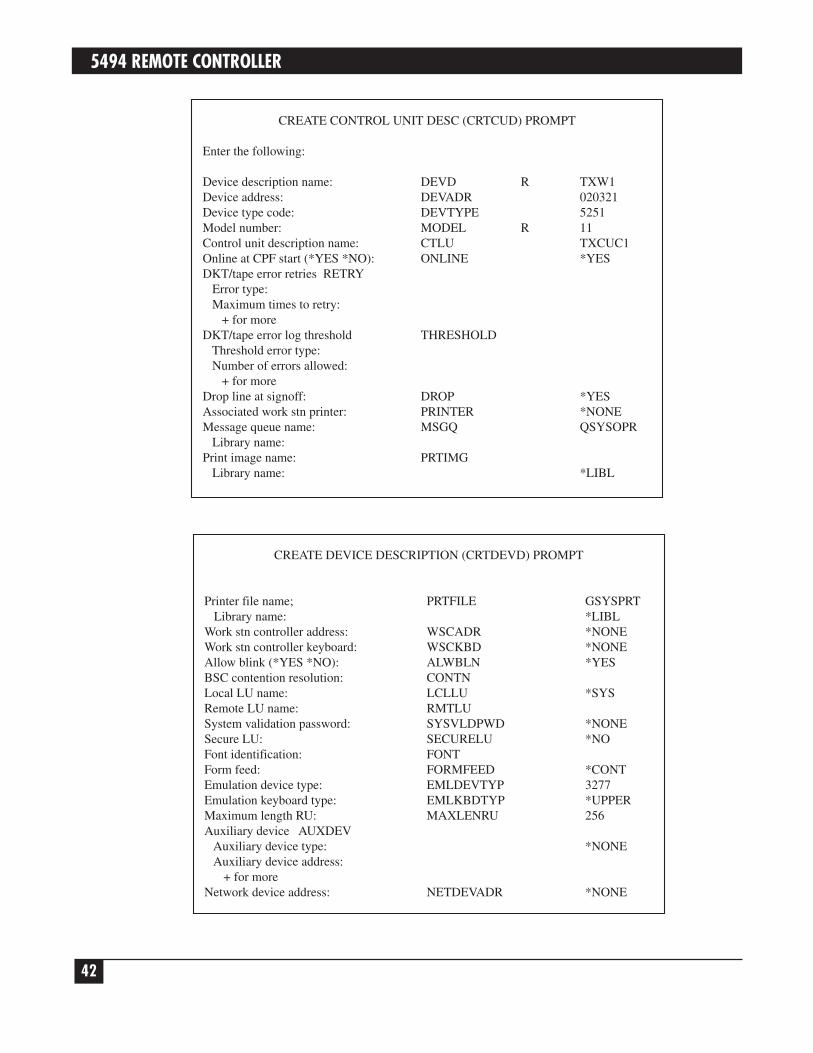
4. From the Create Control Unit Description Prompt menu, enter the selections related to the control unityou are defining. There are two more prompt menus following the first one.
The CTLADR (control unit address) is a four-digit number where the first two digits (03 in the example)are the control unit address in hex and the last two digits (21 in the example) represent the number of theline.
The EXCHID (exchange identifier index) is a required option where “045000” is a fixed value and the lasttwo digits (03 in the example)—represent the controller address in hex.
CREATE CONTROL UNIT DESC (CRTCUD) PROMPT
Enter the following:
Control unit description name: CUD R TXCUC1Control unit type: TYPE R 5294Model number: MODEL R 1Control unit address: CTLADR R 0321Switched line (*NO *YES): SWITCHED *NONonswitched line name: LINE TXLINE1Speed select feature: SELECT *NOSwitched telephone number: TELNBR *NONESwitched initial connection: INLCNN *ANSExchange identifier in hex: EXCHID 4500003BSC local identifier: LCLID *NONEBSC remote identifiers: RMTID *NONE
+ for moreSSCP identifier: SSCPIDSSCP identifier checking: SSCPIDCHK *NOOnline at CPF start (*YES *NO): ONLINE *YESSwitched line names: LINLST
+ for moreSwitched network backup: SWNBKU *NOAllow delayed connection: DLYFEAT *YESAttached device names: DEV
5494 REMOTE CONTROLLER
40
CREATE LINE DESCRIPTION (CRTLIND) PROMPT
Attached device names: + for moreBSC device delay in sec: DEVDLY 120BSC program delay in sec: PGMDLY 120Remote job entry (*NO *YES): RJE *NO
RJE host: RJEHOST *NONERJE host "signon"/"logon": RJELOGON *NONE3270 device emulation EML3270 *NOMaximum length PIU: MAXLENPIU 521Data compression: DTACPR *NODevice wait timeout value: DEVWAI *TYPELink type: LINKTYPE *SDLCSECController code: CODEX.25 address: X25ADRX.25 default packet size: DFTPKTSIZE *LINDX.25 default window size: DFTWDWSIZE *LINDX,25 LLC protocol: NETPCL *QLLCX.25 response timer: NETRSPTMRX.25 reverse charging NETRVSCRG
Incoming calls: *NOOutgoing calls: *NO
CREATE CONTROL UNIT DESC (CRTCUD) PROMPT
Enter the following:
Control unit description name: CUD R TXCUC1Control unit type: TYPE R 5294Model number: MODEL R 1Control unit address: CTLADR R 0321Switched line (*NO *YES): SWITCHED *NONonswitched line name: LINE TXLINE1Speed select feature: SELECT *NOSwitched telephone number: TELNBR *NONESwitched initial connection: INLCNN *ANSExchange identifier in hex: EXCHID 4500003BSC local identifier: LCLID *NONEBSC remote identifiers: RMTID *NONE
+ for moreSSCP identifier: SSCPIDSSCP identifier checking: SSCPIDCHK *NOOnline at CPF start (*YES *NO): ONLINE *YESSwitched line names: LINLST
+ for moreSwitched network backup: SWNBKU *NOAllow delayed connection: DLYFEAT *YESAttached device names: DEV

CHAPTER 2: Host Configuration
41
2.2.3 DEFINE ATTACHED DEVICES
Take the following steps to create device descriptions for the devices attached to the Remote Controller.
1. After the control unit is defined, press CF2 from the Control Unit Description menu to retrieve theConfiguration menu.
2. From the Configuration menu, select “Device Description Menu,” option 8.
3. From the Device Description menu, select “Create Device Description,” option 2.
4. From the Create Device Description Prompt menu, enter the valid values for the device being created. Twomore prompt menus follow the first one (as shown on the next page).
CREATE CONTROL UNIT DESC (CRTCUD) PROMPT
X.25 closed user group ID: NETCUGID *NONEX.25 connection password: NETCNNPWD *NONEX.25 user facilities: NETUSRFCL *NONEPublic authority PUBAUT
(*NORMAL *ALL *NONE): *NORMALText description: TEXT *BLANK
5494 REMOTE CONTROLLER
42
CREATE DEVICE DESCRIPTION (CRTDEVD) PROMPT
Printer file name; PRTFILE GSYSPRTLibrary name: *LIBL
Work stn controller address: WSCADR *NONEWork stn controller keyboard: WSCKBD *NONEAllow blink (*YES *NO): ALWBLN *YESBSC contention resolution: CONTNLocal LU name: LCLLU *SYSRemote LU name: RMTLUSystem validation password: SYSVLDPWD *NONESecure LU: SECURELU *NOFont identification: FONTForm feed: FORMFEED *CONTEmulation device type: EMLDEVTYP 3277Emulation keyboard type: EMLKBDTYP *UPPERMaximum length RU: MAXLENRU 256Auxiliary device AUXDEV
Auxiliary device type: *NONEAuxiliary device address:
+ for moreNetwork device address: NETDEVADR *NONE
CREATE CONTROL UNIT DESC (CRTCUD) PROMPT
Enter the following:
Device description name: DEVD R TXW1Device address: DEVADR 020321Device type code: DEVTYPE 5251Model number: MODEL R 11Control unit description name: CTLU TXCUC1Online at CPF start (*YES *NO): ONLINE *YESDKT/tape error retries RETRY
Error type:Maximum times to retry:
+ for moreDKT/tape error log threshold THRESHOLD
Threshold error type:Number of errors allowed:
+ for moreDrop line at signoff: DROP *YESAssociated work stn printer: PRINTER *NONEMessage queue name: MSGQ QSYSOPR
Library name:Print image name: PRTIMG
Library name: *LIBL

CHAPTER 2: Host Configuration
43
Use the following table to determine each device address.
Address
Port 0 1 2 3 4 5 6
0 00 01 02 03 04 05 06
1 07 08 09 0A 0B 0C 0D
CREATE DEVICE DESCRIPTION (CRTDEVD) PROMPT
Character identifier CHRIDGraphic character set: *SYSVLCode page:
Public authority PUBAUT(*NORMAL *ALL *NONE): *NORMAL
Text description: TEXT *BLANK

5494 REMOTE CONTROLLER
44
2.2.4 CREATE SUBSYSTEM
Take the following steps to create a subsystem on a communications line.
1. From the System Operator menu, enter option 80 to retrieve the Command Grouping menu.
2. From the Command Grouping menu, select option 14, “Work Management Menu.”
3. Select option 5 from the Work Management menu to retrieve the Subsystem Description menu.
4. Select option 2 on the Subsystem Description menu to retrieve the Create Subsystem Description menu.
SYSTEM OPERATOR MENU
Select one of the following:
1. DSPJOBQ (jobq)2. DSPOUTQ (outq)3. SNDMSGtomsq, (type), msg4. CALL program5. Execute command6. SBMJOB (job), (jobd), (cmd)7. STRPRTWTR dev, outq8. DSPWTR (writer)9. SBMDKTJOB dev, label, (loc)10. SBMDBJOB file, (member)11. DSPSBMJOB12. DSPACTJOB (reset)80. DSPMNU (menu)90. SIGNOFF (*NOLIST *LIST)
Option: 80 Parms:Cmd or parm:Log requests: *YES CF3-Command entry CF4-Prompt (5,6 only)CF6-DSPMSG QSYSOPR CF7-DSPSBS F8-DSPSYS

CHAPTER 2: Host Configuration
45
5. Enter the information required for the subsystem you are creating.
NOTEFollow the procedures outlined in Section 2.2.3 to define devices for the subsystem.
2.2.5 CANCEL/RESTART SUBSYSTEM
If a Line/Controller/Device is related to an existing subsystem, you must terminate the subsystem by selectingoption 5 from the System Operator menu, and entering TRMSBS [subsystem name] on the line “Cmd orparm:”.
To start the subsystem (this must be done for a newly created subsystem or for an existing terminatedsubsystem), select option 5, and enter STRSBS TXLINE1 on the line “Cmd or parm:”. In the example,TXLINE1 is the name of the subsystem.
CREATE SUBSYSTEM DESCRIPTION (CRTSBSD) PROMPT
Enter the following:
Subsystem description name: SBSD R TXLINE1Library name: QGPL
Storage pool POOLS RPool identifier (1-10): 1Stg size or *BASE *NOSTG: *BASEActivity level, if stg size:
+ for moreMaximum number of jobs: MAXJOBS P *NOMAXDisplay file name: SGNDSPF *QDSIGNON
Library name:Public authority PUBAUT(*NORMAL *ALL *NONE): *NORMALText description: TEXT *BLANK

5494 REMOTE CONTROLLER
46
2.3 System/36 ConfigurationThe following configuration instructions are summarized from the manual IBM System/36, Changing YourSystem Configuration (SC21-9052). Refer to that manual for further details. Before you begin, make sure youhave security clearance (if security is installed). Print a copy of the existing configuration member forreference.
To correctly define a communications line on a System/36, you must do the following.
• Define and run the SETCOMM procedure.
• Create or change the configuration member.
• Define a communications line.
• Define the remote controller.
• Define the devices attached to the remote controller.
• IPL the system.
SYSTEM OPERATOR MENU
Select one of the following:
1. DSPJOBQ (jobq)2. DSPOUTQ (outq)3. SNDMSGtomsq, (type), msg4. CALL program5. Execute command6. SBMJOB (job), (jobd), (cmd)7. STRPRTWTR dev, outq8. DSPWTR (writer)9. SBMDKTJOB dev, label, (loc)10. SBMDBJOB file, (member)11. DSPSBMJOB12. DSPACTJOB (reset)80. DSPMNU (menu)90. SIGNOFF (*NOLIST *LIST)
Option: 5 Parms:Cmd or parm: STRSBS TXLINE1Log requests: *YES CF3-Command entry CF4-Prompt (5,6 only)CF6-DSPMSG QSYSOPR CF7-DSPSBS F8-DSPSYS

CHAPTER 2: Host Configuration
47
2.3.1 DEFINE SETCOMM PROCEDURE
The SETCOMM procedure sets the communications configuration parameters. On your default menu, enterthe procedure SETCOMM, and assign the values that apply to your configuration (see below).
NOTEIf you have multiple twinax cards installed in the controller, you must specify“Nonswitched Line” when configuring for the Remote Controller.
The SETCOMM procedure options select either NRZI (non-return-to-zero—inverted) or NONRZI (NRZ, non-return-to-zero) SDLC transmission coding options. These options keep synchronization loss between themodems to a minimum. Host and controller must use the same coding option.
A NONRZI selection is recommended for an EIA interface with digital modems/DCEs, and a NRZI selection isrecommended for EIA interfaces with analog modems/DCEs.
NOTEEnabling continuous carrier on a multi-drop line is not recommended. However, thisoption can increase performance if enabled on a point-to-point leased line.
If your SETCOMM procedure has already been run, you may display system communications status by typingD H, then pressing ENTER.
SETCOMM Procedure
Set the communications configuration parametersLine number 1-1- 1Line type SHM, Multcont, Multtrib, Swtch, Nonswtch Nonswtch*Multipoint control Yes, No NoUse system clocking facility Clock, Noclock NoclockNRZI data encoding NRZI, NONRZI NONRZI*Use continuous carrier feature Concar, noconcar Noconcar*Use non-U.S. answer tone Tone NotoneUse autocall separator characters SEP, NOSEPUse autocall end-of-number charactersEON, NOEONPrimary SDLC time-out value 5-80 5Number of primary SDLC error retries1-5 3Modem IBMLPDA, IBMWRAP, NONIBM NONIBMX.25 support X25, NOX25DDSA line speed 2400BPS, 48700BPS, 9600BPS, 56KBPSSecondary SDLC inactivity time-out value 0-20 5IBM Token-Ring Network adapter address override 4000000-7FFFFFFF,R
Cmd3-Previous Menu

5494 REMOTE CONTROLLER
48
2.3.2 CREATE OR CHANGE CONFIGURATION MEMBER
Take the following steps to create or change the configuration member.
1. From the Main System/36 Help menu, enter the CNFIGSSP command to start the System/36 workstationconfiguration.
The CNFIGSSP Main menu will appear.
NOTEYou can also select the CNFIGSSP Main menu by selecting option 7 from the MainSystem/36 Help menu. The DEFSYS menu will be displayed. Select option 2 from theDEFSYS menu to retrieve the CNFIGSSP Main Menu.
3.0 CONFIGURATION MEMBER DEFINITION
Select one of the following:
1. Change an existing configuration member2. Create a new configuration member3. Delete a configuration member
Option:.......................................................................................................1
Member name:...........................................................................................SYSCNFIG
Library name: ............................................................................................#CNFGLIB
Cmd3-Previous Menu
1.0 CNFIGSSP - Main MenuSelect one of the following:1. How to use CNFIGSSP2. Create, change, or delete a configuration member3. Review a configuration4. Print a configuration10. Configuration support aids12. Apply change to the master configuration record13. Rebuild the master configuration record (update to next release)14. End CNFIGSSP
Option: 2
Cmd3-Previous MenuHelp text is available throughout the CNFIGSSPprocedure by pressing the help key

CHAPTER 2: Host Configuration
49
2. From the CNFIGSSP—Main menu, select option 2, “Create, change, or delete a configuration member.”Options 12 and 13 will not appear if you don’t have proper security clearance.
3. From menu 3.0, Configuration Member Definition, select option 1, “Change an existing configurationmember,” and press ENTER. The member name and library name may be different depending on theconfiguration of your system.
4. From menu 6.0, Configuration Member Description, press ENTER. The information on the screen willvary depending on the configuration of your system.
6.0 CONFIGURATION MEMBER DESCRIPTION SYSCNFIG
1. Describe the configuration member (up to 60 characters):MASTER CONFIGURATION
2. Specify main storage size in K-bytes 0128-7168 1024
3. Specify disk storage size in M-bytes 0030-1432 0200
Cmd3-Previous Menu
3.0 CONFIGURATION MEMBER DEFINITION
Select one of the following:
1. Change an existing configuration member2. Create a new configuration member3. Delete a configuration member
Option:.......................................................................................................1
Member name:...........................................................................................SYSCNFIG
Library name: ............................................................................................#CNFGLIB
Cmd3-Previous Menu

5494 REMOTE CONTROLLER
50
5. From menu 5.0, Configuration Member menu, select option 1, “Work with display stations and printers.”
6. From menu 27.0, Configuration—Display Station and Printer menu, select option 2, “Add or deleteremote line characteristics.”
27.0 CONFIGURATION - DISPLAY STATION AND PRINTER MENU SYSCNFIG
Select one of the following:
1. Add or delete local display stations and printers2. Add or delete remote line characteristics3. Add or delete remote controllers, display stations, and printers4. Assign default printers to display stations5. Assign display station control (subconsoles) for printers6. Change display station or printer workstation IDs7. Change display station or printer characteristics8. Select the system printer9. Add remote service device definition10. Delete remote service device definition11. Return to previous menu
Option: 2
5.0 CONFIGURATION MEMBER MENU SYSCNFIG
Select one of the following:
1. Work with display stations and printers
2. Add or delete program products, optional SSP, and features
3. Define base SSP values
4. Specify sizes for disk VTOC, history file, and task work area
If no more changes are to be made to your configuration member select thefollowing option:
5. Save configuration member and return to main menu for CNFIGSSP
Option: 1
Cmd3-Previous menu Cmd19-Cancel

CHAPTER 2: Host Configuration
51
2.3.3 DEFINE COMMUNICATIONS LINE
Take the following steps to define a communications line.
1. Retrieve menu 10.0, CNFIGSSP Communications Line Definition.
2. From menu 10.0, CNFIGSSP Communications Line Definition for Remote Workstations, type in thenumber of the line that is being defined.
3. Enter the selections for the line being defined. The example shows a nonswitched (point-to-point or multi-point) line defined as line number 1.
4. Continue to define each line in the same manner.
10.0 CNFIGSSP - COMMUNICATIONS LINE DEFINITION SYSCNFIGFOR REMOTE WORK STATIONS
The following lines have been defined:
1. Which line is being defined? .....................1-10 12. What type of line is it?............................... 1
1 - Nonswitched 2 - Switched manual call3 - Switched autoanswer 4 - Switched manual answer5 - X.21 short-hold mode 6 - IBM Token-Ring Network
3. Automatic reconnect for the line?..............Y,N N4. If line is X.25, enter X.25 member name . . .
Cmd3-Previous menu Cmd9-Drop line Cmd19-Cancel
10.0 CNFIGSSP - COMMUNICATIONS LINE DEFINITION SYSCNFIGFOR REMOTE WORK STATIONS
The following lines have been defined:
1. Which line is being defined? .....................1-10 1
Cmd3-Previous menu Cmd9-Drop line Cmd19-Cancel

5494 REMOTE CONTROLLER
52
2.3.4 DEFINE REMOTE CONTROLLER AND ATTACHED DEVICES
Take the following steps to define a remote controller and its attached devices.
1. After you have configured the line(s), press ENTER or CMD3 until you reach screen 27.0, Configuration—Display Station and Printer menu.
2. Select option 3, “Add or delete remote controllers, display stations, and printers.”
13.0 CNFIGSSP - REMOTE CONTROLLER DEFINITION SYSCNFIG
EDIT Controller: C01
1. Describe the remote controller............................Remote Controller2. Controller type ....................................................2
1. 5251 Model 12 2. 5294 3. 32743. Controller station address ........01-FD 014. Communications line................1-10 15. For a switched line, optionally specify 1 to 3 alternative lines.
Cmd2-Scan Cmd3-Previous menu Cmd5-Add controllerCmd6-Restart Cmd9-Delete remote controller
27.0 CONFIGURATION - DISPLAY STATION AND PRINTER MENU SYSCNFIG
Select one of the following:
1. Add or delete local display stations and printers2. Add or delete remote line characteristics3. Add or delete remote controllers, display stations, and printers4. Assign default printers to display stations5. Assign display station control (subconsoles) for printers6. Change display station or printer workstation IDs7. Change display station or printer characteristics8. Select the system printer9. Add remote service device definition10. Delete remote service device definition11. Return to previous menu
Option: 3
Cmd3-Previous Menu Cmd19-Cancel

CHAPTER 2: Host Configuration
53
3. From menu 13.0, CNFIGSSP—Remote Controller Definition, enter the selections for the control unitbeing defined. The example defines a controller on line number 1. Your selections might be differentdepending on the line you have defined.
4. From menu 12.0, CNFIGSSP—Workstation Definition, assign the appropriate device code to eachworkstation address. Only port 0 and 1 can be used (the Remote Controller has two ports for each 5294emulation).
5. Continue to define the next control unit or end the session with CMD 3.
2.3.5 IPL THE SYSTEM
When you have finished defining the communications line(s) and/or the controller(s), take the followingsteps.
1. From menu 27.0, Configuration Display Station and Printer menu, select options 4, 5, 6, and 7 asapplicable for your configuration.
2. From menu 5.0, Configuration Member menu, select option 5, “Save configuration member,” and returnto Menu 1.0, the CNFIGSSP—Main Menu.
3. To apply the changes, you must have a dedicated system (all devices signed off and no active spool jobs).Select option 12 on the CNFIGSSP—Main Menu to apply the changes permanently. This will IPL yoursystem.
12.0 CNFIGSSP - WORKSTATION DEFINITION REMOTE SYSCNFIG
Specify the arrangement of your display stations and printers. The positions correspond to the workstationaddress.
Displays: 00. Single Color display station
0 1 2 3 4 5 6 Workstation address01 10 0—P---------------------01 PC 10 10 1—0
2—R3—T 5294
---------------------
Cmd3-Previous menu Cmd5-Display device codes Cmd19-Cancel

5494 REMOTE CONTROLLER
54
3. Controller InstallationThe front of the Remote Controller has a power-on switch, a test switch, status indicators and a diskette drive.The rear panel has cable and power connections, card installation slots, and status indicators. Thecommunications interface card (MPIC Card) is factory-installed.
The host must have appropriate communications software installed—for example, Remote WorkstationSupport on an IBM 5360.
The software which runs on the Controller depends on how it is connected to the host. One of the followingdiskettes will come with your controller.
Remote Controller system diskettes:5494XXADSK01XXX SDLC without LAN5494XXADSK02XXX SDLC with LAN
Note: “XXX” represents the version number.
3.1 Site ConsiderationsPut the Remote Controller on a desk or table. Make sure the controller has at least six inches of clearance (airspace) on the top, sides, and back for cooling. You should also remember that you will need access to thecontroller to add devices, cards, cables, and new software. The guidelines below will help you choose the propersite for your new controller.
Place the Remote Controller away from electromagnetic sources such as electric motors, transformers, andhigh-voltage power lines. Keep the controller away from other electronic devices (their power supplies maycause interference), high humidity, dust, and water.
If you’re unfamiliar with how site selection can affect the proper operation of your controller, review thefollowing site cabling and electrical considerations.
3.1.1 TWINAX CABLE
Workstations are connected to the Remote Controller and to each other by twinax cable. This cable is ashielded, two-conductor cable that can be used indoors or outdoors with lightning protectors on both ends.
NOTETo avoid interference, do not install twinax cables within 1 foot (0.3 m) of powerequipment or power lines.
Installation of cabling should include tests to ensure that there are no faults, no high-resistance connections,and no circuit imbalances. Tests should ensure that the following common cable problems are eliminated.
• No open circuits in individual conductors or shields
• No short circuits between conductors of the same pair

CHAPTER 3: Controller Installation
55
• No grounds on individual conductors, either between a conductor and a shield, or between a conductorand a grounded object
• No reversed polarities
The twinax cabling must comply with standard twinax requirements, such as no extended “T’s”, no more than11 “T” connections per cable, and correct cable-through and termination. Refer to Appendix A, RelatedDocumentation, for manuals that are useful in determining twinax cabling requirements.
3.1.2 TWISTED PAIR
Each twinax card has a jumper (location J2) that should be removed from one of the jumper pins if twisted-pair/balun cabling systems are used and devices do not establish communication with the host. This willcustomize the installation of the remote controller to meet the requirements in such installations.
NOTENon-twisted-pair cable (also referred to as “silver satin”) is not within specificationand cannot be used. If this is used, your connection may not work at all, or you mayencounter intermittent problems.
Category 5 cable (Black Box part number EYN737A) is the recommended cable type.
3.1.3 COMMUNICATIONS CABLE
X.21 communications cable (Black Box part number EHN060-0020)RS-232 communications cable (Black Box part number EHN061-0020)V.35 communications cable (Black Box part number EHN062-0020)
The appropriate interface communications cable is used to connect the Remote Controller to the modem orDCE and should correspond to your host system’s communications protocol (SDLC).
One of the following 20-foot communications cables is supplied with the Remote Controller (as specified attime of order).
If your remote controller is set up for SNA/SDLC communications and you wish to connect it locally, one ofthe optional cables below is required. These cables are available from Black Box.
X.21 cable (Black Box part number EHN063-0020)RS-232 cable (Black Box part number EHN064-0020)V.35 cable (Black Box part number EHN065-0020)
3.1.4 ELECTRICAL REQUIREMENTS
Standard voltages of 115 VAC at 50 Hz or 230 VAC at 60 Hz are preset at the factory. The voltage is marked onthe power-supply module in the unit. See Specifications in Chapter 1 for detailed information on powerrequirements.
The Remote Controller has a three-wire power cord that includes an equipment ground wire. Be sure thatcorrectly grounded receptacles are located within reach of the power cord and away from traffic areas.

5494 REMOTE CONTROLLER
56
3.2 SetupTo set up the Remote Controller, you will need to do the following. (Also refer to the Remote ControllerInstallation Guide).
• Install any additional twinax cards (if applicable).
• Install any LAN cards (if applicable).
If neither of the above applies, continue to Section 3.6.
3.3 Configure Interface CardThe following four interface cards for host communications are available with the Remote Controller.
8-Port Device Twinax Card (PC394C)Token Ring Card (PC395C)Ethernet Card (PC396C)14-Device Twinax Card (PC397C)
3.3.1 MPIC
The MPIC (Multipurpose Communications Interface Card) is identified through the DB44 connector (44-pinfemale connector) with 5 LEDs directly under the connector. It is used for SNA/SDLC communications.
The MPIC is already installed in your Remote Controller. You can attach the Remote Controller directly to thehost system for local applications (DCE mode) with a special modem-eliminator communications cable. Note:The MPIC card is required.
3.3.2 REMOTE (DTE) MODE
In remote mode, the MPIC’s port functions as a DTE and should be connected to the host through modems orCSU/DSUs.
3.3.3 LOCAL (DCE) MODE
In local (DCE) mode, the MPIC’s port functions as a DCE interface. The controller can be connected directlyto a local host. You must use a special modem-eliminator cable to connect the Remote Controller to the host tooperate in local mode.
If set up for local attachment, make sure the baud rate is set to the desired value when configuring the RemoteController software. The baud rate is set in field 10 of the configuration screen. (See Section 3.13.)
3.4 Install Twinax CardFollow the instructions below to install twinax cards.
NOTELike most circuit boards, the twinax cards can be damaged by static-electricitydischarges. Take static precautions, such as touching a grounded surface or wearinga wrist strap connected to a grounded surface, during installation of the twinaxcard(s).

CHAPTER 3: Controller Installation
57
1. Turn off power to the controller.
2. Remove the single screw at the top center of the back cover.
3. Locate the first or next available slot in the controller (as marked 1 through 6), and remove the slot coverbracket. Save the screw.
4. Install the twinax card, making sure to align the card in the card brackets at the front and rear of thecontroller. Firmly seat the card until the slot bracket on the twinax card is flush against the controllerchassis and the holes align. Fasten with the screw you removed in the previous step.
5. The twinax card’s DIP switches must be set for the slot number in which the card is installed, as shown inthe table below. Figure 3-4 shows how the DIP switches are set.
Slot Switch NumberNumber 1 2 3 4 5 6 7 8Slot 1 Off On Off On On Off Off OffSlot 2 Off On Off On Off Off Off OffSlot 3 Off Off On On On Off Off OffSlot 4 Off Off On On Off Off Off OffSlot 5 Off Off On Off On Off Off OffSlot 6 Off Off On Off Off Off Off Off
6. After setting the DIP switches, reassemble the controller.
3.5 Connect Communications CableThe communications cable is used to connect the Remote Controller to the modem or DCE and shouldcorrespond to your system’s communications protocol (SDLC).
Take the following steps to connect the communications cable to the Remote Controller.
1. Turn off power to the Remote Controller.
2. Connect one end of the communications cable to the modem or host (for local communications).
1 2 3 4 5 6 7 8Off
On

5494 REMOTE CONTROLLER
58
Ensure the modem or DSU/CSU is setup according to the manufacturer’s instructions. In order tocommunicate, the Remote Controller requires that the modem respond to an RTS signal by turning on theCTS signal.
Some modems may require a half-duplex setting (sometimes referred to as hdx or 2-wire) before themodem will provide the CTS response. The Remote Controller supports modems operating in full-duplexmode if appropriate CTS response is provided.
NOTEIf the strappings on the modem for Ready to Send and Clear to Send are not setproperly, the Remote Controller may not operate.
3. Connect the other end of the communications cable to the appropriate communications port on theinterface card.
For SNA/SDLC communications, connect the cable to the MPIC interface (5 LEDs under the DB44connector) installed in the MPIC slot.
4. Tighten the attachment screws by hand to secure the connections.
5. If a LAN configuration is used, the cable between the remote controller and the LAN must be attached andproperly terminated prior to powering on the controller. If this is not done, the remote controller will notoperate.
3.6 Software Configuration of the Remote ControllerBefore the Remote Controller can be used in normal operation, a software configuration procedure must beperformed. This procedure provides the controller software with parameters it needs in order to communicatesuccessfully with the host computer. Configuration information is stored in a data file that resides on thecontroller’s software diskette.
Configuration can be performed either “on-line” or “standalone”. On-line configuration is done using thecontroller itself; the software diskette is loaded into the controller, and configuration parameters are enteredusing a twinax display attached to the controller. Standalone configuration is performed using a PC with thesoftware diskette loaded into a 3.5" drive on the computer. Most details of the configuration process are verysimilar in the two cases; differences will be described later on.
Before performing the software configuration, you may wish to make a backup copy of your Remote Controllersoftware diskette. The backup needs to be made by using the DISKCOPY command on a PC. From a DOSprompt type A: <Return> followed by Diskcopy.
If you decide to change controller parameters after you do your initial configuration of the Remote Controller,simply repeat the configuration process.
During configuration, the program collects information by presenting you with three different data inputscreens. These are the “Configuration Menu”, the “Basic Configuration,” and the “Network Information”screens. These screens appear much the same whether you are configuring on-line or standalone, but some ofthe keystroke sequences are slightly different in the two cases because of differences between PC and twinaxdisplay keyboards. The three screens are described in more detail below.

CHAPTER 3: Controller Installation
59
NOTEIn some configurations, the Network Information screen is not used.
When doing a software configuration, please be sure that:
• The software diskette is not write-protected, and
• You save your configuration parameters to diskette before exiting the configuration program.
Instructions for saving your configuration to diskette are given later in this chapter. The configuration save willfail if your diskette is write-protected; verify that the diskette’s write protect window is in the closed, not write-protected, position.
3.7 Starting and Ending On-Line ConfigurationTo start on-line configuration:
1. Power off the Remote Controller if it’s powered on.
2. Ensure that the display that you will use for entering configuration data is connected to one of thecontroller’s twinax ports and powered on.
3. Insert the controller’s software diskette into the controller’s diskette drive, label side up. Be sure that thediskette is not write-protected.
4. Place the TEST/NORMAL switch on the front of the controller in the TEST position.
5. Power the controller on and wait for the front-panel READY light to turn on. This will take about oneminute. Shortly after the READY light comes on, a Copyright screen will appear on your display. The on-line configuration can be performed at any display that shows the Copyright screen, but you cannot runthe procedure at more than one display at the same time.
6. At your display terminal, key the TEST key sequence. The Configuration Menu screen will appear, and youcan begin configuration. The TEST key sequence varies according to the kind of keyboard your terminalhas:
83-key keyboard: CMD, BACKSPACE102 or 122-key keyboard: Press and hold ALT, then press TEST
If your display is a PC running a terminal emulation, check your keyboard mapping to determine thecorrect keystrokes for CMD, BACKSPACE. Typical mappings are ALT, PAUSE or LEFT SHIFT, PAUSE.
7. Enter configuration data using the Configuration Menu, Basic Configuration, and Network Informationscreens described starting in Section 3.10. After completing the configuration, return here to end the on-line configuration.
To end on-line configuration:
1. Be sure your configuration has been saved to diskette. (See Section 3.9.)

5494 REMOTE CONTROLLER
60
2. Return to the Configuration Menu screen. From the other screens you can return to the menu screen bykeying RESET.
3. Select menu option 9 (EXIT), and press ENTER.
4. Power off the controller.
5. Return the TEST/NORMAL switch to the NORMAL position.
3.8 Starting and Ending Standalone ConfigurationTo start standalone configuration:
1. Insert the controller software diskette into a diskette drive on your PC. The diskette drive must becompatible with a 1.44-MB diskette. Be sure the diskette is not write-protected.
2. Set your computer’s default drive to the drive containing the controller diskette. For example:
C:\> A:<Enter>
3. Run the configuration program, which is 8494UP.EXE.
A:\> 8494UP<Enter>
The Configuration Menu screen will appear.
4. Enter configuration data using the Configuration Menu, Basic Configuration, and Network Informationscreens described in Section 3.10.
5. After completing the configuration, return here to end the standalone configuration.
To end standalone configuration:
1. Be sure your configuration has been saved to diskette (see Section 3.9).
2. Return to the Configuration Menu screen. You can return to this menu screen by keying ESC from theother screens.
3. Select menu option 9 (EXIT), and press ENTER.
3.9 Saving Your Configuration To DisketteBefore exiting from either the on-line or the standalone configuration program, you should be sure you havesaved your configuration to the controller diskette. To save a configuration:
1. If you are in the Configuration Menu screen, go to the Basic Configuration screen by selecting a menuoption in the range 1 to 7.
2. If you are in the Basic Configuration screen, press ENTER twice. The first ENTER will cause allconfiguration data fields to be highlighted; the second ENTER will cause the Network Information screento appear. If your configuration does not use the Network Information screen, then the second ENTER willwrite your configuration to diskette.

CHAPTER 3: Controller Installation
61
3. If you are in the Network Information screen, press ENTER twice. The first ENTER will cause allconfiguration data fields to be highlighted; the second ENTER will write your configuration to diskette.
Once your configuration has been written to diskette, you can safely end configuration by exiting throughthe menu screen as described in the previous section.
3.10 Using the Configuration Menu ScreenA typical Configuration Menu screen offers up to nine menu options and looks similar to this:
Menu selections 1 through 7 display Basic Configuration screens for each of the cards installed in the RemoteController. Menu selection 8 copies the controller configuration data from one controller diskette to another.Use selection 9 to end the configuration procedure. The Configuration Menu Screen shown above is for an on-line configuration of a controller that contains six twinax interface cards and a LAN adapter. YourConfiguration Menu screen will appear slightly different if you are running a standalone configuration, or ifyour controller has fewer adapter cards installed.
In addition to providing menu options, the Configuration Menu screen serves a second purpose; use thisscreen to group the twinax cards together for multi-card controller emulations, and to select the type ofcontroller (5294, 5394, or 5494) to be emulated by each card or group of cards.
Keys that are recognized in the Configuration Menu screen are:
Up-arrow and down-arrow: Position the cursor bar to menu options 1 through 9
Numeric keys (1-9): Position the cursor bar to menu options 1 through 9
ENTER key: Select the menu option currently highlighted by the cursor bar
Left-arrow and right-arrow: Active only when one of the top six menu options is highlighted. These are usedto cycle through emulation and card grouping choices for a twinax card or agroup of cards.
Space bar: Same as right-arrow.
If the twinax card groupings and controller emulations shown when the Configuration Menu first appears arenot what you want them to be, you should adjust those groupings and emulations before moving on to theBasic Configuration for each card or group. Follow these steps:
CONFIGURATION MENU
1. CARD 1-2 5394/2 88
3. CARD 3-4 5394/2 88
5. CARD 5-6 5394/2 814
7. LAN GATEWAY8. COPY CONFIGURATION9. EXIT

5494 REMOTE CONTROLLER
62
1. Move the cursor bar to the menu line for a card that you want to be the first or only card in a controlleremulation.
2. Repeatedly press left-arrow, right-arrow, or space bar to see available options displayed.
3. When your desired grouping and emulation is displayed either press ENTER to go to the BasicConfiguration for that emulated controller, or repeat steps 1 and 2 for another card or group.
After you have arranged the cards into groups, use the menu options in the range 1 to 7 to perform the BasicConfiguration and Network Information configuration steps for each card or group of cards displayed on themenu screen.
During the card grouping process, the configuration program will not reassign a card directly from one multi-card group to another. If you have trouble forming the groupings, assign all available cards as single-cardemulations, and then redo the grouping.
If configuring on-line, the Configuration Menu shows only as many twinax cards as are actually present in thecontroller running the configuration program. If you are running standalone configuration, the screen alwaysshows six twinax cards; in this case, only configure as many cards as you have in the controller.
If configuring on-line, the menu screen will show an 8 or 14 at the right end of each twinax card menu entry.This lets you know whether the card is an 8-device or a 14-device card, information which is not available ifyou’re doing a standalone configuration. If you’re on-line and an 8-device card entry is followed by an “a” or a“b”, it means that the card has been electrically connected to another card by a strapping jumper. It isrecommended that you remove all strapping jumpers before proceeding with configuration; see Appendix D,Connecting Twinax Cards, for further information.
The Configuration Menu screen will not show selection 7 if your software diskette does not support a LANadapter option.
3.11 Using the Basic Configuration ScreenA typical Basic Configuration screen looks similar to this:
--1--
0 1 2 3 4 5 60/ D . D . D 01 . P1/ . . 06 . . . . .2/ . . . . . . .
AA->0 BB->0 DD->1 10->00001->00 - - 2->1F 3->0 0 0 0 0 0 0
P->0 6
CHAPTER 3: Controller Installation
63
The detailed contents of the screen for a specific controller emulation vary considerably, depending on thecard grouping and emulation selected, and on other factors.
The top portion of this screen shows information for each supported twinax device. If configuring on-line, eachattached device that is powered-on is identified by a “D” (if a display), a “P” (printer), or an “S” (PC running anAPPC application such as PC Support or Client Access). In addition, if individual language codes have beenassigned to any displays, the language codes are shown here (see Appendix B, Multiple Languages, for furtherinformation). If you are configuring standalone, only the language codes are shown.
The top portion of the Basic Configuration screen can be helpful in verifying good twinax connections toattached twinax devices; you may wish to power on all attached devices during on-line configuration. However,the configuration process does not require that attached devices be either powered on or otherwise identified.Devices can be attached to the controller, or removed, or moved at any time before, during, or afterconfiguration, and they will be recognized and supported by the controller. In many cases the host computerconfiguration must be updated to reflect such changes in device attachments.
The bottom portion of the screen contains named parameter fields that can be modified to enter configurationparameter values. Refer to the field descriptions that appear later in this chapter for help in determining whatvalues you should enter into the fields that appear on the screen.
Keys that are recognized in the Basic Configuration screen are:
Up-arrow and down-arrow: Change the value under the cursor
Left-arrow and right-arrow: Move the cursor from field to field
ENTER key: Press twice to move from the Basic Configuration screen to the NetworkInformation screen. If your configuration doesn’t use the Network Informationscreen, pressing ENTER twice saves the configuration to diskette.
RESET key: On-line configuration only: Return to Configuration Menu screen. Can also beused to cancel the effect of a single ENTER.
Escape (ESC) key: Standalone configuration only. Same function as RESET key in on-lineconfiguration.
PRINT key: On-line configuration only. Prints a copy of the currently-displayed screen tothe printer identified by the port number and address specified in the “P” field.
After entering all desired parameters in this screen, press ENTER twice to either save your work, or move on tothe Network Information screen if the configuration requires it.
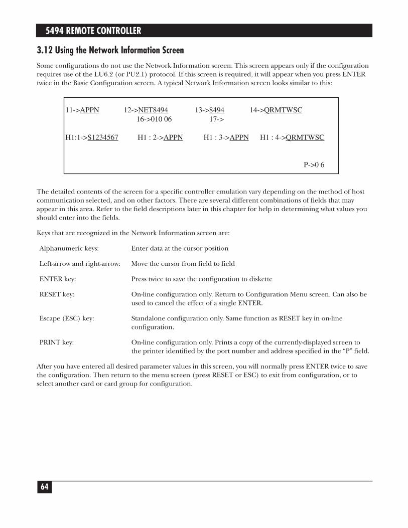
5494 REMOTE CONTROLLER
64
3.12 Using the Network Information ScreenSome configurations do not use the Network Information screen. This screen appears only if the configurationrequires use of the LU6.2 (or PU2.1) protocol. If this screen is required, it will appear when you press ENTERtwice in the Basic Configuration screen. A typical Network Information screen looks similar to this:
The detailed contents of the screen for a specific controller emulation vary depending on the method of hostcommunication selected, and on other factors. There are several different combinations of fields that mayappear in this area. Refer to the field descriptions later in this chapter for help in determining what values youshould enter into the fields.
Keys that are recognized in the Network Information screen are:
Alphanumeric keys: Enter data at the cursor position
Left-arrow and right-arrow: Move the cursor from field to field
ENTER key: Press twice to save the configuration to diskette
RESET key: On-line configuration only. Return to Configuration Menu screen. Can also beused to cancel the effect of a single ENTER.
Escape (ESC) key: Standalone configuration only. Same function as RESET key in on-lineconfiguration.
PRINT key: On-line configuration only. Prints a copy of the currently-displayed screen tothe printer identified by the port number and address specified in the “P” field.
After you have entered all desired parameter values in this screen, you will normally press ENTER twice to savethe configuration. Then return to the menu screen (press RESET or ESC) to exit from configuration, or toselect another card or card group for configuration.
11->APPN 12->NET8494 13->8494 14->QRMTWSC16->010 06 17->
H1:1->S1234567 H1 : 2->APPN H1 : 3->APPN H1 : 4->QRMTWSC
P->0 6

CHAPTER 3: Controller Installation
65
3.13 Configuration Parameter FieldsAA Communications Mode:Selects from available host communications modes:
0 = SDLC4 = Token-Ring5 = Ethernet
BB Emulation Mode:Indicates the kinds of IBM remote controller being emulated.
0 = 53941 = 52942 = 5494
This field cannot be changed in the Basic Configuration screen. It reflects the emulation that was selected inthe Configuration Menu screen.
DD SNA LU6.2/PU2.1 Node Support:This field is used to select SNA LU6.2/PU2.1 node support. A zero (0) in this field indicates no SNALU6.2/PU2.1 node support, and a one (1) indicates that SNA LU6.2/PU2.1 node support is active. This willallow connection to an APPN network or SNA subarea network. A second screen with additional configurationparameters will appear as the configuration values on the current screen are saved. If zero is entered in thisfield when configuring a LAN Gateway (Configuration Menu Option 7), the LAN gateway will be disabled.
DX Type of LAN:This field is used to select the type and/or speed of the LAN network attached to the PC394A-R3. Valid entriesare:
1 = Token-Ring, 4 MB, DB9 connection2 = Token-Ring, 4 MB, RJ-45 connection3 = Token-Ring, 16 MB, DB9 connection4 = Token-Ring, 16 MB, RJ-45 connection5 = Ethernet, BNC connection6 = Ethernet, RJ-45 connection7 = Ethernet, DB15 AUI connection

5494 REMOTE CONTROLLER
66
1 Language:The default language is U.S. (00). See the table below for the codes used to set the controller for otherlanguages. The language selection must match that configured on the host.
Language Codes
Code Description Code Description00 US/Canada 18 Portugal01 Japan Katakana 19 Portugal Universal02 Japan English 1A France Qwerty03 Japan Universal 1B France Qwerty Universal04 France Azerty 1C Spain05 France Azerty Universal 1D Spain Universal06 Belgium 1E Sweden07 Belgium Universal 1F Sweden Universal08 Canada (French) 20 Brazil09 Canada Universal 21 Brazil Universal0A Denmark 22 Austria/Germany0B Denmark Universal 23 Austria/Germany Universal0C Finland 24 US/Canada Universal0D Finland Universal 25 Mixed Swiss/French0E Spanish Speaking 26 Mixed Swiss/French Universal0F Spanish Speaking Universal 27 Mixed Swiss/German10 Italy 28 Mixed Swiss/German Universal11 Italy Universal 29 Swiss/French12 United Kingdom 2A Swiss/French Universal13 United Kingdom Universal 2B Swiss/Germany14 International 2C Swiss/Germany Universal15 International Universal 2D ASCII16 Norway 2E ASCII Universal17 Norway Universal
2 Controller Address:For SDLC, the controller address should be the same address as that used in the host configuration. Allowablevalues range from 01 to FE. Change the default setting of 00 to the correct address for the controller.
3 SDLC Communication Options:The second digit indicates whether the modem is set to duplex or half-duplex. Set the second digit to a 1 forduplex or 0 for half-duplex. The third digit specifies connection type. Set this digit to 0 for Multipoint or 1 forPoint-to-Point. Note that only Point-to-Point can be used with the full-duplex option. The fourth digit should be0 for NRZI or 1 for NONRZI. The selection for this digit must be the same as the used in the hostconfiguration.
10 SDLC Baud Rate:This field indicates the baud rate of the built-in modem eliminator when the Remote Controller is attacheddirectly to the host. If the Remote Controller is attached to a modem, the contents of this field will be ignored.
If the Remote Controller is attached directly to the host without a modem, the recommended baud rate is19,200 bps, except on the IBM 5364, which should use 9600 bps.

CHAPTER 3: Controller Installation
67
E Ethernet Frame Format:0 (zero) is the only valid option for this field, indicating that IEEE 802.3 frame format is being used.
F Local LAN SAP:Set the SAP value for the Remote Controller. Values must be hexadecimal and range from 04 to FC in multiplesof 04. Default value is 04.
G LAN Response Timer (T1):Defines the response timer (T1) for the Remote Controller. It is the maximum number of seconds allowed todetect a failure to receive a required acknowledgment on response from the remote link station. This valuemust be greater than the total number of delays that a frame might receive in the network. Valid values rangefrom 01 to 20 seconds. Default value is 01.
H LAN Inactive Timer (Ti):Defines the inactive timer for the Remote Controller. Whenever the response timer is not running, the RemoteController inactivity timer is running. If this timer expires, the communications link can be lost. If so, thecontroller will attempt to re-establish communication. This value should be at least 5 to 10 times greater thanthe response timer (T1). Default value is 30.
I LAN Receiver Acknowledgement Timer (T2):The acknowledgment timer must be set to a value that is less than the Response Timer (T1) setting at the linkstation. This value is the maximum number of milliseconds allowed before acknowledgments are sent to theAS/400 system. Default value is 030.
J LAN Retry Count (N2):This field defines the maximum number of times the Remote Controller will check the status of a receiving linkstation after the Remote Controller Response Timer (T1) expires. The combination of the T1 value and theRetry Count (N2) value must be large enough to allow for error detection and recovery on the network. Validvalues range from 01 to 99 with a default value of 08. A setting of 10 retries or less is typical.
K LAN Address (LAN Gateway):This field defines the Remote Controller’s LAN address. You can allow the Remote Controller to use its LANadapter’s native burned-in address, or you can override the native address with a locally-administered addressthat you specify. Use the 1-character prefix portion of this field to select from 3 available modes:
Prefix 0: Use a locally-administered address. The first four digits of the adapter address will be forced tobe 4000 (if token-ring) or 0200 (if Ethernet). You must provide the eight remaininghexadecimal digits of the address to be used.
Prefix 1: Use a locally-administered address, in bit-swapped format. Use this option only if you are usingtoken-ring LAN attachment but wish to enter the LAN address in Ethernet format, or if you areusing Ethernet LAN attachment but wish to enter the LAN address in token-ring format. Thisoption is intended primarily for use when there is a token-ring to Ethernet bridge between theclient workstations and the controller. The first four digits of the adapter address will be forcedto be 0200 (if token-ring) or 4000 (if Ethernet). You must provide the eight remaininghexadecimal digits of the address to be used.
Prefix 2: Use the adapter’s native address. The 12-digit portion of the field will remain blank.

5494 REMOTE CONTROLLER
68
NOTEWhen your controller is operating in normal mode, you can determine what its LANaddress is by going to any attached display station and keying the sequence ALT-HEX,CMD7. The LAN address will be displayed on the display’s error line, both in normaland bit-swapped form.
L LAN Gateway Service Access Point (SAP):Set the SAP value. Values must be hexadecimal and range from 04 to FC in multiples of 04. Default value is 04.
M LAN Gateway Response Timer (T1):Defines the LAN response timer (T1), which is the maximum number of seconds allowed to detect a failure toreceive a required acknowledgement on response from the remote link station. This value must be greater thanthe total number of delays that a frame might receive in the network. Valid values range from 01 to 20 seconds.Default value is 01.
N LAN Gateway Inactive Timer (T1):Defines the LAN inactive timer. Whenever the response timer is not running, the Remote Controller inactivitytimer is running. If this timer expires, the communications link can be lost. If so, the controller will attempt tore-establish communications. Valid values range from 01 to 99 seconds. Default value is 30.
O LAN Gateway Receiver Acknowledgement Timer (T2):The acknowledgement timer must be set to a value that is less than the Response Timer (T1) setting at the linkstation. Valid values range from 001 to 225 milliseconds. A setting of 30 to 255 milliseconds is typical. Defaultvalue is 030.
P Printer Address:Refers to printer that should print printouts of the configuration screen during the configuration of theRemote Controller (printouts are requested via the Print key).
The first digit indicates the port the printer is attached to. The second digit indicates the printer’s address.
Q LAN Gateway Retry Count (N2):This field defines the maximum number of times the Remote Controller will check the status of a receiving linkstation after the Remote Controller Response Timer (T1) expires. The combination of the T1 value and theRetry Count (N2) value must be large enough to allow for error detection and recovery on the network. Validvalues range from 01 to 99 with a default value of 08. A setting of 10 retries or less is typical.
R LAN Gateway Maximum Out (TW):This field defines the maximum number of sequentially numbered frames that the Remote Controller can sendbefore waiting for an acknowledgement. This value must be at least twice the value of the Maximum In (N3)count at the receiving IWS. Otherwise, network response time can severely degraded. Valid values range from 2to 8. Default value is 2.
S LAN Gateway Maximum In (N3):This field defines the maximum number of frames the Remote Controller can receive from the AS/400 beforesending an acknowledgement. This value must not be more than one-half of the Maximum Out (TW) value atthe sending link station. Valid values range from 1 to 4. Default is 1.
11 Local Network ID:Enter the local network ID. This name will be used as a default if the AS/400 network is not provided for thehost (field H1:2).

CHAPTER 3: Controller Installation
69
12 8494 Logical Unit (LU) Name:This parameter must match the remote location name configured on the AS/400 for this controller (differentfor each emulated controller). Refer to the Quick Setup Guide. Leave this field blank if you are configuring aLAN gateway (Configuration Option 7).
13 8494 Control Point (CP) Name:This parameter must match the remote control point name in the APPC Controller description on the hostAS/400. This name must begin with a letter. It cannot begin with a number.
14 Default Mode Name:This mode name is used as a default if the AS/400 mode name is not provided for the host (field H1:4). Thisparameter (if used) must match the mode name configured on the AS/400. Refer to the Quick Setup Guide.
15 Connection Number:You must make an entry in this field if you use LAN host attachment; the field is not used for SDLC, and isoptional for X.25 host attachment.
For LAN host attachment, this field defines the Remote Controller’s own LAN address. The Remote Controllercan use its LAN adapter’s native burned-in address, or it can override the native address with a locally-administered address that you specify. Use the 1-character prefix portion of this field to select from 3 availablemodes:
Prefix 0: Use a locally-administered address. The first four digits of the adapter address will be forced tobe 4000 (if token-ring) or 0200 (if Ethernet). You must provide the eight remaininghexadecimal digits of the address to be used.
Prefix 1: Use a locally-administered address, in bit-swapped format. Use this option only if you are usingtoken-ring host attachment but wish to enter the LAN address in Ethernet format, or if you areusing Ethernet host attachment but wish to enter the LAN address in token-ring format. Thisoption is intended primarily for use when there is a token-ring to Ethernet bridge between thehost and the controller. The first four digits of the adapter address will be forced to be 0200 (iftoken-ring) or 4000 (if Ethernet). You must provide the eight remaining hexadecimal digits ofthe address to be used.
Prefix 2: Use the adapter’s native address. The 12-digit portion of the field will remain blank.
NOTEWhen your controller is operating in normal mode, determine what its LAN address isby going to any attached display station and keying the sequence ALT-HEX, CMD7.The LAN address will be displayed on the display’s error line, both in normal and bit-swapped form.
16 Retry Count and Retry Interval:The retry count specifies the number of retries the Remote Controller will make to re-establish the controllersession with the AS/400. Valid values range from 000 to 255. Default value is 10.
The retry interval specifies the number of 10-second intervals between the retries. Valid values range from 1 to60 with a default value of 6 (60 seconds).

5494 REMOTE CONTROLLER
70
17 Serial Number:This field is used to enter the Remote Controller’s serial number. The number will be sent to the AS/400 whencommunication is established. This is not a required field, if no number is provided, zeros will be used. If theserial number is larger than the field, exclude the last digits or use zeros for this field.
H1:1 AS/400 Logical Unit Name:This parameter must match the local location name configured on the AS/400.
H1:2 AS/400 Network Name:This parameter must match the local network ID configured on the AS/400.
NOTEIf this field is left blank, the default local network name (field 11) will be used.
H1:3 AS/400 Local Network Name:This parameter must match the remote network ID configured on the AS/400.
NOTEIf this field is left blank, the default local network name (field 11) will be used.
H1:4 Mode Name:Enter the remote controller’s mode name. If used, this parameter must match the mode name configured onthe AS/400.
NOTEIf this field is blank, then the Default Mode Name (field 14) will be used.
H1:5 AS/400 Connection Number:You must make an entry in this field if you use LAN host attachment; the field is not used for SDLC.
For LAN host attachment, this field defines the host computer’s LAN address. Use the 1-character prefixportion of this field to select from 2 available modes:
Prefix 0: Enter the host LAN address in normal format (token-ring format for token-ring attachment,Ethernet format for Ethernet attachment).
Prefix 1: Enter the host LAN address in bit-swapped format. Use this option only if you are using token-ring host attachment but wish to enter the LAN address in Ethernet format, or if you are usingEthernet host attachment but wish to enter the LAN address in token-ring format. This optionis intended primarily for use when there is a token-ring to Ethernet bridge between the hostand the controller.
H1:7 AS/400 System SAP:Enter the appropriate AS/400 SAP in this field. Valid values are hexadecimal 04 to FC in new links of 04.Default value is 04.
H1:8 AS/400 System Maximum Out (TW):Valid values are 2 to 8. Default value is 2. Enter appropriate maximum out value.

CHAPTER 3: Controller Installation
71
H1:9 AS/400 System Maximum In (N3):Valid values are 1 to 4. Default value is 1. Enter appropriate value.
3.14 Concurrent Host AttachmentConcurrent host attachment is configured by filling in fields H1:1 through H2:4, H3:1 through H3:4 and H4:1through H4:4. (See Appendix E for further information.)
The Primary AS/400 is identified in the 8494 configuration screen ad H1:1. The fields H1:1 through H1:4describe the Remote Controller’s connection to the Primary host. Fields contained in H2, H3, and H4 refer tothe secondary AS/400 hosts. The last field on each concurrent host attachment line should contain theQRMTWSC mode.
H1:1-> _______ H1:2-> ________ H1:3->_________ H1:4->QRMTWSC
H2:1-> _______ H2:2-> ________ H2:3->_________ H2:4->QRMTWSC
H3:1-> _______ H3:2-> ________ H3:3->_________ H3:4->QRMTWSC
H4:1-> _______ H4:2-> ________ H4:3->_________ H4:4->QRMTWSC

5494 REMOTE CONTROLLER
72
4. OperationBefore you power on the Remote Controller, insert the system diskette in the diskette drive with the label facingupward and make sure the switch on the front panel is set to Normal. Then power on the controller with thepower switch on the front panel.
NOTEDo not remove the system diskette from the drive until the disk access light has goneout.
When the Remote Controller is powered on and working correctly, the front-panel display will show “Ready.”
After the controller is powered on and the attached devices are communicating (cursor in the upper left cornerof the attached display stations), communications with the host must be established. If your controller is usingSDLC communications, this is done by varying the line and the controller on.
Establish SDLC ConnectionIf the Remote Controller uses the SDLC communications mode, vary on the controller from the host toestablish host/controller communications. The method for varying on differs on each host system as describedin the following sections.
AS/400
On an AS/400 host, do the following to vary on the Remote Controller.
1. From the main menu, select option 6, “Communications.”
2. From the communications menu, choose “Configure Communications and Remote Hardware Menu.”
3. Select position 1, “Lines.”
4. When the Work with Line Descriptions menu is displayed, press the F14 key, “Work with status.”
5. Enter a 1 in front of the line description to vary on the line. The controller description should vary on aswell.
SYSTEM/38
On a System/38 host, do the following to vary on the Remote Controller:
1. From menu LIN, Line Menu, select option 5, “Vary Line” and vary on the line. (This should vary on line,CTRL, and devices.)
2. From menu CTLU, Control Unit Menu, select option 3, “Vary Control Unit” and vary on the control unit.
3. From menu DEV, Device Menu, select option 9, “Vary Device,” and vary the devices on line.
After approximately ten seconds, the IBM sign-on menu should appear on the terminals attached to theRemote Controller.

CHAPTER 4: Operation
73
SYSTEM/36
On the System/36 host, vary on the line/devices with one of the following commands:
V ON,,1 Vary on all the control units/devices on line 1.V ON,C01 Vary on all the devices attached to Control Unit C01 (the character after the “C” is a zero).V ON,W1 Vary on workstation W1.
The values 1, C01, and W1 are optional values that change depending on what line, control unit, or device isbeing varied ON or OFF. To vary off a line, control unit, or device while on-line, change the command fromON to OFF.
After approximately ten seconds, the IBM sign-on menu should appear on the terminals attached to theRemote Controller.

5494 REMOTE CONTROLLER
74
5. Problem Resolution5.1 IBM Verification TestVerification tests check workstations and printers attached to the Remote Controller. Throughout these testsyou are required to make selections from a menu. If you make an error, you can do one of the following:
• Press BACKSPACE and enter the correct selection, or
• Press “C” and ENTER to return to the previous menu and make the correct selection.
To run the verification tests on the System/36, System/38, or AS/400:
1. If necessary, start communications with the host system (refer to Chapter 4).
2. When the sign-on screen displays, press the CMD key followed by the TEST REQUEST (CharacterBackspace) key. If you have a 102-key or 122-key keyboard, press and hold the ALT key while you press theTEST key. The Test Request menu will appear.
3. Select the desired options from the following:
Previous screen:Press “C” and ENTER to return to the previous screen.
End:This option returns you to the Prime Option menu.
Display Verification: This option provides test patterns that show various character display capabilities; a test is also performedon the function keys.
Work Station Printer Verification:This option checks out a printer. A printed report shows print patterns.
Configuration Data:This option displays descriptive information, such as system addresses, for the twinax card the display isattached to.
ERAP:This option is not supported by the Remote Controller.
Follow the instructions and prompts provided with each option to complete the verification test.
NOTESee the appropriate workstation/printer manual for operational requirements andmeaning of error codes.

CHAPTER 5: Problem Resolution
75
5.2 Problem-Resolution GuideThe problem-resolution guide on the following pages describes common problems with the Remote Controllerand solutions.
If the controller does not power on, check that the controller’s power cord is plugged in, the controller ispowered on, and the power outlet to the controller has power.
If you have problems with a twinax connection, check the installation of the twinax cards. Make sure the cardsare installed properly and the switches and jumpers on the cards are set properly.
The most common problem in device installations is cabling. Make sure all devices are properly attached, theend of each cable line is terminated properly, and do not exceed the maximum cable connections (11) allowedper line. Do not place twinax cables over or near power sources, as this disrupts the communication signalsflowing in the cable. Locate cables at least one foot (0.3 m) away from all power sources. Check each cable ifnecessary to determine if the cable is faulty.
Host configuration, modem settings, and the controller configuration are also common problems. Since thedevices attached to the controller must be recognized by the host, make certain the device configuration(device description, address, emulation) at the controller matches the device configuration at the host. CheckNRZI vs. NONRZI if using SDLC communications. This setting must be the same on the host and thecontroller. Make sure the modem settings match the type of network the controller is operating on.
NOTEError codes that may appear on display stations due to operator or system errors arelisted and described in Appendix C.
If the display station or remote controller does not communicate with the host, the ENTER key must be pressedfor the applicable error code to be displayed.
Problem Probable Cause ActionNo power to Power cord not plugged in. Check power-cord connection.controller (LEDs No power at outlet. Check wall outlet.remain dark). Controller not powered on. Power on the controller with the front-panel switch.
Ready light Faulty, damaged, or Most common problem. Isolate each cable length and twinax doesn’t come on improper cabling. connector to make sure it is not faulty. Change with known goodor remains cables if necessary. Check each connection for good contact flashing. (no pushed pins). Make sure cables are not routed near power
sources. If using twisted-pair cabling, check balun compatibility (some baluns are for specific uses only).
Error in software diskette. Verify proper insertion of diskette and retry; try backup diskette. Ifunsuccessful, call for technical support.
Defective twinax card. Check MPIC and twinax card LEDs for card status. See discussionof Remote Controller status later in this chapter.
Twinax card(s) or interface Make sure card(s) is fully seated in the controller, DIP switches arecard not installed properly. set properly, and the interface card is fully seated.Improper termination. Make sure each cable run is terminated properly. Make sure the last
device on the cable is terminated properly; exchange with a knowngood device if necessary.

5494 REMOTE CONTROLLER
76
Problem Probable Cause ActionUnable to Faulty, damaged, or Most common problem. Isolate each cable length and twinax configure work- improper cabling. connector and make sure it is not faulty. Change with known goodstations on the cables if necessary. Check each connection for good contact (no5494 Remote pushed pins). Make sure cables are not routed near power sources.Controller If using twisted-pair cabling, check balun compatibility (some baluns
are for specific uses only).Duplicate device address. Verify that all devices are connected to the proper port and set at
the correct address as the configuration at host.TEST switch (see Chapter Power controller off, turn TEST switch ON, then power controller on.3) is not set ON.Devices not connected or Verify proper cable connection and that all devices are powered onnot powered on. and in “Ready” state.Wrong selections on the Use scroll up/down keys to change values in controller to hostconfiguration screen configuration fields.(Chapter 2).Modem is attached to the Controller will not configure with active modem attached.controller and is active. Disconnect the modem cable, configure the controller, then
reattach the modem cable.Improper termination. Make sure each cable run is terminated properly. Make sure the
last device on the cable is terminated properly; exchange with a known good device if necessary.
Device does not Faulty, damaged, or Most common problem. Isolate each cable length and twinaxshow up on improper cabling. connector and make sure it is not faulty. Change with knownconfiguration good cables if necessary. Check each connection for good contactscreen. (no pushed pins). Make sure cables are not routed near power
sources. If using twisted-pair cabling, check balun compatibility (some baluns are for specific uses only).
Device not powered on, Power device on, make sure it is in a ready state (printers may neednot in ready state, or paper loaded to show ready), try known good device in place of the faulty. suspect one. Displays will show a copyright and twinax card
number in the upper right corner of the screen when it’s recognizedby the controller.
PC emulator not in PCs with emulator cards must be in emulation mode during emulation mode. configuration of the controller.
Configuration will Test switch not ON. Power off the controller, put the test switch on the front panel in thewill not store ON position, then power the controller on.properly. Configuration-screen sel- Follow the steps under the section Configure the Remote Controller
ections not made for each in Chapter 3. Each card installed in the controller must be con-twinax card installed. figured and the configuration saved to diskette before continuing to
the next card’s configuration.Controller hasn’t stored the Do not proceed to configure additional twinax cards before the diskprevious configuration to access light goes off so the configuration for the preceding twinaxdiskette. card is stored.

CHAPTER 5: Problem Resolution
77
Problem Probable Cause ActionConfiguration will Diskette not in drive; Make sure diskette is in the drive, label side up. Try backup will not store diskette write-protected or diskette if necessary.properly faulty.(continued). Request to store config- Be sure to press the ENTER key twice after entering all desired
uration not properly keyed. parameters into fields on the configuration screen.
No host Host communication line Contact your system operator; may need to IPL the host. Make surecommunication; not operating properly. host/modem cable is attached to controller. Have line checked by controller won’t phone company.come on-line or NRZI or NONRZI not set NRZI and/or NONRZI setting must be the same at both the host andcannot be varied properly. the controller. If you are unsure, change this setting at the controlleron. and try to bring it on-line again.
Controller hasn’t been Configure the controller as described in Chapter 3.configured.Local configuration does Verify that local configuration matches host configuration. The mostnot match the host’s common configuration mismatches are controller address (Field 2 configuration. on configuration screen) and emulation mode (field BB). Note that
for the S/36 and S/38 hosts, Field BB MUST be set to 1 (5294emulation mode), as these hosts do not support the 5394 mode. Forall hosts, the number in Field 2 must match the stations addressconfigured for the controller on the host.
Modem is not the proper Verify proper modem type for the network. Make sure modem cantype or not strapped communicate at the line speed you have chosen. Check that the properly. modem is “strapped” for the network type (half or full duplex, etc.).
Perform loopback or end-to-end tests to make sure host-site and controller-site modems can communicate.
Host not configured for the Make sure the host is configured for the controller. Each twinaxcontroller. card installed is recognized by the host as a separate controller.Host configuration not Make sure the controller address is correct at the host, the correct. emulation (5294, 5394, or 5494) is correct at the host, the network
type (point-to-point, multipoint, etc.) is correct (a multiple-cardcontroller must use a multipoint network), NRZI or NONRZI is the same at the host and controller, and the XID is correct at the host.
Controller not varied on or Vary on the controller as described in Chapter 4. Some hosts subsystem not started. require the line, device and subsystem to be varied on before the
host can communicate. Make sure subsystem is started.Twinax cabling is damaged Make sure cable and all connections are not damaged. Verify thator improper. all IBM cabling conventions are followed, including line length (not
greater than 5,000 feet) and proper termination of all devices; verifyall on-line devices are operating correctly.
Workstation(s) Faulty, damaged, or Most common problem. Isolate each cable length and twinaxdrop off line or improper cabling. connector and make sure it is not faulty. Change with known goodwill not come up. cables if necessary. Check each connection for good contact (no
pushed pins). Make sure cables are not routed near power sources.If using twisted-pair cabling, check balun compatibility.

5494 REMOTE CONTROLLER
78
Problem Probable Cause ActionWorkstation(s) Conflicting device descrip- Remove device descriptions from the configuration record at the drop off line or tions on the host. host for devices not configured on the remote controller.will not come up Improper termination. Make sure each cable run is terminated properly. Make sure the(continued). last device on the cable is terminated properly; exchange with a
known good device if necessary.Device damaged. Change with a known good device to verify proper operation. If the
device is damaged, repair or replace it.
Controller drops Telephone line has Have the phone company check the telephone line.off-line and will interference.not come back Active job on host or in Delete job and continue.up or stays at a spool file.“Vary on Message on console. Answer then delete message.pending” status. Modem or controller Power off then power on both modems and the controller.
“locked up.”Subsystem terminated. Restart subsystem.Drop line upon sign off Select “No” to the drop off line upon sign off in the controllerselected as “yes” on the description.controller description(AS/400).Interference on communi- Check communications line to host for interference.cations line.Selected baud rate is too Increase baud rate in controller configuration and on modem slow for the number of settings.attached devices or theapplication.Host has nonexistent Check the host status of the line for this controller. If the line showscontroller varied on a any nonexistent controllers as having status other than “varied off,”multipoint line. vary them off.
Disk Error Light Diskette is not bootable. Try booting from the spare controller diskette.appears. Loose cards. Make sure all of the controller’s cards are in the slots tightly. Reseat
cards.

CHAPTER 5: Problem Resolution
79
5.3 Remote Controller
There are LED status indicators on the back of the Remote Controller. These LEDs will help you determine thestatus of host communications and the condition of the twinax card(s) installed in the controller.
5.3.1 TWINAX CARDS
Each twinax card has two LEDs, one at the top for the upper port and one at the bottom for the lower port.The LEDs have four possible indications:
Flashing rapidly:Software is being downloaded to the twinax card.
Flashing slowly:Twinax card is active, but no devices are connected.
Steady on:Twinax card is active and devices are connected (normal working status).
Off:Twinax card is not active. This indication will be accompanied by a flashing ready indicator on the front panel and an error status for this card on the card indicators.
5.3.2 MPIC CARD
The Multipurpose Communications Interface Card (MPIC) has five LEDs underneath the host port. If some ofthe LEDs remain lighted, use the diagrams on the next page to determine the status. When the lights indicate adefective twinax card, the problem may be either the card itself or most likely a cable attached to the card. Thefollowing procedure can further isolate the problem.
1. Turn off power to the controller.
2. Tag all twinax cables with Slot #/ Port # labels.
3. Disconnect all twinax cables from all twinax cards.
4. Turn on power to the controller, and wait for either a steady “Ready” light or a reappearance of the LEDerror indication.
5. If an error is reported when all cables are disconnected, a defective card is indicated. Otherwise, adefective cable is indicated. In the latter case, the faulty cable can be isolated by connecting eachindividual cable in turn and repeating the power-off/power-on sequence.

5494 REMOTE CONTROLLER
80
NOTE5 LEDs on means that there is insufficient memory.
A filled circle indicates LED On.
5.4 LEDs on the Front PanelTop Row Description
POWER When on, indicates that +5 VDC is present.
TEST When on, indicates that the TEST switch is set to ON for configuration purposes.
READY When on, indicates that the power-on sequence has been successfully completed and theremote controller is ready for operation. When flashing, indicates an error condition.Check LEDs on the MPIC card and twinax cards.
Twinax Card #1 defective Twinax Card #2 defective Twinax Card #3 defective
Twinax Card #4 defective Twinax Card #5 defective Twinax Card #6 defective
MPIC Card defective
Error while reading theconfiguration fileCause: a) faulty diskette;b) faulty diskette drive
Error while reading thetwinax card .hex fileCause: a) faulty diskette;b) faulty diskette drive

CHAPTER 5: Problem Resolution
81
COM LINE When flashing, indicates that valid data bytes are being received from the communicationsline.
WS ACTIVE When on, indicates that one or more attached workstations are responding to polls.
DISK ERROR When on, indicates one of the following error conditions:
a. Faulty disketteb. Faulty diskette drivec. Faulty floppy disk controller
NOTEThe Disk Error LED might come on briefly during the loading of the operation softwareand then extinguish after the operating software is loaded. This does not indicate anerror.
These LEDs give an indication of the status of the signals as they are being received and transmitted to themodem or equivalent equipment.
Bottom Row Description
TXD (Transmitted Data) When flashing, indicates data is being transmitted from the remotecontroller to the modem.
RXD (Received Data) When flashing, indicates data is being received by the remote controllerfrom the modem. This LED will appear steady (solid) at high transmission speeds.
RTS (Request to Send) Asserted by the remote controller to indicate it has data to send.
CTS (RFS, Clear to Send) Asserted by the modem in response to the RTS signal. This signalallows the remote controller to transmit.
DSR (Data Set Ready) Asserted by the modem when it is powered on and ready to function.Note: This LED should be on continuously during normal operation.
DTR (Data Terminal Ready) Indicates to the modem that the remote controller is ready tooperate. Note: This LED should be on continuously during normal operation.
CD (DCD, Carrier Detected) Asserted by the modem when the remote host has control of theline and is transmitting (some systems assert carrier continuously).
TXC (TEST, Transmitted Signal Element Timing) When on, indicates the transmit clocksupplied by the modem is present. For local attachment, the remote controller has a built-in modem eliminator which supplies the appropriate signals and clocks. Note: This LEDshould be ON continuously during normal operation.
RXC (RSET, Received Signal Element Timing) When on, indicates that the receive clocksupplied by the modem is present (this clock may only be present during the receipt ofdata). For local attachment, the remote controller has a built-in modem eliminator whichsupplies the appropriate signals and clocks.

5494 REMOTE CONTROLLER
82
5.5 Keyboard Entry ErrorsOne of the following may happen when a keyboard entry error occurs.
• The keyboard locks.
• The “inhibit” message appears at the bottom of the screen.
• A system error code is displayed in the left-hand corner of the screen (see Section C.1).
An error may occur due to one of the following reasons.
• The system is not accepting the key you just pressed.
• There is something wrong with the system.
• There is something wrong with your display station.
To recover from the error, press the ERROR RESET key and continue to input information. If you are unableto recover from an error condition, contact your systems programmer. If you need further information, refer tothe display station’s documentation.
NOTEAfter sign-on, you can press the Help key to display a message that describes theerror.
5.6 Calling Black BoxIf you determine that your Remote Controller is malfunctioning, do not attempt to alter or repair the unit. Itcontains no user-serviceable parts. Contact Black Box at 724-746-5500.
Before you do, make a record of the history of the problem. We will be able to provide more efficient andaccurate assistance if you have a complete description, including:
• the nature and duration of the problem.
• when the problem occurs.
• the components involved in the problem.
• any particular application that, when used, appears to create the problem or make it worse.
5.7 Shipping and PackagingIf you need to transport or ship your Remote Controller:
• Package it carefully. We recommend that you use the original container.
• If you are shipping the Remote Controller for repair, make sure you include everything that came in theoriginal package. Before you ship, contact Black Box to get a Return Materials Authorization (RMA)number.

APPENDIX A: Related Documentation
83
Appendix A. RelatedDocumentation
The following manuals may be helpful in installing and operating the Remote Controller and attached devices.
IBM 5250 Information Display System Introduction, GA21-9246.Describes the workstations that make up the 5250 information display system and their available functions andfeatures.
IBM 5250 Information Display System Planning and Site Preparation Guide, GA21-9337.Provides information on system limitations and physical planning, including detailed cabling and switch setting.
IBM 5250 Information Display System Functions Reference Manual, SA21-9247.Provides information about SNA, SDLC, and Data Streams for 5250 type devices.
IBM Systems Network Architecture Concepts and Products Manual, GC30-3072.Presents an overview of SNA including basic descriptions of terminology, concepts, and scope.
IBM Synchronous Data Link Control General Information, GA27-3093.Describes procedures that make up synchronous data link control (SDLC), a brief background, and a basicdescription of the terminology and concepts of SDLC.
IBM System/36 Changing Your System Configuration, SC21-9052.Provides instructions and reference information on how to change your system configuration.
IBM System/38 Guide to Program Products Installation and Device Configuration, GC21-7775.Gives setup and configuration information.
IBM AS/400 Device Configuration Guide, SC21-8106.Gives setup and configuration information.
IBM 5394 Remote Control Unit Type 2.1 Node Support RPQ 8Q0775, SC30-3531-01.Explains how to set up, configure, and operate Control Unit Type 2.1 Node Support RPQ.
IBM 5494 Remote Control Unit Attachment to Subarea Network RPQ 8Q0932, SC30-3566-01.Explains how to set up, configure, and operate control unit attachment to Subarea Network RPQ.

5494 REMOTE CONTROLLER
84
Appendix B. Multiple LanguagesTake the following steps to configure the 5494 Remote Controller for one of the available languages shown onthe next page.
1. Display the configuration screen using these keystrokes:
• 83 keyboard - CMD, BACKSPACE• 102 keyboard - Press and hold ALT, then press TEST• 122 keyboard - Press and hold ALT, then press TEST
2. Use the CURSOR LEFT or CURSOR RIGHT key to position the cursor under field 1, which specifies thelanguage code to be used.
3. Use the CURSOR UP or CURSOR DOWN key to select the language code.
4. Press the ENTER key twice to save the configuration. This selects a “master” language code, which willapply to all display stations attached to the workstation controller card being configured. If you did notselect a universal language code or you do not require multiple languages, skip to step 12. Continue tostep 5 to configure specific display stations for language codes that are different from the “master”language code.
5. Use the CURSOR UP and CURSOR DOWN keys at field 1 to select the language code for the displaystation using a language code that is different from the “master” language code. This code must be auniversal code.
6. Use the CURSOR RIGHT key to position the cursor under the first of the two dashes.
7. Use the CURSOR UP and CURSOR DOWN keys to select the port number of the desired display.
8. Use the CURSOR RIGHT key to position the cursor under the second dash.
9. Use the CURSOR UP or CURSOR DOWN keys to select the workstation address of the desired display.
10. Press the ENTER key twice to save the configuration of the display station.
11. Repeat steps 5 through 10 for any other display stations using language code that differs from the “master”language code.
12. When finished, press ERROR RESET to exit from the configuration menu.

APPENDIX B: Multiple Languages
85
Language Codes
Code Description Code Description00 US/Canada 18 Portugal01 Japan Katakana 19 Portugal Universal02 Japan English 1A France Qwerty03 Japan Universal 1B France Qwerty Universal04 France Azerty 1C Spain05 France Azerty Universal 1D Spain Universal06 Belgium 1E Sweden07 Belgium Universal 1F Sweden Universal08 Canada (French) 20 Brazil09 Canada Universal 21 Brazil Universal0A Denmark 22 Austria/Germany0B Denmark Universal 23 Austria/Germany Universal0C Finland 24 US/Canada Universal0D Finland Universal 25 Mixed Swiss/French0E Spanish Speaking 26 Mixed Swiss/French Universal0F Spanish Speaking Universal 27 Mixed Swiss/German10 Italy 28 Mixed Swiss/German Universal11 Italy Universal 29 Swiss/French12 United Kingdom 2A Swiss/French Universal13 United Kingdom Universal 2B Swiss/Germany14 International 2C Swiss/Germany Universal15 International Universal 2D ASCII16 Norway 2E ASCII Universal17 Norway Universal

5494 REMOTE CONTROLLER
86
Appendix C. System ReferenceCodes
This appendix provides a list of system reference codes (SRCs). System reference codes are error codes,counters, and messages used by the Remote Controller. When displayed, the SRC codes appear in the lowerleft-hand corner of the screen on display stations attached to the remote controller. Some error codes require aspecific key sequence to be displayed as specified (if applicable) for each type of error code.
NOTEThe 5494 Remote Controller will log any errors occurring during its last hour ofoperation. These can be displayed by pressing the ALT key and while holding itdepressed, pressing the HEX key, followed by the F3 key. Repeat the same keysequence to display the next to last logged error, etc.
System ReferenceCode (SRC) Reason Received Location Displayed
0000 through 003F An operator error occurred during an entry Display station where the erroroperation. originated.
0040 through 005F An error occurred on the communications network All affected display stations.during the time the 5494 Remote Controller wascommunicating with the host system.
0080 through 008F An error occurred during configuration of the Display station used for Remote Controller configuration of the Remote
Controller.
0090 through 0009F A display-station operator caused an error that Display station where the errorinvolves the host-system capabilities. originated.
0100 through 0145 An error occurred on the communications network All affected display stations.during the time the Remote Controller wascommunicating with the host system.
100000 through 10FFFF A display-station operator attempted to enter an Display station where the errorincorrect or invalid X.25 command or parameter originated.from the keyboard.
110000 through 1FFFFF An error was detected by the DTE or DCE on an All active display stations.X.25 network.
400000 through 5FFFFF An error related to the connected LAN was On a twinaxial connected displaydetected by the controller. station, press a key sequence
defined in Section C.4.

APPENDIX C: System Reference Codes
87
C.1 Operator Entry System Reference Codes
SRC Description Explanation0000 Help Key Not Allowed The display-station operator pressed the HELP key; however, either no SRC
appeared or the application program did not support the HELP key.
0001 Keyboard Overrun The Remote Controller did not keep up with the rate of information entered. The last character entered was not recognized.
0002 Invalid Scan Code The Remote Controller received an invalid key code from the display station.Either the keyboard code is incorrect for the keyboard at the display stationor an error occurred in translating the keystroke.
0003 Invalid Command/PF Key The display-station operator pressed either a COMMAND key sequence, a PFkey that was not supported or not valid for the current field, or an invalid ALT key sequence.
0004 Data Not Allowed in this The display-station operator tried to enter data from the keyboard into a Field field where only MSR or SLP entries are allowed.
0005 Cursor in Protected Area The display-station operator tried to enter data, but the cursor was not in anof Display input field on the display. Data cannot be entered in a protected area of the
display.
0006 Key Following Sys Req The display-station operator pressed the SYS REQ/ATTN key while Key Not Valid establishing an X.25 circuit or pressed an invalid key after pressing the SYS
REQ/ATTN key and before pressing the ENTER/REC ADV key or the ERRORRESET key.
0007 Mandatory Entry Field There is at least one mandatory entry field on the screen that the display-stationMust Enter Data operator must enter data into before the screen can be changed or processed.
(The cursor goes to the first character position of the first unentered mandatory entry field.)
0008 This Field Must Have The display-station operator tried to enter non-alphabetic characters into aAlphabetic Characters mandatory alphabetic field. Valid characters are A through Z, blank, comma,
period, hyphen, apostrophe, and DUP. The DUP key may be used to duplicatethese characters in the field.
0009 This Field Must Have The display-station operator attempted to enter nonnumeric characters into aNumeric Characters mandatory numeric field. Valid characters are 0 through 9, blank, comma,
period, plus, minus, and DUP. The DUP key may be used to duplicate thesecharacters in the field.
0010 Only Characters 0 The key pressed is not valid for a signed numeric field. Valid entries are 0Through 9 Permitted through 9 and DUP key.
0011 Key for Sign Position of The display-station operator tried to enter data into the last position of a signedField Not Valid numeric field.
0012 Insert Mode No Room to There is no room to insert data into this field. Either there is no room in theInsert Data field, or the cursor is in the last position of the field. Do not use Insert mode to
change data or to enter the last character in the field.

5494 REMOTE CONTROLLER
88
SRC Description Explanation0013 Insert Mode Only Data The display-station operator tried to exit a field while the display station was
Keys Permitted still in Insert mode.
0014 Mandatory-Fill Field The display-station operator pressed a function key that moves the cursor outMust Fill to Exit of this field; however, the requirements of this mandatory-fill field were not met.
A mandatory-fill field must be completely filled or left blank.
0015 Modulo 10 or 11 Check The display-station operator entered data into a self-check field, and theDigit Error number entered and the check digit did not compare.
0016 F-key Not Valid in this The display-station operator pressed the FIELD key when the cursor was notField in a numeric only, digits only, or signed numeric field.
0017 Mandatory-Fill Field Key The display-station operator pressed the FIELD-, FIELD+, or FIELD EXIT key;Pressed is Not Valid however, the requirements for this mandatory-fill field were not met. A
mandatory-fill field must be completely filled unless the operator exits it from the first position of the field.
0018 Key Used to Exit this Field The cursor is in a right-adjust or field-exit-required field, and the display-station Not Valid operator pressed a data key.
0019 Dup or Field Mark Key The display-station operator pressed the DUP or FIELD MARK key; however,Not Permitted in this Field the key is not permitted in this field.
0020 Function Key Not Valid for The display-station operator pressed a function key that is not permitted in thisRight-Adjust Field field. Press the FIELD EXIT, FIELD+, or FIELD- key to exit this field before
pressing one of the following function keys: TEST REQ, CLEAR, ENTER/REC ADV, PRINT, HELP, ROLL, HOME (when the cursor is in the homeposition), PF/CMD 1-24, SYS REQ, REC BACKSPACE.
0021 Mandatory Entry Field The cursor is positioned in a mandatory-entry field. The operator must enterMust Enter Data data into a mandatory-entry field before exiting the field by pressing the
FIELD+, FIELD-, or FIELD EXIT key.
0022 Status of Field Not Known A system error occurred. The status of the current field is not known. This error can occur during an insert or delete operation.
0023 Hex Mode Entry Not Valid The display-station operator is in hexadecimal mode, but the first or secondkey pressed was not a character 0 through 9 or A through F. This error also occurs when hexadecimal code is used in a numeric, signed numeric, alpha only, digits only, or I/O field.
0024 Decimal Field Entry Not The display-station operator pressed a key that is not valid. Only characters 0 Valid through 9 and the DUP key (if specified in the field format word) are allowed
in this field.
0026 Field-key Entry Not Valid The display-station operator pressed the FIELD key to exit a numeric-onlyfield, but the last position of the field was not a character 0 through 9.
0027 Key Not Defined Key The display-station operator pressed a key that is either blank or not definedCannot Be Used for this display station.
0029 Diacritic Character Not The second key pressed during a diacritic key function in a two-key sequenceValid did not produce a valid diacritic character.

APPENDIX C: System Reference Codes
89
SRC Description Explanation0031 Data Buffer Overflow The data received from the MSR card was longer than the maximum allowed.
0032 MSR Data Error Data received from the MSR was not valid.
0033 MSR Secure Data Read The MSR data received was not secured data (the operator ID card), and thisNot Authorized field was not specified for secured data.
0034 MSR Data Exceeds The magnetic-stripe-reader data received will not fit into the active input field.Length of Field
0035 MSR Error The card to be read was incorrectly inserted into the magnetic-stripe reader,was incorrectly made, or is damaged.
0036 Cursor Select Not Allowed The display-station operator pressed the CURSOR SELECT key while in a in Field Exit Required field exit required state.State
0037 Cursor Select Attempted The operator pressed the CURSOR SELECT key in a nonselectable field.in Nonselectable Field
0044 Token-Ring: No valid Verify that the 5494 Remote Controller cable to the modem/DCE is securelyframe before the time connected; that the modem/DCE is turned on; and that the communication(Ti) expired line is attached to the modem.
0046 X.25 or Token-Ring: Verify that the Remote Controller cable to the modem/DCE is securelyFrame reject received. connected; that the modem/DCE is turned on; and the communication line is
attached to the modem. If no problem is found, retry the procedure used to start AS/400 system communication. If this occurs again, call for technicalsupport.
0047 X.25 or Token-Ring: An Verify that the 5494 Remote Controller cable to the modem/DCE is securelyunexpected disconnect connected; that the modem/DCE is turned on; and the communication line ismode (DM) or a dis- attached to the modem. If no problem is found, retry the procedure used toconnect (DISC) command start AS/400 system communication. If this occurs again, call for technicalwas received while in support.information transfer state.
0081 Too many workstations The maximum number of attachments allowed is 8 or 16, depending on are attached to the 5494 emulation. Determine which workstations are extra and disconnect them.Remote Controller
0089 One or more fields When you press Enter, the Remote Controller checks for blank fields andrequired for operation are moves the cursor to the first blank. Press Error Reset and fill in the requiredblank field.
008A One or more fields contain When you press Enter, the Remote Controller checks for embedded blanksan embedded blank. and moves the cursor to the first embedded blank. Press Error Reset and fill
in the embedded blanks.
008C Same Logical Unit (LU) When you press Enter, the Remote Controller checks if the Logical Unit (LU) mode name used for two mode name (Field 12) has been used for another emulated controller. Pressemulated controllers. Error Reset and select another name, as found appropriate.

5494 REMOTE CONTROLLER
90
SRC Description Explanation008E One or more fields contain Press Error Reset. Refer to the configuration worksheets for the correct field
an insufficient number of value. If you entered the value incorrectly, correct the entry. If the value fromcharacters. The cursor is the configuration worksheet is not correct, contact your Network Administratorpositioned in the field that for the correct information.contains an insufficient number of characters.
C.2 Communications Network System Reference Codes
NOTEPress the ALT key and, while holding it, press the HEX key, followed by the F1 key todisplay these error codes. If no host session is active (screen is blank), these codesmay also be displayed by pressing ENTER.
ErrorCode Description Cause0040 It has been at least 30 seconds since any valid SDLC frame a. The modem is not powered on.
has been received for any address, and it has also been b. The telephone connection between theat least 30 seconds since the DSR signal has been present modems is down.on the cable from the modem. This code indicates conditions c. The modem cable is bad or not connectedthat would normally result in either error code 0055 or 0056, correctly.but gives the additional information that DSR is not present. d. The Remote Controller is connected to a
modem using a null-modem cable, or isdirect-connected using a modem cable.(If applicable, the jumpers are in thewrong position on the SDLC card.)
e. Modems are configured incorrectly.f. Remote Controller is not varied on at the
host (turns off DSR only in certain host/modem configurations).
0049 Software has detected that the MPIC communications The MPIC (or SDLC card, if applicable) isinterface card has functioned in an invalid manner. bad or not installed correctly.
0055 Since startup of the Remote Controller, no valid SDLC frame a. The Remote Controller has not been has been received for the address. This error code will not varied on at the host.be displayed if the Remote Controller has ever received ANY b. NRZI configured on the remote controllergood SDLC frames containing ANY SDLC address. This is does not match the host configuration.true even if the address in the frame is not the address c. The cable connecting the remote configured for the remote controller, or any of the addresses controller to the modem is bad or too longconfigured for a multi-card Remote Controller. for the baud rate. The host-to-modem
cable could also be the problem.d. The remote controller is connected to a
modem using a null-modem cable. (If applicable, the jumpers are in the wrongposition on the SDLC card.)e. Modems are configured incorrectly.f. Disk in 5494 not configured correctly.
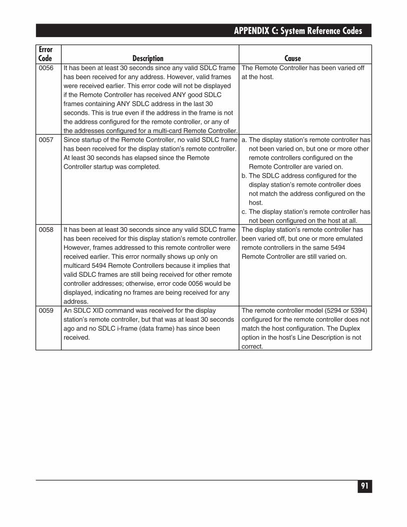
APPENDIX C: System Reference Codes
91
ErrorCode Description Cause0056 It has been at least 30 seconds since any valid SDLC frame The Remote Controller has been varied off
has been received for any address. However, valid frames at the host.were received earlier. This error code will not be displayedif the Remote Controller has received ANY good SDLC frames containing ANY SDLC address in the last 30 seconds. This is true even if the address in the frame is notthe address configured for the remote controller, or any ofthe addresses configured for a multi-card Remote Controller.
0057 Since startup of the Remote Controller, no valid SDLC frame a. The display station’s remote controller hashas been received for the display station’s remote controller. not been varied on, but one or more otherAt least 30 seconds has elapsed since the Remote remote controllers configured on the Controller startup was completed. Remote Controller are varied on.
b. The SDLC address configured for the display station’s remote controller does not match the address configured on thehost.
c. The display station’s remote controller hasnot been configured on the host at all.
0058 It has been at least 30 seconds since any valid SDLC frame The display station’s remote controller hashas been received for this display station’s remote controller. been varied off, but one or more emulatedHowever, frames addressed to this remote controller were remote controllers in the same 5494received earlier. This error normally shows up only on Remote Controller are still varied on.multicard 5494 Remote Controllers because it implies that valid SDLC frames are still being received for other remote controller addresses; otherwise, error code 0056 would be displayed, indicating no frames are being received for any address.
0059 An SDLC XID command was received for the display The remote controller model (5294 or 5394)station’s remote controller, but that was at least 30 seconds configured for the remote controller does notago and no SDLC i-frame (data frame) has since been match the host configuration. The Duplexreceived. option in the host’s Line Description is not
correct.

5494 REMOTE CONTROLLER
92
ErrorCode Description Cause0099 There is no SNA session active for the display station. In many cases, when this error code
Normally, this means that the display station and/or its appears it will be replaced in about 30 remote controller is varied off, and the screen is blank. seconds with one of the following seven
error codes. If this happens, the new error code will be the more specific one, and should be used to determine the problem.If this error code does not get replaced, theproblem may be:
a. The display station has been varied off atthe host, though its remote controller isvaried on.
b. The display station is not configured on the host, or its twinax address (0 through 6, “local station address”) is configured incorrectly.
C.3 Host Support System Reference Codes
SRC Description Explanation0099 Host Support Not Currently Available A key requiring host-system action was pressed, but either
the requested function is not supported or the workstation is not in session with the host system.

APPENDIX C: System Reference Codes
93
C.4 Host Communication Status Codes for Upstream LAN
NOTEPress the ALT key and, while holding it, press the HEX key, followed by the F1 key todisplay these error codes. If no host (screen is blank), these codes may also bedisplayed by pressing ENTER.
In the error codes that follow, the 4th digit of the error code (the “x”) is a digit from 0to 5 that indicates the most advanced stage that the Remote Controller has everreached (since power-up) in its attempts to establish communication with the AS/400.Meanings of the valid values for this digit are:
0: Adapter open failed, and no connect is requested.1: Adapter open failed, connect is requested.2: No connect is requested.3: No TEST received from AS/400.4: No SABME received from AS/400.5: LAN connection to AS/400 established successfully.
SRC Description Cause010X No LAN connection to the AS/400 has been established. The The most probable cause for failure of the
communication status is “adapter open failed, and no connect adapter to open is a bad cable connectionis requested,” meaning that the LAN adapter in the 5494 between the 5494 Remote Controller LANRemote Controller has failed to open, and an operator at an adapter and the LAN segment, MAU, orattached display has requested a “disconnect.” The 5494 hub. Other possible causes are improperly-Remote Controller will periodically re-try to open the LAN seated LAN adapter, permanently failedadapter; but if a retry succeeds, no attempt will be made to LAN adapter, or hardware failure of somecontact the AS/400 until an operator requests a “connect.” other piece of LAN equipment.
011X No LAN connection to the AS/400 has been established. The The most probable cause for failure of the communication status is “adapter open failed, connect is adapter to open is a bad cable connectionrequested,” meaning that the LAN adapter in the 5494 Remote between the 5494 Remote Controller LANController has failed to open, but connection to the AS/400 is adapter and the LAN segment, MAU, orrequested. The 5494 Remote Controller will periodically re-try hub. Other possible causes are improperly-to open the LAN adapter; but if a re-try succeeds, attempts to seated LAN adapter, permanently failedcontact the AS/400 will commence immediately. LAN adapter, or hardware failure of some
other piece of LAN equipment.012X No LAN connection to the AS/400 has been established. The An operator has requested that the 5494
communication status is “no connection is requested,” meaning Remote Controller make no attempts tothat an operator at an attached display has requested a establish communication with the AS/400.‘disconnect,’ canceling attempts to contact the AS/400. Make a “connect” request at any display
attached to the 5494 Remote Controller inorder to re-enable connection attempts.

5494 REMOTE CONTROLLER
94
SRC Description Cause013X Establishment of LAN connection to the AS/400 is not yet The most likely cause for this condition is
complete. The communication status is “no TEST received from that the LAN line description of the AS/400AS/400,” meaning that the 5494 Remote Controller is is varied off. The problem may also beperiodically sending TEST commands to the AS/400, but has caused by configuration errors on the hostnot yet received a TEST in response. or on the controller; verify that all LAN
addresses entered during configurationare correct. Other possible causes are poorconnections to the LAN, or failure of LANcabling, MAU, or hub.
014X Establishment of LAN connection to the AS/400 is not yet The most likely cause for this condition iscomplete. The communication status is “no SABME received that the 5494 Remote Controller’s descrip-from AS/400,” meaning that some communication messages tion on the AS/400 is varied off.have been successfully exchanged between the 5494 RemoteController and the AS/400, but not SABME mode-settingcommand has yet been received from the AS/400.
C.5 LAN Communications System Reference Codes
NOTETo display these error codes, press the ALT key and while holding it depressed, pressthe HEX key, followed by the F2 key. This will display the error codes related to hostcommunication for the LAN gateway. Repeat the same sequence to display error codesspecific to the LAN controller communication.
Cause Code Description Action400000 A connection attempt is already in progress. Wait for a sign-on screen or until an SRC other
than 400000 appears. If attempting to stopcontinuous retries, wait and retry the attempt ina few seconds.
400300 One of the following conditions: If you have selected the wrong AS/400 system,1) You are trying to disconnect from an AS/400 correct the request and retry.system that is not currently connected.2) You are trying to connect to an AS/400 system thatalready has established a connection or is in theprocess of establishing a connection.
400600 The format of the command is not valid. See Chapter 7 for the correct format. Correctand retry.
410100 One of the following XID command length errors was Report this problem to the system operator.detected:1) The I-field is greater than 255 bytes.2) The I-field is less than 29 bytes.3) The XID command length field does not match theI-field length.

APPENDIX C: System Reference Codes
95
Cause Code Description Action410200 An XID contained an unsupported I-field format. There is a system configuration problem.
There is a system configuration problem. Report this problem to the system operator.410300 XID command exchange state indicators are set to There is a system programming error or
“not supported.” configuration problem. Report this problem to thesystem operator.
410400 An XID command did not specify SDLC protocol There is a system programming error or configuration problem. Report this problem to thesystem operator.
410500 An XID3 command specified asynchronous balanced There is a system programming error or mode (ABM) support. configuration problem. Report this problem to the
system operator.410600 An XID3 command specified that an ALS is secondary. There is a system programming error or
configuration problem. Report this problem to thesystem operator.
410700 An XID3 command specified a maximum BTU less than There is a system programming error or 265 bytes. configuration problem. Report this problem to the
system operator.410800 An XID3 command specified an SDLC profile that is not There is a system programming error or
valid. configuration problem. Report this problem to thesystem operator.
410900 The XID3 command specifies a maximum I-frames There is a system programming error or outstanding value that is not valid or supported. configuration problem. Report this problem to the
system operator.411200 The host system reported an error in the XID response Verify the 5494 Remote Controller configuration.
received from the 5494 Remote Controller. There Verify that the serial number field does not start could be a mismatch between the remote controller and with the reserved digits “XI.” If it is correct, therethe host system configuration. could be a configuration problem in the host
system.Pay particular attention to the 5494 Remote Controller CP name and the matching remote CPname field in the host system configuration for the APPC controller.If the configuration is correct, call the system operator and make sure that the APPC controller description for the 5494 Remote Controller is varied on.

5494 REMOTE CONTROLLER
96
Cause Code Description Action4510xx1 An error was detected during communication with an This could be a configuration problem. Verify the
IWS. The error occurred during the XID exchange with IWS configuration, turn the power OFF and backthe IWS. The possible values for xx are: ON at the IWS, then restart the IWS communi-* 80 = Frame length too long cation program.• 40 = Not a format 3 XID• 20 = Length inconsistency between XID and input/
output block (IOB) length• 10 = XID exchange state was non “01”b or “00”b• 08 = Link station role was not “00”b• 04 = Maximum BTU acceptable to IWS was less than
“109”x• 02 = IWS responded to XID with neither an XID nor a
Disconnect command• 01 = XID frame length too short
4523xx The Token-Ring link with the IWS terminated due to Turn the power OFF and back ON at the IWS, receipt of a frame with an ODAI value that is not valid in then restart the IWS communication. If the errorthe transmission header. All sessions for this IWS are persists, it indicates a programming problem interminated. Note: xx is the Token-Ring workstation ID. the IWS.
460000 A frame was received containing an unrecognized If this error occurs frequently, report the error tosession address. the system operator.
460100 A frame was received containing an incorrect format If this error occurs frequently, report the error toidentification (FID) type. the system operator.
460200 A frame was received that was not long enough to If this error occurs frequently, report the error tocontain a full transmission header (TH). the system operator.
460300 A frame was received that was not long enough to If this error occurs frequently, report the error tocontain a full transmission header (TH) and request the system operator.header (RH).
460400 A session control frame was received that was not long If this error occurs frequently, report the error toenough to contain a session control request code. the system operator.
460500 A segmented frame was received. The 5494 Remote If this error occurs frequently, report the error toController does not support segmenting. the system operator.
470100 A BIND request was received with an incorrect ODAI Report the error to the system operator.value in the local form session identifier (LFSID). Thecommunication link to the host system was deactivated.
540010 The Token-Ring adapter in the 5494 Remote Controller The Token-Ring adapter may be failing. Run failed to initialize correctly. extended diagnostics and test all hardware.
540106 The 5494 Remote Controller attempted to attach to the The problem could be caused by a Token-RingToken-Ring (Open) and an adapter open error occurred. speed mismatch between the workstations on the
Token-Ring network. Make sure that all work-stations attached to the Token-Ring network areset to the same Token-Ring speed.

APPENDIX C: System Reference Codes
97
Cause Code Description Action540122 The 5494 Remote Controller detected a Token-Ring There is a problem with the lobe between the
network wire fault. 5494 Remote Controller and the multi-stationaccess unit (MSAU) to which it is connected. TheToken-Ring adapter in the 5494 Remote Controlleris closed, and the remote controller will try toreopen the adapter until the problem between the5494 Remote Controller and MSAU to which the5494 Remote Controller is attached is repaired and the adapter reopens.
540124 The 5494 Remote Controller received a remote 1. Check with the system operator to determine ifcommand from the Token-Ring network. an adapter remove was issued and was valid.
2. If this SRC recurs, the Token-Ring adapter maybe defective. Contact the system administratorand report that a remove command was received.
540125 The Token-Ring network is beaconing because of a Report the problem to the system operator.permanent error on the Token Ring.
540403 (LAN AS/400 Attachment). The 5494 has not If connection to the AS/400 is desired, use the established a LAN connection to the AS/400 because “connect” procedure at any display attached to thean operator at a display attached to the LAN has 5494 Remote Controller to request that the con-requested a disconnect. No connection attempt will be troller begin attempts to establish the LANmade until a connect request is received from an connection.operator.
540404 (LAN AS/400 Attachment) The ALS did not respond to Contact the ALS operator to determine if the ALSthe TEST command sent from the 5494 Remote is operational and configured for the 5494 RemoteController. This indicates that the 5494 Remote Controller. Also, make sure the line is varied on Controller cannot contact the ALS. The 5494 Remote the AS/400 system. Controller will continue to send the TEST command untilthe ALS responds or an operator initiates a disconnect. If the Token-Ring or Ethernet line is varied off:
Have the operator vary on the line. The 5494 Remote Controller should recover without furtheraction.
If the Token-Ring or Ethernet line is varied on: Either the LAN AS/400 Attachment address or the Ethernet frame format configured in the 5494 is incorrect. Reconfigure the 5494 Remote Controller, making sure that the AS/400 Token-Ring or Ethernet address matches the address in the line description at the AS/400 system. For Ethernet configurations, verify that the 5494 Remote Controller frame format matches the frame format configured at the ALS.
If the Token-Ring or Ethernet line cannot be varied on because the AS/400 system is not operational: Wait for it to become operational.

Cause Code Description Action540405 (LAN AS/400 Attachment) The ALS did not respond to Contact that ALS operator to determine if the ALS
the XID3 command sent from the 5494. This indicates is operational and configured for the 5494 Remotethat the 5494 Remote Controller cannot contact the ALS. Controller. Also, make sure the line and APPCThe 5494 Remote Controller will continue to send the controller descriptions are varied on at the AS/400XID3 command until the ALS responds or an operator system.initiates a disconnect.
If the APPC controller is not varied on: Vary on the 5494 Remote Controller. The Controller should recover without any further action.
If the APPC controller cannot be varied on because the AS/400 system is not operational: Wait for it to become operational.
540406 (LAN AS/400 Attachment) Adapter open error. There For Token-Ring, make sure that all workstationswas a problem when the 5494 Remote Controller attached to the ring are set to the same speed.attempted to attach to the LAN. The Controller will try again to attach to the LAN. For Token-Ring, the problem If the 5494 Remote Controller cannot attach to thecould be caused by a speed mismatch between the LAN after retrying, note the following sense-byteworkstations on the ring. information and then refer to the IBM Token-Ring
Network Problem Determination guide or instructions on correcting the error. Verify that the cabling is connected correctly.
Note: To obtain sense data, press the right arrow key on the 5494 Remote Controller keypad when this SRC is displayed.
Token-Ring Sense Bytes:
1100 Lobe media function failure2600 Physical insertion ring failure2700 Physical insertion ring failure ring
beaconing2A00 Physical insertion error timeout2D00 No monitor detected3200 Address verification signal loss3500 Address verification timeout3600 Address verification ring failure3700 Address verification ring beaconing3800 Address verification duplicate node address3A00 Address verification remove received4200 Ring poll signal loss4500 Ring poll timeout4600 Ring poll ring failure4700 Ring poll beaconing
5494 REMOTE CONTROLLER
98

APPENDIX C: System Reference Codes
99
Cause Code Description Action4A00 Ring poll remove received5700 Request parameter ring failure5900 Request parameter request5A00 Request parameter remove received
Ethernet Sense Bytes:
3300 Unable to transmit3800 Address verification duplicate node address
540422 (Token-Ring AS/400 Attachment) The 5494 Remote Record the symptom wire fault, and then refer toController detected a Token-Ring network wire fault. the IBM Token-Ring Network Problem Deter-There is a problem with the lobe between the 5494 mination guide to repair the problem.Remote Controller and the multistation access unit (MSAU) to which it is connected.
The Token-Ring adapter in the 5494 Remote Controlleris closed. The Controller will continue to try to reopen theadapter until a Disconnect command is received from a5494 Remote Controller operator or until the problem isrepaired and the adapter reopens.
540424 (Token-Ring AS/400 Attachment) The 5494 Remote 1. Check with the Token Ring network ad-Controller received a remove command from the ministrator to determine if an adapter remove wasToken-Ring network. was issued and was valid.
2. If the Token-Ring network administrator or network service representative did not issue an adapter remove, go to the operator panel and retry the Adapter Open command from the 5494 Remote Controller operator panel by pressing Req. typing 230, then pressing Enter.3. If this SRC reoccurs, the Token-Ring adapter inthe 5494 Remote Controller may be defective. Run extended diagnostics and test all hardware.
If the extended diagnostics did not detect a problem, contact the Token-Ring network administrator and report that a remove command was received.
540425 (Token-Ring AS/400 Attachment) The Token-Ring 1. Record that the Token-Ring is beaconing.network is beaconing due to a permanent error on the 2. Refer to the IBM Token-Ring Network Problemring. Determination guide and use the beaconing as the
symptom.

5494 REMOTE CONTROLLER
100
Appendix D. Connecting TwinaxCards
The material in this appendix is directed to users familiar with the strapping jumpers used to combine twinaxcards into pairs for use in PC394A-R2 and PC394A-R3 Remote Controllers. Every 8-device twinax card has an 8-pin connector located at the top of the board. This connector should always be connected to either a single-ended or a double-ended jumper plug, or to one end of a double-ended jumper. In the PC394A-R2 andPC394A-R3 controllers, the double-ended type of jumper was used to interconnect pairs of twinax cards thatwere to be configured as 3-port 5394 controllers. In the 5494 Remote Controller, combining of cards to beconfigured as multi-card controllers is done through software, and the use of the double-ended jumpers is nolonger required. The same is true of older controllers that have been upgraded to use 5494 software. If yourcontroller contains any 8-device twinax cards, please note the following points:
1. We strongly recommend that every 8-device twinax card in a 5494 Remote Controller be fitted with thesingle-ended type of jumper. All new 8-device twinax cards are shipped with this type of jumper in place.Your dealer can supply you with jumper plugs if those shipped with your cards are not available. Rememberthat an 8-device card fitted with the single-ended jumper must have switch 6 in its DIP-switch block set tothe OFF position (away from the number 6).
2. If you choose to leave a pair of 8-device cards strapped together with a double-ended jumper, that pair ofcards should be used only as a 2-card 5394. The double-ended jumper electrically disables the top port onthe second card of the pair, making the card unsuitable for use as anything but the second card of a 5394controller emulation.
3. If you do plan to use a jumpered pair of cards as a 2-card 5394, remember that the two cards must still besoftware configured to emulate a 2-card controller. 5494 software ignores the double-ended jumper, andwill treat the two cards as two single-card controllers unless software configuration is done the same way itwould be done for cards having single-ended jumper plugs.
4. You can check the main menu of the 5494 online configuration program to determine whether yourcontroller includes any hardware-jumpered pairs of twinax cards. Suppose for example that the menuscreen includes the following lines:
1. CARD 1 5494/1 82. CARD 2 5494/1 8 a3. CARD 3 5494/1 8 b4. CARD 4 5494/1 8
This tells you that the controller contains four 8-device twinax cards, each configured in software as a single-card 5494. However, the “a” and “b” at the right ends of lines 2 and 3 indicate that cards 2 and 3 are the firstand second cards in a jumped pair. As long as the double-ended jumper connecting those two cards remains inplace, the top port of card 3 will not work. You should replace the double-ended jumper with two single-endedplugs, and turn off switch 6 on each of the two cards. This will align the hardware configuration with thesoftware configuration.

APPENDIX E: Concurrent Host Attachment
101
Appendix E. Concurrent HostAttachment
E.1 OverviewThe Remote Controller can be configured to communicate with up to four AS/400 systems at the same timeover one physical link. Display stations on the Remote Controller can switch from one AS/400 system toanother without starting a pass-through session. Connecting to multiple AS/400 hosts at the same time is madepossible by using the routing capabilities of an APPN network. An APPN connection between AS/400 hostsshould be set up and verified before configuring concurrent host attachment. Concurrent host attachment mayalso be referred to as “Multihost” functionality.
E.2 Verifying the APPN Connection Between SystemsAn APPN link should exist between the primary and secondary AS/400 hosts before configuring concurrenthost attachment. One way to see if this link exists is to use the strpasthr command. The target system namefollows the strpasthr command on the command line. If pass-through from the primary to each of thesecondary hosts works, then the APPN connections exist and will carry concurrent host attachment traffic.
E.3 Configuring Concurrent Host AttachmentThe AS/400 that directly connects to the Remote Controller over the physical link is designated as the PrimaryAS/400 host. All concurrent host attachment traffic is routed through this host. Since the Primary AS/400sends data from the Remote Controller to the secondary hosts, the Primary AS/400 should be configured as anAPPN Network node. The secondary AS/400 systems can be configured as either APPN Network nodes for Endnodes. The Remote Controller fields that need to be filled in will appear in the Network InformationConfiguration screen like this:
The Primary AS/400 is identified in the Remote Controller configuration screen as H1:1. The field H1:1through H1:4 describe the Remote Controller’s connection to the Primary host. Similarly, fields contained inH2, H3, and H4 refer to the secondary AS/400s. The last field on each concurrent host attachment line shouldcontain the QRMTWSC mode name.
H1:1-> _______ H1:2-> ________ H1:3->_________ H1:4->QRMTWSC
H2:1-> _______ H2:2-> ________ H2:3->_________ H2:4->QRMTWSC
H3:1-> _______ H3:2-> ________ H3:3->_________ H3:4->QRMTWSC
H4:1-> _______ H4:2-> ________ H4:3->_________ H4:4->QRMTWSC
5494 REMOTE CONTROLLER
102
E.4 Switching Between AS/400 SystemsEach time the Remote Controller is powered up, all powered-on displays will connect to the Primary AS/400. Inorder to switch between AS/400 systems, do the following:
1 When you want to switch to a new AS/400, sign off of your current host.
2 Press the System Request key sequence on the display. You may see the default host identifier H1 appear onthe System Request Line if you currently have no session with the host.
3 Choose the host you want to go to. This is done by entering H1 for the first host, H2 for the second host,H3 for the third host, and H4 for the fourth host.
For example, to go to the second configured host, enter H2 in the first two characters of the SystemRequest line:
H2
_ _ _ _ _ _ _ _ _ _ _ _ _ _ _ _ _ _ _ _ _ _ _ _ _ _ _ _ _ _ _ _ _ _ _ _ _ _ _ _
4 Hit Enter.
If you have correctly entered the host switch command, within a few seconds the Remote Controller willswitch your display session to the host you have chosen. If the command is incorrectly entered, the RemoteController will forward the request to the AS/400. You may not see an error on your screen when thishappens if the display has a login screen.
E.5 PrintingWhen a Remote Controller is configured for concurrent host attachment, and the user is on the PrimaryAS/400, the user may elect to print to a printer that is attached to the Remote Controller. When a user islogged onto the Secondary AS/400, printing to printers that are attached to the Remote Controller is notsupported. Printer sharing is also not supported.
1000 Park Drive • Lawrence, PA 15055-1018 • 724-746-5500 • Fax 724-746-0746
© Copyright 1998. Black Box Corporation. All rights reserved.