pázmány péter catholic university faculty of information technology and bionics see-and-avoid...
TRANSCRIPT

Pázmány Péter Catholic University Faculty of Information Technology and Bionics
See-and-Avoid System for UAV with Five Miniature Cameras
Tamás Zsedrovits†, Ákos Zarándy*†, Zoltán Nagy*†, Bálint Vanek*, András Kiss*†, Máté Németh*†
†Pázmány Péter Catholic University, Faculty of Information Technology and Bionics, Budapest, Hungary,*Computer and Automation Research Institute of the Hungarian Academy of Sciences (MTA SZTAKI)
Budapest, Hungary
EESTEC HIT 01/29/2014
Pázmány Péter Catholic University Faculty of Information Technology and Bionics
Outline• Goals• System requirements• Vision system architecture• Many core processor array implementation• Algorithms
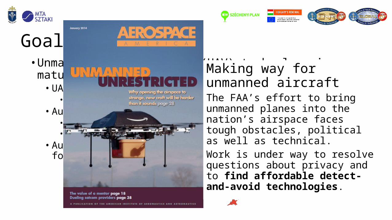
• Unmanned Aerial Vehicle (UAV) technology is maturing• UAVs are ready for autonomous missions technically
• Surveillance tasks • Autonomous missions are not authorized
• Missing redundancy • Missing collision avoidance device
• Automatic collision avoidance device is needed even for remotely piloted UAVs*
Goals
Making way for unmanned aircraftThe FAA’s effort to bring unmanned planes into the nation’s airspace faces tough obstacles, political as well as technical.Work is under way to resolve questions about privacy and to find affordable detect-and-avoid technologies.

Collision avoidance devices• Radar based
• Applied on large airliners (Airbus)
• Radar and vision• Applied on large remotely piloted UAVs (predator)
• Transponder based• TCAS, ADS-B (all manned aircrafts and larger UAVs)
• Vision only • Currently developed (small UAVs)
• Basic requirements• Equivalent safety• Probabilities of collision < 10-11 per flight hour• Layered approach
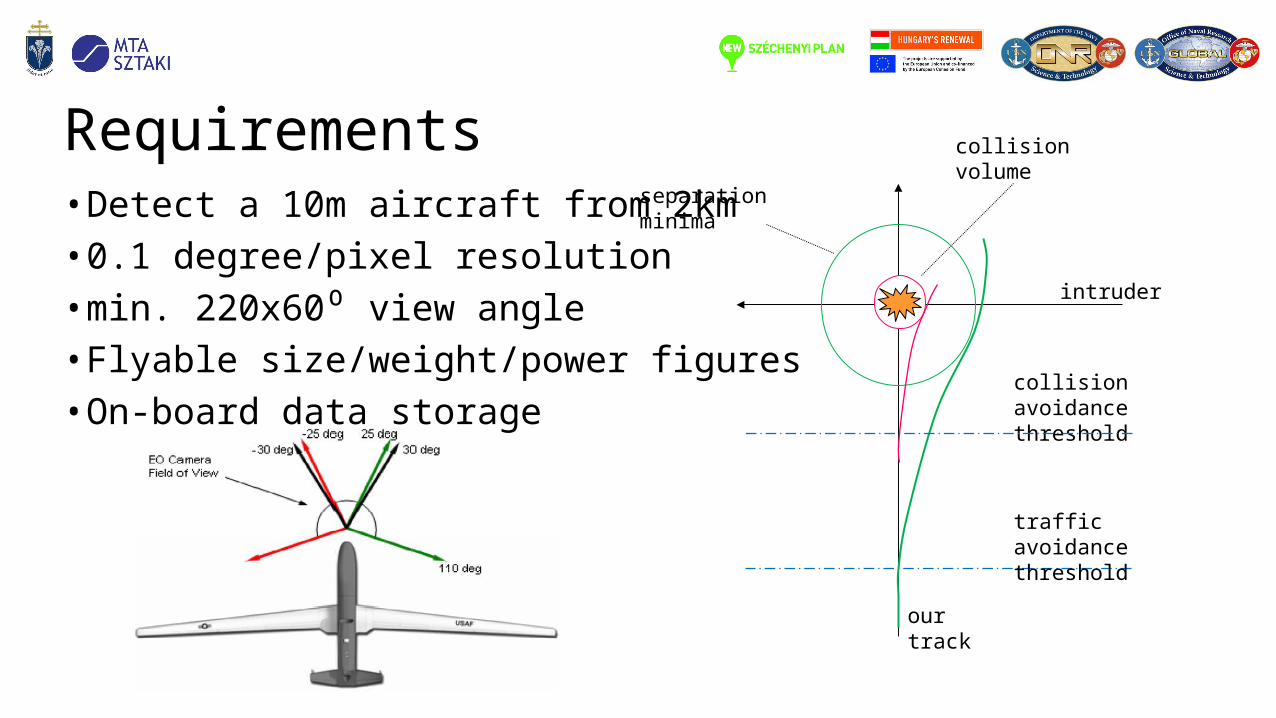
Requirements• Detect a 10m aircraft from 2km• 0.1 degree/pixel resolution• min. 220x60⁰ view angle• Flyable size/weight/power figures• On-board data storage
intruder
collision volume
separation minima
collision avoidance threshold
traffic avoidance threshold
our track
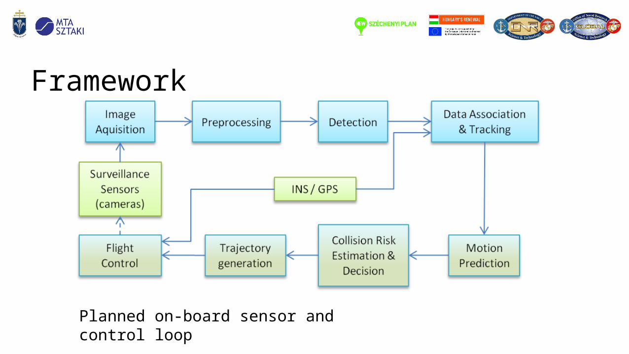
Framework
Planned on-board sensor and control loop
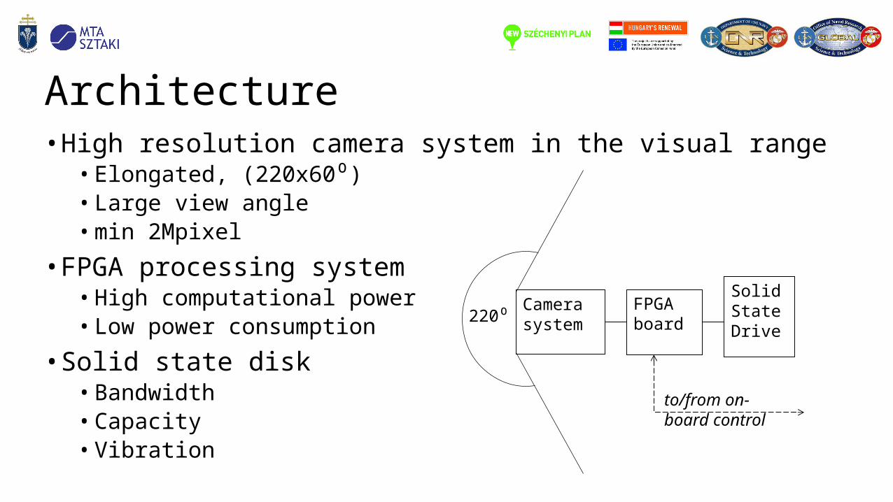
Architecture• High resolution camera system in the visual range
• Elongated, (220x60⁰)• Large view angle• min 2Mpixel
• FPGA processing system • High computational power• Low power consumption
• Solid state disk• Bandwidth• Capacity• Vibration
Solid State Drive
FPGA board
Camera system
to/from on-board control
220⁰

Camera selection• Single camera with wide angle optics
• Easy from architectural, algorithmic, and processing side• Low distortion, ultra wide view angle optics are bulky
• 3 pieces of C-mount cameras• Good image quality• Relatively large size, volume, and power (1kg, 10W)• High speed serial I/O (USB, Gige, fire-wire) difficult to connect to embedded systems
• 5 pieces of miniature cameras (M12 lens)• Max 1.2 megapixel with global shutter• 50g, 200mW• Poorer image quality
• Micro cameras• Very advantages size/weight/power figures• Rolling shutter only
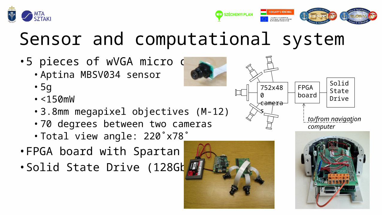
Sensor and computational system• 5 pieces of wVGA micro cameras
• Aptina MBSV034 sensor• 5g• <150mW• 3.8mm megapixel objectives (M-12)• 70 degrees between two cameras• Total view angle: 220˚x78˚
• FPGA board with Spartan 6 FPGA• Solid State Drive (128Gbyte)
Solid State Drive
FPGA board
752x480 cameras
to/from navigation computer
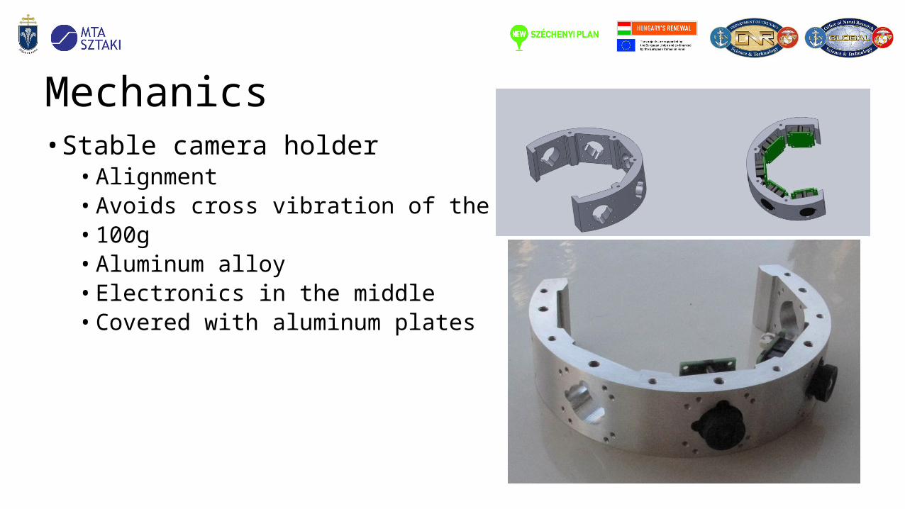
Mechanics• Stable camera holder
• Alignment• Avoids cross vibration of the cameras• 100g • Aluminum alloy• Electronics in the middle• Covered with aluminum plates
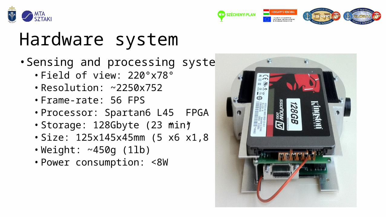
Hardware system• Sensing and processing system
• Field of view: 220°x78°• Resolution: ~2250x752• Frame-rate: 56 FPS• Processor: Spartan6 L45 FPGA • Storage: 128Gbyte (23 min)• Size: 125x145x45mm (5”x6”x1,8”)• Weight: ~450g (1lb)• Power consumption: <8W
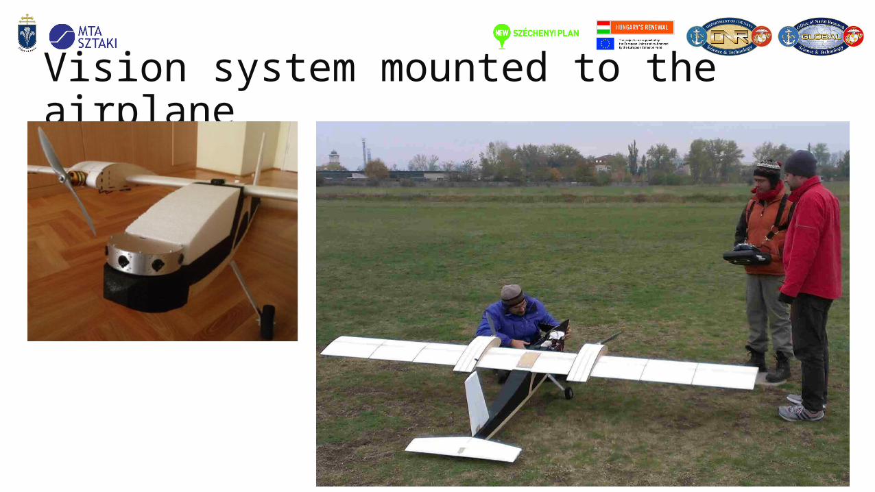
Vision system mounted to the airplane
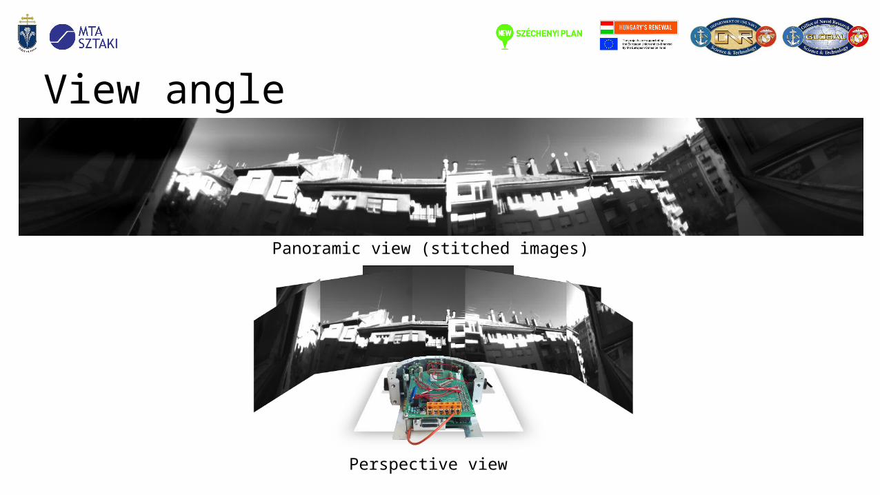
View angle
Panoramic view (stitched images)
Perspective view
Many-core processor arrays implemented in FPGA
• FPGA chips have the largest computational capability nowadays• In affordable medium sized FPGAs:
• Over 200 DSP cores • 200 memory blocks• 500 IO pins• Low power consumption• Special purpose processor arrays
• How to utilize this performance?• Many-core architectures• Specially optimized data and control paths• Distributed control units
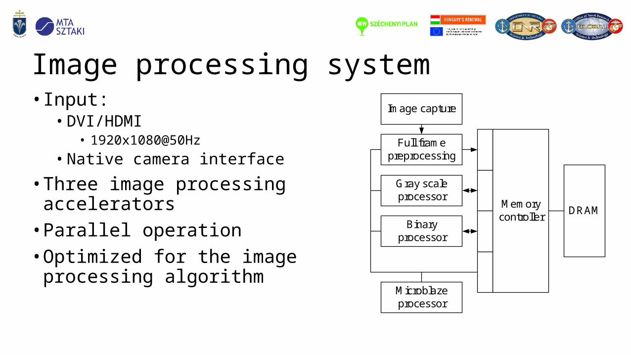
Image processing system
Memorycontroller
DRAM
Microblazeprocessor
Image capture
Full framepreprocessing
Gray scaleprocessor
Binaryprocessor
• Input:• DVI/HDMI
• 1920x1080@50Hz• Native camera interface
• Three image processing accelerators
• Parallel operation• Optimized for the image processing
algorithm
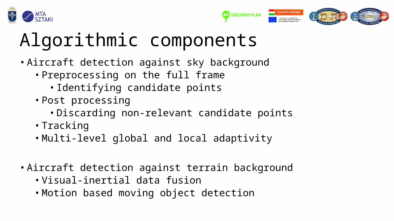
Algorithmic components • Aircraft detection against sky background
• Preprocessing on the full frame• Identifying candidate points
• Post processing• Discarding non-relevant candidate points
• Tracking • Multi-level global and local adaptivity
• Aircraft detection against terrain background• Visual-inertial data fusion• Motion based moving object detection
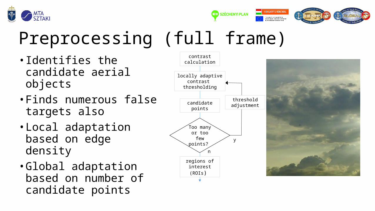
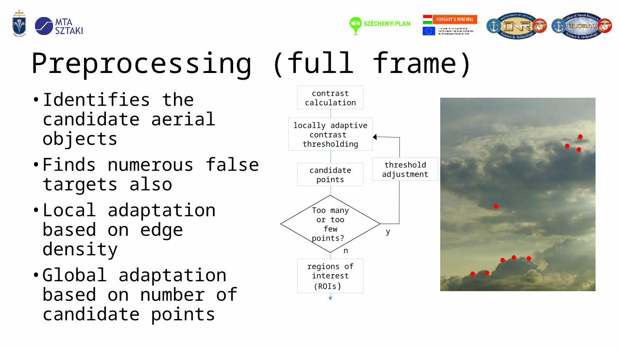
Preprocessing (full frame)• Identifies the candidate aerial
objects• Finds numerous false targets
also• Local adaptation based on
edge density• Global adaptation based on
number of candidate points
contrast calculation
locally adaptive contrast thresholding
candidate points
regions of interest (ROIs)
threshold adjustment
Too many or too few points? y
n
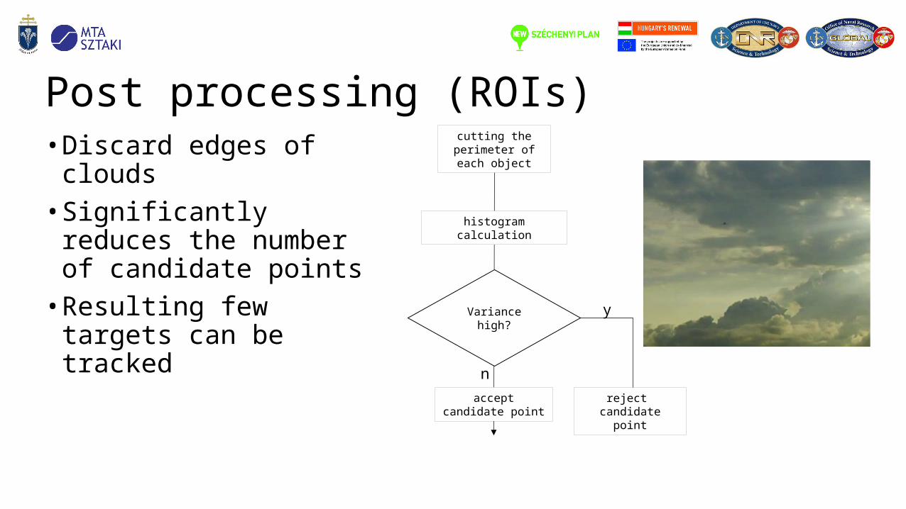
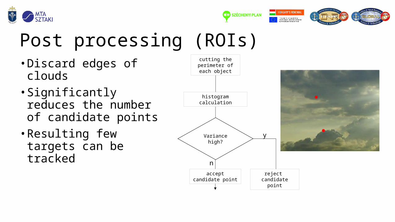
Post processing (ROIs)• Discard edges of clouds• Significantly reduces the
number of candidate points• Resulting few targets can be
tracked
n
cutting the perimeter of each object
histogram calculation
accept candidate point
Variance high?
reject candidate point
y
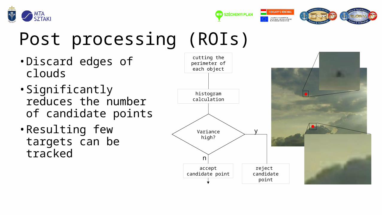
Post processing (ROIs)• Discard edges of clouds• Significantly reduces the
number of candidate points• Resulting few targets can be
tracked
n
cutting the perimeter of each object
histogram calculation
accept candidate point
Variance high?
reject candidate point
y
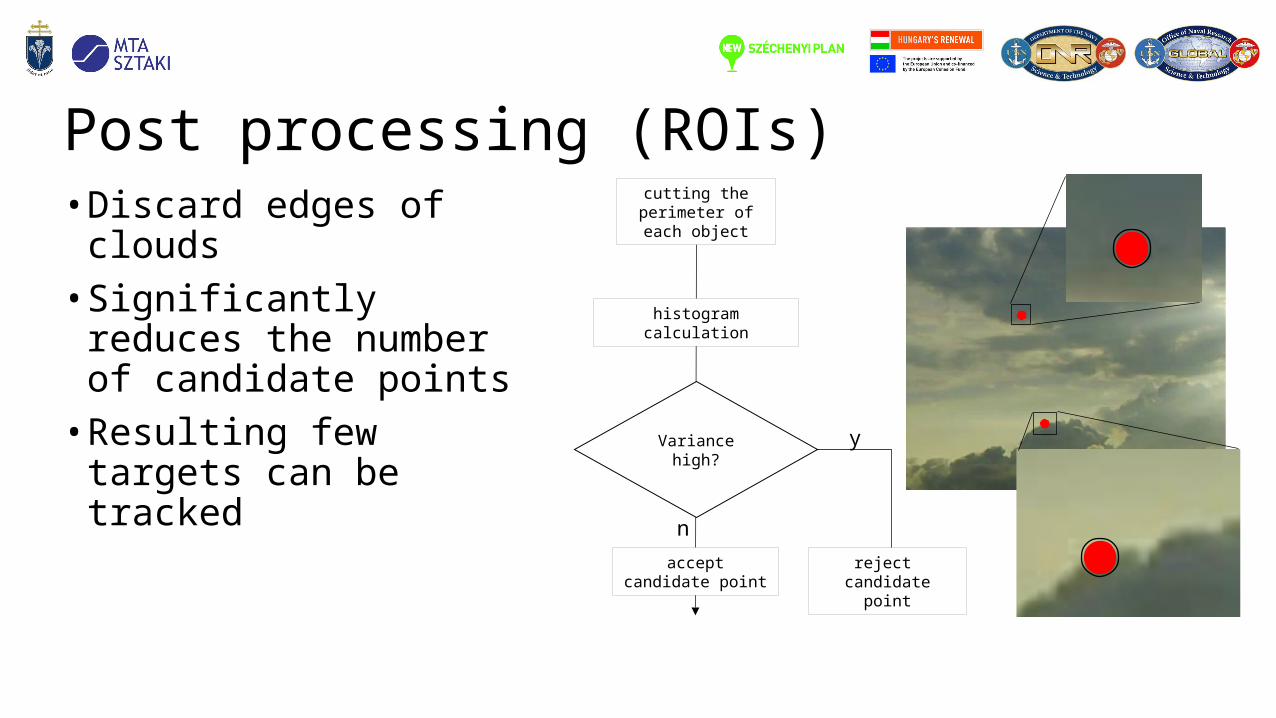
Post processing (ROIs)• Discard edges of clouds• Significantly reduces the
number of candidate points• Resulting few targets can be
tracked
n
cutting the perimeter of each object
histogram calculation
accept candidate point
Variance high?
reject candidate point
y
Post processing (ROIs)• Discard edges of clouds• Significantly reduces the
number of candidate points• Resulting few targets can be
tracked
n
cutting the perimeter of each object
histogram calculation
accept candidate point
Variance high?
reject candidate point
y
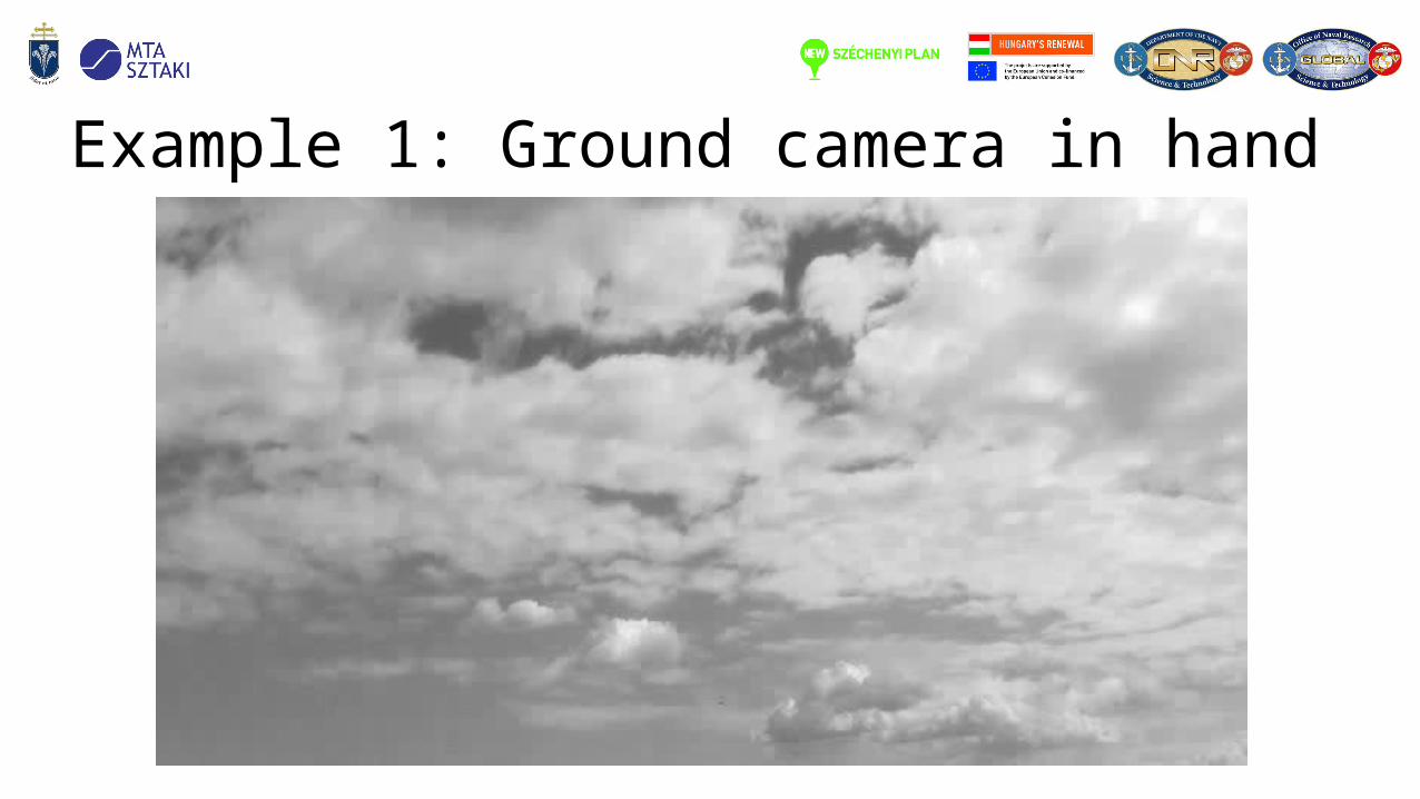
Example 1: Ground camera in hand
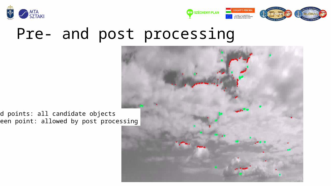
Pre- and post processing
Red points: all candidate objectsGreen point: allowed by post processing
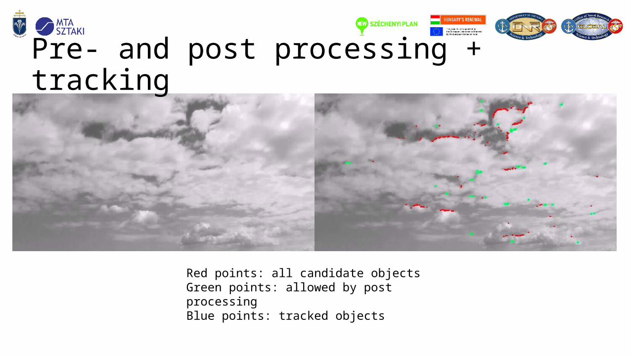
Pre- and post processing + tracking
Red points: all candidate objectsGreen points: allowed by post processingBlue points: tracked objects
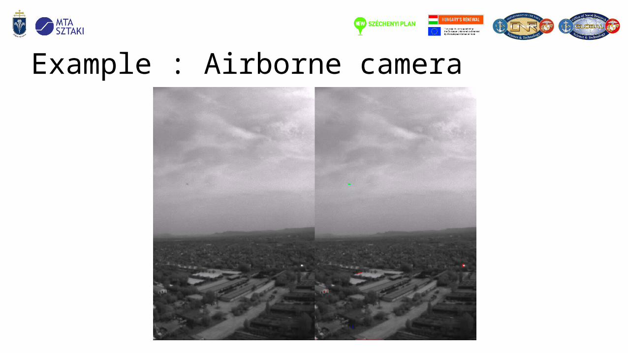
Example : Airborne camera

Navigation aid• UAV was equipped with INS and cameras
• Attitude was calculated from the INS data (blue)
• Attitude was calculated from 5 point (red) and 8 point (magenta) algorithms
• Visual-navigation data fusion development is going on
615 620 625 630 635-200
-150
-100
-50
0
50
100
150
200Absolute yaw angles
Time [s]
[
deg]
615 620 625 630 635-100
-80
-60
-40
-20
0
20
40
60
80Absolute roll angles
Time [s]
[d
eg]
615 620 625 630 635-30
-20
-10
0
10
20
30
40
50
60Absolute pitch angles
Time [s]
[d
eg]
Conclusion• Vision system is under development• Currently
• We are replacing the FPGA board• Finalizing the implementation of the image processing subsystem• Fusion of visual and navigation algorithms• Replacing the wVGA cameras with 1.2 megapixel ones
• Expecting the system completion by the end of the year
Thank you for your attention!
• The ONR Grant (Number: N62909-10-1-7081) is greatly acknowledged.
• The support of the grants TÁMOP-4.2.1.B-11/2/KMR-2011-0002 and TÁMOP-4.2.2/B-10/1-2010-0014 is gratefully acknowledged.
• The financial support provided jointly by the Hungarian State, the European Union and the European Social Fund through the grant TÁMOP 4.2.4.A/1-11-1-2012-0001 is gratefully acknowledged.
FPGA, many-core processing and UAV group
Ákos Zarándy Péter Szolgay
András Radványi
Zoltán Nagy
András Kiss
Pencz Borbála
Németh Máté