pattern lang for adc firmware - the hillside group · 3.2.6 related patterns 7 3.3 periodic...
TRANSCRIPT
15th American Conference on Pattern Languages of Programming (PLoP) 2008
Copyright 2007 by Schlumberger Technology Corporation. All rights reserved.
A Pattern Language for Developing Analog to Digital Converter Data Sampling
Firmware
Sachin Bammi, Peter Swinburne and Adefeyike Odutayo
Schlumberger Technology Corporation, Sugar Land, TX, USA
Abstract:
Analog to digital converters (ADC) are widely used real-time data acquisition systems. This paper presents a pattern language for sampling data from analog to digital converters (ADC) by presenting commonly used best practices and providing advice on avoiding specific pitfalls in designing ADC data sampling/acquisition firmware. From the classification presented in the paper a user can potentially come up with 15 designs to sample ADCs. The paper first presents seven core patterns followed by three composite ones that the authors have seen being successfully applied in their domain and work experience.
15th American Conference on Pattern Languages of Programming (PLoP) 2008 A pattern language for developing Analog to Digital Converter data sampling firmware
Copyright 2008 by Schlumberger Technology Corporation. All rights reserved. 2
Table of Contents
1 INTRODUCTION 4
2 INTENDED AUDIENCE AND SCOPE 5
3 ATOMIC ADC DATA SAMPLING PATTERNS 6
3.1 Discrete Sampling 6 3.1.1 Context 6 3.1.2 Problem 6 3.1.3 Forces 6 3.1.4 Solution 6 3.1.5 Resulting Context 6 3.1.6 Related Patterns 6
3.2 Simultaneous Sampling 7 3.2.1 Context 7 3.2.2 Problem 7 3.2.3 Forces 7 3.2.4 Solution 7 3.2.5 Resulting Context 7 3.2.6 Related Patterns 7
3.3 Periodic Sampling 7 3.3.1 Context 7 3.3.2 Problem 7 3.3.3 Forces 7 3.3.4 Solution 7 3.3.5 Resulting Context 8 3.3.6 Related Patterns 8
3.4 Quasi-Periodic Sampling 8 3.4.1 Context 8 3.4.2 Problem 8 3.4.3 Forces 8 3.4.4 Solution 8 3.4.5 Resulting Context 8 3.4.6 Related Patterns 8
3.5 Non-Periodic or Event-Driven Sampling 8 3.5.1 Context 8 3.5.2 Problem 8 3.5.3 Forces 9 3.5.4 Solution 9 3.5.5 Resulting Context 9 3.5.6 Related Patterns 9
3.6 Sequential Sampling 9 3.6.1 Context 9 3.6.2 Problem 9
15th American Conference on Pattern Languages of Programming (PLoP) 2008 A pattern language for developing Analog to Digital Converter data sampling firmware
Copyright 2008 by Schlumberger Technology Corporation. All rights reserved. 3
3.6.3 Forces 9 3.6.4 Solution 9 3.6.5 Resulting Context 10 3.6.6 Related Patterns 10
3.7 Table Driven Sampling 10 3.7.1 Context 10 3.7.2 Problem 10 3.7.3 Forces 10 3.7.4 Solution 10 3.7.5 Resulting Context 10 3.7.6 Related Patterns 11
4 COMPOSITE ADC DATA SAMPLING PATTERNS 11
4.1 Discrete Periodic Sequential Sampling Pattern 11 4.1.1 Context 11 4.1.2 Problem 11 4.1.3 Forces 11 4.1.4 Solution 11 4.1.5 Resulting Context 15 4.1.6 Related Patterns 16 4.1.7 Known Uses 16
4.2 Discrete Periodic Table Driven Sampling Pattern 16 4.2.1 Context 16 4.2.2 Problem 16 4.2.3 Forces 16 4.2.4 Solution 17 4.2.5 Resulting Context 18 4.2.6 Related Patterns 18 4.2.7 Known Uses 18
4.3 Quasi-Periodic Table Driven Sampling Pattern 18 4.3.1 Context 18 4.3.2 Problem 18 4.3.3 Forces 19 4.3.4 Solution 19 4.3.5 Resulting Context 20 4.3.6 Related Patterns 21 4.3.7 Known Uses 21
5 THE HARDWARE ANGLE 21
6 PATTERN THUMBNAILS 21
7 ACKNOWLEDGMENTS 22
8 REFERENCES 22

15th American Conference on Pattern Languages of Programming (PLoP) 2008 A pattern language for developing Analog to Digital Converter data sampling firmware
Copyright 2008 by Schlumberger Technology Corporation. All rights reserved. 4
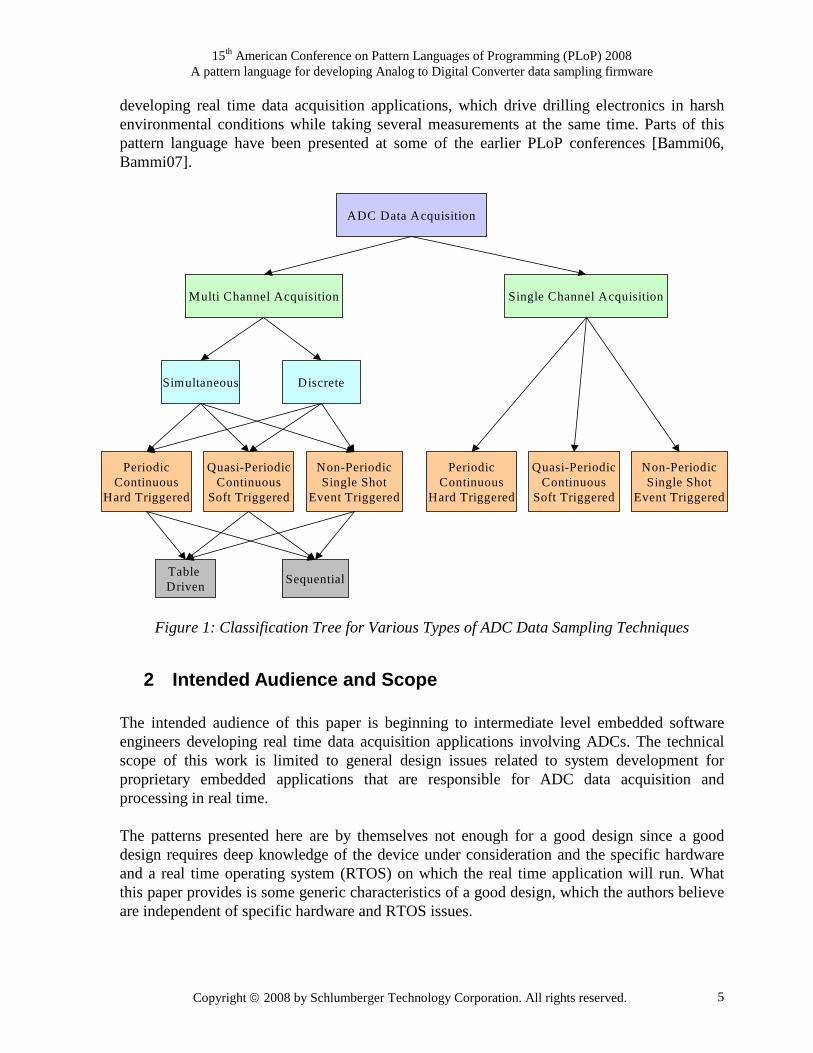
1 Introduction A real time data acquisition system may at times need to acquire data from an analog signal and convert the signal to a digital format. The hardware device that performs this conversion is called the analog to digital converter (ADC). The ADC converts analog signals to discrete digital numbers. The digital output may be in binary or two’s complement. ADCs are used virtually in all applications where an analog signal has to be processed, stored, or transported in digital form. ADC implementation ranges from direct conversion ADCs to Sigma-Delta ADCs. There are several types of ADCs available, each satisfying a particular purpose [WIKI07, Staller05]. As such, the choice of the type of ADC is dependent on application requirements. Data acquisition through an ADC can be divided into several categories. The first level of classification is based on the number of analog signals being sampled. If two or more analog signals are being sampled then the question arises if they are all sampled at once (simultaneous) or sequentially (i.e. one at a time). In either of these cases the periodicity (if any) is the next basis of distinguishing between the various ADC sampling techniques. The periodicity at which the analog signals are being sampled (simultaneously or discreetly) can be fixed, quasi-periodic or non-periodic. When the periodicity is fixed, a hardware device such as a timer is usually used to triggering the ADC, while a quasi-periodic sampling is usually soft triggered. The non-periodic triggering of the ADC is typically random usually, as a result of some external event. Both multi-channel and single-channel ADC sampling techniques can have the aforementioned sub-classifications based on the periodicity of the sampling. Finally at the firmware implementation level a sequential or table driven sampling approach can be used to distinguish between applied ADC sampling techniques. Figure 1 summarizes the above classifications. Based on Figure 1, there are seven core basic patterns that are talked about in section 3. These seven patterns for a generative pattern language which can be used to develop 15 composite design patterns as explained next. The number of patterns that can be generated for multi-channel acquisition are 2 (simultaneous or discreet) x 3 (Periodic or Quasi-Periodic or Non-Periodic) x 2 (Table driven or Sequential). This gives us 12 possible multi channel ADC sampling design patterns. Similarly the number of patterns that can be generated for single-channel acquisition are: 1 (only one way to do it) x 3 (Periodic or Quasi-Periodic or Non-Periodic) x 1 (only one way to do it) = 3 possible single channel ADC sampling design patterns. Hence the pattern language that we are presenting in this paper is a set of the above possible design patterns (12 + 3 = 15) that a reader/user can potentially choose from. What we describe in the paper are 3 of these 15 that we have seen most commonly in our domain and work experience in section 4. The patterns presented in this paper aim at providing general architecture specific guidelines for developing the firmware for a real time data acquisition with an ADC. The authors recommend keeping them in mind while using other published references [Kalinsky03, Kalinsky06, Bammi06, Bammi07] which may not necessarily be focusing just on ADCs. These patterns are elements of a pattern language being developed by the authors for
15th American Conference on Pattern Languages of Programming (PLoP) 2008 A pattern language for developing Analog to Digital Converter data sampling firmware
Copyright 2008 by Schlumberger Technology Corporation. All rights reserved. 5
developing real time data acquisition applications, which drive drilling electronics in harsh environmental conditions while taking several measurements at the same time. Parts of this pattern language have been presented at some of the earlier PLoP conferences [Bammi06, Bammi07].
Figure 1: Classification Tree for Various Types of ADC Data Sampling Techniques
2 Intended Audience and Scope The intended audience of this paper is beginning to intermediate level embedded software engineers developing real time data acquisition applications involving ADCs. The technical scope of this work is limited to general design issues related to system development for proprietary embedded applications that are responsible for ADC data acquisition and processing in real time. The patterns presented here are by themselves not enough for a good design since a good design requires deep knowledge of the device under consideration and the specific hardware and a real time operating system (RTOS) on which the real time application will run. What this paper provides is some generic characteristics of a good design, which the authors believe are independent of specific hardware and RTOS issues.
ADC Data Acquisition
Multi Channel Acquisition Single Channel Acquisition
Simultaneous Discrete
PeriodicContinuous
Hard Triggered
Quasi-PeriodicContinuous
Soft Triggered
Non-PeriodicSingle Shot
Event Triggered
Table Driven
Sequential
PeriodicContinuous
Hard Triggered
Quasi-PeriodicContinuous
Soft Triggered
Non-PeriodicSingle Shot
Event Triggered
15th American Conference on Pattern Languages of Programming (PLoP) 2008 A pattern language for developing Analog to Digital Converter data sampling firmware
Copyright 2008 by Schlumberger Technology Corporation. All rights reserved. 6
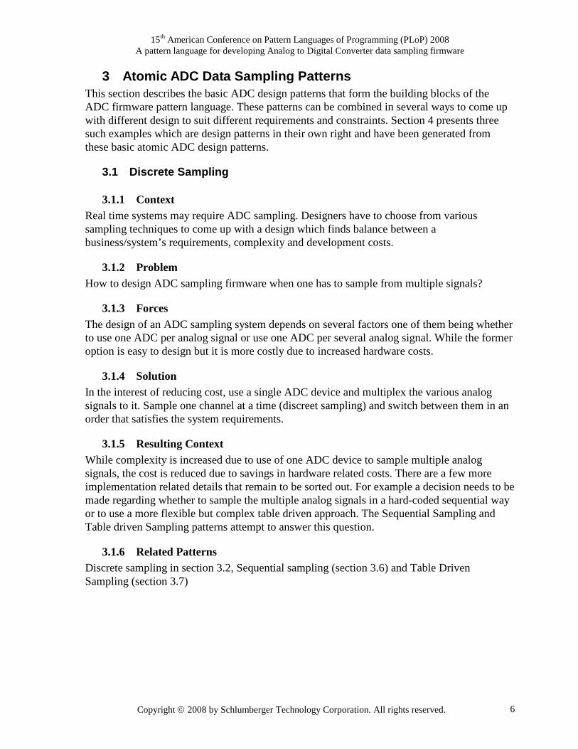
3 Atomic ADC Data Sampling Patterns This section describes the basic ADC design patterns that form the building blocks of the ADC firmware pattern language. These patterns can be combined in several ways to come up with different design to suit different requirements and constraints. Section 4 presents three such examples which are design patterns in their own right and have been generated from these basic atomic ADC design patterns.
3.1 Discrete Sampling
3.1.1 Context Real time systems may require ADC sampling. Designers have to choose from various sampling techniques to come up with a design which finds balance between a business/system’s requirements, complexity and development costs.
3.1.2 Problem How to design ADC sampling firmware when one has to sample from multiple signals?
3.1.3 Forces The design of an ADC sampling system depends on several factors one of them being whether to use one ADC per analog signal or use one ADC per several analog signal. While the former option is easy to design but it is more costly due to increased hardware costs.
3.1.4 Solution In the interest of reducing cost, use a single ADC device and multiplex the various analog signals to it. Sample one channel at a time (discreet sampling) and switch between them in an order that satisfies the system requirements.
3.1.5 Resulting Context While complexity is increased due to use of one ADC device to sample multiple analog signals, the cost is reduced due to savings in hardware related costs. There are a few more implementation related details that remain to be sorted out. For example a decision needs to be made regarding whether to sample the multiple analog signals in a hard-coded sequential way or to use a more flexible but complex table driven approach. The Sequential Sampling and Table driven Sampling patterns attempt to answer this question.
3.1.6 Related Patterns Discrete sampling in section 3.2, Sequential sampling (section 3.6) and Table Driven Sampling (section 3.7)

15th American Conference on Pattern Languages of Programming (PLoP) 2008 A pattern language for developing Analog to Digital Converter data sampling firmware
Copyright 2008 by Schlumberger Technology Corporation. All rights reserved. 7
3.2 Simultaneous Sampling
3.2.1 Context Real time systems may require ADC sampling. Designers have to choose from various sampling techniques to come up with a design which finds balance between business requirements, complexity and development costs.
3.2.2 Problem How to design ADC sampling firmware when one has to sample from multiple analog signals?
3.2.3 Forces The design of an ADC sampling system depends on several factors one of them being whether to use one ADC per analog signal or use one ADC per several analog signals. While the former option is easy to design but it is more costly due to increased hardware costs.
3.2.4 Solution In the interest of reducing complexity, use one ADC device per signal that needs to be sampled. This way all the analog signals can be sampled simultaneously.
3.2.5 Resulting Context The simultaneous sampling design while being more costly is straight forward to implement and reduces the sampling time.
3.2.6 Related Patterns Sequential sampling in Section 3.1
3.3 Periodic Sampling
3.3.1 Context Real time systems may require ADC sampling. Designers have to choose from various sampling techniques to come up with a design which finds balance between business requirements, complexity and development costs.
3.3.2 Problem How to choose the periodicity of sampling while designing ADC sampling firmware?
3.3.3 Forces Sometimes the timing constraints on the rate of sampling are very strict and may require sampling to occur with a certain guaranteed interval of time.
3.3.4 Solution Use hardware based interrupt triggering for ADC sampling as this is the best way to guarantee that the timing of sampling will be consistent all else being equal.

15th American Conference on Pattern Languages of Programming (PLoP) 2008 A pattern language for developing Analog to Digital Converter data sampling firmware
Copyright 2008 by Schlumberger Technology Corporation. All rights reserved. 8
3.3.5 Resulting Context The required sampling interval is achieved using a hardware based trigger. This approach is more costly due to need of additional interrupt triggering hardware resources but it will make it possible to meet the strict timing constraints related to ADC sampling interval.
3.3.6 Related Patterns Quasi-Periodic Sampling (section 3.4) and Non-Periodic sampling (section 3.5).
3.4 Quasi-Periodic Sampling
3.4.1 Context Real time systems may require ADC sampling. Designers have to choose from various sampling techniques to come up with a design which finds balance between business requirements, complexity and development costs.
3.4.2 Problem How to choose the periodicity of sampling while designing ADC sampling firmware?
3.4.3 Forces Sometimes the timing constraints on the rate of sampling may not be very strict and/or the cost of additional interrupt triggering hardware resource may be too costly based on the needs of the business.
3.4.4 Solution The firmware designer can use software based triggers to schedule the ADC sampling. While this may not be the most reliable solution it is cost effective and especially attractive when the timing constraints on ADC sampling are not very strict.
3.4.5 Resulting Context The need for scheduling ADC sampling is met and at the same time cost is kept under control as no new additional hardware resource is needed.
3.4.6 Related Patterns Periodic Sampling (section 3.3) and Non-Periodic sampling (section 3.5).
3.5 Non-Periodic or Event-Driven Sampling
3.5.1 Context Real time systems may require ADC sampling. Designers have to choose from various sampling techniques to come up with a design which finds balance between business requirements, complexity and development costs.
3.5.2 Problem How to choose the periodicity of sampling while designing ADC sampling firmware?
15th American Conference on Pattern Languages of Programming (PLoP) 2008 A pattern language for developing Analog to Digital Converter data sampling firmware
Copyright 2008 by Schlumberger Technology Corporation. All rights reserved. 9
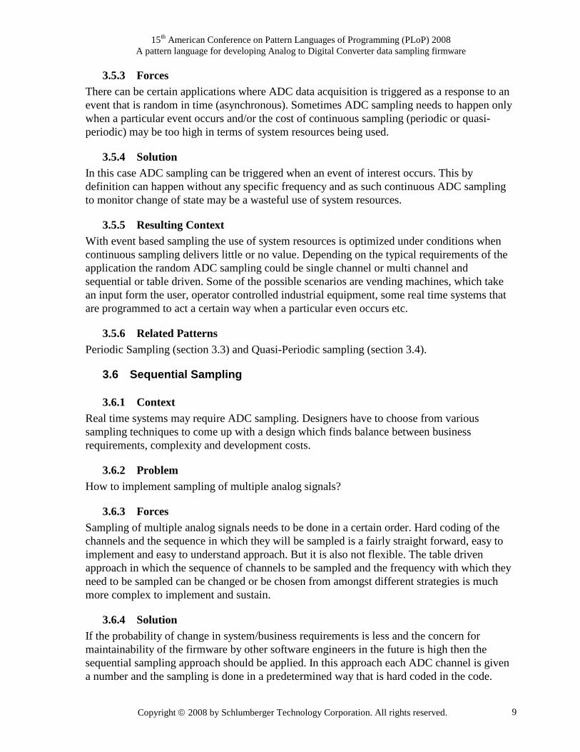
3.5.3 Forces There can be certain applications where ADC data acquisition is triggered as a response to an event that is random in time (asynchronous). Sometimes ADC sampling needs to happen only when a particular event occurs and/or the cost of continuous sampling (periodic or quasi-periodic) may be too high in terms of system resources being used.
3.5.4 Solution In this case ADC sampling can be triggered when an event of interest occurs. This by definition can happen without any specific frequency and as such continuous ADC sampling to monitor change of state may be a wasteful use of system resources.
3.5.5 Resulting Context With event based sampling the use of system resources is optimized under conditions when continuous sampling delivers little or no value. Depending on the typical requirements of the application the random ADC sampling could be single channel or multi channel and sequential or table driven. Some of the possible scenarios are vending machines, which take an input form the user, operator controlled industrial equipment, some real time systems that are programmed to act a certain way when a particular even occurs etc.
3.5.6 Related Patterns Periodic Sampling (section 3.3) and Quasi-Periodic sampling (section 3.4).
3.6 Sequential Sampling
3.6.1 Context Real time systems may require ADC sampling. Designers have to choose from various sampling techniques to come up with a design which finds balance between business requirements, complexity and development costs.
3.6.2 Problem How to implement sampling of multiple analog signals?
3.6.3 Forces Sampling of multiple analog signals needs to be done in a certain order. Hard coding of the channels and the sequence in which they will be sampled is a fairly straight forward, easy to implement and easy to understand approach. But it is also not flexible. The table driven approach in which the sequence of channels to be sampled and the frequency with which they need to be sampled can be changed or be chosen from amongst different strategies is much more complex to implement and sustain.
3.6.4 Solution If the probability of change in system/business requirements is less and the concern for maintainability of the firmware by other software engineers in the future is high then the sequential sampling approach should be applied. In this approach each ADC channel is given a number and the sampling is done in a predetermined way that is hard coded in the code.

15th American Conference on Pattern Languages of Programming (PLoP) 2008 A pattern language for developing Analog to Digital Converter data sampling firmware
Copyright 2008 by Schlumberger Technology Corporation. All rights reserved. 10
More details related to implementation of this approach can be found in the Discrete Periodic Sequential Sampling pattern in section 4.1.
3.6.5 Resulting Context This solution causes the complexity of the code to reduce and hence it is easy to understand and maintain by other engineers who would work in the project in future.
3.6.6 Related Patterns Table driven sampling section 3.7 and Discrete Periodic Sequential Sampling pattern in section 4.1
3.7 Table Driven Sampling
3.7.1 Context Real time systems may require ADC sampling. Designers have to choose from various sampling techniques to come up with a design which finds balance between business requirements, complexity and development costs.
3.7.2 Problem How to implement sampling of multiple analog signals?
3.7.3 Forces Sampling of multiple analog signals needs to be done in a certain order. Hard coding of the channels and the sequence in which they will be sampled is a fairly straight forward, easy to implement and easy to understand approach. But it is also not flexible. The table driven approach in which the sequence of channels to be sampled and the frequency with which they need to be sampled can be changed or be chosen from amongst different strategies is much more complex to implement and sustain. But it is more flexible.
3.7.4 Solution If the probability of change in system/business requirements is considerable and the concern for maintainability of the firmware by other software engineers in the future is not appreciable then the table driven sampling approach should be applied. In this approach for each ADC channel there is a specific entry in a table specifying its order in a sequence, the number of times it needs to be sampled before switching to the next channel in the sequence and other such possible sequences. More details related to implementation of this approach can be found in the Discrete Periodic Table Driven Sampling pattern in section 4.2 and Discrete Quasi-Periodic Table Driven Sampling pattern in section 4.3
3.7.5 Resulting Context This solution causes the complexity of the code to increase but makes the design more flexible and open to future changes in the business requirements.
15th American Conference on Pattern Languages of Programming (PLoP) 2008 A pattern language for developing Analog to Digital Converter data sampling firmware
Copyright 2008 by Schlumberger Technology Corporation. All rights reserved. 11
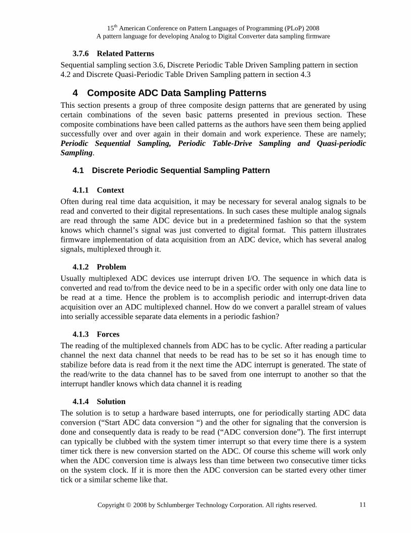
3.7.6 Related Patterns Sequential sampling section 3.6, Discrete Periodic Table Driven Sampling pattern in section 4.2 and Discrete Quasi-Periodic Table Driven Sampling pattern in section 4.3
4 Composite ADC Data Sampling Patterns This section presents a group of three composite design patterns that are generated by using certain combinations of the seven basic patterns presented in previous section. These composite combinations have been called patterns as the authors have seen them being applied successfully over and over again in their domain and work experience. These are namely; Periodic Sequential Sampling, Periodic Table-Drive Sampling and Quasi-periodic Sampling.
4.1 Discrete Periodic Sequential Sampling Pattern
4.1.1 Context Often during real time data acquisition, it may be necessary for several analog signals to be read and converted to their digital representations. In such cases these multiple analog signals are read through the same ADC device but in a predetermined fashion so that the system knows which channel’s signal was just converted to digital format. This pattern illustrates firmware implementation of data acquisition from an ADC device, which has several analog signals, multiplexed through it.
4.1.2 Problem Usually multiplexed ADC devices use interrupt driven I/O. The sequence in which data is converted and read to/from the device need to be in a specific order with only one data line to be read at a time. Hence the problem is to accomplish periodic and interrupt-driven data acquisition over an ADC multiplexed channel. How do we convert a parallel stream of values into serially accessible separate data elements in a periodic fashion?
4.1.3 Forces The reading of the multiplexed channels from ADC has to be cyclic. After reading a particular channel the next data channel that needs to be read has to be set so it has enough time to stabilize before data is read from it the next time the ADC interrupt is generated. The state of the read/write to the data channel has to be saved from one interrupt to another so that the interrupt handler knows which data channel it is reading
4.1.4 Solution The solution is to setup a hardware based interrupts, one for periodically starting ADC data conversion (“Start ADC data conversion “) and the other for signaling that the conversion is done and consequently data is ready to be read (“ADC conversion done”). The first interrupt can typically be clubbed with the system timer interrupt so that every time there is a system timer tick there is new conversion started on the ADC. Of course this scheme will work only when the ADC conversion time is always less than time between two consecutive timer ticks on the system clock. If it is more then the ADC conversion can be started every other timer tick or a similar scheme like that.

15th American Conference on Pattern Languages of Programming (PLoP) 2008 A pattern language for developing Analog to Digital Converter data sampling firmware
Copyright 2008 by Schlumberger Technology Corporation. All rights reserved. 12
Next, we use a switch statement in the interrupt service routine of the “ADC conversion done” interrupt. Some local static variables are used to preserve the state of the sequence in which the data channels have to be read. Figure 2 presents a flow chart of the multiplexed (MUX) ADC driver. The index variable in the flowchart is used for keeping track of the data channel to be read when the interrupt occurs. To ensure that it points to the next data channel that will be read at the next interrupt, it is incremented by one before exiting the interrupt service routine. When the index value reaches the total number of channels (n), a cycle of conversion is completed and it is reset to zero. This allows the first channel to be read during the start of a new cycle. In addition to tracking the next channel to sample, setting the next ADC channel that needs to be read in the ISR gives the next channel some time to stabilize before it ready for conversion.
Figure 2: Discreet periodic sequential sampling pattern
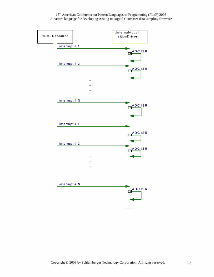
Figure 3 presents a sequence UML diagrams to explain the functioning of the pattern in more detail. It shows the sequence in which the interrupts happen and how they get handled. The interrupts are generated by the ADC resource when it s ready with the data to be read from it. This interrupt is handled by the handler, which implements the Discreet periodic sequential sampling pattern. The sequence diagram shows two cycles in the interrupt sequence, which leads to data being read by the driver twice from the N channels that are multiplexed through the ADC.
Switch(index)ReadADC(index)
SetNextADCbreak;
index = 0;break;
++index >= n index = 0
static int index = 0
Yes
Yes
No (default)
No
ADC interrupt handler routine
Switch(index)ReadADC(index)
SetNextADCbreak;
index = 0;break;
++index >= n index = 0
static int index = 0
Yes
Yes
No (default)
No
ADC interrupt handler routine
15th American Conference on Pattern Languages of Programming (PLoP) 2008 A pattern language for developing Analog to Digital Converter data sampling firmware
Copyright 2008 by Schlumberger Technology Corporation. All rights reserved. 13
Figure 3: ADC acquisition interrupt handler design pattern
:In te rna lA cqu is itionD rive r
A D C IS R
A D C IS R
A D C IS R
A D C IS R
A D C IS R
A D C IS R
:A D C R esource
in te rrup t # 1
in te rrup t # 2
in te rrup t # N
in te rrup t # 1
in te rrup t # 2
in te rrup t # N
………
………
:In te rna lA cqu is itionD rive r
A D C IS R
A D C IS R
A D C IS R
A D C IS R
A D C IS R
A D C IS R
:A D C R esource
in te rrup t # 1
in te rrup t # 2
in te rrup t # N
in te rrup t # 1
in te rrup t # 2
in te rrup t # N
………
………
15th American Conference on Pattern Languages of Programming (PLoP) 2008 A pattern language for developing Analog to Digital Converter data sampling firmware
Copyright 2008 by Schlumberger Technology Corporation. All rights reserved. 14
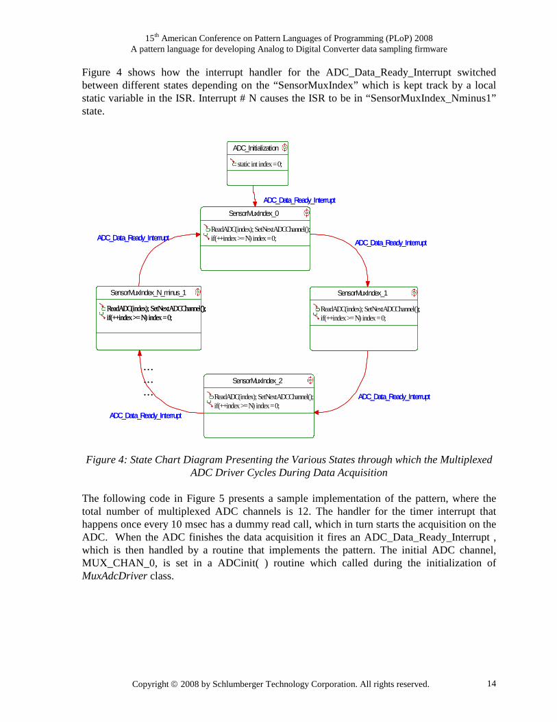
Figure 4 shows how the interrupt handler for the ADC_Data_Ready_Interrupt switched between different states depending on the “SensorMuxIndex” which is kept track by a local static variable in the ISR. Interrupt # N causes the ISR to be in “SensorMuxIndex_Nminus1” state. Figure 4: State Chart Diagram Presenting the Various States through which the Multiplexed
ADC Driver Cycles During Data Acquisition
The following code in Figure 5 presents a sample implementation of the pattern, where the total number of multiplexed ADC channels is 12. The handler for the timer interrupt that happens once every 10 msec has a dummy read call, which in turn starts the acquisition on the ADC. When the ADC finishes the data acquisition it fires an ADC_Data_Ready_Interrupt , which is then handled by a routine that implements the pattern. The initial ADC channel, MUX_CHAN_0, is set in a ADCinit( ) routine which called during the initialization of MuxAdcDriver class.
ADC_Initialization
static int index = 0;
SensorMuxIndex_0
ReadADC(index);SetNextADCChannel();if(++index >= N) index = 0;
ADC_Data_Ready_Interrupt
SensorMuxIndex_1
ReadADC(index);SetNextADCChannel();if(++index >= N) index = 0;
ADC_Data_Ready_Interrupt
SensorMuxIndex_2
ReadADC(index);SetNextADCChannel();if(++index >= N) index = 0;
ADC_Data_Ready_Interrupt
SensorMuxIndex_N_minus_1
ReadADC(index);SetNextADCChannel();if(++index >= N) index = 0;ReadADC(index);SetNextADCChannel();if(++index >= N) index = 0;
ADC_Data_Ready_Interrupt
ADC_Data_Ready_Interrupt
………

15th American Conference on Pattern Languages of Programming (PLoP) 2008 A pattern language for developing Analog to Digital Converter data sampling firmware
Copyright 2008 by Schlumberger Technology Corporation. All rights reserved. 15
Figure 5: Sample code showing implementation of the ‘MUX ADC Driver’ pattern
implemented in the ADC_Data_Ready_Interrupt service routine
4.1.5 Resulting Context Data is read form the mux-ed channel in the desired sequence every time the concerned interrupt is handled. The switch statement and the local static index guarantees that the right
//This happens outside interrupt handler during dev ice //initialization static int SensorMuxIndex = 0; //Interrupt handler implementing ‘MUX ADC driver’ p attern void MuxAdcDriver::MuxAdcInterruptHandler(void) {
… … … … … … … …
if(irq_source & ADC_INT_AVAIL) //ADC data avail able { switch(SensorMuxIndex) { case 0: //MUX_CHAN_0 if(actel_stat & ADC_BUSY_PIN) PreviousCHAN0 = Reg_ADC_DATA; //Set next MUX channel after clearing previous Reg_PORTF0 = ((Reg_PORTF0 & MUX_ADR_CLR) | MUX_CHAN _1); break; case 1: // MUX_CHAN_1 if(actel_stat & ADC_BUSY_PIN) PreviousCHAN1 = Reg_ADC_DATA; //Set next MUX channel after clearing previous Reg_PORTF0 = ((Reg_PORTF0 & MUX_ADR_CLR) | MUX_CHAN _2); break;
… … … … … … … … … … … … … … … …
case 11: // MUX_CHAN_11 if(actel_stat & ADC_BUSY_PIN) PreviousCHAN11 = Reg_ADC_DATA; //Set next MUX channel after clearing previous Reg_PORTF0 = ((Reg_PORTF0 & MUX_ADR_CLR) | MUX_CHAN _0); break; default: SensorMuxIndex = 0; break; } if (++SensorMuxIndex >= 12) SensorMuxIndex = 0; } }

15th American Conference on Pattern Languages of Programming (PLoP) 2008 A pattern language for developing Analog to Digital Converter data sampling firmware
Copyright 2008 by Schlumberger Technology Corporation. All rights reserved. 16
ADC channel is read in the right sequence every time. This of course is going to be true if and only if the hardware keeps functioning without a problem. Another consideration to keep in mind is the jitter that can be caused by different processor implementations. Most microprocessors will vector to an interrupt after the current instruction has completed. If that instruction is an extended instruction then more CPU cycles will be needed before the instruction is completed as compared to a normal instruction. This then causes jitter in that the timing between the interrupt events and leads to varying of the interrupt processing from one execution to another.
4.1.6 Related Patterns There should be only one ADC driver per ADC device and this can be ensured by using the Singleton pattern [GHJV94]. Also the application level code does not need to know about the low level details along with the instantaneous data being collected by the ADC driver. Usually it uses some averaged or filtered value and this functionality can be encapsulated in an Adapter class [GHJV94], which provides an easy to use interface for accessing data from the ADC device.
4.1.7 Known Uses MUX ADC Driver pattern has been widely used in Schlumberger’s real time data acquisition firmware, which involved dealing with ADCs [SLB].
4.2 Discrete Periodic Table Driven Sampling Pattern Periodic sampling with constant periodicity is one case of the periodic sampling described in the Introduction section of this paper. As the title suggests, the timing of this type periodic sampling is constant. Once enabled, new data samples are produced every ∆T seconds. Periodic sampling describes A/D conversions that are synchronized to a timing event.
4.2.1 Context Periodic sampling with constant periodicity is used in applications that require time synchronized data that are searching for a particular event, or where measurements are used to control a device.
4.2.2 Problem There are situations where the signals to be acquired must be acquired according to a fixed timing interval. It may also be required that the signals be acquired in a particular known order especially where frequency or position measurements are concerned. In such cases a simple sequential approach as described in section 3.1 will not be enough. What do we do in such cases ?
4.2.3 Forces The system must conform to a specified timing spec for the acquisition of the signals and their order. Further constraints for this type of acquisition maybe:
• The channels are typically multiplexed.
15th American Conference on Pattern Languages of Programming (PLoP) 2008 A pattern language for developing Analog to Digital Converter data sampling firmware
Copyright 2008 by Schlumberger Technology Corporation. All rights reserved. 17
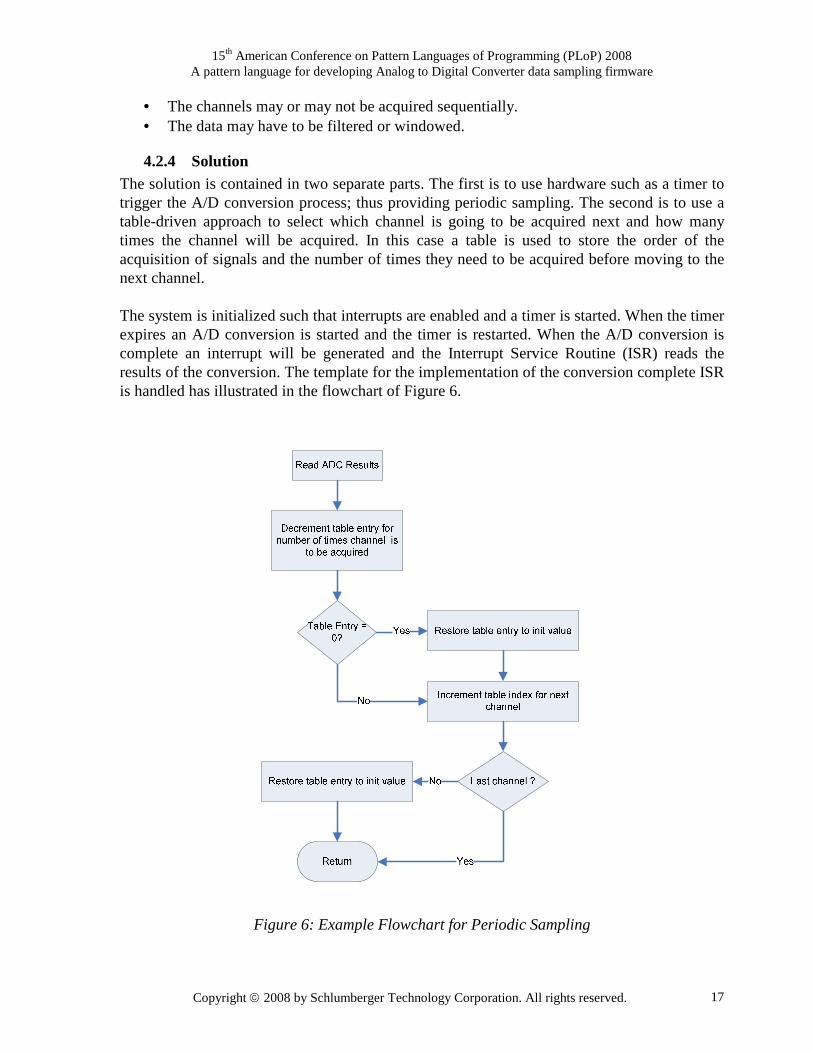
• The channels may or may not be acquired sequentially. • The data may have to be filtered or windowed.
4.2.4 Solution The solution is contained in two separate parts. The first is to use hardware such as a timer to trigger the A/D conversion process; thus providing periodic sampling. The second is to use a table-driven approach to select which channel is going to be acquired next and how many times the channel will be acquired. In this case a table is used to store the order of the acquisition of signals and the number of times they need to be acquired before moving to the next channel. The system is initialized such that interrupts are enabled and a timer is started. When the timer expires an A/D conversion is started and the timer is restarted. When the A/D conversion is complete an interrupt will be generated and the Interrupt Service Routine (ISR) reads the results of the conversion. The template for the implementation of the conversion complete ISR is handled has illustrated in the flowchart of Figure 6.
Figure 6: Example Flowchart for Periodic Sampling
15th American Conference on Pattern Languages of Programming (PLoP) 2008 A pattern language for developing Analog to Digital Converter data sampling firmware
Copyright 2008 by Schlumberger Technology Corporation. All rights reserved. 18
4.2.5 Resulting Context Multiplexed A/D conversion is achieved with the constraint of a precise sampling time. In complex cases where a channel needs to be sampled several times before switching to another channel and the next logical channel is not the next physical channel then a table implementation is an efficient approach. The table approach provides a means to extend the number of acquisitions required for a particular channel before advancing to the next channel, typically used for over sampling acquired data. In this way a particular channel acquisition order can be defined and a periodic cycle time is achieved. As discussed in section 3.1.5, another consideration to keep in mind is the jitter that can be caused by different processor implementations. Most microprocessors will vector to an interrupt after the current instruction has completed. If that instruction is an extended instruction then more CPU cycles will be needed before the instruction is completed as compared to a normal instruction. This then causes jitter in that the timing between the interrupt event and actually processing the interrupt varies from one execution to another.
4.2.6 Related Patterns There should be only one ADC driver per ADC device and this can be ensured by using the Singleton pattern [GHJV94]. Also the application level code does not need to know about the low level details along with the instantaneous data being collected by the ADC driver. Usually it uses some averaged or filtered value and this functionality can be encapsulated in an Adapter class [GHJV94], which provides an easy to use interface for accessing data from the ADC device.
4.2.7 Known Uses Multiplexed A/D conversion with constant periodicity has been employed on projects in Schlumberger [SLB].
4.3 Quasi-Periodic Table Driven Sampling Pattern
4.3.1 Context The most common approach for performing A/D conversion is to employ a hardware trigger, usually resulting in periodic sampling. Using a hardware trigger is especially desirable when there a system has timing constraints, which requires sampling be done at specific time intervals. When the A/D conversion process is completed, the output of the ADC is read and the ADC is configured for the next conversion process. For multi-channel conversion, the general sampling method employed is the sequentially driven. This pattern describes an alternative to the periodic sampling that provides the flexibility that is lacking in periodic sampling.
4.3.2 Problem When the ADC is used for sequential multiplexing data acquisition, it is generally desirable to sample each channel at the same rate. This requires that the start of the conversion process is pre-determined and triggered by hardware say for example by a timer. In the event that such

15th American Conference on Pattern Languages of Programming (PLoP) 2008 A pattern language for developing Analog to Digital Converter data sampling firmware
Copyright 2008 by Schlumberger Technology Corporation. All rights reserved. 19
hardware resource is unavailable, and the ADC data acquisition does not need to be sampled at specific timing interval, then an alternative means of performing the A/D conversion process is required.
4.3.3 Forces Other tasks in a system may generate interrupts that may result in significant variation in time interval between consecutive samplings.
4.3.4 Solution The solution presented here uses software to trigger the A/D conversion process. In this case, the ADC will, at initialization be configured for soft-trigger. After the ADC is initialized and setup, the start of conversion (SOC) can be initiated when required, usually as a function call. The code template in Figure 7 illustrates the SOC in an infinite loop, in which ADC starts a conversion every time control returns to the start of the infinite for loop. If the loop is never exited, then the sampling is categorized as periodic sampling with the exception that the conversion process is software triggered. In general however, the loop will be exited as a result of some random event (such as an interrupt), thus, the periodicity of the A/D process is classified as quasi-periodic sampling.
void main(void)
{
adcInitialization();
.
.
.
for(; ; )
{
startAdcConversion();
.
.
.
}
}
Figure 7: Code template for Software ADC Start of Conversion Trigger
When the ADC has completed the conversion, the system needs to be notified so that the output of the ADC can be read and the ADC configured for the next conversion process. The ADC’s end of conversion (EOC) can be determined either by software polling or could be interrupt-driven. Software polling incurs the overhead of wasting processor time; tying down the processor thus, preventing it from performing other tasks [Minasi93, Rusling97]. Therefore, to avoid the penalty of software polling, and to meet our application requirements, we have employed the use of an interrupt to signify the end of an A/D conversion process. When EOC interrupt is generated, the output of the ADC is read in the interrupt service
15th American Conference on Pattern Languages of Programming (PLoP) 2008 A pattern language for developing Analog to Digital Converter data sampling firmware
Copyright 2008 by Schlumberger Technology Corporation. All rights reserved. 20
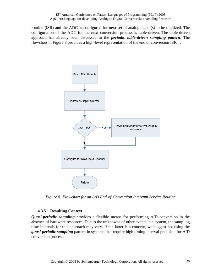
routine (ISR) and the ADC is configured for next set of analog signal(s) to be digitized. The configuration of the ADC for the next conversion process is table-driven. The table-driven approach has already been discussed in the periodic table-driven sampling pattern. The flowchart in Figure 8 provides a high-level representation of the end of conversion ISR. .
Figure 8: Flowchart for an A/D End-of-Conversion Interrupt Service Routine
4.3.5 Resulting Context Quasi-periodic sampling provides a flexible means for performing A/D conversion in the absence of hardware resources. Due to the unknowns of other events in a system, the sampling time intervals for this approach may vary. If the latter is a concern, we suggest not using the quasi-periodic sampling pattern in systems that require high timing interval precision for A/D conversion process.
15th American Conference on Pattern Languages of Programming (PLoP) 2008 A pattern language for developing Analog to Digital Converter data sampling firmware
Copyright 2008 by Schlumberger Technology Corporation. All rights reserved. 21
4.3.6 Related Patterns The previous two patterns are similar to this as they all lend themselves equally well to either sequential or table driven approach but differ in the fact that they use a hardware based trigger. There should be only one ADC driver per ADC device and this can be ensured by using the Singleton pattern [GHJV94]. Also the application level code does not need to know about the low level details along with the instantaneous data being collected by the ADC driver. Usually it uses some averaged or filtered value and this functionality can be encapsulated in an Adapter class [GHJV94], which provides an easy to use interface for accessing data from the ADC device.
4.3.7 Known Uses Multiplexed A/D conversions using the quasi-periodic sampling pattern have been employed on projects in Schlumberger [SLB].
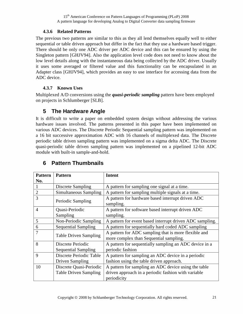
5 The Hardware Angle It is difficult to write a paper on embedded system design without addressing the various hardware issues involved. The patterns presented in this paper have been implemented on various ADC devices. The Discrete Periodic Sequential sampling pattern was implemented on a 16 bit successive approximation ADC with 16 channels of multiplexed data. The Discrete periodic table driven sampling pattern was implemented on a sigma delta ADC. The Discrete quasi-periodic table driven sampling pattern was implemented on a pipelined 12-bit ADC module with built-in sample-and-hold.
6 Pattern Thumbnails
Pattern No.
Pattern
Intent
1 Discrete Sampling A pattern for sampling one signal at a time. 2 Simultaneous Sampling A pattern for sampling multiple signals at a time. 3
Periodic Sampling A pattern for hardware based interrupt driven ADC sampling.
4 Quasi-Periodic Sampling
A pattern for software based interrupt driven ADC sampling.
5 Non-Periodic Sampling A pattern for event based interrupt driven ADC sampling. 6 Sequential Sampling A pattern for sequentially hard coded ADC sampling 7
Table Driven Sampling A pattern for ADC sampling that is more flexible and more complex than Sequential sampling.
8 Discrete Periodic Sequential Sampling
A pattern for sequentially sampling an ADC device in a periodic fashion
9 Discrete Periodic Table Driven Sampling
A pattern for sampling an ADC device in a periodic fashion using the table driven approach.
10 Discrete Quasi-Periodic Table Driven Sampling
A pattern for sampling an ADC device using the table driven approach in a periodic fashion with variable periodicity

15th American Conference on Pattern Languages of Programming (PLoP) 2008 A pattern language for developing Analog to Digital Converter data sampling firmware
Copyright 2008 by Schlumberger Technology Corporation. All rights reserved. 22
7 Acknowledgments The authors would like to thank Gerard Meszaros for shepherding this paper for PLoP 2007. The authors are grateful to Lise Hvatum for her constant support and encouragement during the process of writing this paper. Thanks also go out to Linda Rising for providing very useful comments during a patterns boot-camp.
8 References
1. [Bammi06] “Patterns for a Designing a Generic Device Driver for Interrupt Driven I/O”, Bammi S., presented at the Pattern Languages of Programming conference, Portland, Oregon, USA. (October 2006).
2. [Bammi07] “A generic real time embedded data acquisition pattern language for interrupt driven I/O”, Bammi S., presented at the European Conference of Pattern Languages of Programming conference, Bavaria, Germany. (July 2007).
3. [Ganssle01] Interrupt Latency, Ganssle, J. G. Embedded Systems Programming, VOL. 14 NO.12, October 2001. Link: http://www.embedded.com/story/OEG20010918S0052 (accessed on 21st November 2006).
4. [GHJV94] Gamma, E., Helm, R., Johnson, R. and Vlissides, J., “Design Patterns: Elements of Reusable Object-Oriented Software”, Addison-Wesley, Boston, 1994.
5. [Kalinsky03] Kalinsky, D., Introduction to Real-Time Operating Systems, Introductory Course for Real-Time Software Development using an RTOS, Courseware Version 2.1, 3-05-03, D. Kalinsky Associates, 2003.
6. [Kalinsky06] Kalinsky, D., Architectural Design of Device Drivers, Tutorial # ESC-505, Embedded Systems Conference 2006 San Jose – Silicon Valley, D. Kalinsky Associates, 2006.
7. [Minasi93] Minasi, M. “Interrupts Made Easy”, Article in COMPUTE!, Issue 149, Page 60, February 1993. Link: http://www.atarimagazines.com/compute/issue149/60_Interrupts_made_easy.php (Accessed on May 22 2007)
8. [Rusling97] Rusling, D., “The Linux Kernel”, DRAFT, Version 0.1-10(30), ‘Polling and Interrupts’ subsection, April 1997. Link: http://www.science.unitn.it/~fiorella/guidelinux/tlk/tlk-html.html (Accessed on May 22 2007)
9. [SLB] Internal Schlumberger technical literature. 10. [Staller05] Staller, L., Understanding analog too digital converter specifications, article
on Embedded.com (February 2005), Link: http://www.embedded.com/showArticle.jhtml?articleID=60403334 (accessed April 15th 2007)
11. [WIKI07] Analog to digital converter Link: http://en.wikipedia.org/wiki/Analog-to-digital_converter (accessed April 15th 2007)