pastime projects manual for · pastime projects . manual for ... the stories that followed were...
TRANSCRIPT
Pastime Projects
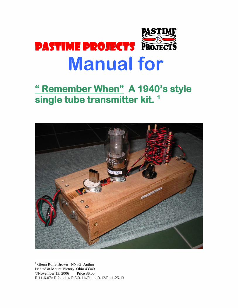
Manual for “ Remember When” A 1940’s style single tube transmitter kit. 1
1 Glenn Rolfe Brown NN8G Author Printed at Mount Victory Ohio 43340 ©November 13, 2006 Price $6.00 R 11-6-07// R 2-1-11// R 5-3-11//R 11-13-12/R 11-25-13
“RemembeR when” A 1940’s style single tube tRAnsmitteR ~ Author’s Notes ~ Rev May 3, 2011 In 1952 I built my first One Tube transmitter. The transmitter was built from a design in The Radio Amateur’s Handbook 26th edition, 19492. 50 years later I built another. I took it to hamfests for “show and tell”. Many hams recognized the radio and would start a conversation: “I remember when …….” The stories that followed were great reminders of homebrew days gone by and the wonderful memories of our early days with amateur radio. With that in mind, we bring back a kit very much like that early Handbook design. If one young person can today share the excitement of building their our own transmitter, if one of these radios is taken to an amateur radio club for show and tell, or if some ambitious radio amateur modifies the kit to comply with today’s FCC specifications and puts it on the air, then the time and effort to produce this kit has paid off! Thanks for your interest and encouragement in supporting this project. To my fellow engineers, technicians, students and elmers I say enjoy this project which, for you, I name ……..
the “RemembeR when” tRAnsmitteR ENJOY! Glenn Brown, NN8G November 2006
May 3, 2011: We have added a front panel (wood slat) to the transmitter. It is the builders option whether to add it or not. While it takes away from the vintage look of the original, it may keep hands and fingers out of the high voltage points under the chassis. It is important to remember that high voltage is present when this transmitter is in use. Understand the dangers of high voltage before supplying power to this kit. High voltage can kill! 2 American Radio Relay League, Inc, 225 Main Street, Newington, CT 06111-1494 www.arrl.org PAGE 2
“RemembeR when” A 1940’s style single tube tRAnsmitteR overview HERE IS A RADIO TRANSMITTER KIT FOR YOU TO BUILD; BE IT JUST FOR THE SATISFACTION OF WORKING WITH WOOD, SOLDERING, WIRING, OR READING SCHEMATICS. OR SHARING WITH YOUR LOCAL CLUB. PERHAPS SOME MIGHT BUILD TO GIVE AS A GIFT TO A FELLOW HAM OR TO AN ‘ELMER’ AS A WAY TO REMEMBER WHEN. WHATEVER REASON YOU CHOOSE TO BUILD THIS KIT, I HOPE YOUR ENJOY THE TRIP BACK TO THE 1940’S. IF YOU ARE PLEASED WITH THIS KIT WILL YOU SHARE WITH OTHERS? ~~~~~~ THE PROJECT IS BASED ON THE ARTICLE “A Simple Single-Tube Transmitter” published in the ARRL3 1948-1949 “The Radio Amateur’s Handbook©. IN THE BACK OF THIS MANUAL YOU WILL FIND A REPRINT OF THE ORIGINAL ARRL ARTICLE, THANKS TO THE PERMISSION OF THE AMERICAN RADIO RELAY LEAGUE. ALSO IN THE BACK OF THIS MANUAL YOU WILL FIND LARGER COPIES OF THE ILLUSTRATIONS THAT MAY BE REMOVED TO USE AS GUIDES DURING THE BUILDING PROCESS. ~~~~~~ PARTS USED IN THE ORIGINAL RADIO IN 1948 MAY NOT BE AVAILABLE IN KIT BUILDING QUANTITY. WE MAY SUBSTITUTE PARTS WHILE KEEPING THE PHYSICAL APPEARANCE OF THE ORIGINAL RADIO AS MUCH AS POSSIBLE. BECAUSE OF PARTS AVAILABILITY, KITS MAY CHANGE IN COMPONENTS AND COST FROM TIME TO TIME. THIS IS INTENDED TO BE A FUN PROJECT. FCC LAW COVERS THE TECHNICAL SPECIFICATIONS FOR TRANSMITTER EMMISSIONS AS WELL AS WHO IS AUTHORIZED TO OPERATE THIS KIND OF EQUIPMENT. FURTHER, A HIGH VOLTAGE POWER SUPPLY IS REQUIRED TO OPERATE THIS TRANSMITTER. THIS KIT AND MANUAL SUPPLIED WITH THIS KIT DO NOT ATTEMPT TO COVER THE TECHNICAL, LEGAL, AND SAFETY ASPECTS OF OPERATION OF THIS TRANSMITTER. WE ENCOURAGE CONTINUED LEARNING OF THESE ASPECTS OF RADIO. 3 American Radio Relay League, Inc, 225 Main Street, Newington, CT 06111-1494 www.arrl.org PAGE 3
Revised 12-07-06 “RemembeR when” A 1940’s style single tube tRAnsmitteR chAssis pRepARAtion [ ] The chassis is constructed of two strips and two end pieces. These are made of oak wood. While the wood parts may be used as supplied, you may want to finish with stain and/or protective coating. It is suggested that any wood preparation be performed prior to the following assembly steps. [ ] Once the boards are prepared refer to figure 1 and figure 2. Study your wood and plan how you will assemble the parts. Early on, identify where the “front” and “back” of the assembly will be. Note that when the front is facing towards you, the octal sockets will be on the left. The drilled hole for the capacitor will be on the right side of the front strip. Note there is a ‘slot’ or ‘notch’ at the top left of the left end piece. This is where the three power wires will exit for connection to a power supply. Locate this notch. Prepare it along with the flat head screw drilling in the next step. [ ] Mounting screws These are the (6) brass #6 X ¾ inch flat head screws and the (2) brass #6 X ¾ inch round (pan) head screws. The location of the two pan head screws is noted in figure 2. Mark hole centers and drill as needed. Typical hole dimensions for all the eight mounting screws are shown in the lower left of figure 2. [HINT: The drilling of the six flat head screws is simplified by using an inexpensive #6 screw pilot tool4] [ ] Tube socket fitting Tube socket diameters vary from one manufacturer to another. You will likely have to cut away a small amount of wood on the slats to allow the wood sockets to mount properly. Study figure 1 and 2 for location. This process should be performed slowly. Remove only enough wood for socket fit. [HINT: The edge of the slats can be enlarged with a flap wheel5 in a drill press.] [ ] Tube socket mounting holes Each tube socket will be held in place with #6-32 X ½ steel round head screws and nuts (4 supplied). Hold each socket in place and mark the centers for the screws. Remove the sockets and drill. Use #25 drill bit or 5/32 drill bit for looser fit. [ ] Variable Capacitor The variable capacitor has a 3/8-32 threaded shoulder. Locate the drill center as dimensioned in Figure 2. Drill with #X drill or 13/32 drill bit for looser fit. 4 Vermont American® #6 wood screw pilot drill #16606. Available at Ace Hardware. .© 5 Forney® 120 GRIT 1”DIA x 1” Flap Wheel # 60192. Available at Ace Hardware. PAGE4

Revised 12-07-06 “RemembeR when” A 1940’s style single tube tRAnsmitteR chAssis pRepARAtion [ ] Coil mounting sticks The original transmitter (“Remember When?”) made use of “penny sucker sticks”. In this day and age the sucker will cost a lot more than a penny, and the “stick” won’t be made of wood. We have found suitable dowels that provide a close match to the original “penny sucker sticks”. Locate the three stick locations from Figure 2. (See the photo for help). We want these sticks to be a fairly tight fit in the holes. Recommended drill size is 9/64 inch. [HINT: If these sticks are too loose in the holes, they can be glued in place later when assembly is finished. If too tight, lightly sand down the diameter of the stick]. Do not leave the sticks in the holes at this time. [ ] Fahnestock clips for key Two Fahnestock clips on the left end piece are used for the key connection to the transmitter. These are held with #6-32 screws and hardware. The dimensions for drilling these holes are shown in the left side view in figure 2. Drill these holes with your #25 or 5/32 drill bit as used on the tube sockets.
THIS CONCLUDES THE CHASSIS PREPARATION. PAGE 5
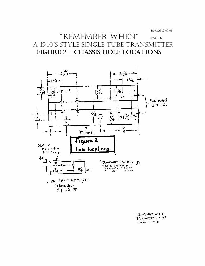
Revised 12-07-06 “RemembeR when” PAGE 6 A 1940’s style single tube tRAnsmitteR FiguRe 2 – chAssis hole locAtions
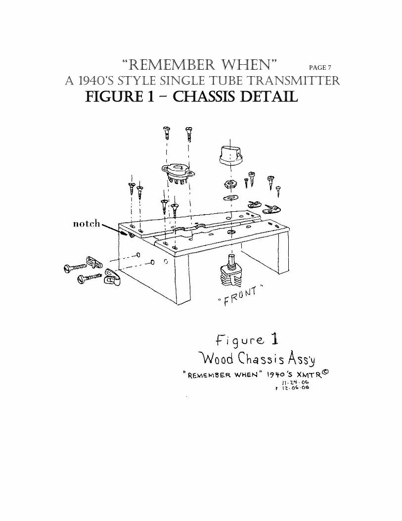
“RemembeR when” PAGE 7
A 1940’s style single tube tRAnsmitteR FiguRe 1 – chAssis detAil
11/30/06 r 12/18/06
“RemembeR when” A 1940’s style single tube tRAnsmitteR chAssis pARts Assembly PLEASE NOTE: The parts will be assembled to the wood chassis in this description of your transmitter. The sockets will have the “key” (notch in the socket) towards the front of the transmitter. Figure 1 and the photo will be most helpful during assembly. The ‘sucker sticks’ that hold the coils will be added as the last step. At this time the wood parts should be prepared for assembly. [ [ Joining the wood parts. If you have not already done so, assemble the slats and end pieces. Work carefully and keep everything square. Install four #6 x ¾ inch flat head screws at the four outside corners of the chassis, followed by two additional flat head screws on the middle left end slats. [ ] Link coil clips Locate the two brass #6 x ¾ inch round (pan) head screws. Mount 1 Fahnestock clip and 1 solder lug on each screw and screw these down on the right side end piece for later assembly of the link coil. [ ] Tube socket mounting Mount the two octal sockets. Use #6-32 x ½ steel round head screws and nuts. ( 4 required) Note the tube sockets mount from the top of the chassis. Orient the keys towards the front of the chassis. On the bottom side of the crystal socket, a two lug terminal strip is mounted on the rear 6-32 bolt. (see Figure 3). [ ] Variable capacitor. Carefully push the variable capacitor up through the bottom of the chassis. Attach it with the washer and nut supplied. Handle gently; be careful not to bend the capacitor components. [ ] Capacitor knob. At this time assemble the knob on the capacitor. Loosen the set screw, then assemble the knob as low as possible without binding. Set the set screw. Position of the knob pointer is not important at this time. [ [ Key connections Locate the #6-32 x 1 inch screws (2 required), two Fahnestock clips, and two solder lugs for the key connections on the left end piece. Mount the clips on the outside, then two solder lugs and two #6-32 nuts on the inside of the chassis. Turn the clips as shown in the illustrations. OTHER THAN PLACING THE COIL ‘SUCKER STICKS’ THIS COMPLETES THE CHASSIS PARTS ASSEMBLY.
PAGE 8 12/03/06© Rev12/7/06 12/16/06 Rev 10/29/07
“RemembeR when” A 1940’s style single tube tRAnsmitteR wiRing instRuctions A WORD ABOUT FIGURE 3: IT IS EASIER THAN IT LOOKS. HERE ARE SOME TIPS: EACH STEP IS SHOWN IN SEQUENCE. FOR INSTANCE, STEP [2] WIRE IS PICTURED UNDER THE STEP [8] WIRE, AND STEP [G] WIRE RUNS OVER TOP OF STEP [8] WIRE. YOU CAN LIGHTLY COLOR EACH WIRE AS YOU FINISH THAT STEP. REFER TO THE SCHEMATICS FOR HELP. IT IS A VERY LOGICAL PICTORIAL IF TAKEN IN STEPS. GOOD LUCK! PLEASE NOTE: <>In the following instructions “prepare a wire” means cut a wire to the length
given, then strip back between 1/4 and 3/8 inch of insulation from each end. Tin the exposed wire ends if needed.
<>Prepare the wires from the small roll of hook-up wire provided. <>The long red, black, and green wires are provided in the kit. <>The instructions include check-off blocks ( ) for you to pencil in as you complete
the work. Terms such as (NS), (S2), and (S3) are terms describing when (and when not) to solder. For instance (NS) means connect the wire in place, but do not solder. S3 would mean to solder three wires to the connecting point.
<>Make sure the wires do not short to other pins or wires. If necessary, take a little insulating sleeve or spare wire insulation and cover the wire leads. <> Soldering of these parts requires skill. Read and practice or get help with soldering if this is new to you. ~~~~~~~~~~~~~~~~~~~~~~~~~ Refer to Figure 3 for the following work. You have an extra copy of Figure 3 in the back of your booklet. Remove it to follow these instructions. Each step has a number such as [1], [2], [3] and so on. In Figure 3 you will find the same step numbering system. It may help to color each wire as you finished the step. Do not confuse socket pin numbers 1,2,3,etc. with Step numbers [1],[2], [3] and so on. ( ) [1] Prepare the lead lengths of a 0.01 capacitor to fit between Pin 1 (NS) and Pin 4 (NS) of the tube socket. Keep the leads short, but free of other pins. Use insulation on the wires if necessary. ( ) [2] Prepare the 20 inch red wire and connect one end to Pin 4 of the tube socket.(NS) Dress the other end along the left side piece towards the notch. (see Fig 1 and Fig 2)
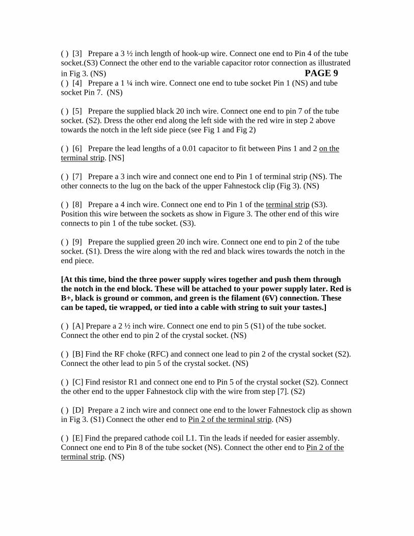
( ) [3] Prepare a 3 ½ inch length of hook-up wire. Connect one end to Pin 4 of the tube socket.(S3) Connect the other end to the variable capacitor rotor connection as illustrated in Fig 3. (NS) PAGE 9 ( ) [4] Prepare a 1 ¼ inch wire. Connect one end to tube socket Pin 1 (NS) and tube socket Pin 7. (NS) ( ) [5] Prepare the supplied black 20 inch wire. Connect one end to pin 7 of the tube socket. (S2). Dress the other end along the left side with the red wire in step 2 above towards the notch in the left side piece (see Fig 1 and Fig 2) ( ) [6] Prepare the lead lengths of a 0.01 capacitor to fit between Pins 1 and 2 on the terminal strip. [NS] ( ) [7] Prepare a 3 inch wire and connect one end to Pin 1 of terminal strip (NS). The other connects to the lug on the back of the upper Fahnestock clip (Fig 3). (NS) ( ) [8] Prepare a 4 inch wire. Connect one end to Pin 1 of the terminal strip (S3). Position this wire between the sockets as show in Figure 3. The other end of this wire connects to pin 1 of the tube socket. (S3). ( ) [9] Prepare the supplied green 20 inch wire. Connect one end to pin 2 of the tube socket. (S1). Dress the wire along with the red and black wires towards the notch in the end piece. [At this time, bind the three power supply wires together and push them through the notch in the end block. These will be attached to your power supply later. Red is B+, black is ground or common, and green is the filament (6V) connection. These can be taped, tie wrapped, or tied into a cable with string to suit your tastes.] ( ) [A] Prepare a 2 ½ inch wire. Connect one end to pin 5 (S1) of the tube socket. Connect the other end to pin 2 of the crystal socket. (NS) ( ) [B] Find the RF choke (RFC) and connect one lead to pin 2 of the crystal socket (S2). Connect the other lead to pin 5 of the crystal socket. (NS) ( ) [C] Find resistor R1 and connect one end to Pin 5 of the crystal socket (S2). Connect the other end to the upper Fahnestock clip with the wire from step [7]. (S2) ( ) [D] Prepare a 2 inch wire and connect one end to the lower Fahnestock clip as shown in Fig 3. (S1) Connect the other end to Pin 2 of the terminal strip. (NS) ( ) [E] Find the prepared cathode coil L1. Tin the leads if needed for easier assembly. Connect one end to Pin 8 of the tube socket (NS). Connect the other end to Pin 2 of the terminal strip. (NS)
( ) [F] Find the 470 pf capacitor C1... Do not cut the leads. Find some scrap wire insulation and put it on each wire lead. Connect the capacitor to tube Pin 8 (NS) and Pin 2 of the terminal strip (S4). PAGE 10 12/03/06© Rev12/7/06 12/16/06
“RemembeR when” A 1940’s style single tube tRAnsmitteR wiRing instRuctions ( ) [G] Prepare a 2 ¾ inch wire and connect it to Pin 8 (S3) of the tube socket. Run the other end over to Pin 8 (S1) of the crystal socket. ( ) [H] Prepare a 2 ¾ inch wire and connect it to Pin 3 (S1) of the tube socket. Run the other end to the post on the variable capacitor C4 as shown in Figure 3. (S1) COIL L2 WILL LATER CONNECT TO THE VARIABLE CAPACITOR AS SHOWN AND SOLDERED IN PLACE. THE LINK COIL CONNECTS TO THE FALNESTOCK CLIPS TO COMPLETE THE WIRING. CHECK YOUR CONNECTIONS AT THIS TIME. PAGE 11
r 12/13/06 “RemembeR when” PAGE 12 A 1940’s style single tube tRAnsmitteR FiguRe 3 – chAssis wiRing pictoRiAl
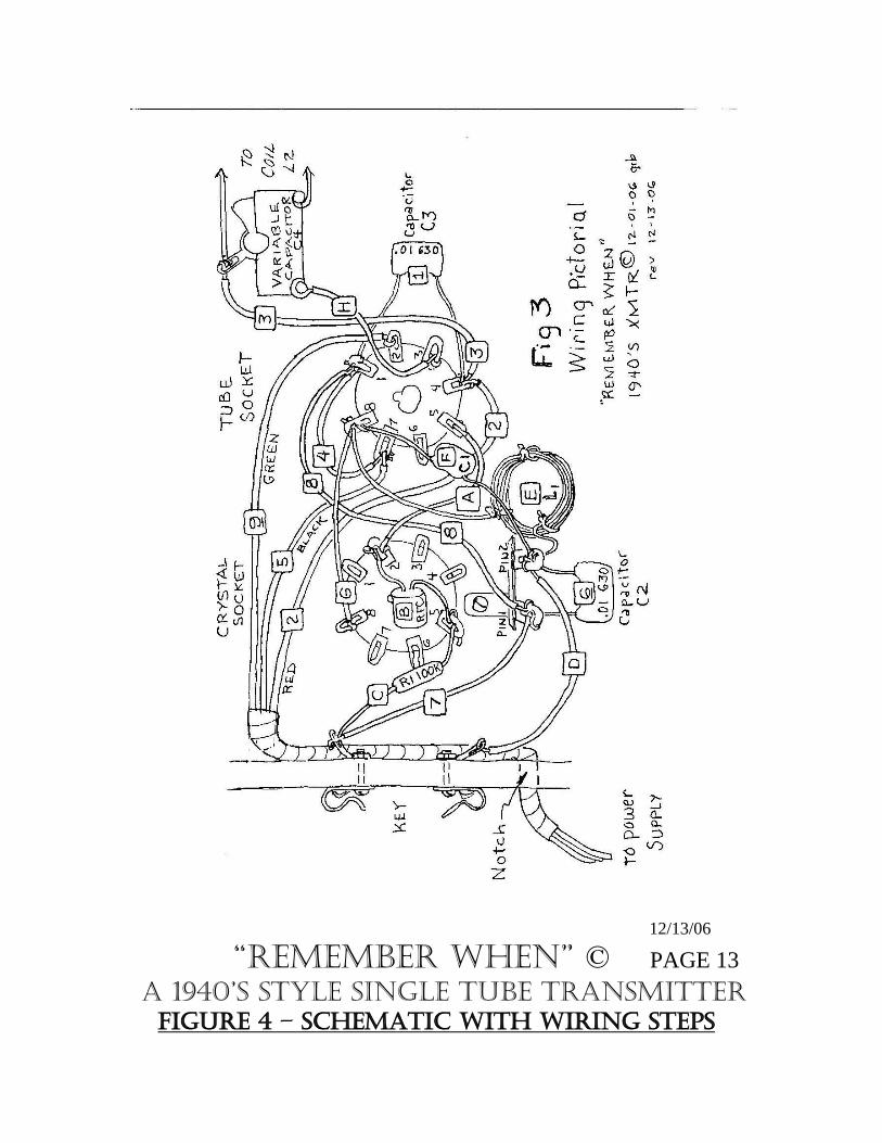
12/13/06 “RemembeR when” © PAGE 13 A 1940’s style single tube tRAnsmitteR FiguRe 4 – schemAtic with wiRing steps
“RemembeR when” © 12/13/06
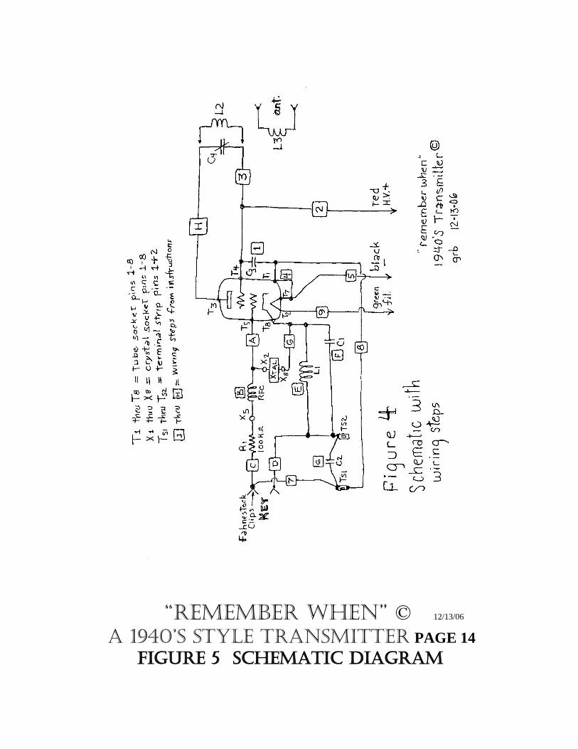
A 1940’s style tRAnsmitteR PAGE 14 FiguRe 5 schemAtic diAgRAm
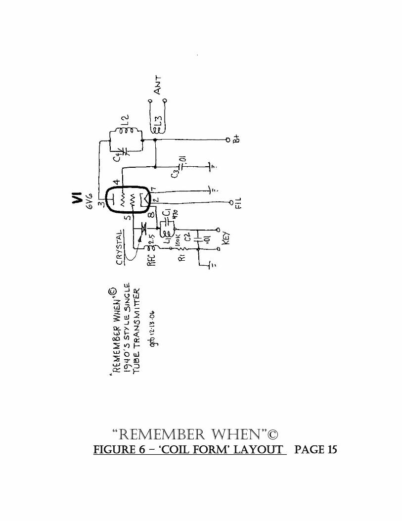
“RemembeR when”© FiguRe 6 – ‘coil FoRm’ lAyout pAge 15
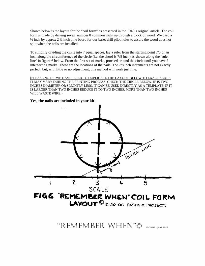
Shown below is the layout for the “coil form” as presented in the 1940’s original article. The coil form is made by driving seven number 8 common nails up through a block of wood. We used a ½ inch by approx 2 ½ inch pine board for our base; drill pilot holes to assure the wood does not split when the nails are installed. To simplify dividing the circle into 7 equal spaces, lay a ruler from the starting point 7/8 of an inch along the circumference of the circle (i.e. the chord is 7/8 inch) as shown along the ‘ruler line’ in figure 6 below. From the first set of marks, proceed around the circle until you have 7 intersecting marks. These are the locations of the nails. The 7/8 inch increments are not exactly perfect, but, with little or no adjustment, this method will work just fine. [PLEASE NOTE: WE HAVE TRIED TO DUPLICATE THE LAYOUT BELOW TO EXACT SCALE. IT MAY VARY DURING THE PRINTING PROCESS. CHECK THE CIRCLE BELOW. IF IS TWO INCHES DIAMETER OR SLIGHTLY LESS, IT CAN BE USED DIRECTLY AS A TEMPLATE. IF IT IS LARGER THAN TWO INCHES REDUCE IT TO TWO INCHES. MORE THAN TWO INCHES WILL WASTE WIRE.} Yes, the nails are included in your kit!
“RemembeR when”© 12/25/06 r jun7 2012
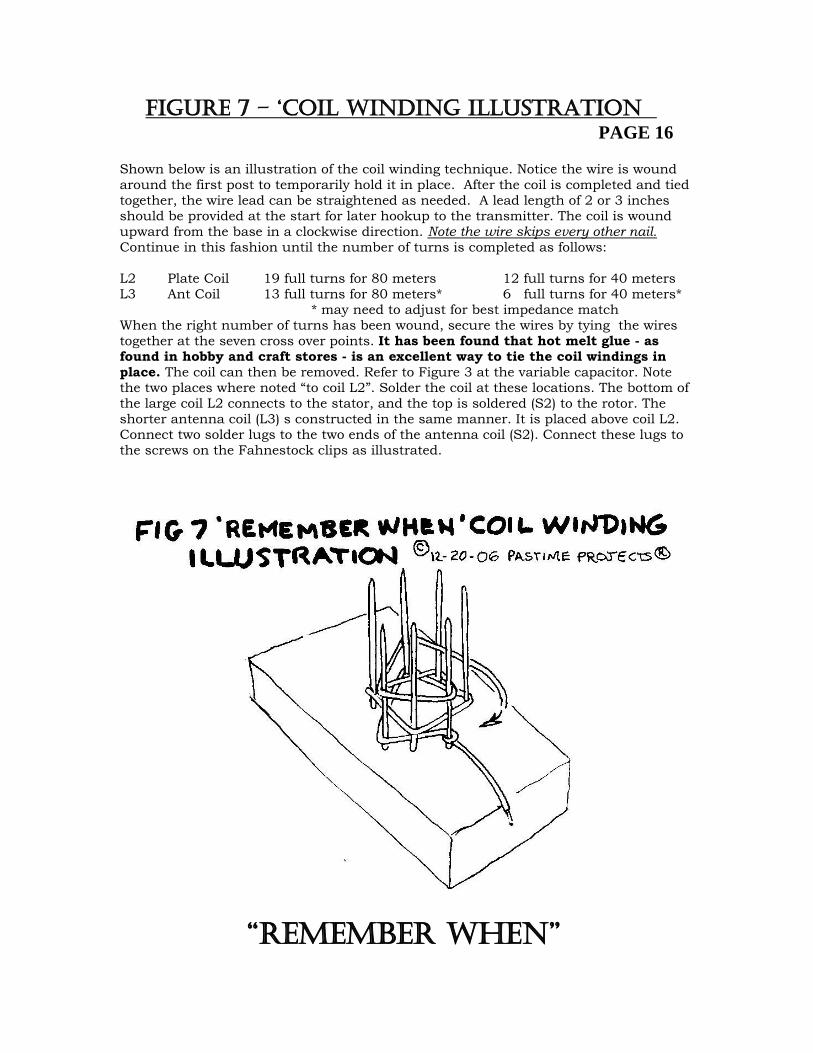
FiguRe 7 – ‘coil winding illustRAtion PAGE 16 Shown below is an illustration of the coil winding technique. Notice the wire is wound around the first post to temporarily hold it in place. After the coil is completed and tied together, the wire lead can be straightened as needed. A lead length of 2 or 3 inches should be provided at the start for later hookup to the transmitter. The coil is wound upward from the base in a clockwise direction. Note the wire skips every other nail. Continue in this fashion until the number of turns is completed as follows: L2 Plate Coil 19 full turns for 80 meters 12 full turns for 40 meters L3 Ant Coil 13 full turns for 80 meters* 6 full turns for 40 meters* * may need to adjust for best impedance match When the right number of turns has been wound, secure the wires by tying the wires together at the seven cross over points. It has been found that hot melt glue - as found in hobby and craft stores - is an excellent way to tie the coil windings in place. The coil can then be removed. Refer to Figure 3 at the variable capacitor. Note the two places where noted “to coil L2”. Solder the coil at these locations. The bottom of the large coil L2 connects to the stator, and the top is soldered (S2) to the rotor. The shorter antenna coil (L3) s constructed in the same manner. It is placed above coil L2. Connect two solder lugs to the two ends of the antenna coil (S2). Connect these lugs to the screws on the Fahnestock clips as illustrated.
“RemembeR when”
A 1940’s style single tube tRAnsmitteR Crystal Selection Rev Jan 5, 2013 BACKGROUND The original design6 used 80 meter crystals for both 80 and 40 meter operation. For various reasons, today’s amateurs want to use 40 meter crystals on 40 meters. To allow use of 40 meter crystals, we have made a few suggestions on this page in the past. In earlier versions of this manual, we suggested inserting a second 500pf mica capacitor in series with the original one in the cathode LC circuit. (The spare capacitor is included in each kit). You can try that. This doesn’t always work well, probably due to crystal variation. A BETTER FIX We have found that reducing the cathode coil from the original 5 turns to 2 1/3 turns provides improved output, more stability and reduced chirp. Leave the original 500 pf mica capacitor in the circuit as shown in Fig 3 of this manual. Make this change and solder in place. Once you are done and ready to test, experiment with antenna loading and tuning capacitor setting should result in a “sweet spot” where CW operation will be acceptable. 80 METER CONVERSION To return your transmitter oscillator to 80 meter use, you will have to replace the cathode coil with another wound with the original 5 turns. The coils are wound with a 1 ¼ inch inside diameter and use number 18 size wire or similar. Solid wire is easier to work with. Use a piece of scrap coil wire from your kit if you have some left. Keep both coils for future band changes. THEORY OF OPERATION This 6V6 circuit uses a “Tri-tet” oscillator circuit. The resonant cathode coil and capacitor or “LC” circuit provides oscillation. For proper operation, the LC circuit should resonate at a frequency considerable higher than the crystal frequency. In the original circuit - with 80 meter crystals - this was approximately 5 mHz. To provide operation on 40 meters with a 40 meter crystal, we changed the resonant frequency of the cathode LC circuit to approximately 10 mHz. Others have accomplished the same thing by experimenting with different values of capacitance or different configurations of coils diameters and number of turns. Best circuit design should have a low L/C ratio. Page 17
“RemembeR when” 6 Dec 1946 QST, Bryan Goodman, W1DX Author. Also 1948 ARRL Radio Amateur’s handbook “A Single Tube Transmitter” pg 168.

A 1940’s style single tube tRAnsmitteR Front Panel Option May 3, 2011 As pictured on the manual front page, we have added the optional front panel, (oak slat and necessary hardware) to the 6V6 Kit. If you look back at Figure 2 on Page 6, you will see the dimensions of the hole locations for the mounting flat head brass Phillips screws. (3/8 inch in from the end of the slat, with a 5/8 inch spread between the screws.) We don’t think this front panel detracts from the looks of the transmitter, but it may help keep fingers out of the high voltage points that are under the chassis. It is easier to assemble the kit if the front panel option is left to the end of construction. Remember this is a high voltage project. Please use caution. We added a high voltage label to the new front panel, and suggest you do the same. May 3, 2011 Page 18