password protected smart control system of home appliance
TRANSCRIPT

Dept. of ECE @ EWU Page 1
Password Protected Smart
Control System of Home Appliance
Using SMS
This Major project in partial fulfillment for the award of the degree of
Bachelor of Science
In
Electronics and Telecommunication Engineering
Department of ECE, Faculty of Science and Engineering
East West University, Dhaka
Bangladesh
Developed By
Anirban Sarkar #ID: 2012-1-55-036
Sadia Sultana
#ID: 2012-2-55-005
Under the supervision of
Dr. Md. Habibur Rahman Professor
Dept. of Electrical and Electronic Engineering
University Of Dhaka

Dept. of ECE @ EWU Page 2
DECLARATION
We hereby declare that we carried out the work reported in this project in the Department of
Electronics and Communications Engineering, East West University, under the supervision of
Dr. Md. Habibur Rahman. We solemnly declare that to the best of our knowledge, no part of
this report has been submitted elsewhere for award of a degree. All sources of knowledge used
have been duly acknowledged.
Signature:
----------------------------------------- ------------------------------------------ Anirban Sarkar Sadia Sultana
ID: 2012-1-55-036 ID: 2012-2-55-005
-------------------------------------
Supervisor
Dr. Md. Habibur Rahman
Professor, Dept. of Electrical and Electronic Engineering
University Of Dhaka

Dept. of ECE @ EWU Page 3
CERTIFICATE
This is to certify that the major project entitled “Password Protected Smart Control System of
Home Appliance Using SMS” being submitted by Anirban Sarkar and Sadia Sultana of
Electronics and Communications Engineering Department, East West University, Dhaka in
partial fulfillment for the award of the degree of Bachelor of Science in Electronics and
Telecommunication Engineering, is a record of major project carried out by them. They have
worked under my supervision and guidance and have fulfilled the requirements which to my
knowledge have reached the requisite standard for submission of this dissertation.
------------------------------------- ---------------------------------------- Dr. Md. Habibur Rahman Dr. M. Mofazzal Hossain Professor Professor & Chairperson Dept. of Electrical and Electronics Engineering Dept. of Electronics and Communication Engineering
University of Dhaka East West University

Dept. of ECE @ EWU Page 4
ACKNOWLEDGEMENT
The completion of our project work brings with it a sense of satisfaction, but it is never complete
without thanking everyone who made it possible and whose constant support has crowned our
efforts with success.
Our deepest gratitude to Almighty God for helping and guiding us throughout our lives.
We would like to sincerely thank Dr. Md. Habibur Rahman, Professor, Dept. of Electrical and
Electronics Engineering, University of Dhaka for allowing us to carry out the project and
providing guidelines whenever necessary.
Our deepest regards to Dr. M. Mofazzal Hossain, Professor & Chairperson of Electronics and
Communications Engineering Department for encouraging and inspiring us to carry out the
project.
We would also like to thank all the faculty and staff members of ECE Department for providing
us with the required facilities and support towards the completion of the project.
We feel extremely happy to acknowledge and express our sincere gratitude to our parents for
their constant support and encouragement and last but not the least, friends and well-wishers for
their help, cooperation and solutions to problems during the course of the project.
Anirban Sarkar
Sadia Sultana

Dept. of ECE @ EWU Page 5
ABSTRACT
This paper presents the development of GSM-based home appliance control for smart home
system. The main aim of the prototype development is to reduce electricity wastage. GSM
module is used for receiving short message service (SMS) from user’s mobile phone that
automatically enable the controller to take any further action such as to switch ON and OFF the
home appliances such as light, air-conditioner, fan, water pump, door, TV etc. The system is
integrated with Arduino and GSM network interface using a programming language named
Processing or Wiring which is the combination of C/C++ language. Arduino software (version
1.6.8) was utilized to accomplish the integration. The system is activated when only the
password authorized user sends the SMS to controller at home. Upon receiving the SMS
command, the microcontroller unit then automatically controls the electrical home appliances by
switching ON or OFF the device according to the user direction. In other words, it reads message
from the mobile phone and responds to control the devices according to the received message.
The prototype has been successfully developed and it could provide an effective mechanism in
utilizing the energy source efficiently.

Dept. of ECE @ EWU Page 6
CONTENTS
1. Introduction.......................................................................................................................... 9
1.1 Literature Survey.............................................................................................................. 9 1.2 Motivation........................................................................................................................ 10
1.3 Objectives.....................................…....................................................................…........ 10
2. Microcontroller.................................................................................................................... 12
2. 1 Introduction to Microcontroller................................................................................... 12
2.1.1 Types of Microcontroller..................................................................................... 13 2.1.2 Applications of Microcontroller......................................................................... 14 2.1.3 Advantages of Microcontroller.......................................................................... 14
2.2 Arduino............................................................................................................................. 15
2.2.1 History..................................................................................................................... 15 2.2.2 Types of Arduino.................................................................................................. 16 2.2.3 Advantages and Disadvantages ........................................................................ 22
3. Hardware & Software........................................................................................................ 23
3.1 Hardware............................................................................................................................ 23
3.1.1 Block Diagram and Description................................................................................ 23
3.1.2 Arduino UNO............................................................................................................ 24 3.1.3 4-Channel 5V Relay Shield...................................................................................... 27
. 3.1.4 Relay Driver ULN2003A.......................................................................................... 30
3.1.5 SIM 808 Module....................................................................................................... 31 3.1.6 Water Level indicator................................................................................................ 33
3.1.7 Circuit Diagram......................................................................................................... 36
3.1.8 Flowchart…….......................................................................................................... 37
3.2 Software............................................................................................................................... 38
3.2.1 AT Command............................................................................................................. 38
3.2.2 GSM Library.............................................................................................................. 38
3.2.3 Coding........................................................................................................................ 40

Dept. of ECE @ EWU Page 7
4. Results & Discussions......................................................................................................... 44
4.1 Hardware Result................................................................................................................. 44
4.2 Discussions........................................................................................................................ 46
5. Conclusion............................................................................................................................. 47
5.1 Conclusion........................................................................................................................ 47 5.2 Future Work Scope........................................................................................................... 47
5.3 Product Commercialization............................................................................................... 47
Bibliography.............................................................................................................................. 48
References................................................................................................................................... 49

Dept. of ECE @ EWU Page 8
Password Protected Smart
Control System of Home Appliance
Using SMS
Dept. of ECE @ EWU Page 9
Chapter-1
INTRODUCTION
Nowadays mobile is an important part of our daily life. Day by day people are become more
dependent on science and technology. In this project, we have designed and developed GSM
based password protected smart control system of home appliance using SMS. We can control
(ON/OFF) every electronics and electrical devices (operated by 220V or more) of our home like
lights, fans, AC, refrigerators, TVs, doors etc without any physical touch. The main advantages
of this project is we can control this system remotely at any time from any place in the world.
This system ensures security because it is password protected.
1.1 Literature Survey
With the development of the electronics technology in the last two decades, a new concept called
Smart Home has become prevalent. In line with this concept of smart home, people have been
trying to control and secure their home appliances automatically. With the recent rapidly
advancing mobile communication technology and the decrease in costs has also made it possible
to remotely control and secure our home appliances.
In the literature, there are few contributions proposed in recent years in machine-to-machine,
mobile-to-machine, or machine–to-mobile communication. These include: designing prototype
integrated mobile telemedicine system interfaced with sensors to a patient's body using GSM
simulation [1]; implementing measurement system to monitor the ambient air quality using GPS,
GPRS modem and advanced RISC machine [2].
Meanwhile, the system developed by [3] is automating the power reading meter to send the
energy consumed to e-billing system at authorized office. The system works by integrating the
GSM modem that was embedded with digital kWh power meter. It utilizes the GSM network to
send power usage reading using SMS to the authorized office. The authorized office collect and
manage the received SMS message contains the meter reading to generate the billing cost and
send back the cost to the respective consumer through SMS. The work presented by [4] is about
the development of Integrated Water Billing System with SMS capability. The system is
designed to facilitate the Water authorized to manage the monthly billing system without the use
of human services. The system receives SMS from the meter to central databases. Then the
information received is processed to generate current billing. The system again sends a SMS
notification to the user regarding the total amount that has been billed. The system was
implemented using Visual Basic and database in order to perform the prototype and the system
works successfully in sending SMS to user for notification.

Dept. of ECE @ EWU Page 10
Moreover, the projects for Acquiring Water Level and Temperature Status via SMS [5] also have
similarity with this project. This project utilized PIC 16F877 and MPLAB IDE software for
programming. The project was designed to detect level and temperature of the water in a pool.
The system functions when the level of water and the temperature in pool exceed the desired
limits. At the same time the PIC circuit will automatically interface to the mobile phone and send
the alert message to the user.
In line with these works, we developed a low-cost and simple approach to designing intelligent
home system using the concept of mobile-to-machine and machine-to-mobile communication.
First, we developed a general purpose electronic circuit design that can control and monitor a
variety of home appliances with interface that can be plugged into GSM modem unit. The design
comprise of microcontroller, adaptation circuit, power circuit, and RS232 interface. Then, we
tried to develop prototype home appliance control system with devices as an application example
of the designed system.
1.2 Motivation
Electricity has become an essential part of our life. We can’t even imagine our life without
electricity. It is becoming the limiting source now. So, we can’t afford to misuse any fraction of
it. If we accidentally leave any of the home appliances (bulb, microwave oven, TV, fan etc.)
switched on, we can access them remotely through our cell phone and switch it off through SMS.
It’s not always feasible to be physically near to the home still sometimes it’s very important to
control the appliances for many purposes. So the remote controlling takes the control of the
home beyond the home and to the hands of the people. If a simple mobile phone takes the added
responsibility to control the smart home then the control is reachable from almost everywhere
people travels and lives on earth.
Now a day’s most of the people are using mobile services. So, designing a system which can
control home appliances from remote places using SMS can benefit a large population which
may not be possible using other services like INTERNET.
1.3 Objectives Now a day’s mobile phone is a part and parcel of our daily life. We can control every electronic
device of our home like Light, Fan, AC, Refrigerator, TV, Door, Water Tank etc by using mobile
phone through SMS. In this project, we describe how to control and designing a smart home
appliance control system which is based on microcontroller. We design a system which can turn
on and off with or without any switch. We can apply this system in any big office, industry, shop
or university class room etc. It also used for secured our home or workplace.

Dept. of ECE @ EWU Page 11
The followings are the objectives of this project to ensure it meets the aim.
To design a control system for smart home application using GSM network.
To design a circuit that can efficiently and automatically read the status of the different
home appliances connected to the control system.
To design a circuit that can automatically switch ON and OFF the home appliance using
GSM library command.
To test our designed system with a wide range of electrical and electronic equipment and
troubleshoot any errors.

Dept. of ECE @ EWU Page 12
Chapter-2
MICROCONTROLLER
2.1 Introduction to Microcontroller
A microcontroller is a small computer (SoC) on a single integrated circuit containing a processor
core, memory, and programmable input/output peripherals. Input and output devices include
solenoids, LCD displays, relays, switches and sensors for data like humidity, temperature or light
level, amongst others. Microcontrollers are used in automatically controlled products and
devices, such as automobile engine control systems, implantable medical devices, remote
controls, office machines, appliances, power tools, toys and other embedded systems.
Microcontroller 8051
Microcontroller is an IC chip that takes input process data according to program written in its
memory and gives output as control signal for controlling other machines and devices.
Microcontroller is used to control the operation of various machines and devices according to the
program or given instructions in the memory or ROM of the Microcontroller. The program that
is needed for proper working of Microcontroller is called Firmware and is written in ROM (Read
Only Memory). ROM is a non-volatile memory that is its contents are permanent. Some latest
ROMs can be Re-Programmed, but mostly it doesn't require.

Dept. of ECE @ EWU Page 13
2.1.1 Types of Microcontroller
There are several different kinds of programmable microcontrollers. Microcontrollers are
categorized by several parameters including Bits, Flash size, RAM size, number of input/output
lines, packaging type, supply voltage and speed. Programmable microcontrollers contain general
purpose input/output pins. The number of these pins varies depending on the microcontroller. So
let’s discuss types of microcontrollers:
Bits:
8 bits microcontroller executes logic & arithmetic operations. Examples of 8 bits micro
controller is Intel 8031/8051.
16 bits microcontroller executes with greater accuracy and performance in contrast to 8-
bit. Example of 16 bit microcontroller is Intel 8096.
32 bits microcontroller is employed mainly in automatically controlled appliances such as
office machines, implantable medical appliances, etc. It requires 32-bit instructions to
carry out any logical or arithmetic function.
Memory:
External Memory Microcontroller – When an embedded structure is built with a
microcontroller which does not comprise of all the functioning blocks existing on a chip
it is named as external memory microcontroller. For illustration- 8031 microcontroller
does not have program memory on the chip.
Embedded Memory Microcontroller – When an embedded structure is built with a
microcontroller which comprise of all the functioning blocks existing on a chip it is
named as embedded memory microcontroller. For illustration- 8051 microcontroller has
all program & data memory, counters & timers, interrupts, I/O ports and therefore its
embedded memory microcontroller.
Instruction Set:
CISC- CISC means complex instruction set computer, it allows the user to apply 1
instruction as an alternative to many simple instructions.
RISC- RISC means Reduced Instruction Set Computers. RISC reduces the operation time
by shortening the clock cycle per instruction.
Memory Architecture:
Harvard Memory Architecture Microcontroller
Princeton Memory Architecture Microcontroller
Dept. of ECE @ EWU Page 14
2.1.2 Applications of Microcontrollers
Programmable microcontrollers are designed to be used for embedded applications, unlike
microprocessors that can be found in PCs. Microcontrollers are used in automatically controlled
devices including power tools, toys, implantable medical devices, office machines, engine
control systems, appliances, remote controls and other types of embedded systems.
Microcontrollers are mostly used in electronic equipments such as Mobile Phones, Auto
Mobiles, CD/DVD Players, Washing Machines, Cameras, In Computers, Modems and Keyboard
Controllers, Security Alarms, Electronic Measurement Instruments, Microwave Oven etc.
Application of Microcontroller in Day to Day Life Devices:
Light sensing & controlling devices
Temperature sensing and controlling devices
Fire detection & safety devices
Industrial instrumentation devices
Process control devices
Application of Microcontroller in Industrial Control Devices:
Industrial instrumentation devices
Process control devices
Application of Microcontroller in Metering & Measurement Devices:
Volt Meter
Measuring revolving objects
Current meter
Hand-held metering systems
2.1.3 Advantages of Microcontroller
Microcontroller's use increased rapidly. Now these are used in almost every electronic equipment
like Washing Machines, Mobile Phones and Microwave Oven. Following are the most important
facts about Microcontrollers, which causes rapid growth of their use:
Microcontrollers act as a microcomputer without any digital parts.
Microcontrollers are cheap and very small in size; therefore they can be embedded on any
device.
Programming of Microcontrollers is simple to learn. It’s not much complicated.

Dept. of ECE @ EWU Page 15
We can use simulators on Computers to see the practical results of our program. Thus we
can work on a embedded project without even buying the required components and chips.
Thus we can virtually see the working of our project or program.
Usage of microcontroller is simple, easy for troubleshoot and system maintaining.
Most of the pins are programmable by the user for performing different functions.
Easily interface additional RAM, ROM,I/O ports.
Low time required for performing operations.
2.2 Arduino
Arduino is an open-source prototyping platform based on easy-to-use hardware and software.
Arduino boards are able to read inputs - light on a sensor, a finger on a button, or a Twitter
message - and turn it into an output - activating a motor, turning on an LED, publishing
something online. You can tell your board what to do by sending a set of instructions to the
microcontroller on the board.
Arduino is a software company, project, and user community that designs and manufactures
computer open-source hardware, open-source software, and microcontroller-based kits for
building digital devices and interactive objects that can sense and control physical devices. The
project is based on microcontroller board designs, produced by several vendors, using various
microcontrollers. These systems provide sets of digital and analog I/O pins that can interface to
various expansion boards shields and other circuits. For programming the microcontrollers, the
Arduino project provides an integrated development environment (IDE) based on a programming
language named Processing, which also supports the languages, C and C++.
2.2.1 History
Colombian student Hernando Barragán created the development platform wiring as his Master's
thesis project in 2004 at the Interaction Design Institute Ivrea in Ivrea, Italy. Massimo Banzi and
Casey Reas (known for his work on Processing) were supervisors for his thesis. The goal was to
create low cost, simple tools for non-engineers to create digital projects. The Wiring platform
consisted of a hardware PCB with an ATmega128 microcontroller, an integrated development
environment (IDE) based on Processing and library functions to easily program the
microcontroller.
In 2005, Massimo Banzi, with David Mellis (then an IDII student) and David Cuartielles, added
support for the cheaper ATmega8 microcontroller to Wiring. But instead of continuing the work
on Wiring, they forked (or copied) the Wiring source code and started running it as a separate
project, called Arduino.
The Arduino's initial core team consisted of Massimo Banzi, David Cuartielles, Tom Igoe,
Gianluca Martino, and David Mellis.

Dept. of ECE @ EWU Page 16
The name Arduino comes from a bar in Ivrea, where some of the founders of the project used to
meet. The bar was named after Arduin of Ivrea, who was the margrave of the March of Ivrea and
King of Italy from 1002 to 1014.
Following the completion of the Wiring platform, its lighter, lower cost versions were created
and made available to the open-source community. Associated researchers, including David
Cuartielles, promoted the idea. Arduino's initial core team consisted of Massimo Banzi, David
Cuartielles, Tom Igoe, Gianluca Martino, and David Mellis.
2.2.2 Types of Arduino
Different boards support the use of different Arduino shields. These shields are add-ons that add
features to the board. Many accessories allow extra USB connectors or screens, which most of
the boards support. The original Arduino hardware was produced by the Italian company Smart
Projects. Some Arduino-branded boards have been designed by the American companies
SparkFun Electronics and Adafruit Industries. As of 2016, 17 versions of the Arduino hardware
had been commercially produced.
Arduino Boards:
A. The Arduino Uno:
The Uno is a microcontroller board based on the ATmega328P. It has 14 digital input/output pins
(of which 6 can be used as PWM outputs), 6 analog inputs, a 16 MHz quartz crystal, a USB
connection, a power jack, an ICSP header and a reset button. It contains everything needed to
support the microcontroller; simply connect it to a computer with a USB cable or power it with a
AC-to-DC adapter or battery to get started.. You can tinker with your UNO without worrying too
much about doing something wrong, worst case scenario you can replace the chip for a few
dollars and start over again.
Fig: Arduino UNO

Dept. of ECE @ EWU Page 17
B. The Arduino Due
The Arduino Due is the second iteration of the classic Arduino and offers more features for
advanced users. The Due's processor is faster, has more memory, and more I/O ports. It does not
support many shields. Because of the faster CPU, the Arduino Due runs on a lower voltage: 3.3V
over the Uno's 5V. This means it cannot always support the same devices.
Fig: Arduino Due
C. The Arduino Mega
The Arduino Mega is a microcontroller board based on the ATmega1280 (datasheet). It has 54
digital input/output pins (of which 14 can be used as PWM outputs), 16 analog inputs,
4 UARTs (hardware serial ports), a 16 MHz crystal oscillator, a USB connection, a power jack,
an ICSP header, and a reset button. It contains everything needed to support the microcontroller;
simply connect it to a computer with a USB cable or power it with a AC-to-DC adapter or
battery to get started. The Mega is compatible with most shields designed for the Arduino
Duemilanove or Diecimila.
Fig: Arduino Mega

Dept. of ECE @ EWU Page 18
D. The Arduino Leonardo
The Leonardo is not a common board, but has similar features to the Uno, including the 5V
power supply and the processing power. It is a good board for those who need more input and
output ports than the Arduino Uno, but do not need the horsepower or size of the Due. It uses a
micro-USB adapter instead of the Uno's full-size USB port.
Fig: Arduino Leonardo
E. Arduino Lilypad
The LilyPad Arduino Main Board is based on the ATmega168V (the low-power version of
theATmega168) or the ATmega328V. The LilyPad Arduino was designed and developed by
Leah Buechley and SparkFun Electronics.
Fig: Arduino Lilypad
Dept. of ECE @ EWU Page 19
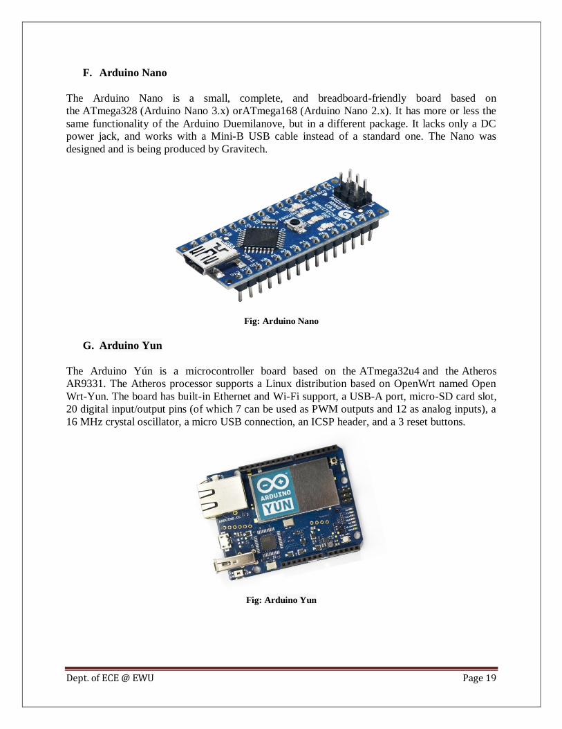
F. Arduino Nano
The Arduino Nano is a small, complete, and breadboard-friendly board based on
the ATmega328 (Arduino Nano 3.x) orATmega168 (Arduino Nano 2.x). It has more or less the
same functionality of the Arduino Duemilanove, but in a different package. It lacks only a DC
power jack, and works with a Mini-B USB cable instead of a standard one. The Nano was
designed and is being produced by Gravitech.
Fig: Arduino Nano
G. Arduino Yun
The Arduino Yún is a microcontroller board based on the ATmega32u4 and the Atheros
AR9331. The Atheros processor supports a Linux distribution based on OpenWrt named Open
Wrt-Yun. The board has built-in Ethernet and Wi-Fi support, a USB-A port, micro-SD card slot,
20 digital input/output pins (of which 7 can be used as PWM outputs and 12 as analog inputs), a
16 MHz crystal oscillator, a micro USB connection, an ICSP header, and a 3 reset buttons.
Fig: Arduino Yun

Dept. of ECE @ EWU Page 20
The Arduino Shields:
Arduino Shields are boards that connect to a number of different Arduino models. They extend
the abilities of the basic board by adding features such as wireless network access, cell access, or
the ability to prototype circuits.
A. Wireless Shields
The wireless-enabled shields for the Arduino come in two types. One, the Wi-Fi Shield, allows
the board to access the Internet through an 802.11 b/g-supported network and has a built-in
micro-SD card slot to host files accessible through the Internet or the network. The Wireless SD
Shield has an XBee module and enables communications between the Arduino and other XBee-
supported devices, including the Wireless Proto Shield.
Fig: Wireless Shields
B. The GSM Shield
The Arduino GSM Shield connects your Arduino to the internet using the GPRS wireless
network. Just plug this module onto your Arduino board, plug in a SIM card from an operator
offering GPRS coverage and follow a few simple instructions to start controlling your world
through the internet. You can also make/receive voice calls (you will need an external speaker
and microphone circuit) and send/receive SMS messages. There are different type of GSM shield
like SIM900, Sim900A,SIM808 etc.
Fig: Different Types of GSM Shield

Dept. of ECE @ EWU Page 21
C. The Ethernet Shield
Description: The Arduino Ethernet Shield 2 allows an Arduino Board to connect to the Internet.
It is based on the Wiznet W5500 Ethernet chip. The Wiznet W5500 provides a network (IP)
stack capable of both TCP and UDP. It supports up to eight simultaneous socket connections.
Fig: Ethernet Shield
D. The Proto Shields
These shields allow users to practice or "breadboard" their designs without needing to solder
anything. There is the Wireless Proto Shield and the Proto Shield available. The Wireless Proto
Shield uses the XBee chip to communicate with other devices, while the Proto Shield connects
directly to the Arduino board. They support through-hole integrated circuits as well as surface
mount integrated circuit.
Fig:”

Dept. of ECE @ EWU Page 22
2.2.3 Advantages and Disadvantages of Arduino
In last years’ the use of Arduino increases exponentially due to its readability and easiness.
Arduino has some advantages and some disadvantages:
Advantages:
Ready to Use: The biggest advantage of Arduino is its ready to use structure. As Arduino
comes in a complete package form which includes the 5V regulator, a burner, an
oscillator, a micro-controller, serial communication interfaces LED and headers for the
connections.
Examples of codes: Another big advantage of Arduino is its library of examples present
inside the software of Arduino. For example if we want to measure voltage using
ATmega8 micro-controller and want to display the output on computer screen then we
have to go through the whole process. The process will start from learning the ADC's of
micro-controller for measurement, went through the learning of serial communication for
display and will end at USB - Serial converters.
Effortless functions: During coding of Arduino, we will notice some functions which
make the life so easy. Another advantage of Arduino is its automatic unit conversion
capability. We can say that during debugging we don't have to worry about the units
conversions.
Large community: There are many forums present on the internet in which people are
talking about the Arduino. Engineers, hobbyists and professionals are making their
projects through Arduino. You can easily find help about everything. Moreover the
Arduino website itself explains each and every functions of Arduino.
Disadvantages:
Structure: The structure of Arduino is its disadvantage as well. During building a project
you have to make its size as small as possible. But with the big structures of Arduino we
have to stick with big sized PCB’s. If we are working on a small micro-controller like
ATmega8 we can easily make our PCB as small as possible.
Cost: The most important factor which you cannot deny is cost. This is the problem
which every hobbyist, Engineer or Professional has to face. Now, we must consider that
the Arduino is cost effective or not.

Dept. of ECE @ EWU Page 23
Chapter-3
HARDWARE & SOFTWARE
3.1 Hardware
Hardware is the physical parts or components of the system. In this project work, we’ve used
some hardwares Arduino, GSM, Relay, switch, transformer etc.
3.1.1 Block Diagram and Description
Fig: Block Diagram of Full Project
In this project Arduino is used for controlling the whole process. Arduino is interfaced with
commands supporting GSM module. The user at a remote place sends SMS to control the home
appliances. After receiving given commands by Arduino through GSM, Arduino send signal to
relays, to switch ON or OFF the home appliances using a relay driver.
When we send SMS to GSM module by Mobile, then GSM receives that SMS and sends it to
Arduino. Now Arduino reads this SMS and extract main command from the received string and
stores in a variable. After this, Arduino compare this string with predefined string. If match
occurred then Arduino sends signal to relay via relay driver for turning ON and OFF the home
appliances.

Dept. of ECE @ EWU Page 24
The methodology followed in our Home Appliance Control System is as follows:
GSM hardware tests are run in order to check the hardware support. The system calls GSM
modem and it get activated.
After activation the Modem checks for hardware support. If the hardware is missing or
some other hardware problem there is error, resulting in communication failure and the
application is terminated.
If hardware responds then the serial port is opened for communication and GSM hardware
allows transmission of SMS.
The system is then connected and after connection establishment the system is able to
switch ON and OFF and similarly the system will update status of appliances by receiving
SMS from the pre-defined cell number.
Required Equipments:
i. Arduino UNO
ii. SIM 808 Module
iii. 4-Channel 5V Relay Shield
iv. Relay Driver ULN2003A
v. Water Level Indicator
vi. Dc 5V Motor(for making mini water pump)
vii. Load (220V/60W Bulb-3Pcs)
viii. 12V/2A Adapter
ix. Bread Board
x. Some Jumpers & Wires
xi. Other equipments which is required to make the module
(like soldering iron, driver, glue etc )
3.1.2 Arduino UNO
The Uno is a microcontroller board based on the ATmega328P. It has 14 digital input/output pins
in which 6 can be used as PWM outputs, 6 analog inputs, a 16 MHz quartz crystal, a USB
connection, a power jack, an ICSP header and a reset button. It contains everything needed to
support the microcontroller. Simply connect it to a computer with a USB cable or power it with a
AC-to-DC adapter or battery to get started.

Dept. of ECE @ EWU Page 25
Fig: Arduino UNO
Technical Specs:

Dept. of ECE @ EWU Page 26
Memory:
The ATmega328 has 32 KB (with 0.5 KB occupied by the bootloader). It also has 2 KB of
SRAM and 1 KB of EEPROM (which can be read and written with the EEPROM library).
Pin Mode:
Each of the 14 digital pins on the Uno can be used as an input or output, using pinMode(),
digitalWrite(), and digitalRead() functions. They operate at 5 volts. Each pin can provide or
receive 20 mA as recommended operating condition and has an internal pull-up resistor
(disconnected by default) of 20-50k ohm. A maximum of 40mA is the value that must not be
exceeded on any I/O pin to avoid permanent damage to the microcontroller.

Dept. of ECE @ EWU Page 27
In addition, some pins have specialized functions:
I. Serial: 0 (RX) and 1 (TX). Used to receive (RX) and transmit (TX) TTL serial data.
These pins are connected to the corresponding pins of the ATmega8U2 USB-to-TTL
Serial chip.
II. External Interrupts: 2 and 3. These pins can be configured to trigger an interrupt on a low
value, a rising or falling edge, or a change in value. See the attachInterrupt () function for
details.
III. PWM: 3, 5, 6, 9, 10, and 11. Provide 8-bit PWM output with the analogWrite () function.
IV. SPI: 10 (SS), 11 (MOSI), 12 (MISO), 13 (SCK). These pins support SPI communication
using the SPI library.
V. LED: 13. There is a built-in LED driven by digital pin 13. When the pin is HIGH value,
the LED is on, when the pin is LOW, it's off.
VI. TWI: A4 or SDA pin and A5 or SCL pin. Support TWI communication using the Wire
library.
Communication:
The Uno has a number of facilities for communicating with a computer, another Uno board, or
other microcontrollers. The ATmega328 provides UART TTL (5V) serial communication, which
is available on digital pins 0 (RX) and 1 (TX). An ATmega16U2 on the board channels this
serial communication over USB and appears as a virtual com port to software on the computer.
The 16U2 firmware uses the standard USB COM drivers, and no external driver is needed.
However, on Windows, a .inf file is required. The Arduino Software (IDE) includes a serial
monitor which allows simple textual data to be sent to and from the board. The RX and TX
LEDs on the board will flash when data is being transmitted via the USB-to-serial chip and USB
connection to the computer (but not for serial communication on pins 0 and 1).
3.1.3 4-Channel 5V Relay Shield
Relay is an electromagnetic device which is used to isolate two circuits electrically and connect
them magnetically. They are very useful devices and allow one circuit to switch another one
while they are completely separate. A relay is also an electrically operated switch. It is mainly
used to control higher voltage circuits with lower voltage. For example, a relay can make a 5V

Dept. of ECE @ EWU Page 28
DC battery circuit to switch a 230V AC mains circuit. Thus a small sensor circuit can drive, say
a fan or an electric bulb.
Fig: 4-Channel 5V Relay Shield
A relay switch can be divided into two parts: input and output. The input section has a coil
which generates magnetic field when a small voltage from an electronic circuit is applied to it.
This voltage is called the operating voltage. Commonly used relays are available in different
configuration of operating voltages like 5V, 6V, 9V, 12V, 24V etc. The output section consists
of contactors which connect or disconnect mechanically.
In a basic relay there are three contactors:
1. Normally-Open (NO): The circuit is disconnected i.e. open
when the relay is inactive.
2. Normally-Closed (NC): The circuit is connected i.e. closed
when the relay is inactive.
3. Common (COM): This is the common port which is
normally connect with NC in inactive mode and in active
mode it is connected with NO
At no input state, the COM is connected to NC. When the operating voltage is applied the relay
coil gets energized and the COM changes contact to NO. To connect with the load with the relay
at first we have to connect the direct power to the load and another connection has to connect
with COM and another connection of load will connect with NO. And if we want to add the
switch board with the relay shield then the connection will be the same way with the switch
board. The Relay Shield is an Arduino compatible smart module with 4 mechanical relays
providing an easy way to control high voltage.

Dept. of ECE @ EWU Page 29
Fig: Schematic diagram of Relay
Connection between Relay, Manual switch & Load:

Dept. of ECE @ EWU Page 30
3.1.4 Relay Driver ULN2003A
ULN2003A is a high voltage and high current Darlington array IC. It contains seven open
collector darlington pairs with common emitters. A darlington pair is an arrangement of two
bipolar transistors. Darlington transistors capable of 500mA, 50V output. The ULN2003 is
known for its high-current, high-voltage capacity. ULN2003 is for 5V TTL, CMOS logic
devices. It can also be used for interfacing with a stepper motor.
The schematic for each driver is given below:
Fig: ULN2003A pin out

Dept. of ECE @ EWU Page 31
3.1.5 SIM 808 Module
SIM808 module is a GSM and GPS two-in-one function module. It is based on the latest
GSM/GPS module SIM808 from SIMCOM, supports GSM/GPRS Quad-Band network and
combines GPS technology for satellite navigation. It has high GPS receive sensitivity with 22
tracking and 66 acquisition receiver channels. Besides, it also supports A-GPS that available for
indoor localization. The module is controlled by AT command via UART and supports 3.3V and
5V logical level.
Fig: GSM SIM808
SIM 808 Key Features:
Feature Implementation
Power supply 3.4V ~ 4.4V
Frequency band SIM808 Quad-band:GSM 850,EGSM 900,
DCS 1800,PCS 1900MHz
Power saving Typical power consumption in sleep mode is
1.07 mA
GPRS connectivity GPRS multi-slot class 12(default)
GPRS multi-slot class 1~12
(optional)
Temperature range Normal operation:-40°C~ +85°C
Storage temperature -45°C~ +90°C
Dimensions 24.0*24.0*2.6mm
Command Control via AT commands
SIM supported Standard Micro SIM Card

Dept. of ECE @ EWU Page 32
Interface Function:
GPS Antenna: This is an uFL GPS antenna connector. You can connect either passive or
active GPS antenna to it. Active GPS antenna runs at 2.8V voltage.
MicroUSB: The charging interface for Li-Ion battery, of input voltage range from 5V to
7V. Besides, it is also the software debugging interface for SIM808 that you can upgrade
firmware and debug software.
Power Button: This is the hard power switch for the module. When the module is power
up, you can turn on or turn off the module by pressing the button for 2s.
Net Indicator: Red LED, it will tell them what status is about the module linking to
network.
Status Indicator: Green LED, it will tell whether the module is on, light when the module
is running.
Li-ion Battery: This is power supply for the module; input voltage is from 3.4V to 4.4V.
It uses the XH-2.0mm connector that makes it convenient to connect to 3.7V Li-Po
Battery.
GSM Antenna: This is an uFL GSM antenna connector; just connect it to a GSM antenna
for receiving GSM signal.
SIM - Card Holder: SIM card holder for standard SIM card.
Microphone: This is the reserved interface for 2.8V microphone. By using the
microphone, you can make voice calls and collect speech data around the module.
VRTC: RTC backup. You can add external capacitor or rechargeable battery on it

Dept. of ECE @ EWU Page 33
SIM 808 PIN Diagram:
Fig: SIM808 Pin Diagram
3.1.6 Water Level Indicator
This simple transistor based water level indicator circuit is very useful to indicate the water
levels in a tank. Whenever tank gets filled, we get alerts on particular levels. Here we have
created 2 levels (low, full). We have added 2 LEDs to indicate initial two levels low (Green
LED) and high (Red LED). When Green LED glow it sends signal to the pin mode 12 of the
Arduino. When Yellow LED glows it sends signal to the pin mode 13 of the Arduino.
Circuit Components:
a) BC547 Transistors -2 pcs
b) Resistors 330 -2 pcs
c) Color LED -2 pcs
d) 9V Battery Battery clip

Dept. of ECE @ EWU Page 34
Diagram of Water Level Indicator:
Fig: Circuit diagram of Water level Indicator
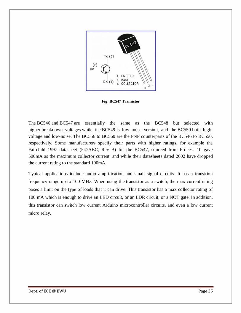
BC547 Transistor:
A BC547 transistor is a negative-positive-negative (NPN) transistor that is used for many
purposes. Together with other electronic components, such as resistors, coils, and capacitors, it
can be used as the active component for switches and amplifiers. NPN transistors, this type has
an emitter terminal, a base or control terminal, and a collector terminal. In a typical
configuration, the current flowing from the base to the emitter controls the collector current.
There are various types of transistors, and the BC547 is a bipolar junction transistor (BJT). There
are also transistors that have one junction, such as the junction field-effect transistor, or no
junctions at all, such as the metal oxide field-effect transistor (MOSFET). The negative (N)-type
material inside an NPN transistor has an excess of electrons, while the positive (P)-type material
has a lack of electrons, both due to a contamination process called doping.
Dept. of ECE @ EWU Page 35
Fig: BC547 Transistor
The BC546 and BC547 are essentially the same as the BC548 but selected with
higher breakdown voltages while the BC549 is low noise version, and the BC550 both high-
voltage and low-noise. The BC556 to BC560 are the PNP counterparts of the BC546 to BC550,
respectively. Some manufacturers specify their parts with higher ratings, for example the
Fairchild 1997 datasheet (547ABC, Rev B) for the BC547, sourced from Process 10 gave
500mA as the maximum collector current, and while their datasheets dated 2002 have dropped
the current rating to the standard 100mA.
Typical applications include audio amplification and small signal circuits. It has a transition
frequency range up to 100 MHz. When using the transistor as a switch, the max current rating
poses a limit on the type of loads that it can drive. This transistor has a max collector rating of
100 mA which is enough to drive an LED circuit, or an LDR circuit, or a NOT gate. In addition,
this transistor can switch low current Arduino microcontroller circuits, and even a low current
micro relay.
Dept. of ECE @ EWU Page 36
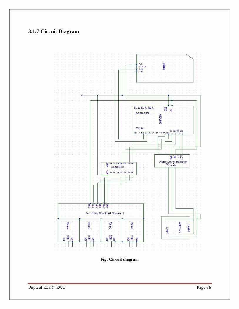
3.1.7 Circuit Diagram
Fig: Circuit diagram
Dept. of ECE @ EWU Page 37
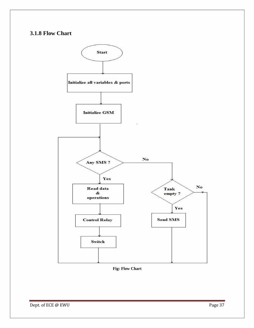
3.1.8 Flow Chart
Fig: Flow Chart

Dept. of ECE @ EWU Page 38
3.2 Software
Arduino is an open-source platform used for building electronics projects. The Arduino
Integrated Development Environment or Arduino Software (IDE) contains a text editor for
writing code, a message area, a text console, a toolbar with buttons for common functions and a
series of menus. It connects to the Arduino and Genuine hardware to upload programs and
communicate with them. The Arduino programming language (based on Wiring), and the
Arduino Software (IDE), based on Processing. The Arduino IDE uses a simplified version of
C++, making it easier to learn to program. There are two types of commands – AT command and
GSM library
3.2.1 AT Command
These commands are used to control MODEMs. AT is the abbreviation for Attention. These
commands come from Hayes commands that were used by the Hayes smart modems. The Hayes
commands started with AT to indicate the attention from the MODEM. The dial up and wireless
MODEMs (devices that involve machine to machine communication) need AT commands to
interact with a computer. These include the Hayes command set as a subset, along with other
extended AT commands.
AT commands with a GSM/GPRS MODEM or mobile phone can be used to access following
information and services:
1. Information and configuration pertaining to mobile device or MODEM and SIM
card.
2. SMS services.
3. MMS services.
4. Fax services.
5. Data and Voice link over mobile network.
3.2.2 GSM Library
GSM library is a default code in Arduino software. The GSM library is included with Arduino
IDE 1.0.4 and later. With the Arduino GSM Shield, this library enables an Arduino board to do
most of the operations you can do with a GSM phone: place and receive voice calls, send and
receive SMS, and connect to the internet over a GPRS network.
The GSM shield has a modem that transfers data from a serial port to the GSM network. The
modem executes operations via a series of AT commands. The library abstracts low level
communications between the modem and SIM card. It relies on the Software Serial library for
communication between the modem and Arduino.
Dept. of ECE @ EWU Page 39
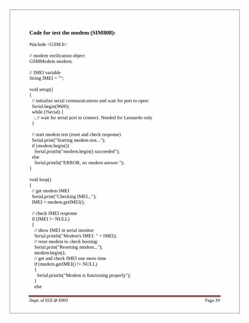
Code for test the modem (SIM808):
#include <GSM.h>
// modem verification object
GSMModem modem;
// IMEI variable
String IMEI = "";
void setup()
{
// initialize serial communications and wait for port to open:
Serial.begin(9600);
while (!Serial) {
; // wait for serial port to connect. Needed for Leonardo only
}
// start modem test (reset and check response)
Serial.print("Starting modem test...");
if (modem.begin())
Serial.println("modem.begin() succeeded");
else
Serial.println("ERROR, no modem answer.");
}
void loop()
{
// get modem IMEI
Serial.print("Checking IMEI...");
IMEI = modem.getIMEI();
// check IMEI response
if (IMEI != NULL)
{
// show IMEI in serial monitor
Serial.println("Modem's IMEI: " + IMEI);
// reset modem to check booting:
Serial.print("Resetting modem...");
modem.begin();
// get and check IMEI one more time
if (modem.getIMEI() != NULL)
{
Serial.println("Modem is functoning properly");
}
else

Dept. of ECE @ EWU Page 40
{
Serial.println("Error: getIMEI() failed after modem.begin()");
}
}
else
{
Serial.println("Error: Could not get IMEI");
}
// do nothing:
while (true);
}
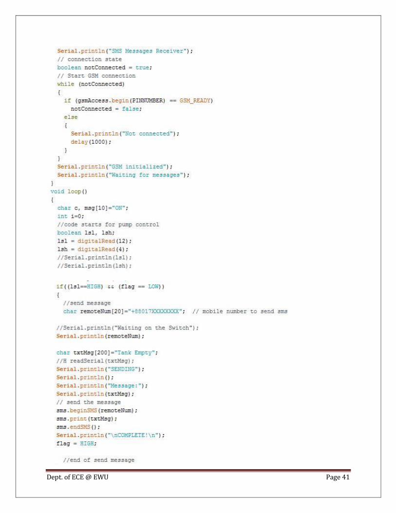
3.2.3 Coding
Dept. of ECE @ EWU Page 41

Dept. of ECE @ EWU Page 42

Dept. of ECE @ EWU Page 43

Dept. of ECE @ EWU Page 44
Chapter-4
RESULTS & DISCUSSIONS
4.1 Hardware Results
The model is designed in bread board and all the components are connected as per the circuit
diagram. The figures below shows the hardware connection and the output obtained.
Step 1: When no message is sent

Dept. of ECE @ EWU Page 45
Step 2: When message is sent

Dept. of ECE @ EWU Page 46
4.2 Discussions
SMS based home appliance control system is capable of controlling of the appliances from any
place where GSM service is available. The combination of the hardware and software give the
final design.
There were some problems encountered in our project development which can be stated as
under:
The modem with our mobile does not support most of the AT
Commands.
Problem with device deployment in laptops with 64-bit Operating
System.
Unavailability of components in the local market.
We have facing many problems for using GSM SIM 900
Coding issues also creates some problems.
Configuration words had to be properly crosschecked for burning
the code in the microcontroller.

Dept. of ECE @ EWU Page 47
Chapter-5
CONCLUTION
5.1 Conclusion In this project a low-cost and simple approach to design an intelligent home system using the
concept of mobile-to-machine and machine-to-mobile communication is designed. We develop a
general purpose electronic circuit design that can control and monitor a variety of home
appliances with interface that can be plugged into GSM modem. The project is successfully
developed and met the stated objectives. The system can automatically switch ON and OFF the
devices remotely using SMS. In addition, the system is very practical when the user is away from
home; through it the user can control the electrical home appliances remotely as long as the
mobile phone gets the coverage. The whole control system is protected by password that is why
unauthorized users will not be able to control this system.
5.2 Future Work Scope
Smart home technology is one of the emerging technologies in the technological world.
Face & finger detector door controller using SMS & MMS
SMS controlled fridge with the consumer interface
Windows & curtain controller by using SMS
Adjust/regulate light intensity, fan & AC power using SMS
5.3 Product Commercialization
After completing all the circuit and developing the control system, we connected this control
system in a room and we can see that it works properly. Therefore, we can say that our designed
and developing control system is ready for commercial uses. We can assure that the setup cost of
this control system is reasonable.

Dept. of ECE @ EWU Page 48
BIBLIOGRAPHY
[1] B. Woodward, H. Istepamian, and C. Richards, “Design of a Telemedicine system using a
mobile telephone”, IEEE Transaction on Information Technology in Biomedicine, vol, 5, no. 1,
March 2001.
[2] H. Sang, C. Lin, and Z. Youn, "A wireless Internet-based measurement architecture for air
quality monitoring",IEEE Conference Instrumentation and Measurement Technology, IMTC 04,
May, 2004
[3] Tan, H.G.R. Lee, C.H.R. Mok, V.H. (2007). “Automatic Power Meter Reading System using
GSM Network.” In Proceeding on Power Engineering Conference 2007. 3-6 Dec 2007, Kuala
Lumpur, pp. 465-469.
[4] Mohd Helmy Abd Wahab, Siti Zarina Mohd Muji, Fazliza Md. Nazir. Integrated Billing
System through GSM Network. In Proceeding of 3rd International Conference on Robotics,
Vision, Information and Signal Processing 2007 (ROVISP2007), Penang, Malaysia, 28– 30
November 2007.
[5] Mohd Noor Bin Abdullah (2008). “Acquiring Water Level and Temperature Status via
SMS.”Universiti Tun Hussein Onn Malaysia: Thesis Sarjana Muda.
[6]Lock K.A (2004). “Remote and Security Control Via SMS.” Kolej Universiti Tun Hussein
Onn Malaysia:Thesis Sarjana Muda.

Dept. of ECE @ EWU Page 49
REFERENCES
https://www.fairchildsemi.com/datasheets/BC/BC547.pdf
https://www.arduino.cc/en/Reference/GSM
https://www.arduino.cc/en/Main/ArduinoBoardYun
https://www.google.com/url?sa=t&rct=j&q=&esrc=s&source=web&cd=1&cad=rja&uact
=8&ved=0ahUKEwi3hIS4yp_LAhXTkI4KHc6LClsQFggdMAA&url=http%3A%2F%2
Fwww.slideshare.net%2Folafusimichael%2F500project1&usg=AFQjCNGoeWJ-
HkJRwlSh6ukZ8wHJ2cyBuA
https://www.google.com/url?sa=t&rct=j&q=&esrc=s&source=web&cd=3&cad=rja&uact
=8&ved=0ahUKEwi3hIS4yp_LAhXTkI4KHc6LClsQFggrMAI&url=https%3A%2F%2F
www.scribd.com%2Fdoc%2F35146915%2FProject-Final-Report-On-Home-
Automation&usg=AFQjCNHBz3JrQJHNaqdk2YBwsDX4XhVFJQ
https://www.arduino.cc/
https://learn.sparkfun.com/tutorials/what-is-an-arduino
http://www.howtogeek.com/65963/what-is-arduino/
http://www.engineersgarage.com/electronic-components/relays
http://www.engineersgarage.com/electronic-components/uln2003-datasheet
http://www.simcom.ee/modules/gsm-gprs-gnss/sim808/