passive design for rfog networks - scte piedmont …chapter_rfog+design_1… · passive design for...
TRANSCRIPT
Passive Design for RFoG NetworksMark ConnerMarket Development Manager – Access18 March 2009SCTE Piedmont Chapter Meeting
2Corning Incorporated
REMEMBER:
RFoG is a work in progress
It has come a long way
But it has not been through balloting
Many parameters are still being worked through
Agenda• Why all-fiber access?• RFoG overview
– What and why RFoG?– Network elements– A look at the R-ONU– Compare to GPON and EPON
• All-fiber access– Architectures– Current deployment methods– Migration

3Corning Incorporated
What All-Fiber?• Bandwidth supply/demand• Competition• Reduce operating costs• In greenfield deployments, reduce long term total cost
– Avoids major rebuild by deploying fiber first• All-fiber access can be a universal strategy
– Commercial– Residential

4Corning Incorporated
Bandwidth – Movin’ On Up!
Data Source: FCC. Speeds are based on DSL & FTTL data. Excludes mobile w ireless broadband
0%
10%
20%
30%
40%
50%
60%
70%
80%
90%
100%
1995 2000 2005 2010 2015 2020 2025Year
Perc
enta
ge o
f Hou
seho
lds
1.5Mb/s
6 Mb/s
24 Mb/s
100 Mb/s& Above
All Broadband Households
Source: Technology Futures, Inc.
2008Broadband Access 50 Mb/s
Data Source: FCC. Speeds are based on DSL & FTTL data. Excludes mobile w ireless broadband
1.5 - 6 Mbps widespread
now
1.5 - 6 Mbps widespread
now
Today +5 yrs
Beyond 5 yrs, 100+ Mbps becomes
widest used service; others
fade
Mix of 6, 24, 50, 100 Mbps
in 5 yrs
FTTH Council Industry Update Webinar 2008

5Corning Incorporated
What & Why RFoG?• RFoG is …
– All-fiber access technology that leverages fiber to the subscriber and is compatible with the MSO back office / equipment
• RFoG leverages the MSO framework– Same headend gear– Same CPE– Designed to allow co-existent overlays
• RFoG simplifies & reduces costs such as …– Minimizes/eliminates system power bills, outages due to power
failures– No “adjustments” needed in the outside plant (i.e. amp balancing)– Eliminates annual proof performance (fly-overs, leakage testing)– Return path ingress issues no longer apply

6Corning Incorporated
What are the RFoG Elements?
Headend ODN Subscriber
Source: SCTE
1550 nm
1310 or 1610 nm
Rest of headend(CMTS, etc.)
54 -1,002 MHz
5 - 42 MHz
WDM
Other RFoG and HFC networks
. . . Split 32X
Standard CPE
R-ONU
R-ONU

7Corning Incorporated
What are the RFoG Elements?
1490 nm Down data1310 nm Up data
1550 nm
Rest of headend
54 -1,002 MHz
ONT
ONT
WDM
Switch OLT (no CMTS used)
Other RFoG and HFC networks
Still 1550 nm down, except no DOCSIS component
RF looks like HFC, data on 10/100/1000Base-T, POTS
Source: SCTE. .
. Split 32X
Headend ODN Subscriber

8Corning Incorporated
R-ONU Close-Up
Source: SCTE
ODN `
CM /eMTA
RF detector
R-ONU
WDM
9Corning Incorporated
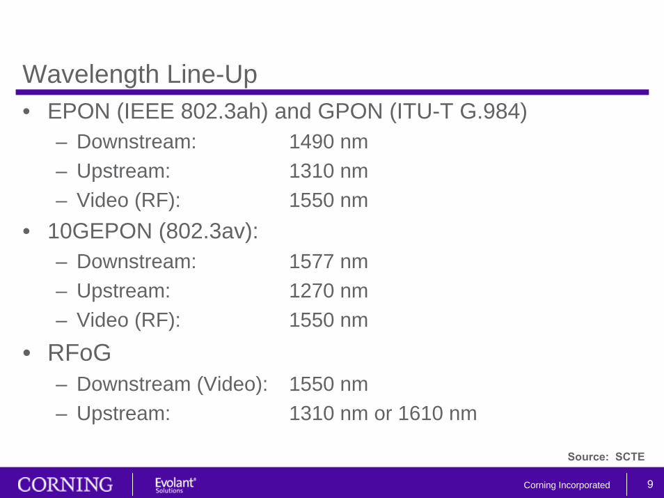
Wavelength Line-Up• EPON (IEEE 802.3ah) and GPON (ITU-T G.984)
– Downstream: 1490 nm– Upstream: 1310 nm– Video (RF): 1550 nm
• 10GEPON (802.3av):– Downstream: 1577 nm– Upstream: 1270 nm– Video (RF): 1550 nm
• RFoG– Downstream (Video): 1550 nm– Upstream: 1310 nm or 1610 nm
Source: SCTE
10Corning Incorporated
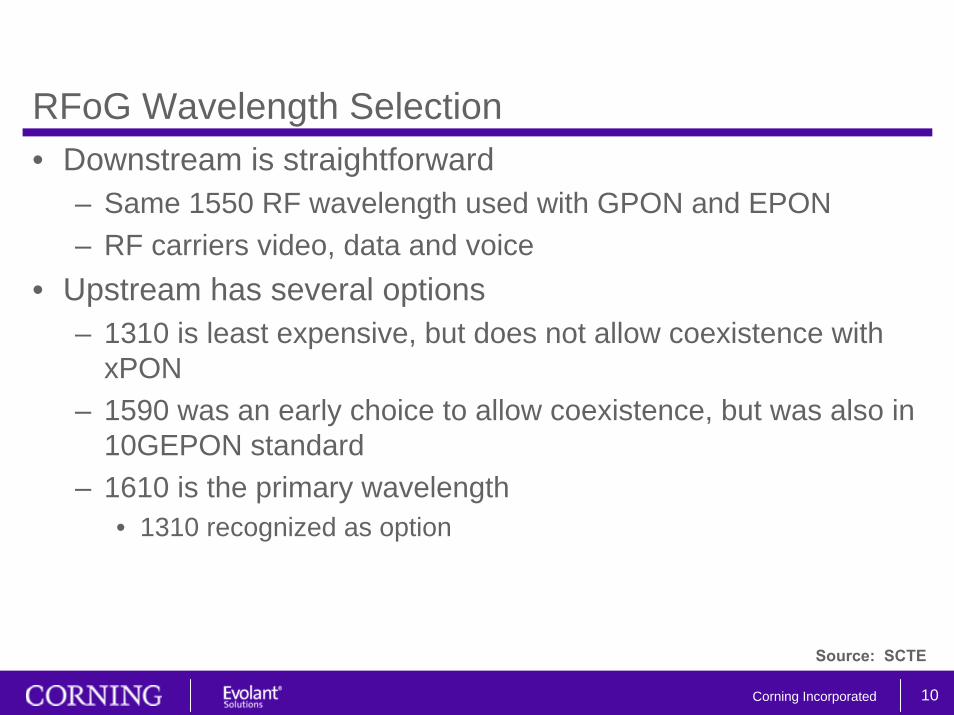
RFoG Wavelength Selection• Downstream is straightforward
– Same 1550 RF wavelength used with GPON and EPON– RF carriers video, data and voice
• Upstream has several options– 1310 is least expensive, but does not allow coexistence with
xPON– 1590 was an early choice to allow coexistence, but was also in
10GEPON standard– 1610 is the primary wavelength
• 1310 recognized as option
Source: SCTE
11Corning Incorporated
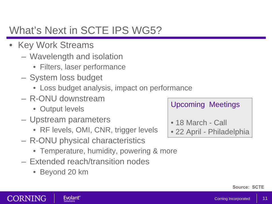
What’s Next in SCTE IPS WG5?• Key Work Streams
– Wavelength and isolation• Filters, laser performance
– System loss budget• Loss budget analysis, impact on performance
– R-ONU downstream• Output levels
– Upstream parameters• RF levels, OMI, CNR, trigger levels
– R-ONU physical characteristics• Temperature, humidity, powering & more
– Extended reach/transition nodes• Beyond 20 km
Upcoming Meetings
• 18 March - Call• 22 April - Philadelphia
Source: SCTE

12Corning Incorporated
• RFoG Architectures• HFC to All-Fiber Cross Reference• All-Fiber Architectural Models
Mapping from HFC to All-Fiber
13Corning Incorporated
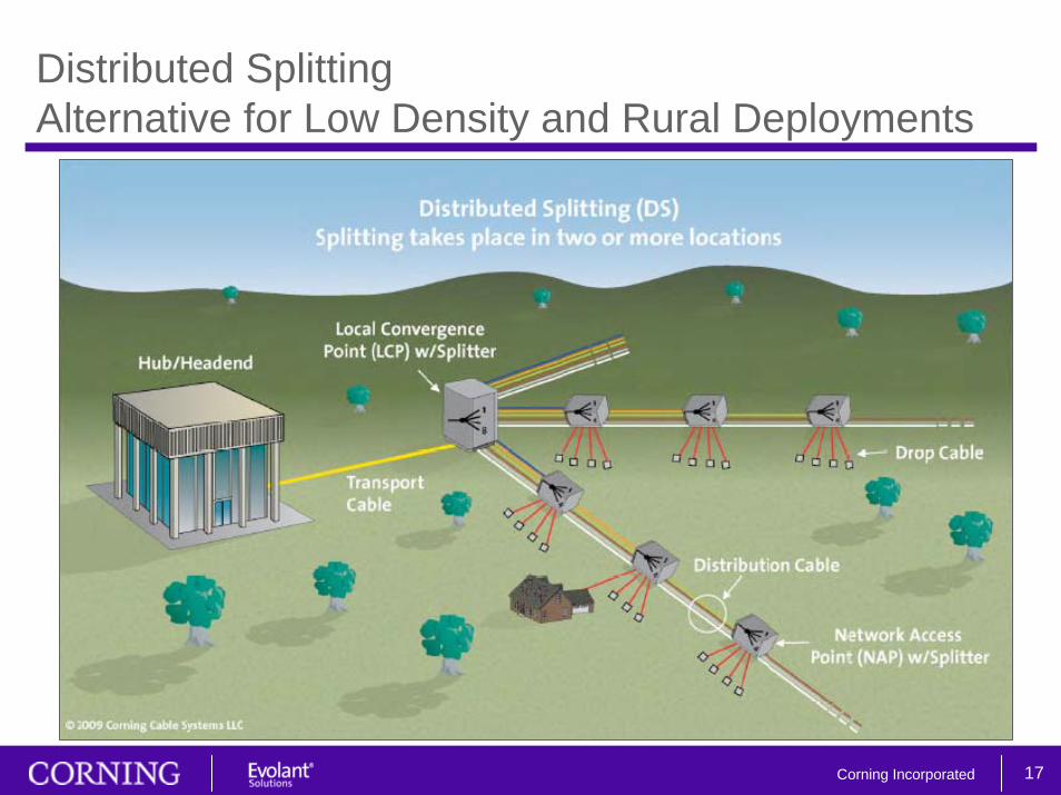
RFoG Architectures• RFoG is architecturally agnostic• ‘Optical Hub’
– All electronics at head end means all-passive network– Some electronics in the field – all-fiber, but not
all-passive network• Key is the link specification
– Loss budget (28 dB)– Reach (20 km)– Connectors (APC)
• Three main Splitting Strategies– Home Run (head end)– Centralized (field concentration point)– Distributed (multiple field locations)
14Corning Incorporated
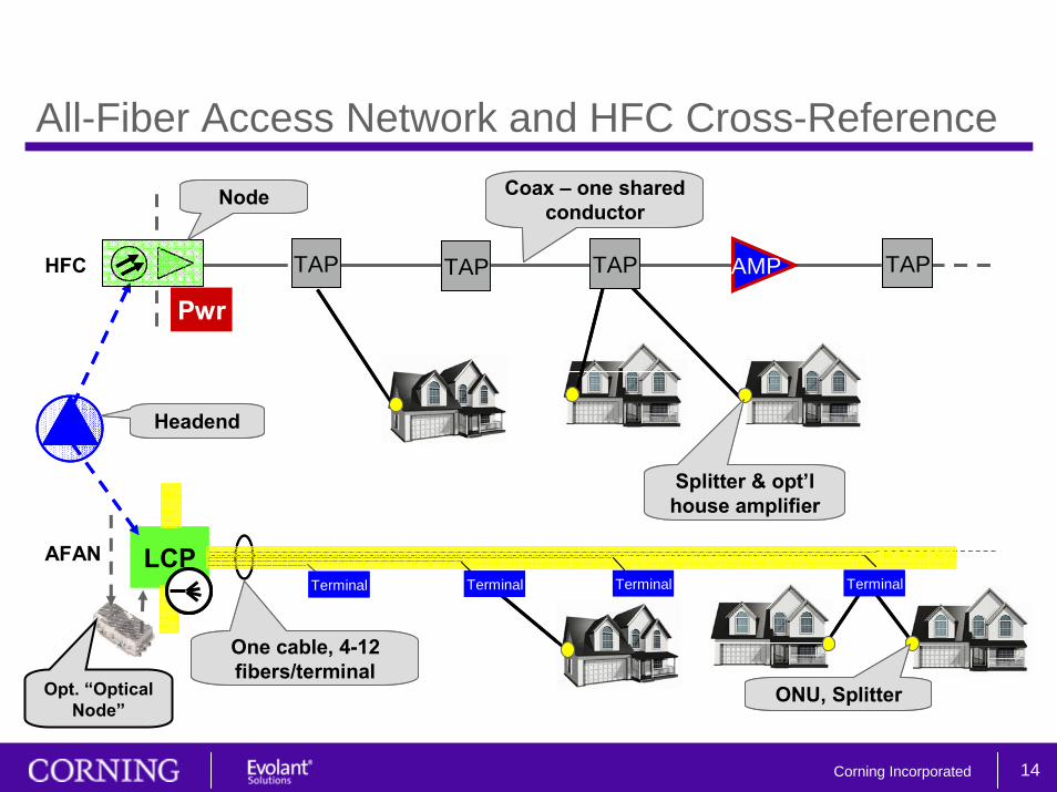
All-Fiber Access Network and HFC Cross-Reference
AMP
Pwr
LCP
Coax – one shared conductor
One cable, 4-12 fibers/terminal
HFC
AFANTerminal Terminal Terminal Terminal
Splitter & opt’lhouse amplifier
ONU, Splitter
TAP TAP TAP TAP
Headend
Node
AMP
Pwr
LCP
Coax – one shared conductor
One cable, 4-12 fibers/terminal
HFC
AFANTerminal Terminal Terminal Terminal
Splitter & opt’lhouse amplifier
ONU, Splitter
TAP TAP TAP TAP
Headend
Node
Opt. “Optical Node”

15Corning Incorporated
Headend - Home RunConsidered for Smaller Deployments
16Corning Incorporated
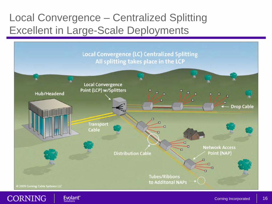
Local Convergence – Centralized SplittingExcellent in Large-Scale Deployments
17Corning Incorporated
Distributed SplittingAlternative for Low Density and Rural Deployments
18Corning Incorporated
• Bottoms-up Methodology• Port Count & Drop Length
Design
19Corning Incorporated
Bottoms-up Methodology1. Define network access point (NAP) groups
– Strive for symmetry and uniform size (“fours”)– Minimize drop length (reduce drop labor and material)
2. Join NAPs into distribution cables– Minimize number of cables (reduce placement cost)– Right-size fiber counts
3. Define local convergence point (LCP) service areas– Use multiple LCPs – small service areas– Small areas minimize cable lengths and fiber counts– Allocate space for future network growth
4. Determine transport path
20Corning Incorporated
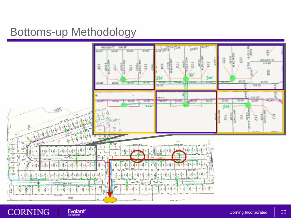
Bottoms-up Methodology
21Corning Incorporated
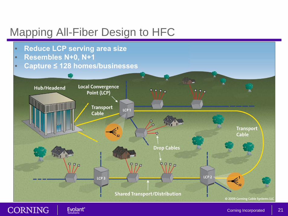
Mapping All-Fiber Design to HFC• Reduce LCP serving area size• Resembles N+0, N+1• Capture ≤ 128 homes/businesses
22Corning Incorporated
• RFoG Only• Overlay• Managing the Network• Residential & Commercial Services
Deployment Scenarios
23Corning Incorporated
RFoG & More• Initial deployment as RFoG only
– Standard RF capability– Voice, video and data– DOCSIS 2.0 or 3.0
• Overlay with EPON, GPON or 10G version– xPON adds data capacity– Coexists w/RFoG– RF continues to deliver video, voice– Commercial and residential opportunities
• Evolutionary Scenarios– Low cost & swap– Pre-provision (wavelength, expansion port)– Premium – all upfront
24Corning Incorporated
Managing Evolution• Objectives
– Subscriber management • Requires only basic skills – no splicing• Migration to expanded data in one truck roll
– Technology migration• Change just the active devices at the ends
– Change from optical splitting to wavelength multiplexing • Subscriber location• One field location
25Corning Incorporated
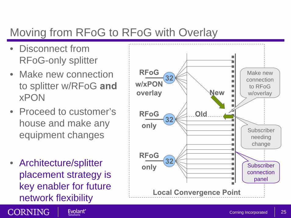
Moving from RFoG to RFoG with Overlay• Disconnect from
RFoG-only splitter• Make new connection
to splitter w/RFoG andxPON
• Proceed to customer’s house and make any equipment changes
• Architecture/splitter placement strategy is key enabler for future network flexibility
32
32
32only
RFoG
RFoG
RFoG
only
w/xPONoverlay
Old
New
Subscriber needing change
Make new connection to RFoG w/overlay
Local Convergence Point
Subscriber connection
panel

26Corning Incorporated
Migration• Leverage existing fibers to extend all-fiber services
– Requires one fiber per 32 homes OR
– add local hub in the case of limited fiber availability• HFC first, all-fiber future
– Provision at least one fiber per 32 homes passed– Build distribution from node to homes– Convert node to LCP
27Corning Incorporated
Conclusion• RFoG leverages existing MSO equipment while building an
all-fiber foundation• Eliminate/minimize powering, testing and maintenance costs• Select splitting architecture for best flexibility• Build once; design to standard passive parameters• Evolve capacity through technology overlay
– EPON, GPON; future 10GEPON, 10GPON– Residential and commercial
• Program for migration – provision optical fibers for all-fiber access