parts replacement pro cabinet - foster web spares
TRANSCRIPT

1
5.2 Parts Replacement Pro Cabinet.
Top Mount and Undermount Pro Cabinets.
IMPORTANT- all repairs must be carried out with the mains electrical supply disconnected and by acompetent person. Failure to do so may invalidate the warrantry.
5.2.1. Access To Electrical Connections All Models.Remove the front cover, containing the controller, using both hands and with a sharp forward motion pull itaway from the front of the cabinet. Once it is disengaged from the cabinet, unplug the ribbon cables from thePower Switching Unit (PSU) (see Fig 1)Remove the cover and place it in a safe place to avoid damage.
Fig 1. Power Switching Unit.
Remove the screws securing the PSU to the bracket on top mount refrigeration plug (See Fig 2A and 2B)and bottom mounts (See Fig 3), to gain access to the electrical connections. See Fig 1.
Fig 2A Single Section Top Mount Fig 2B Double Section Top Mount
To replace reverse the procedure ensuring that the PSU lid is fitted correctly, plug in the ribbon cables. Refitthe unit cover ensuring it is firmly located onto the retaining studs.
2
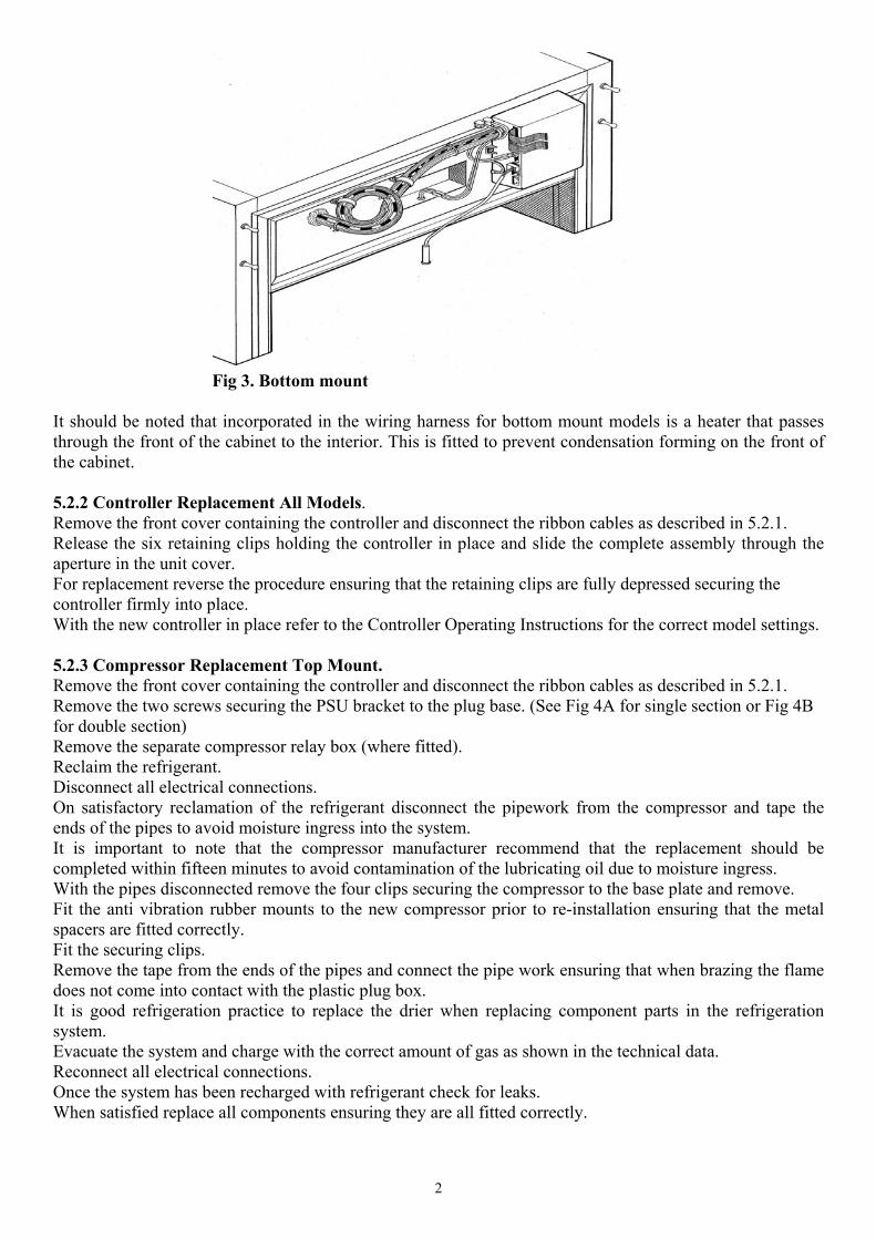
Fig 3. Bottom mount
It should be noted that incorporated in the wiring harness for bottom mount models is a heater that passesthrough the front of the cabinet to the interior. This is fitted to prevent condensation forming on the front ofthe cabinet.
5.2.2 Controller Replacement All Models.Remove the front cover containing the controller and disconnect the ribbon cables as described in 5.2.1.Release the six retaining clips holding the controller in place and slide the complete assembly through theaperture in the unit cover.For replacement reverse the procedure ensuring that the retaining clips are fully depressed securing thecontroller firmly into place.With the new controller in place refer to the Controller Operating Instructions for the correct model settings.
5.2.3 Compressor Replacement Top Mount.Remove the front cover containing the controller and disconnect the ribbon cables as described in 5.2.1.Remove the two screws securing the PSU bracket to the plug base. (See Fig 4A for single section or Fig 4Bfor double section)Remove the separate compressor relay box (where fitted).Reclaim the refrigerant. Disconnect all electrical connections. On satisfactory reclamation of the refrigerant disconnect the pipework from the compressor and tape theends of the pipes to avoid moisture ingress into the system. It is important to note that the compressor manufacturer recommend that the replacement should becompleted within fifteen minutes to avoid contamination of the lubricating oil due to moisture ingress. With the pipes disconnected remove the four clips securing the compressor to the base plate and remove.Fit the anti vibration rubber mounts to the new compressor prior to re-installation ensuring that the metalspacers are fitted correctly. Fit the securing clips.Remove the tape from the ends of the pipes and connect the pipe work ensuring that when brazing the flamedoes not come into contact with the plastic plug box. It is good refrigeration practice to replace the drier when replacing component parts in the refrigerationsystem. Evacuate the system and charge with the correct amount of gas as shown in the technical data. Reconnect all electrical connections. Once the system has been recharged with refrigerant check for leaks. When satisfied replace all components ensuring they are all fitted correctly.
3
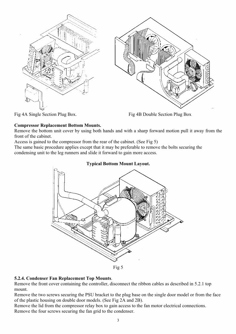
Fig 4A Single Section Plug Box. Fig 4B Double Section Plug Box
Compressor Replacement Bottom Mounts.Remove the bottom unit cover by using both hands and with a sharp forward motion pull it away from thefront of the cabinet.Access is gained to the compressor from the rear of the cabinet. (See Fig 5)The same basic procedure applies except that it may be preferable to remove the bolts securing thecondensing unit to the leg runners and slide it forward to gain more access.
Typical Bottom Mount Layout.
Fig 5
5.2.4. Condenser Fan Replacement Top Mounts.Remove the front cover containing the controller, disconnect the ribbon cables as described in 5.2.1 topmount.Remove the two screws securing the PSU bracket to the plug base on the single door model or from the faceof the plastic housing on double door models. (See Fig 2A and 2B).Remove the lid from the compressor relay box to gain access to the fan motor electrical connections.Remove the four screws securing the fan grid to the condenser.

4
To replace reverse the procedure ensuring that the all electrical connections are fully tightened, PSU lid isfitted correctly, and the unit cover is firmly located onto the retaining studs.Condenser Fan Replacement Bottom Mounts.Remove the bottom unit cover. Access is gained to the condensing unit from the rear of the cabinet. (See Fig 5)It may be preferable on some models to remove the bolts securing the condensing unit and slide it out togain more access.Removal of the fan motor follows the same procedure as the Top Mount Model.
5.2.5. Condenser Coil Replacement Top Mounts.Remove the front cover containing the controller and disconnect the ribbon cables as described in 5.2.1.Remove the two screws securing the PSU bracket to the plug base or the face of the plastic housing (See Fig2A and 2B).Reclaim the refrigerant. Remove the grid mount fan motor from the condenser as described in 5.2.4.On satisfactory reclamation of the gas disconnect the pipework from the condenser and tape the ends of thepipes to avoid moisture ingress into the system. It is important to note that the change over should be completed within fifteen minutes to avoid moistureabsorption into the compressor lubrication oil. Once the pipes have been disconnected remove the screws securing the condenser to the base plate andremove. Fit the replacement condenser. Remove the tape from the ends of the pipes and reconnect the pipe work ensuring that when brazing theflame does not come into contact with the plastic plug box. It is good practice to replace the drier when replacing component parts in the refrigeration system. Evacuate the system and charge with the correct amount of gas as shown in the technical data. Refit the fan. Once the system has been recharged with refrigerant check for leaks. When satisfied replace all components ensuring they are all fitted correctly.Condenser Coil Replacement Bottom Mounts.Remove the bottom unit cover. Access is gained to the condensing unit from the rear of the cabinet. (See Fig 5)It may be preferable on some models to remove the bolts securing the condensing unit and slide it out togain more access.Removal of the condenser coil follows the same procedure as the Top Mount Model.
5.2.6. Evaporator Fan Motor Replacement Top Mounts.Remove the front cover containing the controller and disconnect the ribbon cables as described in 5.2.1.To gain access to the evaporator fan, remove the eight screws securing the lid to the plug box (see Fig 6A).Access is the same for both singe and double section cabinets.Remove the screws securing the fan grid to the housing.Disconnect the fan motor wires from the PSU.Replace the fan motor ensuring all screws are fully tightened.Ensure cables are routed correctly and do not impair the vapour seal.Refit the lid avoiding over tightening the screws whilst ensuring a positive seal.On completion replace all components ensuring they are all fitted correctly.Evaporator Fan Motor Replacement Bottom Mounts.Remove the front cover containing the controller as described in 5.2.1 bottom mounts.From the inside of the cabinet fit trayslides to the top shelf position of the ladderack.Remove the drain pan/fan housing fixing screws located at the front sides through the key hole slots and ondouble full door models the additional central support bracket located behind the vertical centre mullion.Carefully lower the front of the housing resting it on the trayslides.Remove the cable retaining clips.
5
Disconnect the fan motor cables from the PSU and draw the cables through the front into the cabinetinterior.Remove the screws securing the fan motor assembly to the housing and remove.Replace the fan motor ensuring all screws are fully tightened.Re-route the cable back to the PSU and reconnect.On completion replace all components ensuring they are all fitted correctly.
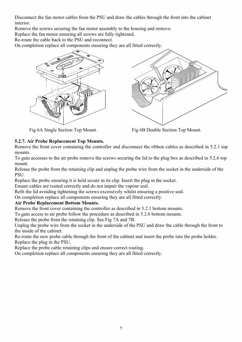
Fig 6A Single Section Top Mount. Fig 6B Double Section Top Mount.
5.2.7. Air Probe Replacement Top Mounts.Remove the front cover containing the controller and disconnect the ribbon cables as described in 5.2.1 topmounts.To gain accesses to the air probe remove the screws securing the lid to the plug box as described in 5.2.6 topmount.Release the probe from the retaining clip and unplug the probe wire from the socket in the underside of thePSU.Replace the probe ensuring it is held secure in its clip. Insert the plug in the socket.Ensure cables are routed correctly and do not impair the vapour seal.Refit the lid avoiding tightening the screws excessively whilst ensuring a positive seal.On completion replace all components ensuring they are all fitted correctly.Air Probe Replacement Bottom Mounts.Remove the front cover containing the controller as described in 5.2.1 bottom mounts.To gain access to air probe follow the procedure as described in 5.2.6 bottom mounts.Release the probe from the retaining clip. See Fig 7A and 7B.Unplug the probe wire from the socket in the underside of the PSU and draw the cable through the front tothe inside of the cabinet.Re-route the new probe cable through the front of the cabinet and insert the probe into the probe holder.Replace the plug in the PSU.Replace the probe cable retaining clips and ensure correct routing.On completion replace all components ensuring they are all fitted correctly.
6
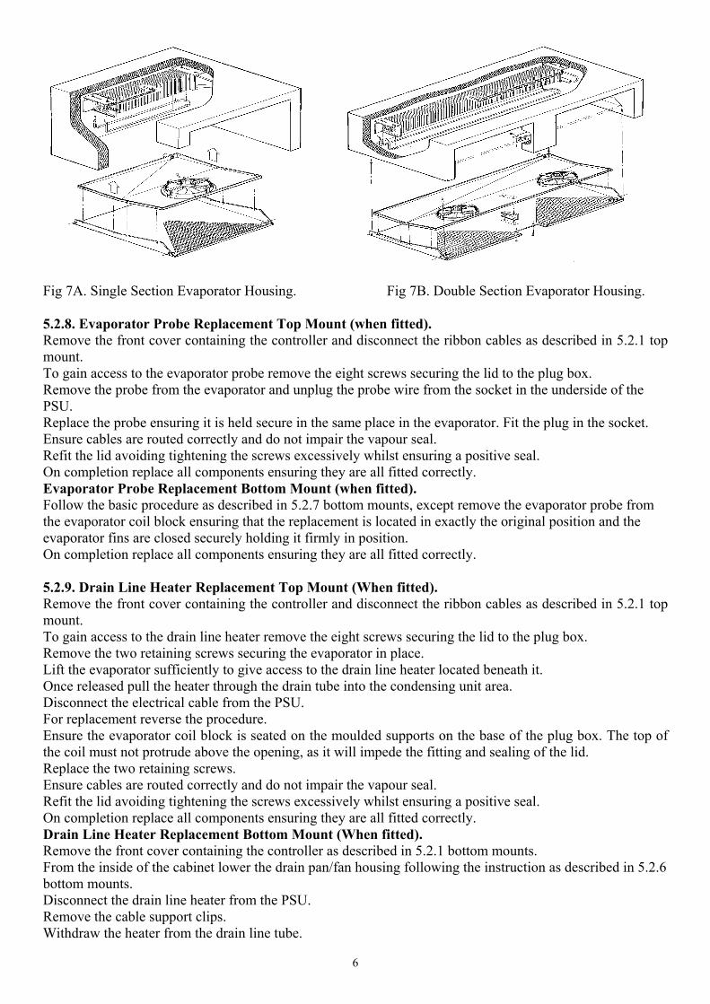
Fig 7A. Single Section Evaporator Housing. Fig 7B. Double Section Evaporator Housing.
5.2.8. Evaporator Probe Replacement Top Mount (when fitted).Remove the front cover containing the controller and disconnect the ribbon cables as described in 5.2.1 topmount.To gain access to the evaporator probe remove the eight screws securing the lid to the plug box.Remove the probe from the evaporator and unplug the probe wire from the socket in the underside of thePSU.Replace the probe ensuring it is held secure in the same place in the evaporator. Fit the plug in the socket.Ensure cables are routed correctly and do not impair the vapour seal.Refit the lid avoiding tightening the screws excessively whilst ensuring a positive seal.On completion replace all components ensuring they are all fitted correctly.Evaporator Probe Replacement Bottom Mount (when fitted).Follow the basic procedure as described in 5.2.7 bottom mounts, except remove the evaporator probe fromthe evaporator coil block ensuring that the replacement is located in exactly the original position and theevaporator fins are closed securely holding it firmly in position.On completion replace all components ensuring they are all fitted correctly.
5.2.9. Drain Line Heater Replacement Top Mount (When fitted).Remove the front cover containing the controller and disconnect the ribbon cables as described in 5.2.1 topmount.To gain access to the drain line heater remove the eight screws securing the lid to the plug box.Remove the two retaining screws securing the evaporator in place.Lift the evaporator sufficiently to give access to the drain line heater located beneath it.Once released pull the heater through the drain tube into the condensing unit area.Disconnect the electrical cable from the PSU.For replacement reverse the procedure.Ensure the evaporator coil block is seated on the moulded supports on the base of the plug box. The top ofthe coil must not protrude above the opening, as it will impede the fitting and sealing of the lid.Replace the two retaining screws.Ensure cables are routed correctly and do not impair the vapour seal.Refit the lid avoiding tightening the screws excessively whilst ensuring a positive seal.On completion replace all components ensuring they are all fitted correctly.Drain Line Heater Replacement Bottom Mount (When fitted).Remove the front cover containing the controller as described in 5.2.1 bottom mounts.From the inside of the cabinet lower the drain pan/fan housing following the instruction as described in 5.2.6bottom mounts.Disconnect the drain line heater from the PSU.Remove the cable support clips.Withdraw the heater from the drain line tube.

7
Remove the pipe cover from the rear of the cabinet. See Fig 8.
Fig 8
Unclip the drain tube from the cabinet.Draw the cable through the front of the cabinet.Remove the vertical drain tube from the elbow by pulling sharply downwards.Re-route the new drain line heater through the front of the cabinet into the drain tube ensuring that at least450mm is inside the tube.Replace the vertical drain tube, replace the retaining clips and fit the rear cover.Re-route the cable through the retaining clips ensuring it cannot come into contact with the electric defrostheater.Re-connect the cable to the PSU.On completion replace all components ensuring they are all fitted correctly.
5.2.10. Evaporator Coil Replacement Top Mount.Remove the unit cover and disconnect the ribbon cables as described in 5.2.1 top mounts.To gain accesses to the evaporator fan unscrew the eight screws securing the lid to the plug box (see fig 6A).Reclaim the refrigerant.Remove the two retaining screws securing the evaporator in place.On satisfactory reclamation of the refrigerant disconnect the pipework from the evaporator and tape the endsof the pipes to avoid moisture ingress into the system. With the pipes disconnected remove the evaporator from the locating slots in the plug box. Fit the new coil ensuring the evaporator coil block is seated on the moulded supports on the base of the plugbox. The top of the coil must not protrude above the opening, as it will impede the fitting and sealing of thelid.Replace the two retaining screws.Remove the tape from the ends of the pipes and connect the pipe work ensuring that when brazing the flamedoes not come into contact with the plastic plug box. It is good refrigeration practice to replace the drier when replacing component parts in the refrigerationsystem. Evacuate the system and charge with the correct amount of gas as shown in the technical data. Reconnect all electrical connections. Once the system has been recharged with refrigerant check for leaks. Ensure cables are routed correctly and do not impair the vapour seal.Refit the lid avoiding tightening the screws excessively whilst ensuring a positive seal.On completion replace all components ensuring they are all fitted correctly.Evaporator Coil Replacement Bottom Mount.Remove the front cover containing the controller and disconnect the ribbon cables as described in 5.2.1 topmount.Remove the shelves, trayslides and ladderack.Disconnect the evaporator fan motor cables from the PSU.
8
Remove the drain pan/fan housing fixing screws as described in 5.2.6, lower ensuring the fan motor isvisible.Draw the cables through the front of the cabinet and remove the retaining clips.Withdraw the drain line heater (if fitted) from the drain tube.Gently pull forward the housing releasing it from the retained drain tube in the back of the cabinet and fromthe rear support pins. See Fig 7A and 7B.Remove the housing from the cabinetRemove the clips securing the defrost heater (if fitted) to the evaporator and remove it. The heater can be leftin the cabinet supported by its cables taking care that it does not damage the interior of the cabinet.Reclaim the refrigerant.On satisfactory reclamation of the refrigerant disconnect the pipework from the evaporator and tape the endsof the pipes to avoid moisture ingress into the system. With the pipes disconnected remove the evaporator from the cabinet interior. Fit the replacement.Remove the tape from the ends of the pipes and connect the pipe work. It is good refrigeration practice to replace the drier when replacing component parts in the refrigerationsystem.Evacuate the system and charge with the correct amount of gas as shown in the technical data. Once the system has been recharged with refrigerant check for leaks.Replace the defrost heater (if fitted).Replace the drain pan/fan housing ensuring the drain tube is inserted into the drain line tube and supportpins.Replace the drain line heater following instructions as described in 5.2.9.Re-route the evaporator fan motor cables through the front into the PSU and re-connect.On completion replace all components ensuring they are all fitted correctly.
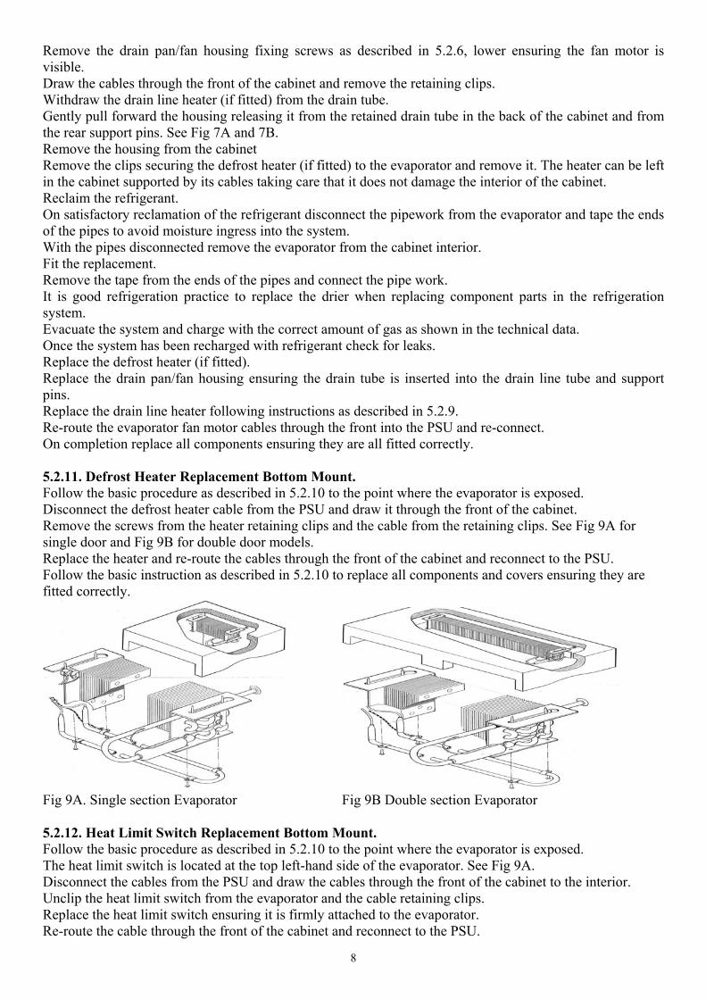
5.2.11. Defrost Heater Replacement Bottom Mount.Follow the basic procedure as described in 5.2.10 to the point where the evaporator is exposed.Disconnect the defrost heater cable from the PSU and draw it through the front of the cabinet.Remove the screws from the heater retaining clips and the cable from the retaining clips. See Fig 9A forsingle door and Fig 9B for double door models.Replace the heater and re-route the cables through the front of the cabinet and reconnect to the PSU. Follow the basic instruction as described in 5.2.10 to replace all components and covers ensuring they arefitted correctly.
Fig 9A. Single section Evaporator Fig 9B Double section Evaporator
5.2.12. Heat Limit Switch Replacement Bottom Mount.Follow the basic procedure as described in 5.2.10 to the point where the evaporator is exposed.The heat limit switch is located at the top left-hand side of the evaporator. See Fig 9A.Disconnect the cables from the PSU and draw the cables through the front of the cabinet to the interior.Unclip the heat limit switch from the evaporator and the cable retaining clips.Replace the heat limit switch ensuring it is firmly attached to the evaporator.Re-route the cable through the front of the cabinet and reconnect to the PSU.

9
On completion replace all components and covers ensuring they are fitted correctly.
5.2.13 Dual Temperature Single Section Top Mount Models.For basic information on changing Evaporator Fan motor see 5.2.6.Air Probes see 5.2.7.Evaporator Probe see 5.2.8.Drain Line Heater see 5.2.9.Evaporator Coils see 5.2.10.Defrost Heater see 5.2.11.Heat Limit Switch see 5.2.12.For cabinet general arrangement see Fig 10.
Fig 10 Dual Temperature Single Section Top Mount Models.
5.2.14. Door /Hinge Cartridge Replacement All Models.Remove the large hexagon nut from the hinge cartridge (normally fitted at the bottom of the door). See Fig11.Remove the front cover containing the controller and disconnect the ribbon cables as described in 5.2.1.Remove the bottom unit cover.Remove the pivot pin (normally located at the top of the door).With the door in the closed position slide the door out of the pivot bush and the top bracket.Open the door to 45° angle to the cabinet and lift it away from the bottom hinge.Rest the edge of the door on the floor, handle side downwards ensuring the edge is protected drill out therivets securing the cartridge to the door and remove it.Fit the replacement cartridge using 3/16” pop rivets.

10
Fit the door to the bottom bracket with the door in the open position at a 90° angle to the cabinet.Close the door and locate the pivot bush into the top hinge, once located fit the pivot pin and tighten fully.Check the door for correct closure.In the event of the door not closing properly or springing open would indicate that the incorrect hingecartridge has been fitted.Remove the door and hinge cartridge as previous and fit the correct hinge cartridge.Check door locks correctly.
Fig 11. Standard Hinge Parts.
5.1.15. Door Lock Replacement.Open the door.Remove the two fixing screws securing the lock to the door at the rear of the door handle.

11
Extract the lock from the door.Fit the replacement lock and secure using the two screws.Close the door and check alignment with the door keep.5.1.16. Door Frame Surround Heater Replacement.Open the door to expose the black plastic door frame surround. See fig 12.
. Fig 12
Firstly remove the cover strip on the sides using a pallet knife. See Fig 13.
Fig 13
Completely remove the side strips and then proceed to remove the top and bottom cover strips.Insert a 4mm Allen key behind the cover strip in the corner (see Fig 14) and prise it off.
12
Fig 14A. Standard Opening. Fig 14B. Bottom Mount and Half Door Option.
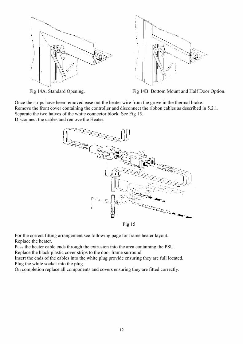
Once the strips have been removed ease out the heater wire from the grove in the thermal brake. Remove the front cover containing the controller and disconnect the ribbon cables as described in 5.2.1.Separate the two halves of the white connector block. See Fig 15.Disconnect the cables and remove the Heater.
Fig 15 For the correct fitting arrangement see following page for frame heater layout.Replace the heater.Pass the heater cable ends through the extrusion into the area containing the PSU.Replace the black plastic cover strips to the door frame surround.Insert the ends of the cables into the white plug provide ensuring they are full located.Plug the white socket into the plug.On completion replace all components and covers ensuring they are fitted correctly.

13
Frame Heater Layouts for Model Options.