parts manual port a scrub 14 with power...
TRANSCRIPT
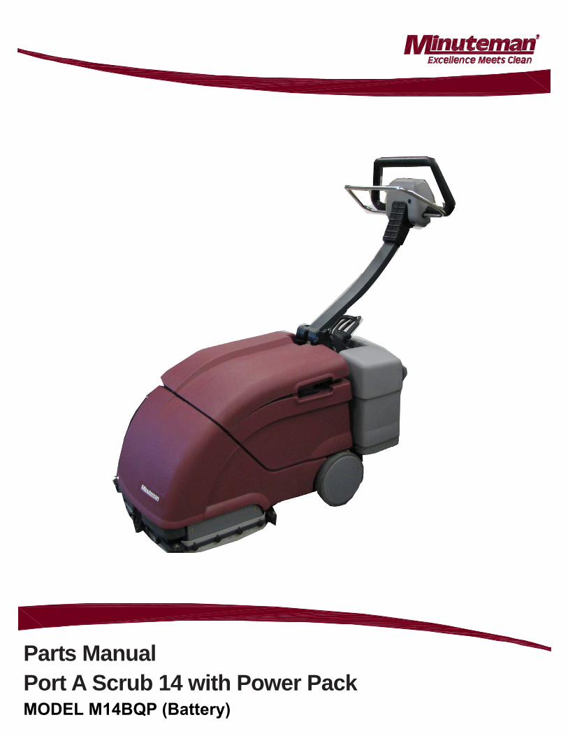
Parts ManualPort A Scrub 14 with Power Pack MODEL M14BQP (Battery)
Parts Manual - Port A Scrub 14 with Power Pack
Introduction
PrefacePlease be advised explicitly that wecannot accept any legal issues out of thecontents of this manual. If repair work hasto be performed make sure that onlygenuine spare parts are used; onlygenuine spare parts may guarantee adependable machine. We reserve theright for technical improvement..
Valid as of: 05/09
Minuteman International Inc.14N845 US ROUTE 20PINGREE GROVE, IL. 60140-8893U.S.A
Proper useThe machine is a vacuum scrubbingmachine for wet cleaning of hard-surfaced floors. Using the machinebeyond this scope of application will bedeemed improper use; The manufacturercannot be held liable for consequentialdamages; the user alone bears the risk.The term of proper use also includesoperation, maintenance and repair workto be performed in compliance with themanufacturer’s specifications. The E 24may only be used by persons that arefamiliar with the machine and aware ofpossible hazards involved. Ifmodifications to the machine are madein absence of the manufacturer’s priorconsent, the latter cannot be held liablefor damage resulting from suchunauthorized modification.
Notes on warrantyThe terms of the sales contract apply.Damages are not subject to warranty ifthey are due to non-compliance with themaintenance and service provisions. Themaintenance work has to be performedby an authorized Minuteman servicecenter.The following is excluded from warranty:fuses, natural wear, damages caused byoverload, inexpert handling andunauthorized modification of themachine. Moreover, any claim forwarranty cannot be accepted if damagesof the machine are caused by fitting partsor accessories without Minuteman’s priorand explicit consent or by non-compliance with the maintenanceinstructions.
Page 3Parts Manual - Port A Scrub 14 with Power Pack
• Stop on level surface.
• Disconnect the power to the machine by pulling the red Battery Connector located under the recovery tanknear the batteries.
• Avoid moving parts. Do not wear loose jackets, shirts, or sleeves when working on machine.
• Avoid contact with battery acid. Battery acid can cause burns. When working on or around batteries, wearprotective clothing and safety glasses. Remove metal jewelry. Do not lay tools or metal objects on top ofbatteries.
• Do not clean machine with a pressure washer.
• Authorized personnel must perform repairs and maintenance. Use Minuteman supplied replacement parts.
For Safety When Servicing or Maintaining Machine
Parts Manual - Port A Scrub 14 with Power Pack
TABLE OF CONTENTS
FOR SAFETY WHEN SERVICING OR MAINTAINING MACHINE ............................................................ 3CHASSIS ASSEMBLY .................................................................................................................. 5HANDLE ASSEMBLY ................................................................................................................... 6BRUSH CONTROL ASSEMBLY ....................................................................................................... 8BRUSH HEAD ASSEMBLY .......................................................................................................... 10VACUUM MOTOR ASSEMBLY 1 ................................................................................................... 12VACUUM MOTOR ASSEMBLY 2 ................................................................................................... 13SQUEEGEE ASSEMBLY ............................................................................................................. 14SQUEEGEE LIFTING ASSEMBLY .................................................................................................. 16WATER FEED ASSEMBLY........................................................................................................... 18TANK ASSEMBLY .................................................................................................................... 19BRUSH HEAD MOUNTING ASSEMBLY............................................................................................ 21ELECTRIC ASSEMBLY 1............................................................................................................ 22ELECTRIC ASSEMBLY 2............................................................................................................ 23COVERING ASSEMBLY .............................................................................................................. 24POWER TROLLEY ASSEMBLY ..................................................................................................... 25LABELING ............................................................................................................................. 27WARRANTY............................................................................................................................ 28
Page 5Parts Manual - Port A Scrub 14 with Power Pack
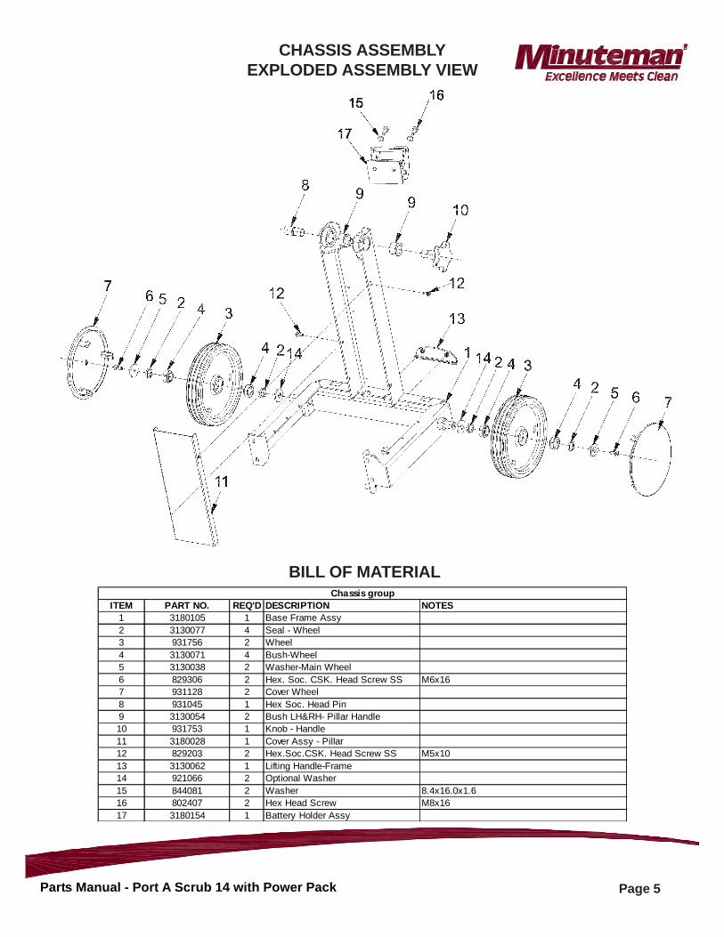
ITEM PART NO. REQ'D DESCRIPTION NOTES1 3180105 1 Base Frame Assy2 3130077 4 Seal - Wheel3 931756 2 Wheel4 3130071 4 Bush-Wheel5 3130038 2 Washer-Main Wheel6 829306 2 Hex. Soc. CSK. Head Screw SS M6x167 931128 2 Cover Wheel8 931045 1 Hex Soc. Head Pin9 3130054 2 Bush LH&RH- Pillar Handle10 931753 1 Knob - Handle11 3180028 1 Cover Assy - Pillar12 829203 2 Hex.Soc.CSK. Head Screw SS M5x1013 3130062 1 Lifting Handle-Frame14 921066 2 Optional Washer15 844081 2 Washer 8.4x16.0x1.616 802407 2 Hex Head Screw M8x1617 3180154 1 Battery Holder Assy
Chassis group
BILL OF MATERIAL
CHASSIS ASSEMBLYEXPLODED ASSEMBLY VIEW
Page 6Parts Manual - Port A Scrub 14 with Power Pack
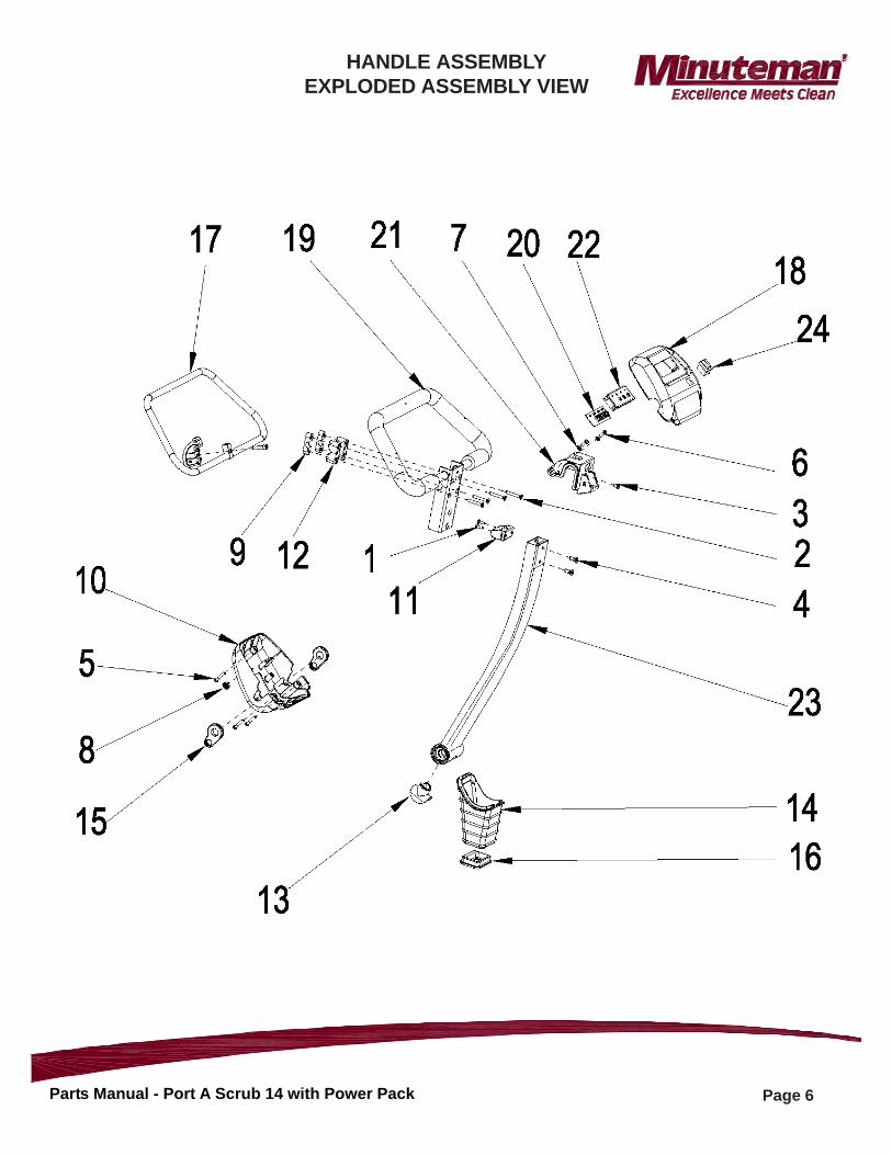
HANDLE ASSEMBLYEXPLODED ASSEMBLY VIEW
Page 7Parts Manual - Port A Scrub 14 with Power Pack
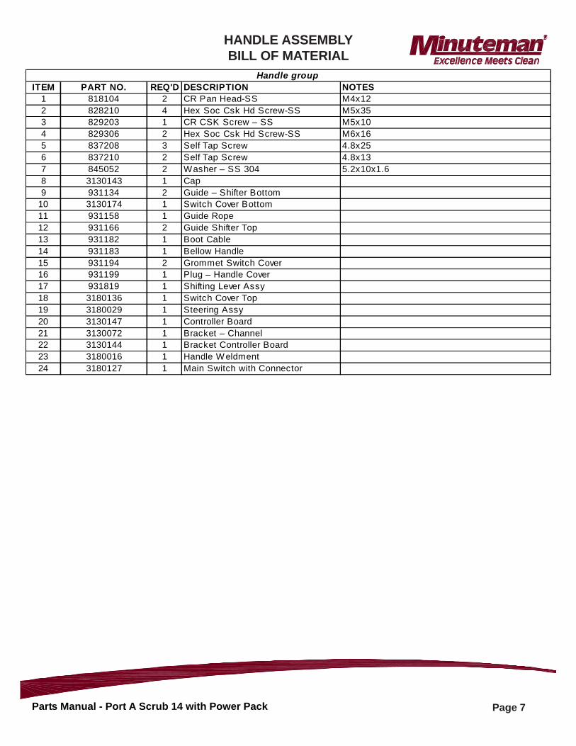
ITEM PART NO. REQ'D DESCRIPTION NOTES1 818104 2 CR Pan Head-SS M4x122 828210 4 Hex Soc Csk Hd Screw-SS M5x353 829203 1 CR CSK Screw – SS M5x104 829306 2 Hex Soc Csk Hd Screw-SS M6x165 837208 3 Self Tap Screw 4.8x256 837210 2 Self Tap Screw 4.8x137 845052 2 Washer – SS 304 5.2x10x1.68 3130143 1 Cap9 931134 2 Guide – Shifter Bottom
10 3130174 1 Switch Cover Bottom 11 931158 1 Guide Rope12 931166 2 Guide Shifter Top13 931182 1 Boot Cable14 931183 1 Bellow Handle15 931194 2 Grommet Switch Cover16 931199 1 Plug – Handle Cover17 931819 1 Shifting Lever Assy18 3180136 1 Switch Cover Top 19 3180029 1 Steering Assy20 3130147 1 Controller Board21 3130072 1 Bracket – Channel22 3130144 1 Bracket Controller Board 23 3180016 1 Handle W eldment24 3180127 1 Main Switch with Connector
Handle group
HANDLE ASSEMBLYBILL OF MATERIAL
Page 8Parts Manual - Port A Scrub 14 with Power Pack
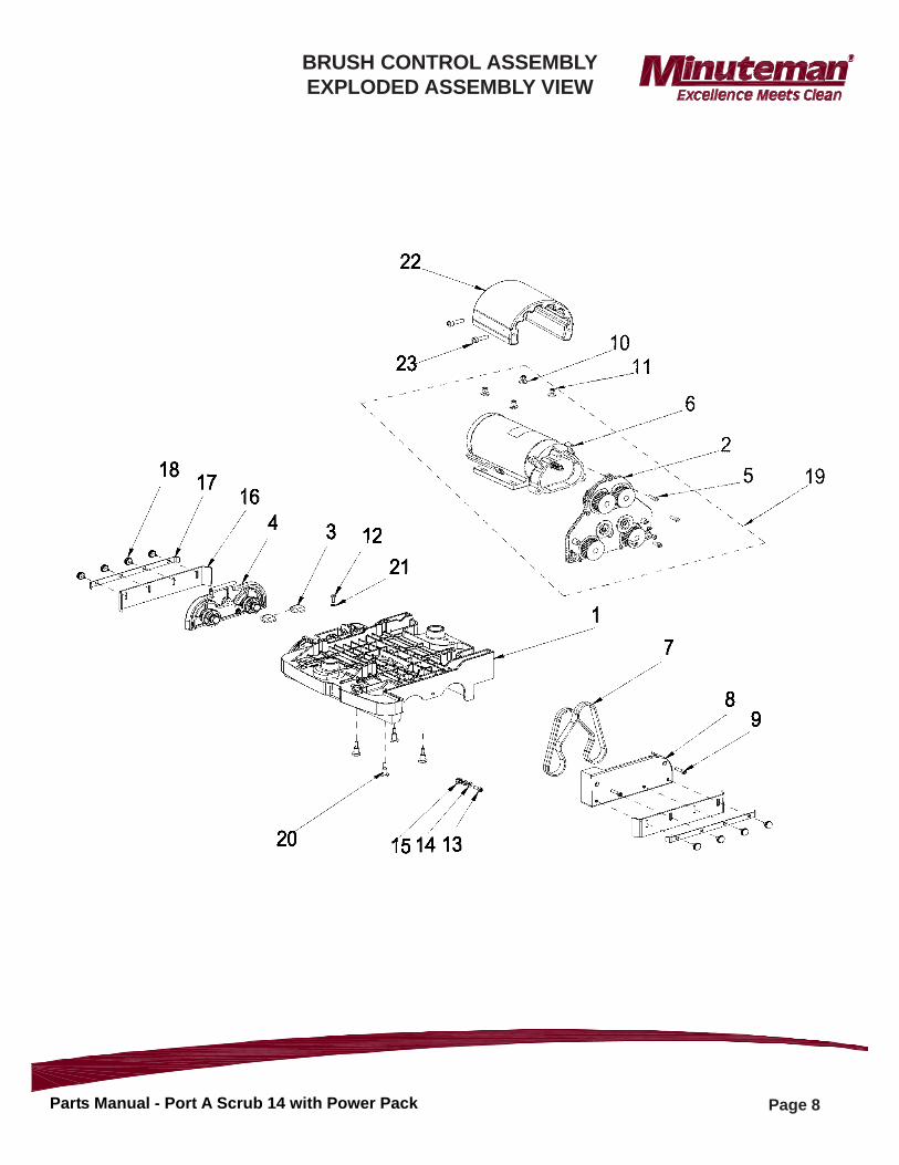
BRUSH CONTROL ASSEMBLYEXPLODED ASSEMBLY VIEW
Page 9Parts Manual - Port A Scrub 14 with Power Pack
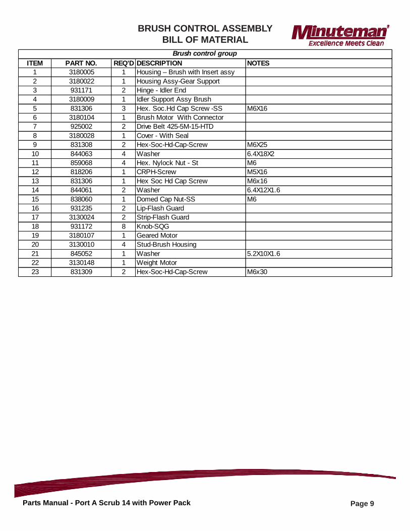
ITEM PART NO. REQ'D DESCRIPTION NOTES1 3180005 1 Housing – Brush with Insert assy2 3180022 1 Housing Assy-Gear Support3 931171 2 Hinge - Idler End4 3180009 1 Idler Support Assy Brush5 831306 3 Hex. Soc.Hd Cap Screw -SS M6X166 3180104 1 Brush Motor With Connector7 925002 2 Drive Belt 425-5M-15-HTD8 3180028 1 Cover - With Seal9 831308 2 Hex-Soc-Hd-Cap-Screw M6X2510 844063 4 Washer 6.4X18X211 859068 4 Hex. Nylock Nut - St M612 818206 1 CRPH-Screw M5X1613 831306 1 Hex Soc Hd Cap Screw M6x1614 844061 2 Washer 6.4X12X1.615 838060 1 Domed Cap Nut-SS M616 931235 2 Lip-Flash Guard17 3130024 2 Strip-Flash Guard18 931172 8 Knob-SQG19 3180107 1 Geared Motor20 3130010 4 Stud-Brush Housing21 845052 1 Washer 5.2X10X1.622 3130148 1 Weight Motor23 831309 2 Hex-Soc-Hd-Cap-Screw M6x30
Brush control group
BRUSH CONTROL ASSEMBLYBILL OF MATERIAL
Page 10Parts Manual - Port A Scrub 14 with Power Pack
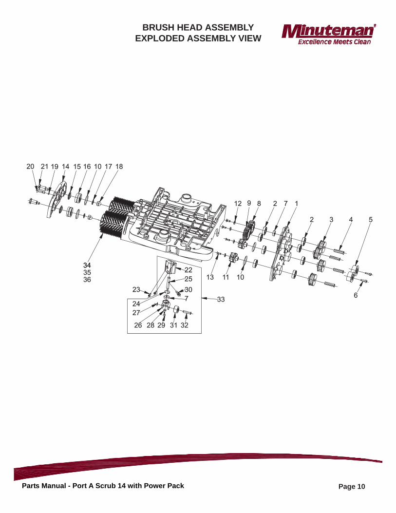
BRUSH HEAD ASSEMBLYEXPLODED ASSEMBLY VIEW
20 1921 14 15 16 10 17 18
12 9 8 2 7 1
2 3 4 5
6
13 11 10
33
22
25
30
7
23
24
27
26 28 29 31 32
34343536
Page 11Parts Manual - Port A Scrub 14 with Power Pack
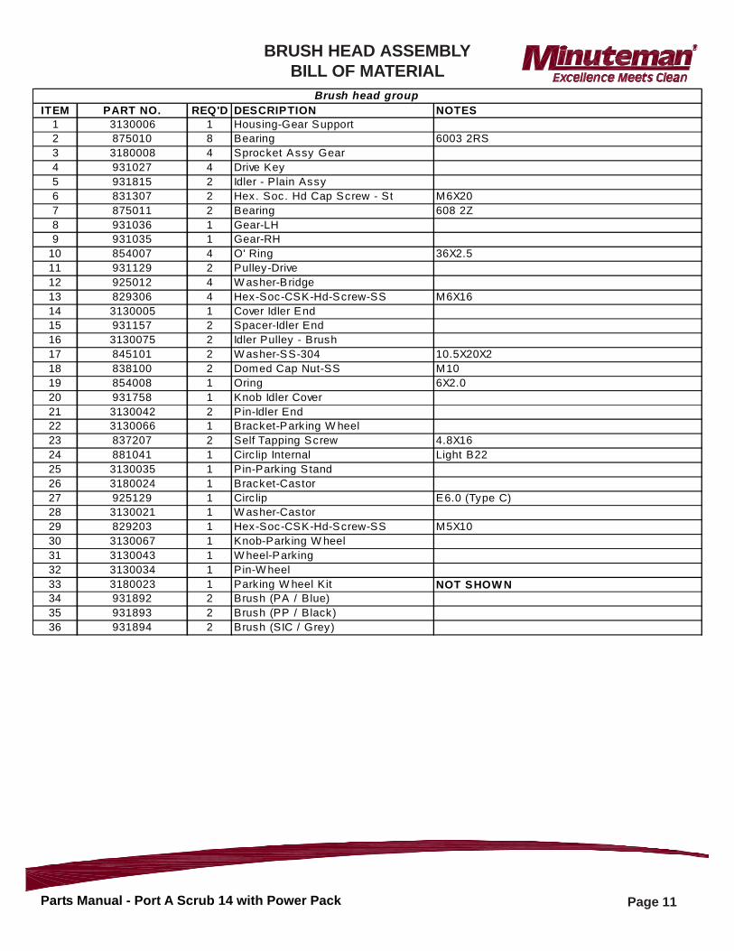
ITEM PART NO. REQ'D DESCRIPTION NOTES1 3130006 1 Housing-Gear Support2 875010 8 Bearing 6003 2RS3 3180008 4 Sprocket Assy Gear4 931027 4 Drive Key5 931815 2 Idler - Plain Assy6 831307 2 Hex. Soc. Hd Cap Screw - St M6X207 875011 2 Bearing 608 2Z8 931036 1 Gear-LH9 931035 1 Gear-RH
10 854007 4 O' Ring 36X2.511 931129 2 Pulley-Drive12 925012 4 W asher-Bridge13 829306 4 Hex-Soc-CSK-Hd-Screw-SS M6X1614 3130005 1 Cover Idler End15 931157 2 Spacer-Idler End16 3130075 2 Idler Pulley - Brush17 845101 2 W asher-SS-304 10.5X20X218 838100 2 Domed Cap Nut-SS M1019 854008 1 Oring 6X2.020 931758 1 Knob Idler Cover21 3130042 2 Pin-Idler End22 3130066 1 Bracket-Park ing W heel23 837207 2 Self Tapping Screw 4.8X1624 881041 1 Circ lip Internal Light B2225 3130035 1 Pin-Parking Stand26 3180024 1 Bracket-Castor27 925129 1 Circ lip E6.0 (Type C)28 3130021 1 W asher-Castor29 829203 1 Hex-Soc-CSK-Hd-Screw-SS M5X1030 3130067 1 Knob-Parking W heel31 3130043 1 W heel-Parking32 3130034 1 Pin-W heel33 3180023 1 Parking W heel Kit NOT SHOW N34 931892 2 Brush (PA / Blue)35 931893 2 Brush (PP / Black)36 931894 2 Brush (SIC / Grey)
Brush head group
BRUSH HEAD ASSEMBLYBILL OF MATERIAL
Page 12Parts Manual - Port A Scrub 14 with Power Pack
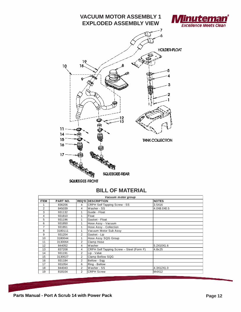
ITEM PART NO. REQ'D DESCRIPTION NOTES1 836206 4 CRPH Self Tapping Screw - SS 3.5X162 845039 4 Washer - SS 4.0X8.0X0.53 931132 1 Guide - Float4 931810 1 Float5 931196 1 Gasket - Float6 931850 1 Hose Assy - Vacuum7 931851 1 Hose Assy - Collection8 3180111 1 Vacuum Motor Sub Assy9 931204 2 Gasket - Lip10 3180044 1 Hose Assy SQG Group11 3130064 2 Clamp Hose12 844052 4 Washer 5.2X10X1.613 837208 4 CRPH Self Tapping Screw – Steel (Form F) 4.8x2514 931191 2 Lip - Valve15 3130027 2 Clamp Bellow SQG16 931184 2 Bellow - Sqg17 931054 6 Ring - Bellow18 844043 2 Washer - SS 4.3X12X1.019 818104 2 CRPH Screw M4X12
Vacuum motor group
BILL OF MATERIAL
VACUUM MOTOR ASSEMBLY 1EXPLODED ASSEMBLY VIEW
Page 13Parts Manual - Port A Scrub 14 with Power Pack
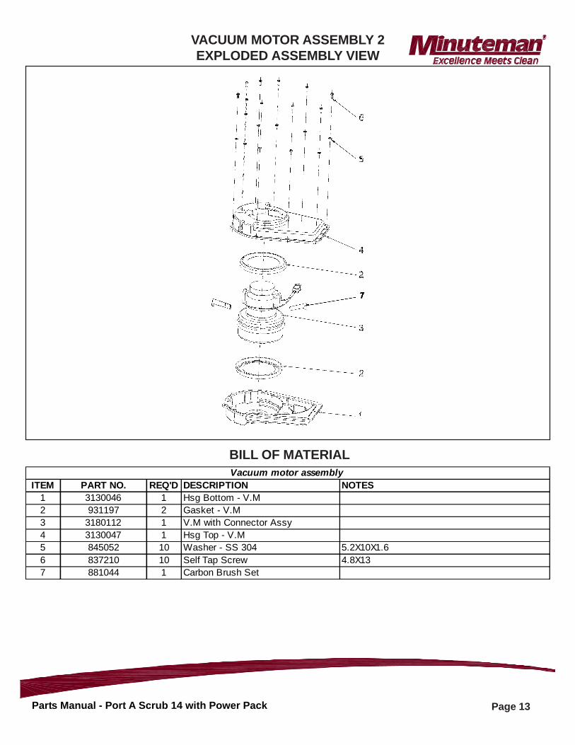
ITEM PART NO. REQ'D DESCRIPTION NOTES1 3130046 1 Hsg Bottom - V.M2 931197 2 Gasket - V.M3 3180112 1 V.M with Connector Assy4 3130047 1 Hsg Top - V.M5 845052 10 Washer - SS 304 5.2X10X1.66 837210 10 Self Tap Screw 4.8X137 881044 1 Carbon Brush Set
Vacuum motor assembly
BILL OF MATERIAL
VACUUM MOTOR ASSEMBLY 2EXPLODED ASSEMBLY VIEW
Page 14Parts Manual - Port A Scrub 14 with Power Pack
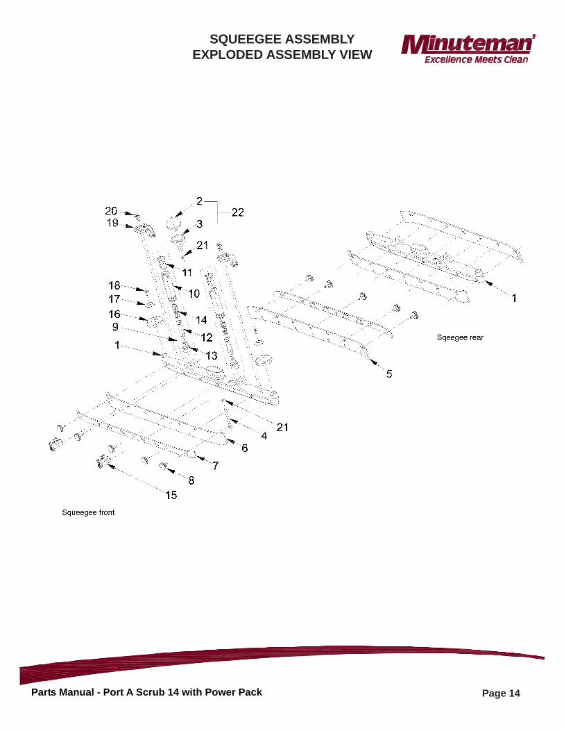
SQUEEGEE ASSEMBLYEXPLODED ASSEMBLY VIEW
Page 15Parts Manual - Port A Scrub 14 with Power Pack
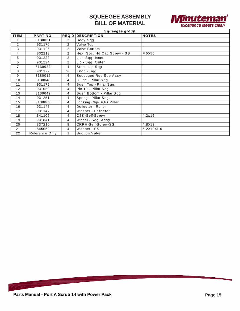
ITEM PART NO. REQ'D DESCRIP TION NOTES1 3130051 2 Body Sqg2 931170 2 Valve Top3 931126 2 Valve Bottom4 832213 2 Hex . Soc . Hd Cap S c rew - SS M 5X505 931233 2 Lip - S qg. Inner6 931224 2 Lip - S qg. Outer7 3130022 4 S trip - Lip S qg8 931172 20 Knob - Sqg9 3180012 4 Squeegee Rod Sub A ssy10 3130048 4 Guide - P illar S qg11 931175 4 Bush Top - P illar Sqg.12 931050 4 P in 10 - P illar S qg13 3130049 4 Bush Bottom - P illar S qg14 931251 4 Spring - P illar S qg.15 3130063 4 Lock ing Clip-S QG P illar16 931146 4 Deflec tor - Roller17 931147 4 W asher - Deflec tor18 841106 4 CSK -Self-Sc rew 4.2x1619 931841 4 W heel - S qg. Assy20 837210 8 CRP H-Self-Sc rew-SS 4.8X1321 845052 4 W asher - SS 5.2X10X1.622 Reference Only 1 Suc tion V alve
S queegee g roup
SQUEEGEE ASSEMBLYBILL OF MATERIAL
Page 16Parts Manual - Port A Scrub 14 with Power Pack
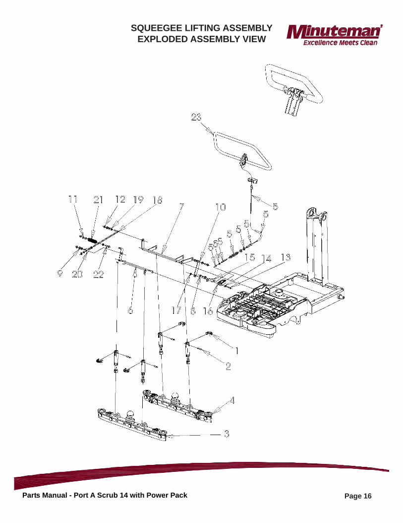
SQUEEGEE LIFTING ASSEMBLYEXPLODED ASSEMBLY VIEW
Page 17Parts Manual - Port A Scrub 14 with Power Pack
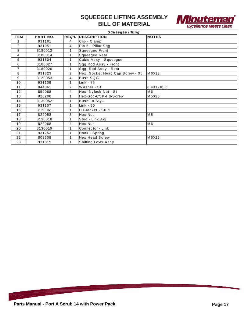
ITEM P ART NO. REQ 'D DES CRIP TION NOTES1 931181 4 Clip - Clam p2 931051 4 P in 6 - P illar S qg3 3180013 1 S queegee Front4 3180014 1 S queegee Rear5 931804 1 Cable A s sy - S queegee6 3180027 1 S qg Rod A s s y - Front7 3180026 1 S qg. Rod A s s y - Rear8 831323 2 Hex . S oc k et Head Cap S c rew - S t M 6X189 3130053 4 B us h-S Q G10 931109 1 Link - 7511 844061 7 W as her - S t 6.4X12X1.612 859068 4 Hex . Ny lock Nut - S t M 613 828208 1 Hex -S oc -CS K -Hd-S crew M 5X2514 3130052 1 B us h9.8-S QG15 931107 1 Link - 5016 3130061 1 U B rac k et - S tud17 822058 3 Hex -Nut M 518 3130018 1 S tud - Link A dj19 822068 4 Hex -Nut M 620 3130019 1 Connec tor - Link21 931252 1 Hook - S pring22 803308 1 Hex Head S c rew M 6X2523 931819 1 S hift ing Lever A s s y
S queegee l ifting
SQUEEGEE LIFTING ASSEMBLYBILL OF MATERIAL
Page 18Parts Manual - Port A Scrub 14 with Power Pack
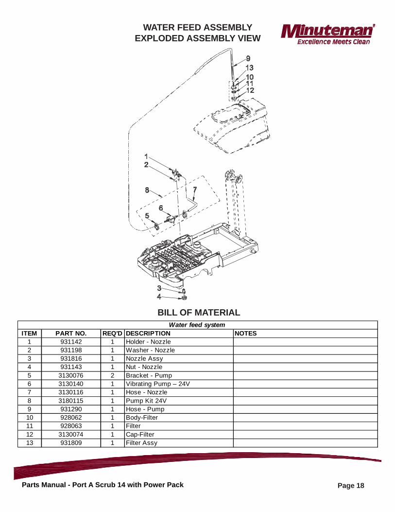
ITEM PART NO. REQ'D DESCRIPTION NOTES1 931142 1 Holder - Nozzle2 931198 1 Washer - Nozzle3 931816 1 Nozzle Assy4 931143 1 Nut - Nozzle5 3130076 2 Bracket - Pump6 3130140 1 Vibrating Pump – 24V7 3130116 1 Hose - Nozzle8 3180115 1 Pump Kit 24V 9 931290 1 Hose - Pump10 928062 1 Body-Filter11 928063 1 Filter12 3130074 1 Cap-Filter13 931809 1 Filter Assy
Water feed system
BILL OF MATERIAL
WATER FEED ASSEMBLYEXPLODED ASSEMBLY VIEW
Page 19Parts Manual - Port A Scrub 14 with Power Pack
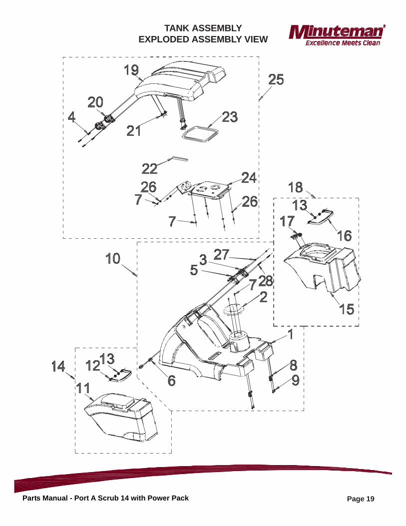
TANK ASSEMBLYEXPLODED ASSEMBLY VIEW
Page 20Parts Manual - Port A Scrub 14 with Power Pack
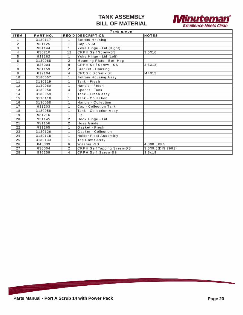
IT EM P A R T N O . R EQ 'D D ES C R IP T IO N N O T E S1 3130117 1 B o t tom H ous ing2 931125 1 C ap - V .M3 931144 1 Y ok e H inge - L id (R igh t )4 836210 12 C R P H S e lf S c rew -S S 3 .5X165 931162 1 Y ok e H inge - L id (Le ft )6 3130068 2 M oun t ing P la te - B o t . H s g7 836004 8 C R P H S e lf S c rew - S S 3 .5X138 931159 2 B rac k et - H ous ing9 812104 4 C R C S K S c rew - S t M 4X1210 3180057 1 B o t tom H ous ing A s s y11 3130119 1 Tank - F res h12 3130060 1 H andle - F res h13 3130050 4 S pac e r - Tank14 3180059 1 Tank - F res h as s y15 3130118 1 Tank - C o llec t ion16 3130058 1 H andle - C ollec t ion17 931203 1 C ap - C o llec t ion Tank18 3180058 1 Tank - C o llec t ion A s s y19 931216 1 Lid20 931145 2 H ook H inge - L id21 931156 2 H os e G u ide22 931265 1 G as k e t - F res h23 3130126 1 G as k e t - C o llec t ion24 3180118 1 H o lde r F loa t A s s em b ly25 3180133 1 Top C ove r A s s y26 845039 6 W as her -S S 4 .0X8 .0X0 .527 836004 2 C R P H S e lf Tapping S c rew -S S 3 .5X9 .5 (D IN 7981)28 836209 4 C R P H S e lf S c rew -S S 3 .5x 18
T an k g ro u p
TANK ASSEMBLYBILL OF MATERIAL
Page 21Parts Manual - Port A Scrub 14 with Power Pack
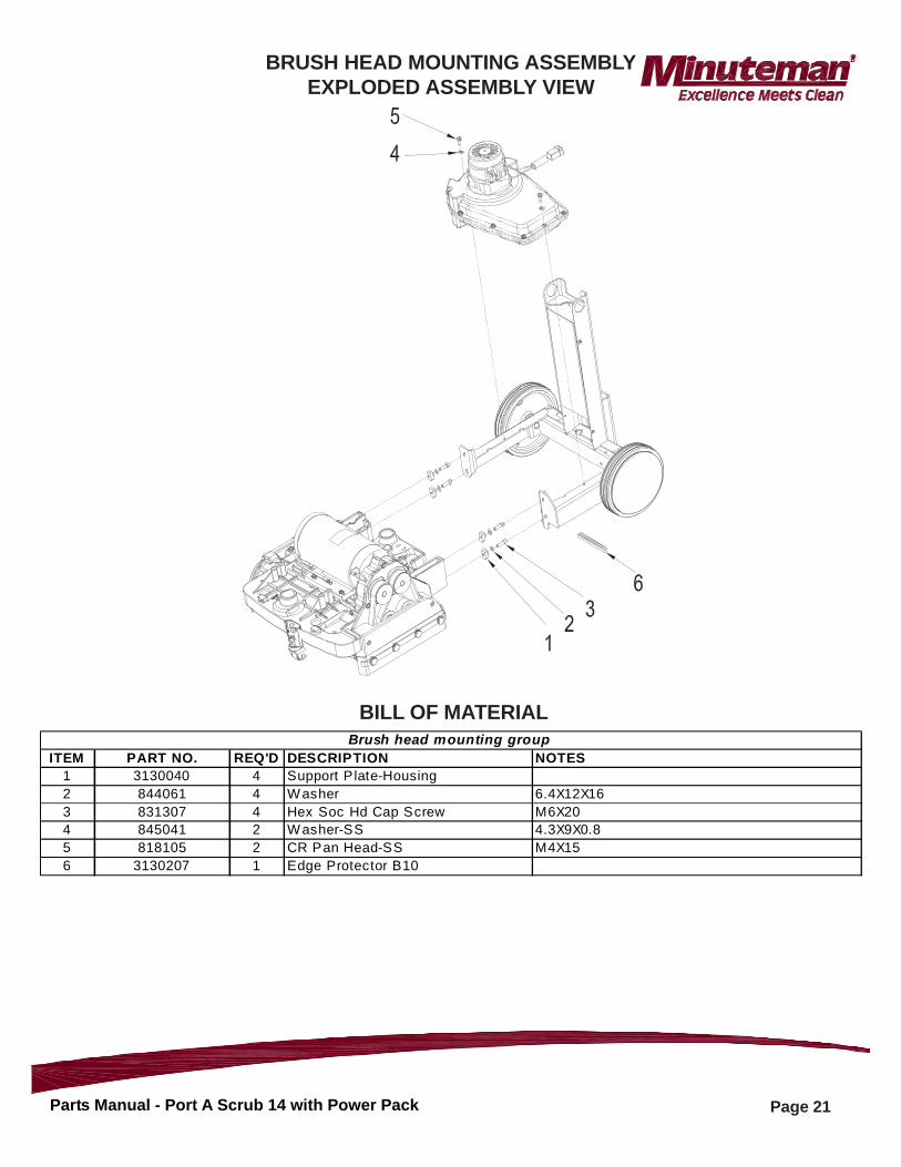
ITEM PART NO. REQ'D DESCRIPTION NOTES1 3130040 4 Support Plate-Housing2 844061 4 Washer 6.4X12X163 831307 4 Hex Soc Hd Cap Screw M6X204 845041 2 Washer-SS 4.3X9X0.85 818105 2 CR Pan Head-SS M4X156 3130207 1 Edge Protector B10
Brush head mounting group
BILL OF MATERIAL
BRUSH HEAD MOUNTING ASSEMBLYEXPLODED ASSEMBLY VIEW
Page 22Parts Manual - Port A Scrub 14 with Power Pack
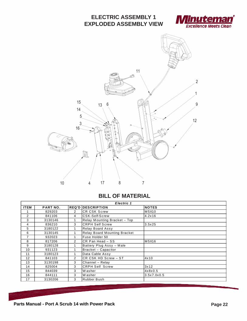
ITEM P ART NO. REQ'D DES CRIP TION NOTES1 829203 2 CR CSK S c rew M 5X10² 841106 4 CS K -Self-S c rew 4.2x163 3130146 1 Relay M ounting B racket – Top4 836210 3 CRP H S elf S crew 3.5x255 3180122 1 Relay B oard Assy6 3130145 1 Relay B oard Mounting B racket7 932023 1 Fuse Holder 508 817206 2 CR P an Head – S S M 5X169 3180128 1 B attery P lug Assy – M ale10 931123 1 B racket – Capac itor11 3180123 1 Data Cable Assy12 841103 2 CR CSK HD Sc rew – S T 4x10¹³ 3130198 3 Channel – Relay14 825004 3 CRP H S elf Sc rew 3x1215 844039 3 W asher 4x8x0.516 844111 3 W asher 3.5x7.0x0.517 3130206 3 Rubber B ush
E lectric 1
BILL OF MATERIAL
ELECTRIC ASSEMBLY 1EXPLODED ASSEMBLY VIEW
Page 23Parts Manual - Port A Scrub 14 with Power Pack
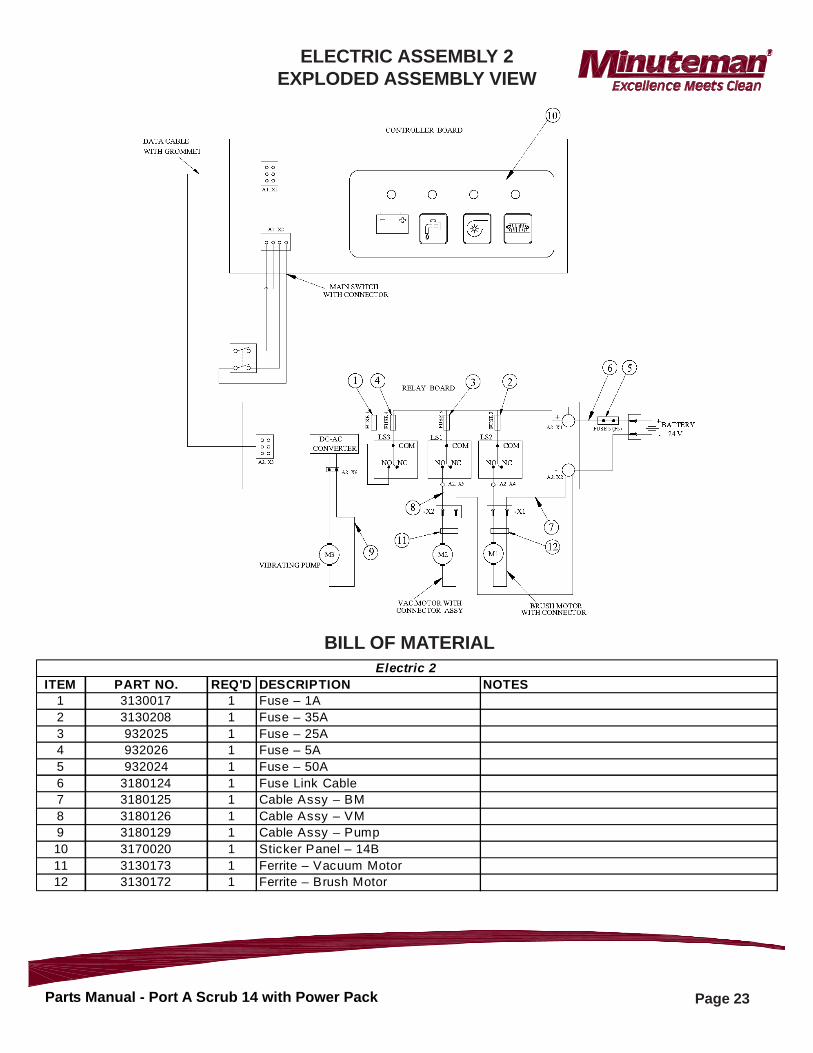
ITEM PART NO. REQ'D DESCRIPTION NOTES1 3130017 1 Fuse – 1A2 3130208 1 Fuse – 35A3 932025 1 Fuse – 25A4 932026 1 Fuse – 5A5 932024 1 Fuse – 50A6 3180124 1 Fuse Link Cable7 3180125 1 Cable Assy – BM8 3180126 1 Cable Assy – VM 9 3180129 1 Cable Assy – Pump 10 3170020 1 Sticker Panel – 14B11 3130173 1 Ferrite – Vacuum Motor12 3130172 1 Ferrite – Brush Motor
Electric 2
BILL OF MATERIAL
ELECTRIC ASSEMBLY 2EXPLODED ASSEMBLY VIEW
Page 24Parts Manual - Port A Scrub 14 with Power Pack
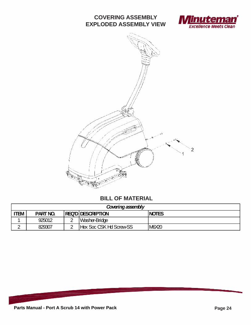
ITEM PART NO. REQ'D DESCRIPTION NOTES1 925012 2 Washer-Bridge2 829307 2 Hex Soc CSK Hd Screw-SS M6X20
Covering assembly BILL OF MATERIAL
COVERING ASSEMBLYEXPLODED ASSEMBLY VIEW
Page 25Parts Manual - Port A Scrub 14 with Power Pack
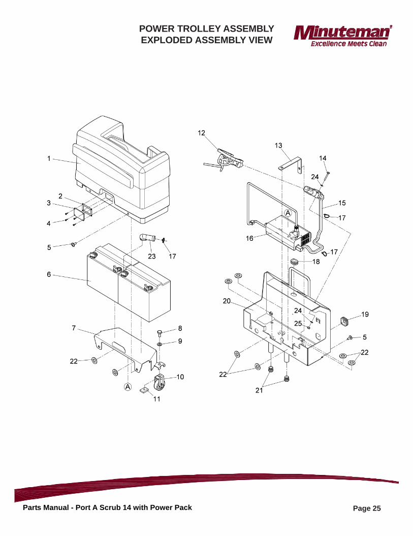
POWER TROLLEY ASSEMBLYEXPLODED ASSEMBLY VIEW
Page 26Parts Manual - Port A Scrub 14 with Power Pack
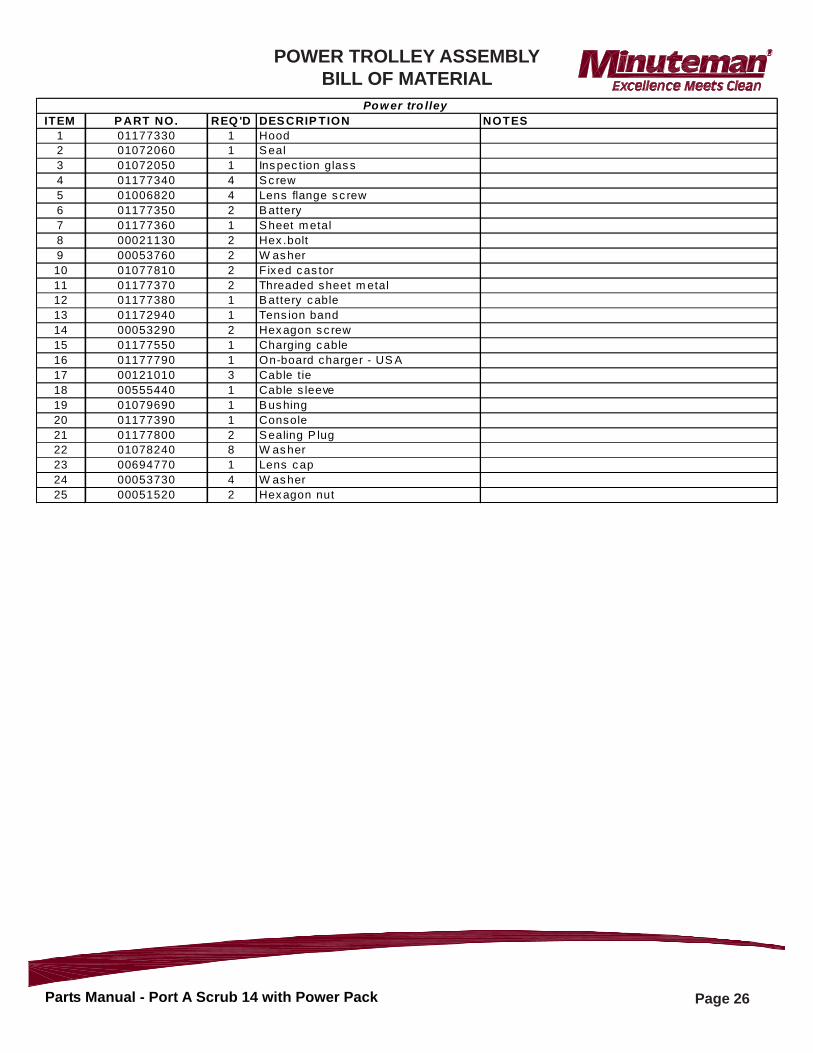
ITEM P ART NO. REQ 'D DES CRIP TION NOTES1 01177330 1 Hood2 01072060 1 S eal3 01072050 1 Ins pec tion glas s4 01177340 4 S c rew5 01006820 4 Lens flange s c rew6 01177350 2 B attery7 01177360 1 S heet m etal8 00021130 2 Hex .bolt9 00053760 2 W as her10 01077810 2 Fix ed c as tor11 01177370 2 Threaded sheet m etal12 01177380 1 B attery c able13 01172940 1 Tens ion band14 00053290 2 Hex agon s c rew15 01177550 1 Charging c able16 01177790 1 On-board charger - US A17 00121010 3 Cable t ie18 00555440 1 Cable s leeve19 01079690 1 B us hing20 01177390 1 Console21 01177800 2 S ealing P lug22 01078240 8 W as her23 00694770 1 Lens c ap24 00053730 4 W as her25 00051520 2 Hex agon nut
Pow er tro lley
POWER TROLLEY ASSEMBLYBILL OF MATERIAL
Page 27Parts Manual - Port A Scrub 14 with Power Pack
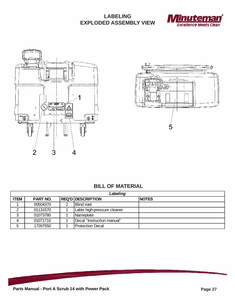
ITEM PART NO. REQ'D DESCRIPTION NOTES1 00504370 2 Blind rivet2 01131570 1 Lable high-pressure cleaner3 01073780 1 Nameplate4 01071710 1 Decal "Instruction manual"5 17267550 1 Protection Decal
Labeling BILL OF MATERIAL
LABELINGEXPLODED ASSEMBLY VIEW
14N845 U.S. Route 20 Pingree grove, IL 60140 Phone: 800-237-3192
E-Mail: www.minu temanin tl.com 988733B
Rev A 07/16
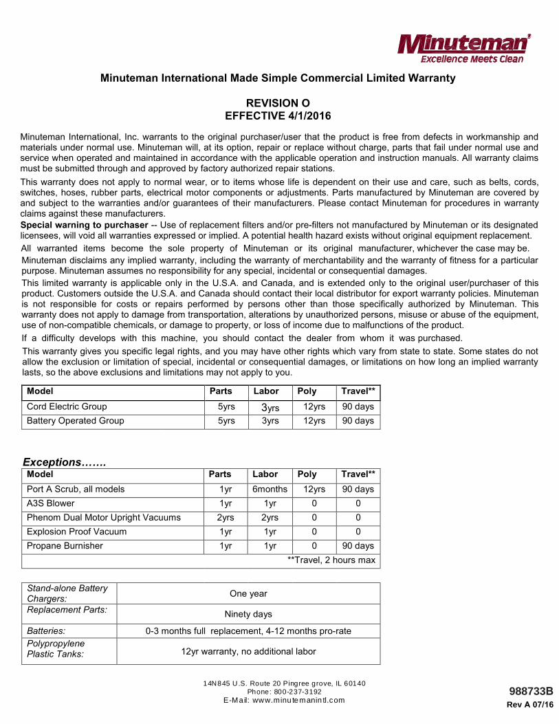
Minuteman International Made Simple Commercial Limited Warranty
REVISION O EFFECTIVE 4/1/2016
Minuteman International, Inc. warrants to the original purchaser/user that the product is free from defects in workmanship and materials under normal use. Minuteman will, at its option, repair or replace without charge, parts that fail under normal use and service when operated and maintained in accordance with the applicable operation and instruction manuals. All warranty claims must be submitted through and approved by factory authorized repair stations.
This warranty does not apply to normal wear, or to items whose life is dependent on their use and care, such as belts, cords, switches, hoses, rubber parts, electrical motor components or adjustments. Parts manufactured by Minuteman are covered by and subject to the warranties and/or guarantees of their manufacturers. Please contact Minuteman for procedures in warranty claims against these manufacturers.
Special warning to purchaser -- Use of replacement filters and/or pre-filters not manufactured by Minuteman or its designated licensees, will void all warranties expressed or implied. A potential health hazard exists without original equipment replacement.
All warranted items become the sole property of Minuteman or its original manufacturer, whichever the case may be.
Minuteman disclaims any implied warranty, including the warranty of merchantability and the warranty of fitness for a particular purpose. Minuteman assumes no responsibility for any special, incidental or consequential damages.
This limited warranty is applicable only in the U.S.A. and Canada, and is extended only to the original user/purchaser of this product. Customers outside the U.S.A. and Canada should contact their local distributor for export warranty policies. Minuteman is not responsible for costs or repairs performed by persons other than those specifically authorized by Minuteman. This warranty does not apply to damage from transportation, alterations by unauthorized persons, misuse or abuse of the equipment, use of non-compatible chemicals, or damage to property, or loss of income due to malfunctions of the product.
If a difficulty develops with this machine, you should contact the dealer from whom it was purchased.
This warranty gives you specific legal rights, and you may have other rights which vary from state to state. Some states do not allow the exclusion or limitation of special, incidental or consequential damages, or limitations on how long an implied warranty lasts, so the above exclusions and limitations may not apply to you.
Model Parts Labor Poly Travel**
Cord Electric Group 5yrs 3yrs 12yrs 90 days
Battery Operated Group 5yrs 3yrs 12yrs 90 days
Exceptions……. Model Parts Labor Poly Travel**
Port A Scrub, all models 1yr 6months 12yrs 90 days
A3S Blower 1yr 1yr 0 0
Phenom Dual Motor Upright Vacuums 2yrs 2yrs 0 0
Explosion Proof Vacuum 1yr 1yr 0 0
Propane Burnisher 1yr 1yr 0 90 days
**Travel, 2 hours max
Stand-alone Battery Chargers:
One year
Replacement Parts: Ninety days
Batteries: 0-3 months full replacement, 4-12 months pro-rate
Polypropylene Plastic Tanks: 12yr warranty, no additional labor