parts catalog cummins dqad dqae dqaf spec... · board, printed circuit − genset communications...
TRANSCRIPT
Printed in U.S.A.
Parts CatalogModelsDQAD (Spec B)DQAE (Spec B)DQAF (Spec B)
960−0218B 1-2004
Redistribution or publication of this documentby any means, is strictly prohibited.

The following symbols are used in Cummins PowerGeneration manuals to alert users to the potentiallydangerous conditions relating to maintenance ofequipment and replacement of parts. Please readand observe.
This symbol warns of immediatehazards which will result in severepersonal injury or death.
This symbol refers to a hazard orunsafe practice which can resultin severe personal injury or death.
This symbol refers to a hazard orunsafe practice which can resultin severe personal injury or prod-uct or property damage.
This catalog covers models produced under theCummins /Onan and Cummins Power Genera-tion brand names.
To avoid errors or delay in filling your parts order, al-ways give the MODEL, SPEC NO. and SERIAL NO.from the Cummins Power Generation nameplate.
For handy reference, insert your nameplate in-formation in the spaces below.
MODEL AND SPEC NO.
SERIAL NO.
DIGITAL CONTROL SOFTWARE VERSIONAND DATE (IF APPLICABLE)
Contact with USED ENGINE OILS has been identified by a United States federal agency and some USAstate agencies as causing CANCER or REPRODUCTIVE TOXICITY. When checking or changing engineoils take all necessary precautions not to ingest, breathe the fumes or contact the used oil.
Contact with ASBESTOS has been identified by a United States federal agency and some USA state agen-cies as causing CANCER or REPRODUCTIVE TOXICITY. When handling engine gaskets take all neces-sary precautions not to ingest, breathe or contact the dust from the gaskets! Use adequate ventilationand wear protective gloves, masks and clothing!
Contact with BENZINE and LEAD, found in gasoline, fuel additives and solvents has been identified bya United States federal agency and some USA state agencies as causing CANCER or REPRODUCTIVETOXICITY. When checking, draining or adding gasoline and fuel additives or using solvents take all nec-essary precautions not to ingest, breathe the fumes or contact the liquids. Use adequate ventilation andwear protective gloves, masks and protective clothing!
PSP-1
Service and repair of Cummins Power Generation equipment must be performed by trained, experiencedpersonnel only. Improper service or repair may result in property damage, severe personal injury ordeath. Do not use this catalog as a guide to servicing your equipment. Read and follow the IMPORTANTSAFETY INSTRUCTIONS in the Service Manual appropriate for the equipment you are working on.
Redistribution or publication of this documentby any means, is strictly prohibited.

1
Introduction
This catalog applies to Cummins Power Generation Generator Models DQAD, DQAE and DQAF as listed in the GeneratorSet Data Table. Parts are arranged in groups of related items and each illustrated part is identified by a reference numbercorresponding to the same reference number in the parts list. Parts illustrations are typical. Unless otherwise mentionedin the description or page heading, parts are interchangeable between models. Throughout this catalog left and right sidesare determined by facing the engine end (front) of the set unless noted in the description column.
Engine parts that have been modified or added by Cummins Power Generation are identified in this catalog. All otherengine replacement parts must be ordered from the engine manufacturer by referring to the engine manufacturer’s name-plate and supplying all available information. Contact your nearest engine parts distributor for assistance in ordering re-placement parts.
Replacement Engine
Cummins Power GenerationGenerator Model
Cummins Engine Model
DQAD QSM11−G1
DQAE QMS11−G2
DQAF QMS11−G2
Generator Set Data Table
Model and Electrical Data Batter yModel andSpecification Watts Volts Hertz Wire Phase
BatteryVoltage
220DQAD/*250DQAD/*
220,000250,000
##
5060
1212
33
24VDC24VDC
250DQAE/*275DQAE/*
250,000275,000
##
5060
1212
33
24VDC24VDC
275DQAF/*300DQAF/*
275,000300,000
##
5060
1212
33
24VDC24VDC
* − The diagonal line (/) in the model and specification number separates generator set characteristics from thespecification number and letter. The specification number denotes customer requested options or deviations from thestandard model. The specification letter advances (A to B, B to C, etc.) with major manufacturing changes.
# − Broad range reconnectible
Copyright�2001 Cummins Power Generation. All rights reserved.
Redistribution or publication of this documentby any means, is strictly prohibited.

2
Engine Parts Catalog Ordering Information
A parts catalog listing all of the engine parts is available for purchase fromthe engine supplier.
To order an engine parts catalog, please contact the following suppliers.
Cummins Powered Generator Sets:
Cummins Literature ServicePhone 800-646-5609 orOutside the US or Canada phone 502-454-6660Please have the Cummins engine serial number available.
Ford Powered Generator Sets:
Northern Power ProductsPhone 800-284-6247 orOutside the US or Canada phone 651-452-8900Please have the Ford engine model number available.
Redistribution or publication of this documentby any means, is strictly prohibited.

Index
3
AAccessories, 102Adapter, Generator, 65Alarm, Low Fuel, 22Alarm, Overfill, 21Ammeter, 59
BBar, Neutral, 86Bar, Neutral − Circuit Breaker − Without Enclosure, 97Basin, Rupture, 23Board, Printed Circuit − Analog, 61Board, Printed Circuit − Customer Interface, 61Board, Printed Circuit − Digital, 61Board, Printed Circuit − Display, 59Board, Printed Circuit − Engine Interface, 61Board, Printed Circuit − Fuel Tank Control, 16Board, Printed Circuit − Genset Communications Module, 70Box, Circuit Breaker − With F200 − F205 Enclosure, 99Box, Circuit Breaker − Without Enclosure, 97Box, Control, 61Box, Entrance, 51Bracket, Battery, 101Breaker, Circuit − UL Listed, IEC Conformity, 95Breaker, Circuit − Fuel Tank Control, 16Bus, Power Transformer, 61
CCable, Battery − Starter, 50Cable, Ribbon − Control Door, 59Cap, Fuel − Day Tank − With Control, 14Cap, Fuel − Day Tank − With Pump and Control, 13Cap, Fuel − Day Tank − Without Pump and Control, 15Cartridge, Heater − Generator, 63Cleaner, Air − Heavy Duty, 11Cleaner, Air − Standard, 10Clip, Socket Mounting − Relay, 68Control Assembly, 55Control, Coolant Heater, 33Control, Fuel Tank − Components, 16Control, Fuel Tank − Day Tank − With Control, 14Control, Fuel Tank − Day Tank − With Pump and Control, 13Cooler, Fuel − Radiator, 37Cover, Battery, 91Cover, Box − Circuit Breaker − Without Enclosure, 97Cover, Control Box, 54Cover, Control Housing − Side − Upper, 54Cushion, Vibration − Engine End, 44Cushion, Vibration − Generator End, 44
DDisc, Drive − Generator, 65Door, Control, 59Duct, Air − Aluminum, 77
EElbow, Exhaust, 25Element, Air Cleaner − Heavy Duty − Inner and Outer, 11Enclosure (F183), 39Enclosure − Aluminum, 43Enclosure − Aluminum Air Discharge − Horizontal, 83Enclosure − Aluminum Air Discharge − Vertical, 81Enclosure − Steel, 41Enclosure − Steel Air Discharge − Horizontal, 82Enclosure − Steel Air Discharge − Vertical, 80Engine Accessories, 9
FFan, Engine, 37Fuel Transfer − Pump and Control, 20Fuse, Control Box, 61
GGasket, Door, 61Gauge, Liquid Level − Day Tank − With Control, 14Gauge, Liquid Level − Day Tank − With Pump and Control, 13Generator (Assembly), 65Generator (Complete Replacement Part Numbers), 66Guard, Radiator, 37
HHarness, Wiring − Control Door, 59Harness, Wiring − Coolant Heater Control, 33Harness, Wiring − Engine to Control, 93Harness, Wiring − Fuel Tank Control, 16Harness, Wiring − Fuel Tank Control to Starter − Day Tank −
With Control, 14Harness, Wiring − Fuel Tank Control to Starter − Day Tank −
With Pump and Control, 13Harness, Wiring − Fuel Transfer Pump to Fuel Tank Control −
Day Tank − With Pump and Control, 13Harness, Wiring − Generator, 65Harness, Wiring − Interconnect − Non−Paralleling, 67Harness, Wiring − Interconnect − Paralleling, 67Heater, Control, 56, 61Heater, Coolant, 31Heater, Generator, 63Heater, Oil Pan, 34
Redistribution or publication of this documentby any means, is strictly prohibited.

Index
4
Hose, Oil Drain, 9Hose, Radiator, 37Housing, Control, 53
IIsolator, Vibration, 67Isolator, Vibration − Control Box, 61Isolator, Vibration − Day Tank − With Control, 14Isolator, Vibration − Day Tank − With Pump and Control, 13Isolator, Vibration − Day Tank − Without Pump and Control, 15
KKey, Replacement − Selector Switch, 59Kit, Repair − Fuel Transfer Pump, 13
LLabel, Control, 100Lamp, Indicator − Fuel Tank Control, 16Line, Flexible − Fuel, 101Louver − Aluminum Air Inlet, 72Louver − Aluminum Rain Hood, 76Louver − Aluminum Weather and Acoustic, 74Louver − Steel Air Inlet, 71Louver − Steel Rain Hood, 75Louver − Steel Weather and Acoustic, 73Louver Assembly − Aluminum, 79Louver Assembly − Steel, 78
MMeter, Frequency, 59Motor − Fuel Tank Pump − Day Tank − With Fuel Tank Pump
and Control, 13Mount, Terminal Rail, 67Mounting System, 47Mounting System − Aluminum Enclosure, 49Muffler − With F183 Enclosure, 26Muffler, Exhaust (Weather Protective, Level I Sound Enclosure
− F200, F201, F203, F204), 27Muffler, Exhaust − Critical (Level II Sound Enclosure − F202,
F204), 28
PPaint, 6Paint, Sandstone, 6Panel, Distribution, 89Pickup, Magnetic, 9
Pump, Fuel Transfer − Day Tank − With Pump and Control, 13Pyrometer, 90
RRadiator, 37Rail, Terminal, 67Receptacle, External, 85Rectifier, Power − Control Heater, 61Relay, Customer, 68Relay, Ground Fault, 69Relay, Power − Coolant Heater Control, 33Relay, Pump − Fuel Tank Control, 16Rotor, Exciter − Generator, 65Rotor, Generator, 66
SSealant, Thread, 6Sender, Oil Pressure, 9Sender, Oil Temperature, 9Skid, 44Skid, Lifting, 45Socket, Relay, 68Solenoid, Pilot, 9Standoff, Board − Printed Circuit, 61Starter, Electric, 50Stator, Exciter − Generator, 65Stator, Generator, 66Strap, Bond − Control Box, 61Strap, Ground − Skid, 44Switch, Basin − Low Fuel Alarm, 22Switch, Emergency Stop, 84Switch, Float − Basin, 24Switch, Float − Day Tank − With Control, 14Switch, Float − Day Tank − With Pump and Control, 13Switch, Low Engine Coolant Temperature, 9Switch, Pushbutton − Emergency Stop, 59Switch, Rocker − Fuel Tank Control, 16Switch, Selector − Key Operated, 59Switch, Selector − Run/Off/Auto, 59
TTank, Day − With Control, 14Tank, Day − With Pump and Control, 13Tank, Day − Without Pump and Control, 15Tank, Fuel, 18, 19Thermostat − Coolant Heater, 31Transformer, 24VAC, 87Transformer, Current, 88Tube, Radiator, 37
Redistribution or publication of this documentby any means, is strictly prohibited.

Index
5
VValve Assembly, Float − Day Tank − Without Pump and
Control, 15Valve, Oil Drain − Radiator, 37Valve, Shutoff − Oil Drain, 9
Voltmeter − Control Cabinet Door, 59
WWattmeter, 59
Redistribution or publication of this documentby any means, is strictly prohibited.

6
Abbreviations
Some of the following abbreviations may be used throughout this Parts Catalog:
AC Alternating CurrentAmp AmpereA/R As RequiredAVR Automatic Voltage RegulatorAWG American Wire GaugeDC Direct CurrentDeg DegreeEFC Electronic Fuel ControlEIT External/Internal ToothEPROM Erasable Programmable Read
Only MemoryET External ToothGFI Ground Fault InterrupterID Inside DiameterIEC International Electrotechnical CommissionIT Internal ToothkW KilowattLPG Liquid Petroleum GasLT LeftM(meter number) Meter
mm MillimeterMOH Mobile Off HighwayNFS Not For SaleNPT National Pipe ThreadOD Outside Diameteroz. OuncePC Printed CircuitPh PhasePMG Permanent Magnet GeneratorPT/CT Potential Transformer/Current
TransformerRFI Radio Frequency InterferenceRT RightSpec SpecificationThk ThickUL Underwriters Laboratories Inc.UNC Union National CoarseUNF Union National FineVAC Volts Alternating CurrentVDC Volts Direct CurrentW/(ET, IT, EIT) With
Paint and Thread Sealant
REF PART QTY PART REF PART QTY PARTNO. NO. USED DESCRIPTION NO. NO. USED DESCRIPTION
Onan Green Enamel(Non−Metallic)
525−0305 − 12 oz. PressurizedSpray Can
525−0306 − Quart Can525−0304 − Gallon Can
518−0601 − Sealant, Thread (6 ml Tube)525−0749 − Paint, Sandstone
Redistribution or publication of this documentby any means, is strictly prohibited.

7
This Page Intentionally Left Blank.
Redistribution or publication of this documentby any means, is strictly prohibited.

8
Engine Accessories
3
24
22
13
23
6
19
21
20
2119
18
1716
12
14
1
4
2
1511
1
4
10
5
8
7
10
9
13
23
23
13
23
25
26
Redistribution or publication of this documentby any means, is strictly prohibited.
9
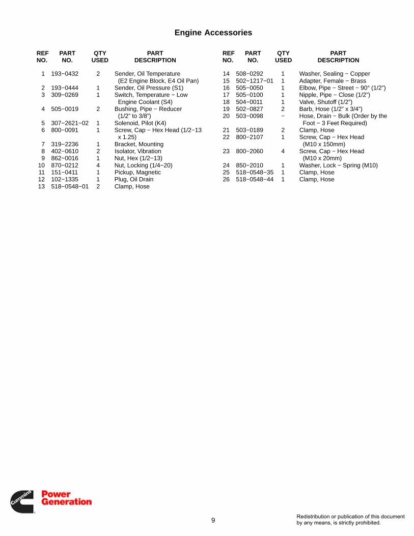
Engine Accessories
REF PART QTY PART REF PART QTY PARTNO. NO. USED DESCRIPTION NO. NO. USED DESCRIPTION
1 193−0432 2 Sender, Oil Temperature(E2 Engine Block, E4 Oil Pan)
2 193−0444 1 Sender, Oil Pressure (S1)3 309−0269 1 Switch, Temperature − Low
Engine Coolant (S4)4 505−0019 2 Bushing, Pipe − Reducer
(1/2” to 3/8”)5 307−2621−02 1 Solenoid, Pilot (K4)6 800−0091 1 Screw, Cap − Hex Head (1/2−13
x 1.25)7 319−2236 1 Bracket, Mounting8 402−0610 2 Isolator, Vibration9 862−0016 1 Nut, Hex (1/2−13)
10 870−0212 4 Nut, Locking (1/4−20)11 151−0411 1 Pickup, Magnetic12 102−1335 1 Plug, Oil Drain13 518−0548−01 2 Clamp, Hose
14 508−0292 1 Washer, Sealing − Copper15 502−1217−01 1 Adapter, Female − Brass16 505−0050 1 Elbow, Pipe − Street − 90° (1/2”)17 505−0100 1 Nipple, Pipe − Close (1/2”)18 504−0011 1 Valve, Shutoff (1/2”)19 502−0827 2 Barb, Hose (1/2” x 3/4”)20 503−0098 − Hose, Drain − Bulk (Order by the
Foot − 3 Feet Required)21 503−0189 2 Clamp, Hose22 800−2107 1 Screw, Cap − Hex Head
(M10 x 150mm)23 800−2060 4 Screw, Cap − Hex Head
(M10 x 20mm)24 850−2010 1 Washer, Lock − Spring (M10)25 518−0548−35 1 Clamp, Hose26 518−0548−44 1 Clamp, Hose
Redistribution or publication of this documentby any means, is strictly prohibited.

10
Air CleanerStandard
1
2
3 4
56
7
8
9
10
11
12
13
1516
17
18 18 19
14
15
REF PART QTY PART REF PART QTY PARTNO. NO. USED DESCRIPTION NO. NO. USED DESCRIPTION
1 140−3288−02 1 Cleaner, Air2 140−2656 1 Bracket, Air Cleaner3 140−2655 1 Bracket, Air Cleaner4 140−3343−02 1 Bracket, Air Cleaner5 503−2276 1 Elbow, Reducer − 45° (5.5 x 4)6 140−2102 1 Elbow, Reducer − 90° (7 x 5.5)7 140−3362−02 1 Tube, Air Cleaner − Inlet8 526−0112 4 Washer, Flat (5/8)9 850−0070 4 Washer, Lock − Split (5/8)
10 800−0130 4 Screw, Cap − Hex Head (M12 x1.75 x 25)
11 526−2140 2 Washer, Flat (M12)
12 850−2012 2 Washer, Lock − Split (M12)13 800−2111 2 Screw, Cap − Hex Head (M12 x
1.75 x 25)14 821−6003−02 4 Screw, Hex Head (M8 x 1.25 x
20)15 821−6004−01 4 Screw, Hex Head (M10 x 1.5 x
20)16 870−2065−04 4 Nut, Hex − Flange17 503−1870−14 1 Clamp, Hose18 503−1870−11 2 Clamp, Hose19 503−1870−07 1 Clamp, Hose
Redistribution or publication of this documentby any means, is strictly prohibited.

11
Air CleanerHeavy Duty
18
1
2
3
4
5 6
78
9
10
11
12
13
14
15
16
17
1819
20
2120 20
22
2324
25
REF PART QTY PART REF PART QTY PARTNO. NO. USED DESCRIPTION NO. NO. USED DESCRIPTION
1 140−2637 1 Cleaner, Air (Includes Elements)2 140−2636 1 Element, Filter (Outer)3 140−2638 1 Element, Filter (Inner)4 140−2656 1 Bracket, Air Cleaner5 140−2655 1 Bracket, Air Cleaner6 140−3343−02 1 Bracket, Air Cleaner7 503−2276 1 Elbow, Reducer − 45° (5.5 x 4)8 140−1415 1 Elbow − 90°9 140−3388−02 1 Tube, Air Cleaner − Inlet
10 526−0112 4 Washer, Flat (5/8)11 850−0070 4 Washer, Lock − Split (5/8)12 800−0130 4 Screw, Cap − Hex Head (M12 x
1.75 x 25)13 526−2140 2 Washer, Flat (M12)14 850−2012 2 Washer, Lock − Split (M12)
15 800−2111 2 Screw, Cap − Hex Head (M12 x1.75 x 25)
16 821−6003−02 4 Screw, Hex Head (M8 x 1.25 x20)
17 870−2065−03 4 Nut, Hex − Flange (M8 x 1.5)18 821−6004−01 4 Screw, Hex Head (M10 x 1.5 x
20)19 870−2065−04 4 Nut, Hex − Flange20 503−1870−11 3 Clamp, Hose21 503−1870−07 1 Clamp, Hose22 140−1347 1 Cap, Air Cleaner23 140−1260 1 Fitting, Safety Filter24 140−1548 1 Indicator, Service25 140−0757 2 Clamp, Air Cleaner
Redistribution or publication of this documentby any means, is strictly prohibited.

12
Day TankWith Pump and Control
17
16
11
18
5 1
7
20
21
7
10
9
4
7
8
22
15
6
139
19
23
12
14
Redistribution or publication of this documentby any means, is strictly prohibited.

13
Day TankWith Pump and Control
REF PART QTY PART REF PART QTY PARTNO. NO. USED DESCRIPTION NO. NO. USED DESCRIPTION
1 415−0727 1 Tank, Day (19 Gallons)2 415−0565−15 1 Gauge, Liquid Level3 159−1208−01 1 Cap, Fuel4 399−0117 1 Pump, Fuel Transfer (Includes
Coupler) (P103)399−0121 1 Kit, Repair − Fuel Tank Pump
(Includes Lip Seal,Bearings, Gasket, DriveGear, Idle Gear andCoupler) (Not Illustrated)
399−0122 1 Coupler, Pump (Drive PieceBetween Motor and Pump)(Not Illustrated)
399−0123 1 Pump (Not Illustrated)399−0124 1 Motor (Not Illustrated)
5 159−1299 1 Bracket, Mounting6 821−5002−04 4 Screw, Self−Locking − Hex
Washer Head (1/4−20 x 5/8”)7 870−0212 13 Nut, Locking − Hex Head
(1/4−20)8 503−1660−04 1 Hose, Fuel (5/8” ID x 18”)9 503−0183 2 Clamp, Hose
10 502−0943 1 Connector, Hose
11 308−0913−06 1 Switch, Float (5 Float)12 505−0172 1 Nipple, Pipe − Close (2”)13 415−0566−15 1 Pipe, Suction14 505−0120 1 Elbow, Pipe − Street
(3/8” x 90°)15 505−0050 1 Elbow, Pipe − Street
(1/2” x 90°)16 Harness, Wiring
338−2800 1 Fuel Transfer Pump to FuelTank Control (5 Wire,49−1/2”)
338−2809 1 Fuel Tank Control to Starter(2 Wire, 70”)
17 625−2141−01 1 Control, Fuel Tank (SeeSeparate Page ForComponents)
18 821−0030 2 Screw, Self−Locking − HexWasher Head (3/8−16 x 1”)
19 502−0942 1 Elbow, Hose − Brass − Barbed20 402−0610 6 Isolator, Vibration21 337−2402 1 Cable, Ground (5−1/2”)22 505−0248 1 Elbow, Pipe − Street
(1/2” x 45°)
Redistribution or publication of this documentby any means, is strictly prohibited.

14
Day TankWith Control
135
11
7
14
4
6
15
16
6
1
10
2
12
9
3
8
17
REF PART QTY PART REF PART QTY PARTNO. NO. USED DESCRIPTION NO. NO. USED DESCRIPTION
1 415−0727 1 Tank, Day (19 Gallons)2 415−0565−15 1 Gauge, Liquid Level3 159−1208−01 Cap, Fuel4 159−1299 1 Bracket, Mounting5 821−5002−04 4 Screw, Self−Locking − Hex
Washer Head (1/4−20 x 5/8”)6 870−0212 9 Nut, Locking − Hex Head (1/4−20)7 308−0913−06 1 Switch, Float (5 Float)8 505−0172 1 Nipple, Pipe − Close (2”)9 415−0566−15 1 Pipe, Suction
10 505−0120 1 Elbow, Pipe − Street (3/8” x 90°)11 505−0050 1 Elbow, Pipe − Street (1/2” x 90°)
12 338−2809 1 Harness, Wiring − Fuel TankControl to Starter (2 Wire, 70”)
13 625−2141−01 1 Control, Fuel Tank (SeeSeparate Page For Components)
14 821−0030 2 Screw, Self−Locking − HexWasher Head (3/8−16 x 1”)
15 402−0610 6 Isolator, Vibration16 337−2402 1 Cable, Ground (5−1/2”)17 505−0248 1 Elbow, Street (1/2” x 45°)
Redistribution or publication of this documentby any means, is strictly prohibited.

15
Day TankWithout Pump and Control
1
9
2 10
3
11
4
12
13
14
7
15
8
6
5
2021
16
22
1819
4
17
23
24
REF PART QTY PART REF PART QTY PARTNO. NO. USED DESCRIPTION NO. NO. USED DESCRIPTION
1 415−0728 1 Tank, Day (19 Gallons)2 159−1208−01 1 Cap, Fuel3 159−1299 1 Bracket, Mounting4 870−0212 9 Nut, Locking − Hex Head
(1/4−20)5 867−0028 8 Nut, Hex (#10−32)6 853−1008 8 Washer, Lock − W/ET (#10)7 505−0172 1 Nipple, Pipe − Close (2”)8 415−0566−15 1 Pipe, Suction9 505−0120 1 Elbow, Street − 90° (3/8”)
10 505−0050 1 Elbow, Street − 90° (1/2”)11 821−0030 2 Screw, Self−Locking − Hex
Washer Head (3/8−16 x 1”)12 402−0610 6 Isolator, Vibration13 337−2402 1 Cable, Ground (5−1/2”)
14 415−0660 1 Gasket15 526−0008 8 Washer, Flat (#10)16 415−0657 1 Valve Assembly, Float
(Includes Parts Marked *)17 415−0656−21 1 *Seal, Ring18 415−0650−01 1 *Body, Valve19 415−0651−19 1 *Pin, Roll20 415−0652 1 *Ball, Float21 864−0011 1 *Nut, Jam (1/4−20)22 415−0654 1 *Arm, Float23 415−0655 1 *Ball, Steel24 505−0248 1 Elbow, Street (1/2” x 45°)
* − Parts Included in 415−0657 Float Valve Assembly
Redistribution or publication of this documentby any means, is strictly prohibited.

16
Fuel Tank Control
213
12
13
9
8
5
41
17
7 6
18
103
14
11
16
15
REF PART QTY PART REF PART QTY PARTNO. NO. USED DESCRIPTION NO. NO. USED DESCRIPTION
625−2141−01 1 Control, Fuel Tank − Complete(Includes Parts Listed Below)
1 319−0486 1 Box, Control2 319−0485 1 Cover, Box3 307−2677−02 1 Relay, Pump (K130)4 322−0403−02 1 Light, Assembly, Indicator −
7 Light (Includes WiringHarness)
5 322−0369−02 1 Lamp, Indicator − Replacement6 308−0912 1 Switch, Rocker (On/Off/
Emergency Run) (S102)7 308−0852 1 Switch, Rocker (Reset/Off/Test)
(S111)8 320−1653 1 Breaker, Circuit − DC (Single
Pole) (CB107)
9 320−1654 1 Breaker, Circuit − AC (DoublePole) (CB101)
10 300−3464 1 Board, Printed Circuit11 870−0458 4 Spacer, Board − Printed Circuit12 338−2382 1 Harness, Wiring − Control Box13 815−0350 5 Screw, Self−Tapping − Slotted
Hex Washer Head (#10−32 x3/8”)
14 812−0075 2 Screw, Machine − Round Head(#8−32 x 1/4”)
15 815−0385 2 Screw, Machine − Round Head(#6−32 x 1/2”)
16 332−2605 2 Jumper, Terminal17 331−0027 2 Connector, Romex18 331−0042 1 Connector, Knockout
Redistribution or publication of this documentby any means, is strictly prohibited.

17
This Page Intentionally Left Blank.
Redistribution or publication of this documentby any means, is strictly prohibited.
18
Fuel Tank
1
23 4
5
Redistribution or publication of this documentby any means, is strictly prohibited.

19
Fuel Tank
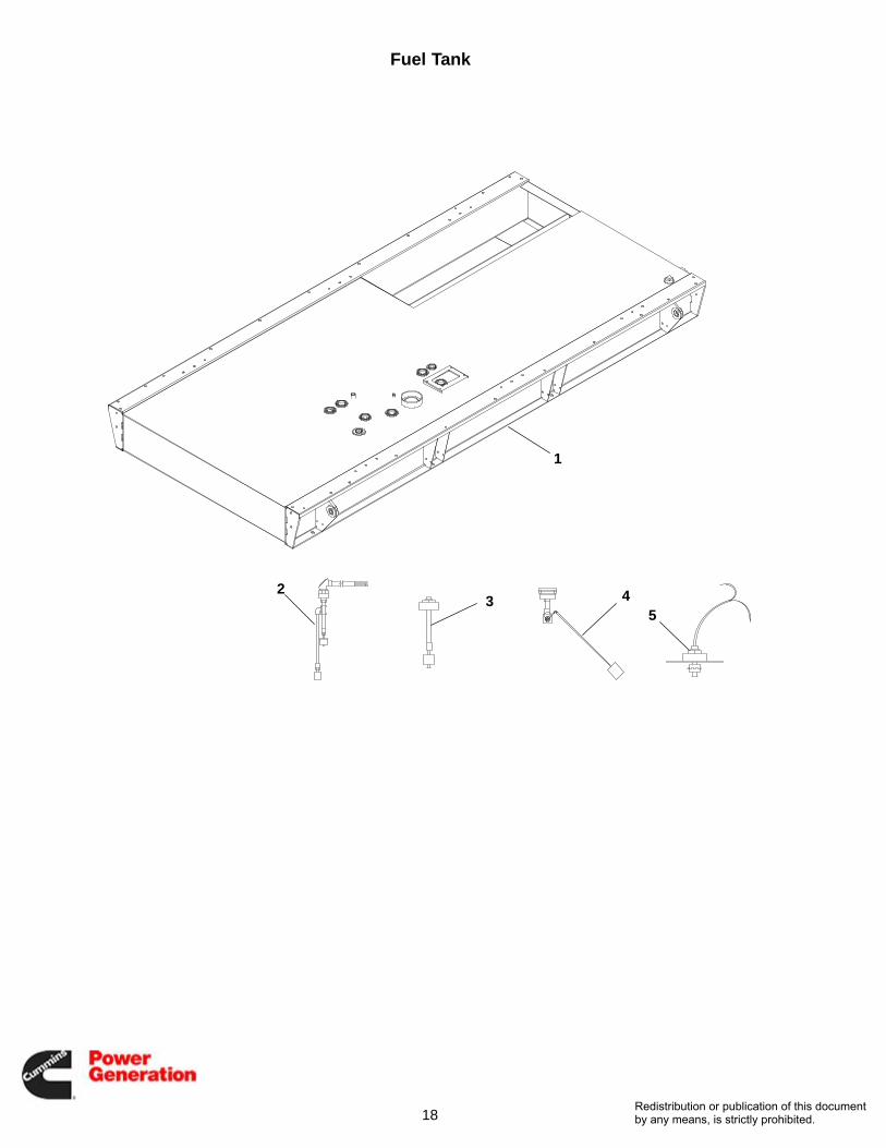
REF PART QTY PART REF PART QTY PARTNO. NO. USED DESCRIPTION NO. NO. USED DESCRIPTION
1 Tank, FuelStandard (Chicago)
159−1573−01 1 300 Gallon159−1573−02 1 400 Gallon159−1573−03 1 500 Gallon159−1573−04 1 600 Gallon159−1573−05 1 660 Gallon159−1573−06 1 720 Gallon159−1577−01 1 1470 Gallon
California159−1573−11 1 300 Gallon159−1573−12 1 400 Gallon159−1573−13 1 500 Gallon159−1573−14 1 600 Gallon159−1573−15 1 660 Gallon159−1573−16 1 720 Gallon
Florida159−1573−21 1 300 Gallon159−1573−22 1 400 Gallon159−1573−23 1 500 Gallon159−1573−24 1 600 Gallon159−1573−25 1 660 Gallon159−1573−26 1 720 Gallon
2 Switch, Level − High and Low309−0701−01 1 300 Gallon Tank309−0701−02 1 400 Gallon Tank309−0701−03 1 500 Gallon Tank309−0701−04 1 600 Gallon Tank309−0701−05 1 660 Gallon Tank309−0701−07 1 720 Gallon Tank309−0701−08 1 1470 Gallon Tank
3 Switch, Level − Rupture Basin309−0702−01 1 300 Gallon Tank309−0702−02 1 400 Gallon Tank309−0702−03 1 500 Gallon Tank309−0702−04 1 600 Gallon Tank309−0702−05 1 660 Gallon Tank309−0702−07 1 720 Gallon Tank309−0702−08 1 1470 Gallon Tank
4 Gauge − Fuel Level420−0609−01 1 300 Gallon Tank420−0609−02 1 400 Gallon Tank420−0609−03 1 500 Gallon Tank420−0609−04 1 600 Gallon Tank420−0609−05 1 660 Gallon Tank420−0609−07 1 720 Gallon Tank420−0609−08 1 1470 Gallon Tank
5 Switch, Level − Critical High309−0708−01 1 300−500 Gallon Tank309−0708−02 1 600−850 Gallon Tank
Redistribution or publication of this documentby any means, is strictly prohibited.
20
Fuel TransferPump and Control
1
2
3
4
5
6
7
9
9
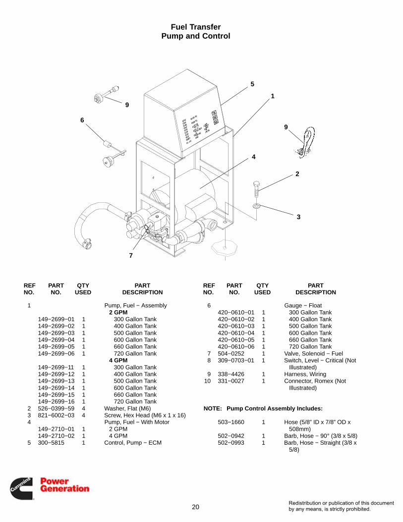
REF PART QTY PART REF PART QTY PARTNO. NO. USED DESCRIPTION NO. NO. USED DESCRIPTION
1 Pump, Fuel − Assembly2 GPM
149−2699−01 1 300 Gallon Tank149−2699−02 1 400 Gallon Tank149−2699−03 1 500 Gallon Tank149−2699−04 1 600 Gallon Tank149−2699−05 1 660 Gallon Tank149−2699−06 1 720 Gallon Tank
4 GPM149−2699−11 1 300 Gallon Tank149−2699−12 1 400 Gallon Tank149−2699−13 1 500 Gallon Tank149−2699−14 1 600 Gallon Tank149−2699−15 1 660 Gallon Tank149−2699−16 1 720 Gallon Tank
2 526−0399−59 4 Washer, Flat (M6)3 821−6002−03 4 Screw, Hex Head (M6 x 1 x 16)4 Pump, Fuel − With Motor
149−2710−01 1 2 GPM149−2710−02 1 4 GPM
5 300−5815 1 Control, Pump − ECM
6 Gauge − Float420−0610−01 1 300 Gallon Tank420−0610−02 1 400 Gallon Tank420−0610−03 1 500 Gallon Tank420−0610−04 1 600 Gallon Tank420−0610−05 1 660 Gallon Tank420−0610−06 1 720 Gallon Tank
7 504−0252 1 Valve, Solenoid − Fuel8 309−0703−01 1 Switch, Level − Critical (Not
Illustrated)9 338−4426 1 Harness, Wiring
10 331−0027 1 Connector, Romex (NotIllustrated)
NOTE: Pump Control Assembly Includes:
503−1660 1 Hose (5/8” ID x 7/8” OD x508mm)
502−0942 1 Barb, Hose − 90° (3/8 x 5/8)502−0993 1 Barb, Hose − Straight (3/8 x
5/8)
Redistribution or publication of this documentby any means, is strictly prohibited.

21
Overfill Alarm
1
2
34
5
6
7
84
9
6
10
11
12
13
14
REF PART QTY PART REF PART QTY PARTNO. NO. USED DESCRIPTION NO. NO. USED DESCRIPTION
333−0683 1 Alarm − Assembly − 24VDC(Includes all the FollowingExcept Two MountingScrews)
1 319−5056−02 1 Box, Control2 333−0682 1 Horn, Alarm3 307−2817−02 1 Relay4 526−0399−05 9 Washer, Flat5 815−0937 1 Screw, Machine − Pan Head −
Cross Recessed − W/ET(#6−32 x .50)
6 870−0183 5 Nut, Hex − W/ET
7 518−0340 1 Clamp, Cable8 815−0651 4 Screw, Machine − Pan Head −
Cross Recessed − W/ET(#6−32 x .75)
9 508−1195 4 Grommet10 338−4360−01 1 Harness, Alarm11 338−4360−02 1 Harness, Alarm12 098−8120 1 Label, Information13 308−0973 1 Switch, Pushbutton14 821−6002−03 2 Screw, Hex Head − Mounting
(M6 x 1 x 16)
Redistribution or publication of this documentby any means, is strictly prohibited.

22
Low Fuel Alarm
4
3
2
1
REF PART QTY PART REF PART QTY PARTNO. NO. USED DESCRIPTION NO. NO. USED DESCRIPTION
1 308−0963−01 1 Switch, Basin2 505−0026 1 Coupling, Pipe (1/8”)3 505−1458−04 Nipple, Pipe (1/8”)
4 505−1050−01 1 Plug, Pipe − Square Head(1−1/4”)
Redistribution or publication of this documentby any means, is strictly prohibited.

23
Rupture Basin
5
4
3
1
2
REF PART QTY PART REF PART QTY PARTNO. NO. USED DESCRIPTION NO. NO. USED DESCRIPTION
1 159−1390 1 Basin, Rupture2 815−0236 2 Screw, Cap − Hex Head −
Thread Forming(5/16−18 x 5/8”)
3 505−0055 1 Plug, Pipe − Square Head (1/4”)
4 130−3660−01 1 Spacer, Shock Absorber5 815−0836 3 Screw, Cap − Hex Head −
Thread Forming (5/16−18 x1−1/2”)
Redistribution or publication of this documentby any means, is strictly prohibited.
24
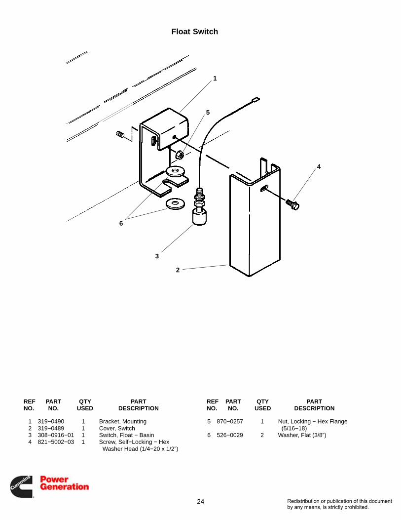
Float Switch
1
2
3
4
5
6
REF PART QTY PART REF PART QTY PARTNO. NO. USED DESCRIPTION NO. NO. USED DESCRIPTION
1 319−0490 1 Bracket, Mounting2 319−0489 1 Cover, Switch3 308−0916−01 1 Switch, Float − Basin4 821−5002−03 1 Screw, Self−Locking − Hex
Washer Head (1/4−20 x 1/2”)
5 870−0257 1 Nut, Locking − Hex Flange(5/16−18)
6 526−0029 2 Washer, Flat (3/8”)
Redistribution or publication of this documentby any means, is strictly prohibited.

25
Exhaust Elbow
1
3
2
3
4
REF PART QTY PART REF PART QTY PARTNO. NO. USED DESCRIPTION NO. NO. USED DESCRIPTION
1 155−2409−04 1 Elbow, Exhaust (5” OD WithThreads)
2 155−1241−01 1 Elbow, Exhaust (5” OD WithoutThreads)
3 503−1575 1 Clamp, V-Band4 155−0658−01 1 Flange, Companion (5”) (Not
Used on All Models)
Redistribution or publication of this documentby any means, is strictly prohibited.

26
MufflerWith F183 Enclosure
1
2
3
45
6
7
7
8
9
10
11
12
13
1415
REF PART QTY PART REF PART QTY PARTNO. NO. USED DESCRIPTION NO. NO. USED DESCRIPTION
1 155−3540 1 Silencer2 155−3510 1 Elbow, Muffler3 155−2441 1 Tubing, Flexible4 155−3509−02 2 Bracket, Muffler5 155−3139 1 Shield, Rain6 155−2062−06 1 Cap, Rain7 155−2159 3 Clamp, Muffler8 821−0033 4 Screw, Locking − Hex Head
(7/16−14 x .75)
9 870−0437 4 Nut, Locking (7/16−14)10 821−5000−05 1 Screw, Hex Head (#10−32)11 870−0320 1 Nut, Whizlock (#10−32)12 800−0048 8 Screw, Cap − Hex Head
(3/8−16 x 3/4)13 526−0030 8 Washer, Flat14 130−5555−02 1 Bracket, Exhaust15 870−0281 8 Nut, Self-Locking − Flange
(3/8−16)
Redistribution or publication of this documentby any means, is strictly prohibited.

27
MufflerF200, F201, F203, F204
Weather Protective, Level I Sound Enclosure
1
2
3
4
5
6
7
8
10
9
REF PART QTY PART REF PART QTY PARTNO. NO. USED DESCRIPTION NO. NO. USED DESCRIPTION
1 155−4022 1 Muffler2 155−2062−06 1 Cap, Rain3 155−3543 1 Clamp, Exhaust4 155−4053 1 Pipe, Exhaust5 526−0174 6 Washer, Flat6 800−2089 6 Screw, Cap − Hex Head (M10 x
1.5 x 40)
7 503−1575 1 Clamp, V-Band8 155−4064 2 Gasket, Muffler9 Guard, Muffler
155−4162 1 Aluminum155−4059−02 1 Steel
10 821−6007−02 10 Screw, Hex Head (M8 x 1.25 x20)
Redistribution or publication of this documentby any means, is strictly prohibited.

28
MufflerCritical
F202, F204Level II Sound Enclosure
1
2
3
4
5
67
8
9
10
11
12
1314
15
16
13
14
15
16
17
18
19
REF PART QTY PART REF PART QTY PARTNO. NO. USED DESCRIPTION NO. NO. USED DESCRIPTION
1 155−4062 1 Muffler2 155−3543 1 Clamp, Exhaust3 155−4053 1 Pipe, Exhaust4 526−0174 6 Washer, Flat5 800−2089 6 Screw, Cap − Hex Head (M10 x
1.5 x 40)6 503−1575 1 Clamp, Hose7 155−4047 1 Muffler − Critical8 155−4045 1 Pipe, Exhaust (8” x 45°)9 155−4026 1 Tailpipe, Exhaust (8”)
10 155−3554 1 Cap, Rain11 Washer, Flat (M12)
526−2140 4 48 and 72 Hour Tank526−2140 8 12 and 24 Hour Tank
12 155−4064 2 Gasket, Muffler13 850−0079 24 Washer, Spring − Lock (3/4)14 800−0156 24 Screw, Cap − Hex Head
(3/4−10 x 2.25)15 862−0008−01 24 Nut, Hex − Heavy (3/4−10)16 155−2500 3 Gasket, Exhaust17 800−2111 4 Screw, Cap − Hex Head (M12 x
1.75 x 25) − 48 and 72 HourTank
18 155−4048−02 2 Bracket, Muffler) − 12 and 24Hour Tank
19 800−2114 8 Screw, Cap − Hex Head (M12 x1.75 x 40) − 12 and 24 HourTank
Redistribution or publication of this documentby any means, is strictly prohibited.

29
This Page Intentionally Left Blank.
Redistribution or publication of this documentby any means, is strictly prohibited.

30
Coolant Heater
1
17
2
18
3
19
4
20
5
21
6
22
7
23
8
9
10
26
12
27
28
29
11
30
12
24
13
14
15
25
16
4
4
3
3
16
16
31
32
Redistribution or publication of this documentby any means, is strictly prohibited.

31
Coolant Heater
REF PART QTY PART REF PART QTY PARTNO. NO. USED DESCRIPTION NO. NO. USED DESCRIPTION
1 502−1259 1 Coupler, Coolant Heater (1/2”)2 502−1257 1 Connector, Hose Barb (For 3/4”
ID Hose)3 503−1634−01 3 Hose, Silicon Rubber
(3/4” ID x 4”)4 503−2157−01 6 Clamp, Hose5 505−0050 2 Elbow, Pipe − 90° (1/2”)6 505−0022 1 Bushing, Reducer (1” to 1/2”)7 505−0100 1 Nipple, Pipe (1/2”)8 502−1260 1 Coupler, Coolant Heater9 502−1261 1 Nipple, Coolant Heater (1/2”)
10 502−0827 1 Connector, Hose Barb (For 3/4”ID Hose)
11 130−5532−02 1 Tube, Coolant Heater12 155−3021 1 Clamp, Coolant Heater13 870−0550−09 2 Nut, Hex Flange (3/8-16)14 319−2918 1 Bracket, Terminal Block15 821−5004−02 2 Screw, Self-Locking − Hex
Washer Head (3/8-16 x 3/4”)16 821−5002−03 5 Screw, Self-Locking − Hex
Washer Head (1/4-20 x 1/2”)17 319−2815 1 Cover, Control18 − 1 Control Assembly, Coolant
Heater (See Separate Page ForComponents)
19 Heater, Coolant333−0634−01 1 4990 Watt333−0634−02 1 6420 Watt
20 815−0539 3 Screw, Machine − Round HeadCross Recessed W/IT (#8-32 x5/8”)
21 870−0131 3 Nut, Hex W/ET (#10-32)22 309−0649 1 Thermostat (S11)23 502−1336 1 Bushing, Reducer (1/2” x 3/8”)24 526−0029 2 Washer, Flat (3/8”)25 332−3196 2 Clamp, ”J” − Retainer − Wiring
Harness (Coolant HeaterControl Box Wiring Harness ToEngine and Main EngineHarness)
26 800−0130 2 Screw, Cap − Hex Head (5/8-11 x1”)
27 850−0070 2 Washer, Lock − Spring (5/8”)28 130−5528−02 1 Bracket, Coolant Heater29 800−0054 2 Screw, Cap − Hex Head (3/8-16 x
2”)30 850−0103 2 Washer, Lock − Spring (3/8”)31 505−0231 1 Coupling, Reducer32 505−0101 1 Nipple, Close
Redistribution or publication of this documentby any means, is strictly prohibited.

32
Coolant Heater Control
1
13
2
14
3
15
23
16
5
17
6
18
7
19
8
20
9
21
10
22
11
23
12
24
20
20
4
24
Redistribution or publication of this documentby any means, is strictly prohibited.

33
Coolant Heater Control
REF PART QTY PART REF PART QTY PARTNO. NO. USED DESCRIPTION NO. NO. USED DESCRIPTION
1 130−4552 1 Cover, Coolant Heater2 338−3923−07 1 Harness, Wiring − AC − Coolant
Heater (From Coolant HeaterBottom To Coolant HeaterControl Box) (Includes ConduitConnectors) (23”)
3 331−0554 2 Connector, Conduit − 90° (3/4”)4 331−0042 1 Connector, Wiring − DC − Romex
(3/4”)5 338−3385 1 Harness, Wiring − DC − Engine
Heater (From Coolant HeaterControl Box To Engine And MainEngine Harness) (Includes PartsMarked *)
6 357−0030 1 *Rectifier (6 Amp) (Located at K11end of harness)
7 323−1718 2 *Pin, Contact8 323−1491 3 *Pin, Contact9 323−1492 2 *Socket, Contact
10 323−1494 1 *Connector, Receptacle (3 Pin)(J3)
11 323−1502 1 *Wedge, Receptacle (Used withJ3)
12 323−1504 1 *Connector, Plug (2 Pin) (P4)13 323−1500 1 *Wedge, Plug (Used With P4)14 323−1652 1 *Connector, Plug − 2−Way (2 Pin)
(P11)15 323−1445 2 *Seal, Cable (Used With P11)16 517−0138−02 3 Plug, Hole (Fits 1−1/8” Hole)17 319−2814 1 Box, Terminal18 332−3440 1 Jumper, Terminal19 307−2859 1 Relay, Power − 24VDC (K11)20 815−0464 4 Screw, Machine − Round Head
Cross Recessed W/IT − ThreadForming (#8-32 x 1”)
21 332−1469 1 Strip, Marker22 332−1468 1 Block, Terminal − 12 Place (TB1)23 331−0555 2 Nut, Connector Lock (3/4-14)24 331−0570 1 Connector, Conduit
*−Parts Included in 338−3385 DC Engine Heater Wiring Harness
Redistribution or publication of this documentby any means, is strictly prohibited.
34
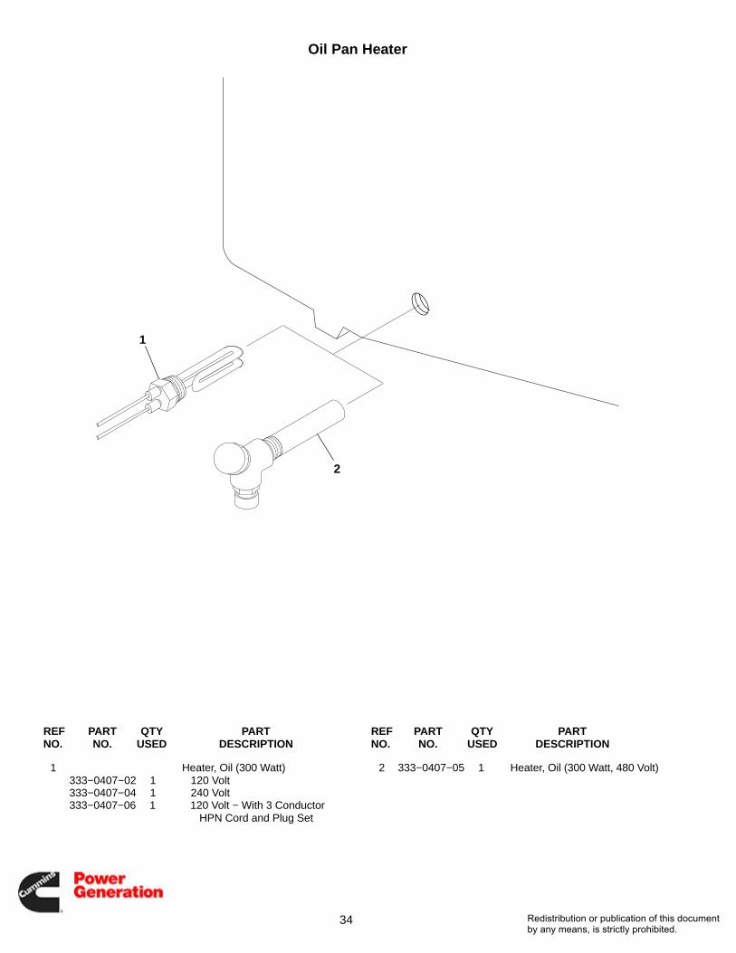
Oil Pan Heater
2
1
REF PART QTY PART REF PART QTY PARTNO. NO. USED DESCRIPTION NO. NO. USED DESCRIPTION
1 Heater, Oil (300 Watt)333−0407−02 1 120 Volt333−0407−04 1 240 Volt333−0407−06 1 120 Volt − With 3 Conductor
HPN Cord and Plug Set
2 333−0407−05 1 Heater, Oil (300 Watt, 480 Volt)
Redistribution or publication of this documentby any means, is strictly prohibited.
35
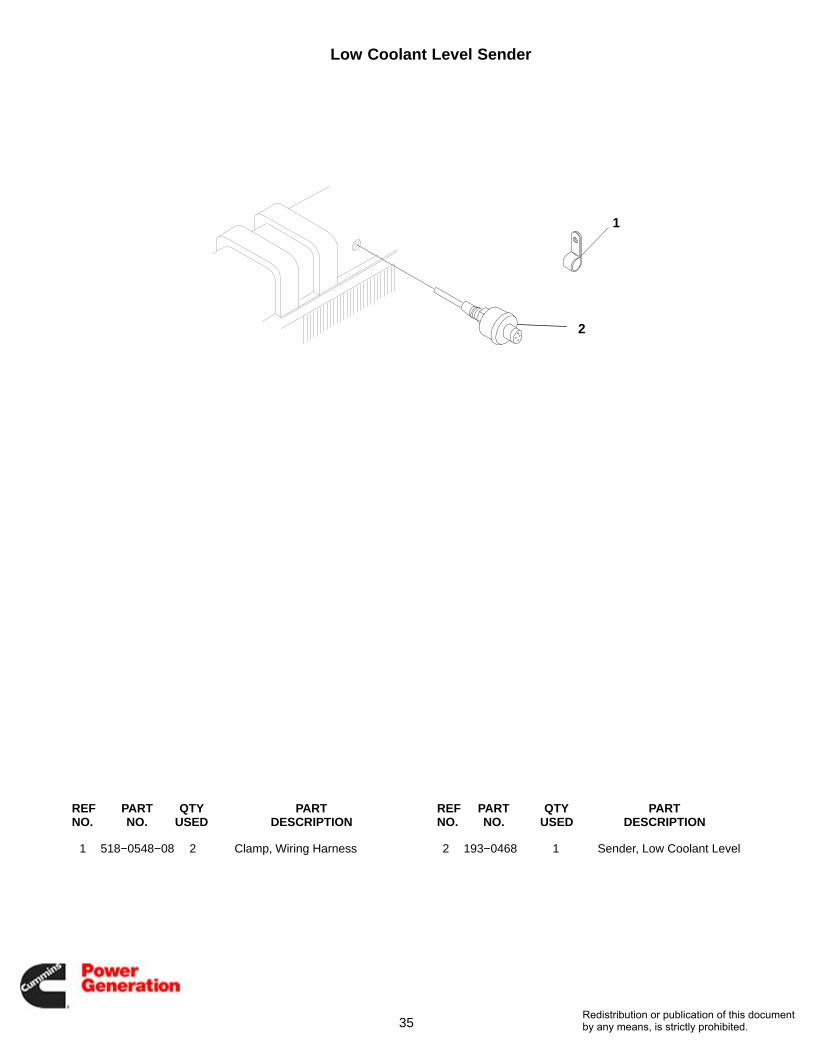
Low Coolant Level Sender
2
1
REF PART QTY PART REF PART QTY PARTNO. NO. USED DESCRIPTION NO. NO. USED DESCRIPTION
1 518−0548−08 2 Clamp, Wiring Harness 2 193−0468 1 Sender, Low Coolant Level
Redistribution or publication of this documentby any means, is strictly prohibited.

36
Radiator
1
2 3
4142
434
34
33
6
5
7
8
9
10
11
12
13
14
27
15
16
27
17
18
18
1949
35
35
35
30
20
21
27
28
43
27
22
23
24
25
29
29
27
26
31
31
3236
34
38
38
38
38
39
39
37
32
38
40
34
36
4445
46
47
48
50
51
52
53
Redistribution or publication of this documentby any means, is strictly prohibited.

37
Radiator
REF PART QTY PART REF PART QTY PARTNO. NO. USED DESCRIPTION NO. NO. USED DESCRIPTION
1 130−5444 1 Radiator (Includes RadiatorCap, Sight Glass andOverflow Hose)
130−5481 1 Cap, Radiator − 10 PSI130−5482 1 Sight Glass503−0276 − Hose, Overflow − Bulk
(Order by the Foot − 5 Feet Required)
2 130−3931 1 Spacer, Fan3 130−4534 1 Fan, Engine4 503−1811 1 Elbow, Radiator − 30°5 130−4378 1 Tube, Radiator − Inlet6 130−5445−02 1 Tube, Radiator − Outlet7 130−5447−01 1 Tube, Air − Outlet8 130−5446−01 1 Tube, Air − Intake9 130−5454−02 1 Guard, Radiator (Right Hand)
10 130−5455−02 1 Guard, Radiator (Left Hand)11 130−3932−01 1 Guard, Fan (Right Hand)12 130−3932−02 1 Guard, Fan (Left Hand)13 130−5449−02 1 Guard, Belt (Right Hand)14 130−5450−02 1 Guard, Belt (Left Hand)15 130−5451−02 1 Guard, Belt (Bottom)16 130−5452−02 1 Guard, Belt (Back)17 130−4075 1 Bracket, Guard18 402−0070 4 Dampener, Vibration19 130−4074 1 Bracket, Belt Guard20 130−5456−02 1 Bracket, Guard21 130−5457−02 4 Bracket, Guard − Radiator22 130−5459−02 2 Bracket, Tube23 155−3480 2 Clamp, Muffler24 130−5480 1 Cooler, Fuel25 402−0508 3 Isolator, Vibration26 130−5475−02 1 Bracket, Fuel Cooler27 821−6003−02 35 Screw, Hex Head (M8 x 1.25 x
20)
28 821−6007−02 10 Screw, Hex Head − StainlessSteel (M8 x 1.25 x 20)
29 870−0212 6 Nut Hex (1/4−20)30 821−5002−04 8 Screw, Hex Head (1/4−20 x
.63)31 502−1292 2 Connect, Tube − Turbo32 502−1384 2 Hose, Radiator33 503−1708 1 Hose, Radiator34 503−1872−04 8 Clamp, Hose35 821−5003−01 8 Screw, Hex Head (5/16−18 x
.50)36 503−1379−02 2 Hose, Radiator37 504−0176 1 Valve, Oil Drain38 503−1872−06 6 Clamp, Hose39 503−1872−07 2 Clamp, Hose40 098−7451 1 Label, Caution41 526−0026 6 Washer, Flat (3/8)42 800−0064 6 Screw, Cap − Hex Head
(3/8−16 x 4.50)43 821−5004−02 6 Screw, Cap (3/8−16 x .75)44 502−1043−05 1 Elbow, Adapter − Male45 505−0120 1 Elbow, Street − 90° (3/8)46 501−0551−01 1 Line, Flexible − Fuel47 505−0007 1 Bushing, Reducer (1/4 x 1/8)48 501−0216 1 Line, Flexible − Fuel49 800−2085 2 Screw, Cap − Hex Head (M10 x
1.5 x 20)50 505−0019 2 Bushing, Reducer (1/2 x 3/8)51 128−0117 1 Insulation, Foam52 821−6003−03 10 Screw, Hex Head (M8 x 1.25 x
20)53 518−0548−08 1 Clamp, Hose
Redistribution or publication of this documentby any means, is strictly prohibited.

38
Enclosure(F183)
1
2
33
45
6
6
7
8
9
10
11
12
13
14
15
1617
17
18
5
19
20
20
21
22
22
23
24
25
26
27
29
Redistribution or publication of this documentby any means, is strictly prohibited.

39
Enclosure(F183)
REF PART QTY PART REF PART QTY PARTNO. NO. USED DESCRIPTION NO. NO. USED DESCRIPTION
1 405−4110 2 Post, Housing − Center2 821−5004−02 10 Screw, Hex (3/8−16 x .75)3 821−5003−03 57 Screw, Hex (5/16−18 x .75)4 405−4111 2 Post, Housing − Rear5 405−4104 3 Grille6 405−4112 3 Post, Housing − Rear7 405−4107 2 Door − Side8 405−4106 1 Door − Control9 517−0245 1 Plug
10 405−4404 2 Door, Grille − Right11 405−4405 2 Door, Grille − Left12 406−0972−02 7 Latch, Door13 818−0231−02 28 Rivet, Pop14 405−3980 2 Stop, Housing Door15 128−0154 4 Insulation, Foam (58.0 x 6.75)16 128−0154−06 1 Insulation, Foam17 870−0257 74 Nut, Self-Locking − Flange
(5/16−18)
18 816−0098 62 Bolt, Carriage (5/16−18 x .62)19 520−0544 14 Stud, Generator Mounting20 870−0281 32 Nut, Self-Locking − Flange
(3/8−16)21 405−6950−02 1 Roof, Enclosure22 405−6943−02 4 Roof, Enclosure − Side23 405−6946−02 1 Roof, Enclosure − Rear24 405−6947−02 1 Roof, Enclosure − Front25 405−6949−02 2 Roof, Enclosure − Side26 130−5527−02 1 Bracket, Radiator27 821−6007−02 2 Screw, Hex Head − Stainless
Steel (M8 x 1.25 x 20)28 130−4848 − Insulation, Exhaust − Bulk
(Order by the Foot 17 FeetRequired) (Not Illustrated)
29 128−0154−01 1 Insulation, Foam (4.25 x 18)
Redistribution or publication of this documentby any means, is strictly prohibited.

40
EnclosureSteel
1
2
3
4
5
6
7
8
9
10
11
12
13
14
15
16
1717
18
19
20
21
23
24
25
26
27
28
29
3031
32
33
34
35
36
37
38
39
40
41
42
43
44
4546
46
4444
47
38
48
49
50
37
2251
52
53
54
55
5657
58
59
60
61
6263
64
65
66
67
68
Redistribution or publication of this documentby any means, is strictly prohibited.

41
EnclosureSteel
REF PART QTY PART REF PART QTY PARTNO. NO. USED DESCRIPTION NO. NO. USED DESCRIPTION
1 405−7501−02 1 Panel, Enclosure − RH Rear2 405−7500−02 1 Post, Enclosure − LH Rear3 155−4134−02 1 Shield, Heat − Exhaust4 405−7737−02 1 Panel, Enclosure − RH Front5 405−7738−02 1 Panel, Enclosure − LH Front6 405−7739−02 4 Post, Enclosure − Center7 405−7741−02 6 Crossmember, Panel − Upper8 405−7577−02 1 Stiffener, Enclosure9 405−7742−02 2 Stiffener, Roof
10 405−7740−02 6 Stiffener, Enclosure − Truss11 405−7735−04 1 Panel, Roof − LH12 405−7734−04 1 Panel, Roof − RH13 405−7736−02 1 Panel, Roof − Rear14 405−7743−02 1 Panel, Duct − Upper15 405−7744−02 1 Panel, Duct − Lower16 Door, Enclosure
405−7574−02 6 Without 150 MPH Wind Rating
405−7574−04 6 With 150 MPH Wind Rating17 405−7604−02 1 Crossmember, Panel − Rear18 406−0970−01 3 Hinge19 406−0970−02 3 Hinge20 Latch
406−0972−02 6 Without 150 MPH Wind Rating
406−0972−02 12 With 150 MPH Wind Rating21 406−1049−01 3 Catch, Door22 517−0364 60 Plug, Hole23 405−7745 1 * Retainer, Insulation − Roof24 405−7746 1 * Retainer, Insulation − Roof25 405−7616 2 * Retainer, Insulation − Side26 405−7617 4 * Retainer, Insulation − Post27 405−7618 6 * Retainer, Insulation − Door28 405−7620 1 * Retainer, Insulation − Post29 405−7637 1 * Retainer, Insulation − Post30 405−7626 1 * Insulation, Roof31 405−6000−08 4 * Insulation, Panel − Roof32 405−6000−09 6 * Insulation, Panel − Cross33 405−7628 6 * Insulation, Door34 405−6000−10 4 * Insulation, Panel − Post35 405−7630 2 * Insulation, Enclosure − Post36 405−6000−11 6 * Insulation, Panel, Door37 406−1049−02 3 Catch, Door38 821−6003−02 78 Screw, Hex Head (M8 x 1.25 x
20)39 870−2065−03 12 Nut, Hex − Flange
40 Screw, Hex Head (M8 x 1.25 x20)
821−6007−02 90 Without 150 MPH Wind Rating
821−6007−02 98 With 150 MPH Wind Rating41 818−1157 96 Rivet, Dome Head − Blind (1/4)42 Rivet, Pop
818−0231−02 64 Without 150 MPH Wind Rating
818−0231−02 88 With 150 MPH Wind Rating − Not Insulated
818−0231−02 144 With 150 MPH Wind Rating − Insulated
43 818−0231−06 72 * Rivet, Pop44 526−0249−01 40 Washer, Flat (7/16)45 800−2089 26 Screw, Cap − Hex Head (M10 x
1.5 x 40)46 850−2010 32 Washer, Lock − Split (M10)47 860−2009 14 Nut, Hex (M10 x 1.5)48 526−2106 12 Washer, Flat (M8)49 853−2006 6 * Washer, Lock − W/ET (M6)50 821−6002−03 6 * Screw, Hex Head (M6 x 1 x 16)51 405−7812−01 6 Seal, Door52 405−7812−02 6 Seal, Door53 405−7577−04 1 Stiffener, Enclosure54 406−0970−03 3 Hinge55 406−0970−04 3 Hinge56 405−7863−02 2 Edge, Drip − Enclosure57 821−6006−01 40 Screw, Hex Head (M6 x 1.0 x
16)58 800−6294 18 Screw, Hex − Flange Head (#8
x 5/8)59 406−0929 18 Clip, Panel60 405−7882 1 Gasket, Enclosure61 405−7883 2 Gasket, Enclosure62 405−7885−02 2 Cover, Enclosure63 405−7884−02 1 Cover, Enclosure64 508−1102 1 Grommet, Rubber65 405−7756−02 2 Bracket, Duct − Stiffener − With
150 MPH Wind Rating66 870−2055 4 Nut, Locking − With 150 MPH
Wind Rating67 508−1042−09 12 * Edging68 517−0350 1 Plug, Hole
* − Insulated Enclosures
Redistribution or publication of this documentby any means, is strictly prohibited.

42
EnclosureAluminum
1
2
3
4
5
6
7
8
9
10
11
13
14
15
16
1717
19
20
21
22
24
25
26
27
28
29
30
3132
33
34
35
36
37
40
42
43
44
46
47
48
49
5051
51
4949
52
42
53
54
55
40
2338
39
41
61
62
6364
65
66
6718
12
45
56 57
5859
Redistribution or publication of this documentby any means, is strictly prohibited.

43
EnclosureAluminum
REF PART QTY PART REF PART QTY PARTNO. NO. USED DESCRIPTION NO. NO. USED DESCRIPTION
1 405−7838 1 Panel, Enclosure − RH Rear2 405−7836 1 Post, Enclosure − LH Rear3 405−7835 1 Shield, Heat − Exhaust4 405−7847 1 Panel, Enclosure − RH Front5 405−7848 1 Panel, Enclosure − LH Front6 405−7849 4 Post, Enclosure − Center7 405−7851 6 Crossmember, Panel − Upper8 405−7577−02 2 Stiffener, Enclosure9 405−7742−02 2 Stiffener, Roof
10 405−7740−02 6 Stiffener, Enclosure − Truss11 405−7845−02 1 Panel, Roof − LH12 405−7844−02 1 Panel, Roof − RH13 405−7846 1 Panel, Roof − Rear14 405−7853 1 Panel, Duct − Upper15 405−7854 1 Panel, Duct − Lower16 405−7840 6 Door, Enclosure17 405−7843 1 Crossmember, Panel − Rear18 405−7855 2 Bracket, Duct − Stiffener19 406−0970−01 3 Hinge20 406−0970−02 3 Hinge21 406−0972−02 12 Latch22 406−1049−01 3 Catch, Door23 517−0364 60 Plug, Hole24 405−7745 1 * Retainer, Insulation − Roof25 405−7746 1 * Retainer, Insulation − Roof26 405−7616 2 * Retainer, Insulation − Side27 405−7617 4 * Retainer, Insulation − Post28 405−7618 6 * Retainer, Insulation − Door29 405−7620 1 * Retainer, Insulation − Post30 405−7637 1 * Retainer, Insulation − Post31 405−7626 1 * Insulation, Roof32 405−6000−08 4 * Insulation, Panel − Roof33 405−6000−09 6 * Insulation, Panel − Cross34 405−7628 6 * Insulation, Door35 405−6000−10 4 * Insulation, Panel − Post36 405−7630 2 * Insulation, Enclosure − Post37 405−6000−11 6 * Insulation, Panel, Door38 405−7812−01 6 Seal, Door
39 405−7812−02 6 Seal, Door40 406−1049−02 3 Catch, Door41 405−7842 4 Stiffener, Enclosure42 821−6003−02 78 Screw, Hex Head (M8 x 1.25 x
20)43 870−2065−03 12 Nut, Hex − Flange44 821−6007−02 98 Screw, Hex Head (M8 x 1.25 x
20)45 870−2055 4 Nut, Hex − Flange (M8 x 1.25)46 818−1157 96 Rivet, Dome Head − Blind (1/4)47 Rivet, Pop
818−0231−02 88 Not Insulated818−0231−02 144 Insulated
48 818−0231−06 72 * Rivet, Pop49 526−0249−01 34 Washer, Flat (7/16)50 800−2089 26 Screw, Cap − Hex Head (M10 x
1.5 x 40)51 850−2010 26 Washer, Lock − Split (M10)52 860−2009 8 Nut, Hex (M10 x 1.5)53 526−2106 12 Washer, Flat (M8)54 853−2006 6 * Washer, Lock − W/ET (M6)55 821−6002−03 6 * Screw, Hex Head (M6 x 1 x 16)56 405−7882 1 Gasket, Enclosure57 405−7883 1 Gasket, Enclosure58 405−7837 1 Cover, Enclosure59 405−7839 1 Cover, Enclosure60 405−7577−04 1 Stiffener, Enclosure61 406−0970−03 3 Hinge62 406−0970−04 3 Hinge63 405−7850 2 Edge, Drip − Enclosure64 821−6006−01 28 Screw, Hex Head (M6 x 1.0 x
16)65 800−6294 18 Screw, Hex − Flange Head (#8
x 5/8)66 405−7879 12 Gasket, Door67 406−0929 18 Clip, Panel
* − Insulated Enclosures
Redistribution or publication of this documentby any means, is strictly prohibited.
44
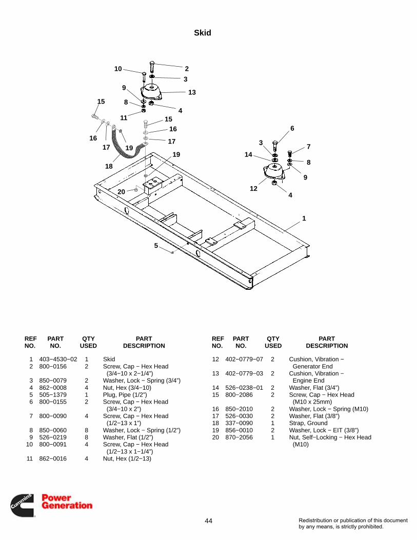
Skid
1
2
3
3
4
4
5
6
7
8
9
10
9
8
11
15
1617
18
19
1516
13
17
19 14
1220
REF PART QTY PART REF PART QTY PARTNO. NO. USED DESCRIPTION NO. NO. USED DESCRIPTION
1 403−4530−02 1 Skid2 800−0156 2 Screw, Cap − Hex Head
(3/4−10 x 2−1/4”)3 850−0079 2 Washer, Lock − Spring (3/4”)4 862−0008 4 Nut, Hex (3/4−10)5 505−1379 1 Plug, Pipe (1/2”)6 800−0155 2 Screw, Cap − Hex Head
(3/4−10 x 2”)7 800−0090 4 Screw, Cap − Hex Head
(1/2−13 x 1”)8 850−0060 8 Washer, Lock − Spring (1/2”)9 526−0219 8 Washer, Flat (1/2”)
10 800−0091 4 Screw, Cap − Hex Head(1/2−13 x 1−1/4”)
11 862−0016 4 Nut, Hex (1/2−13)
12 402−0779−07 2 Cushion, Vibration − Generator End
13 402−0779−03 2 Cushion, Vibration −Engine End
14 526−0238−01 2 Washer, Flat (3/4”)15 800−2086 2 Screw, Cap − Hex Head
(M10 x 25mm)16 850−2010 2 Washer, Lock − Spring (M10)17 526−0030 2 Washer, Flat (3/8”)18 337−0090 1 Strap, Ground19 856−0010 2 Washer, Lock − EIT (3/8”)20 870−2056 1 Nut, Self−Locking − Hex Head
(M10)
Redistribution or publication of this documentby any means, is strictly prohibited.
45
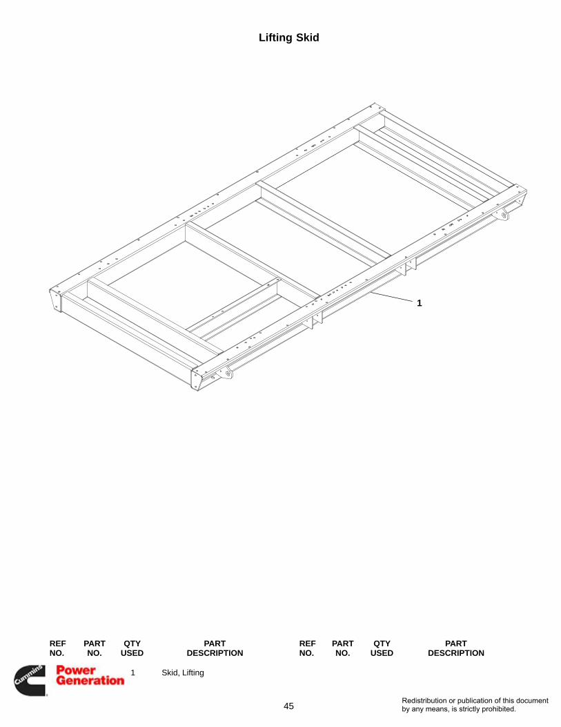
Lifting Skid
1
REF PART QTY PART REF PART QTY PARTNO. NO. USED DESCRIPTION NO. NO. USED DESCRIPTION
1 403−5034−02 1 Skid, Lifting
Redistribution or publication of this documentby any means, is strictly prohibited.

46
Mounting SystemSteel Enclosure
23
24
2728
30
32
35
36
1
2
5
67
7
8 9101112
1314
1516171819
2021
22
2526
29
31
33
24
34
Redistribution or publication of this documentby any means, is strictly prohibited.

47
Mounting SystemSteel Enclosure
REF PART QTY PART REF PART QTY PARTNO. NO. USED DESCRIPTION NO. NO. USED DESCRIPTION
1 405−7526−02 1 Duct, Air − Top2 405−7527−02 1 Duct, Air − Left3 405−7528−02 1 Duct, Air − Bottom (Not Shown)4 405−7529−02 1 Duct, Air − Right (Not Shown)5 405−5884−03 2 Seal, Radiator − Top, Botom6 405−5884−04 2 Seal, Radiator − Sides7 821−6003−02 12 Screw, Hex Head (M8 x 1.25 x
20)8 403−5111−02 3 Mount, Fuel Tank9 800−2114 12 Screw, Cap − Hex Head (M12 x
1.75 x 40)10 526−2140 24 Washer, Flat (M12)11 860−2010 12 Nut, Hex (M12 x 1.75)12 402−0816−01 6 Isolator, Vibration13 850−0070 8 Washer, Lock − Split (5/8)14 800−0132 8 Screw, Cap − Hex Head
(5/8−11 x 1.5)15 402−0820 4 Washer, Snubbing16 526−0027 4 Washer, Flat (3/4)17 403−3362 4 Washer, Bevel18 800−0167 4 Screw, Cap − Hex Head
(3/4−10 x 6.0)19 862−0008−01 4 Nut, Hex (3/4−10)
20 505−0019 1 Bushing, Reducer (1/2 x 3/8) −With Tank
21 505−0120 1 Elbow, Street − 90° (3/8) − WithTank
22 505−0050 1 Elbow, Street − 90° (1/2) − WithTank
23 503−2433−01 1 Hose, Breather (3/4 ID)24 502−1383 2 Union, Hose (3/4)25 337−0090−02 1 Strap, Electrical26 853−2012 2 Washer, Lock − W/ET (M12)27 503−2434−01 1 Hose, Drain (5/8)28 503−0131 1 Clamp, Hose29 502−1030 1 Connector, Hose − 90° (1/2 x
3/4)30 503−0189 2 Clamp, Hose31 503−2433−02 1 Hose, Breather (3/4 ID)32 405−7657−04 2 Gasket, Enclosure − With Tank33 502−0827 1 Hose, Barb (3/4 x 1/2)34 502−0876 1 Cap, Pipe (1/2) − Brass35 518−0704 1 Clamp, J36 800−0026 1 Screw, Cap − Hex Head
(5/16−18 x .75)
Redistribution or publication of this documentby any means, is strictly prohibited.
48
Mounting SystemAluminum Enclosure
123
45678
910
1112131415
1617
18
1920
20
21
2223
2425
26
27
28
29
3031
32
33
Redistribution or publication of this documentby any means, is strictly prohibited.

49
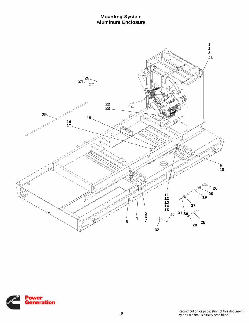
Mounting SystemAluminum Enclosure
REF PART QTY PART REF PART QTY PARTNO. NO. USED DESCRIPTION NO. NO. USED DESCRIPTION
1 Duct, Air405−7872 1 Top405−7873 1 Left Side405−7874 1 Bottom405−7875 1 Right Side
2 405−5884−03 2 Seal, Radiator − Top andBottom
3 405−5884−04 2 Seal, Radiator − Sides4 403−5111−02 2 Mount, Fuel Tank5 800−2114 12 Screw, Cap − Hex Head (M12 x
1.75 x 40)6 526−2140 24 Washer, Flat (M12)7 860−2010 12 Nut, Hex (M12 x 1.75)8 402−0816−01 4 Isolator, Vibration9 850−0070 8 Washer, Lock − Split (5/8)
10 800−0132 8 Screw, Cap − Hex Head(5/8−11 x 1.5)
11 402−0820 4 Washer, Snubbing12 526−0027 4 Washer, Flat (3/4)13 403−3362 4 Washer, Bevel14 800−0167 4 Screw, Cap − Hex Head
(3/4−10 x 6.0)15 862−0008−01 4 Nut, Hex − Heavy (3/4−10)16 505−0019 1 Bushing, Reducer (1/2 x 3/8) −
With Tank
17 505−0120 1 Elbow, Street − 90° (3/8) − WithTank
18 505−0050 1 Elbow, Street − 90° (1/2) − WithTank
19 503−2433−01 1 Hose, Breather (3/4 ID)20 502−1383 2 Union, Hose (3/4)21 821−6003−02 12 Screw, Hex Head (M8 x 1.25 x
20)22 337−0090−02 1 Strap, Electrical23 853−2012 2 Washer, Lock − W/ET (M12)24 503−2434−01 1 Hose, Drain (5/8)25 503−0131 1 Clamp, Hose26 502−1030 1 Connector, Hose − 90° (1/2 x
3/4 Hose)27 503−0189 2 Clamp, Hose28 503−2433−02 1 Hose, Breather (3/4 ID)29 405−7657−04 2 Gasket, Enclosure − With Tank30 502−0827 1 Hose, Barb (3/4 x 1/2)31 502−0876 1 Cap, Pipe (1/2)32 518−0704 1 Clamp, J33 800−0026 1 Screw, Cap − Hex Head
(5/16−18 x .75)
Redistribution or publication of this documentby any means, is strictly prohibited.

50
Electric Starter
1
22 3
4
5
678
910
REF PART QTY PART REF PART QTY PARTNO. NO. USED DESCRIPTION NO. NO. USED DESCRIPTION
1 191−2341 1 Starter (24VDC)2 416−1092 2 Cable, Battery3 416−1097 1 Cable, Battery − Jumper4 416−0680 1 Cable, Battery − Starter to
Ground5 332−0941 2 Tie, Cable
6 856−0010 1 Washer, Lock − W/EIT (3/8”)7 850−2010 1 Washer, Lock − Spring (M10)8 800−2085 1 Screw, Cap − Hex Head
(M10 x 20mm)9 416−1019 1 Battery, Boot − Red
10 416−1084 1 Starter, Boot − Red
Redistribution or publication of this documentby any means, is strictly prohibited.

51
Entrance Box
2
1
3
9
3 5
10
8
7
6
3
3
3
4
1112
13
14
15
REF PART QTY PART REF PART QTY PARTNO. NO. USED DESCRIPTION NO. NO. USED DESCRIPTION
1 319−3169 1 Box, Entrance2 319−1915 1 Panel (Top)3 821−6002−03 44 Screw, Self−Locking − Hex
Washer Head (M6 x 16mm)4 508−1092 − Edging − Bulk (Order By The
Foot − 2 Feet Required)5 870−0504 16 Nut, Self−Retaining (M6)6 319−1916 1 Cover7 319−3284 1 Brace, Cover8 319−3251 1 Brace, Cover
9 821−2035 2 Screw, Self−Locking − HexWasher Head (M6 x 25mm)
10 319−3183 1 Panel (Bottom)11 332−2001 1 Lug, Solderless12 856−0010 1 Washer, Lock − EIT (3/8”)13 526−2120 1 Washer, Flat (M10)
20mm)14 850−2010 1 Washer, Lock − Spring (M10)15 800−2088 1 Screw, Cap − Hex Head
(M10 x 1.5 x 35mm)
Redistribution or publication of this documentby any means, is strictly prohibited.

52
Control Housing
1
2
3
4
5
67
7
7
7
7
7
7
7
7
7
8
910
10
11
12
13
1314
14
1315
16
16
1718
19
2020
21
22
22
22
22
23
23
23
23
24
14
29
2526
27
27
28
30
7
23
30
Redistribution or publication of this documentby any means, is strictly prohibited.

53
Control Housing
REF PART QTY PART REF PART QTY PARTNO. NO. USED DESCRIPTION NO. NO. USED DESCRIPTION
1 319−3270−01 1 Panel − Bottom2 821−6004−01 6 Screw, Self−Locking − Hex
Washer Head (M10 x 20mm)3 319−3287−01 Panel − Right Side4 508−1090 2 Grommet, Rubber
(Fits 3−1/4” Hole)5 319−4453−02 Panel − Front6 301−9512 1 Cover, Top7 821−6002−03 69 Screw, Self−Locking − Hex
Washer Head (M6 x 16mm)8 319−3287−02 1 Panel − Left Side9 856−0006 2 Washer, Lock − W/EIT (1/4”)
10 405−7249−02 2 Rail, Enclosure − Support11 405−7254−02 1 Rail, Enclosure − Front12 319−2768 1 Grille13 870−2054 8 Nut, Locking − Hex Flange Head
(M6 x 1.0)14 518−0548−02 3 Clamp, Hose15 301−9629 2 Cover, Side − Lower
16 319−3255 2 Bracket, Mounting17 800−2111 6 Screw, Cap − Hex Head
(M12 x 25mm)18 850−2012 6 Washer, Lock − Spring (M12)19 800−2114 1 Screw, Cap − Hex Head
(M12 x 40mm)20 319−3257 2 Panel, Support21 319−1345 1 Bracket, Panel22 821−6003−02 7 Screw, Self−Locking − Hex
Washer Head (M8 x 1.25 x 20)23 870−2055 7 Nut, Locking − Hex Head (M8 x
1.25)24 319−3278 2 Wrapper, Control Box25 518−0548−24 1 Clamp, Retainer26 526−2100 1 Washer, Flat (M8)27 517−0131 3 Plug, Hole (Fits 3/8” Hole)28 402−0729 4 Isolator, Vibration29 517−0136 2 Plug, Hole (Fits 3/4” Hole)30 517−0135 1 Plug, Hole (Fits 5/8” Hole)
Redistribution or publication of this documentby any means, is strictly prohibited.
54
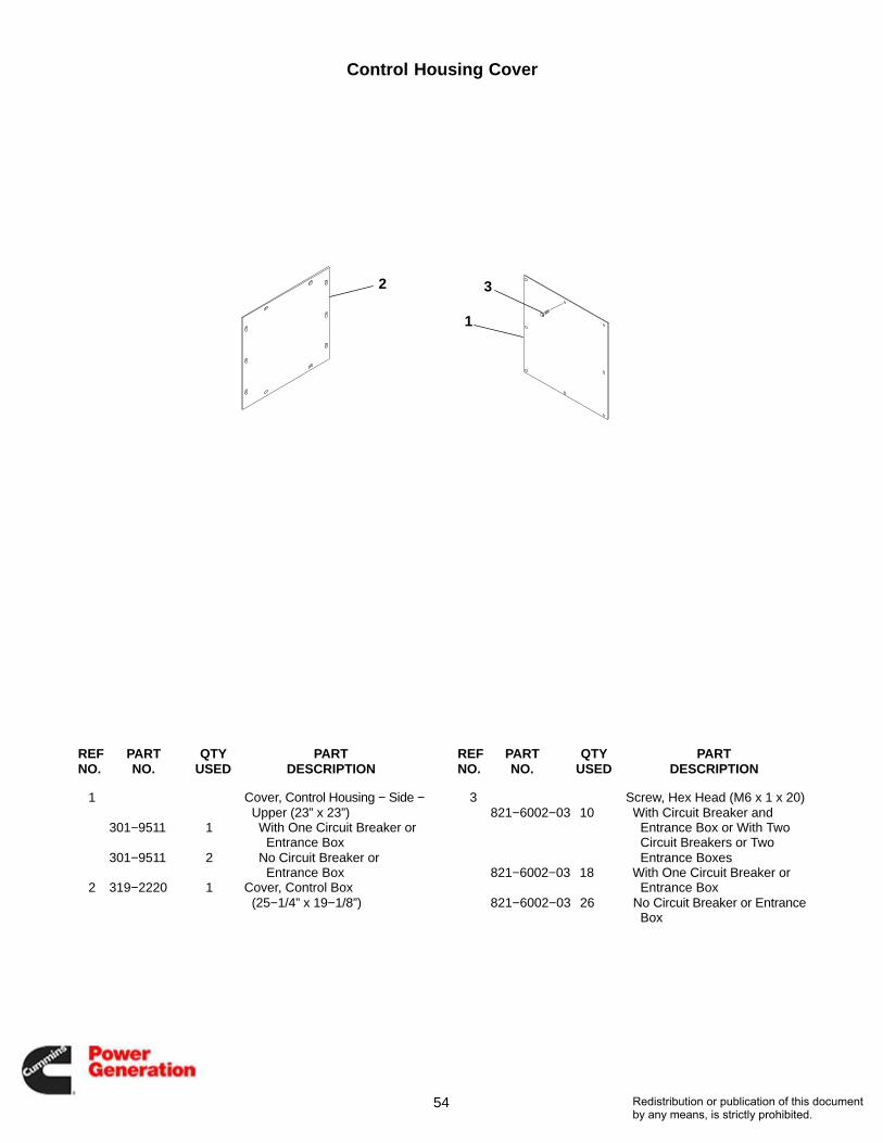
Control Housing Cover
3
1
2
REF PART QTY PART REF PART QTY PARTNO. NO. USED DESCRIPTION NO. NO. USED DESCRIPTION
1 Cover, Control Housing − Side −Upper (23” x 23”)
301−9511 1 With One Circuit Breaker or Entrance Box
301−9511 2 No Circuit Breaker or Entrance Box
2 319−2220 1 Cover, Control Box(25−1/4” x 19−1/8”)
3 Screw, Hex Head (M6 x 1 x 20)821−6002−03 10 With Circuit Breaker and
Entrance Box or With Two Circuit Breakers or Two Entrance Boxes
821−6002−03 18 With One Circuit Breaker or Entrance Box
821−6002−03 26 No Circuit Breaker or EntranceBox
Redistribution or publication of this documentby any means, is strictly prohibited.

55
Control Assembly
1
2
3
5
4
5
6
6
7
8
9
4
10
11
REF PART QTY PART REF PART QTY PARTNO. NO. USED DESCRIPTION NO. NO. USED DESCRIPTION
1 319−5025−02 1 Cover, Control2 319−5026−02 1 Cover, Control3 319−5027−02 1 Cover, Control4 821−6002−03 23 Screw, Hex Head (M6 x 1 x 16)5 856−0010 2 Washer, Lock − W/EIT (3/8)6 821−6003−01 3 Screw, Hex Head (M8 x 1.25 x
16)
7 862−0001 2 Nut, Hex (1/4−20)8 850−0045 4 Washer, Lock − Split (5/16)9 821−0014 4 Screw, Locking − Hex Head
(5/16−18 x 1/2)10 405−7666−02 1 Cover, Access11 508−1188 − Edging − Bulk (Order by the
Foot − 5 Feet Required)
Redistribution or publication of this documentby any means, is strictly prohibited.
56
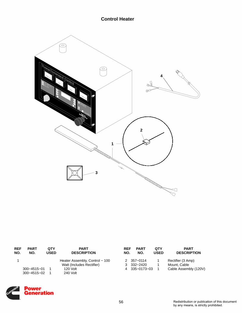
Control Heater
3
1
2
4
REF PART QTY PART REF PART QTY PARTNO. NO. USED DESCRIPTION NO. NO. USED DESCRIPTION
1 Heater Assembly, Control − 100Watt (Includes Rectifier)
300−4515−01 1 120 Volt300−4515−02 1 240 Volt
2 357−0114 1 Rectifier (3 Amp)3 332−2420 1 Mount, Cable4 335−0173−03 1 Cable Assembly (120V)
Redistribution or publication of this documentby any means, is strictly prohibited.

57
This Page Intentionally Left Blank.
Redistribution or publication of this documentby any means, is strictly prohibited.

58
Control Door
12
1
9
10
1314
10
11
98
76
53
4
152
16
14
17
Redistribution or publication of this documentby any means, is strictly prohibited.

59
Control Door
REF PART QTY PART REF PART QTY PARTNO. NO. USED DESCRIPTION NO. NO. USED DESCRIPTION
1 Door Assembly (IncludesMembrane, Display Windowand Parts Marked *)
English300−4608−01 1 Single Set300−4608−02 1 Paralleling Sets
Spanish300−4610−01 1 Single Set300−4610−02 1 Paralleling Sets
2 332−3262 4 Mount, Tie − Cable3 Board, Printed Circuit − Display
(A35)300−4481 1 Single Set300−4286 1 Paralleling Sets
4 815−0550 5 Screw, Machine − Pan Head −Cross Recessed W/ET(#6−32 x 3/8”)
5 302−2012 1 Wattmeter (0−125 %) (M24)6 302−2010 1 Meter, Frequency (45−65 Hz)
(M23)7 Voltmeter, AC (M21)
302−2009−01 1 0−300/0−600 Volt302−2009−02 1 0−750 Volt302−2009−03 1 0−5250 Volt302−2009−04 1 0−15 kV
8 302−2011 1 Ammeter (0−125 %) (M22)
9 308−0998 1 Switch, Selector − Run/Off/Auto(Knob Operated Switch)(S12)
308−1045 1 Switch, Selector (KeyOperated) (Includes 2Keys) (Converts308−0998 Knob OperatedSelector Switch To A KeyOperated Selector Switch)(Not Illustrated)
308−1046 2 Key, Replacement (NotIllustrated)
10 308−0999 1 Switch, Pushbutton −Emergency Stop (S13)
11 526−0257 8 Washer, Flat (#4)12 338−2937 1 Harness, Wiring − Control Door
(Includes Selector Switch andEmergency Stop Switch)
13 526−0417 2 * Washer, Flat (#4)14 870−1220 10 * Nut, Hex − W/ET (#4−40)15 338−2934 1 Cable, Ribbon (10−1/2”) (A32
to A35)16 332−1445 4 Tie, Cable17 406−0761−03 2 * Fastener, Door
* − Parts Included in Door Assembly
Redistribution or publication of this documentby any means, is strictly prohibited.

60
Control Box
13
2
6
16
4
14
15
5
108
9
7
18
17
12
11 13
19
20
21
22
2323
24
26
27
28
Redistribution or publication of this documentby any means, is strictly prohibited.
61
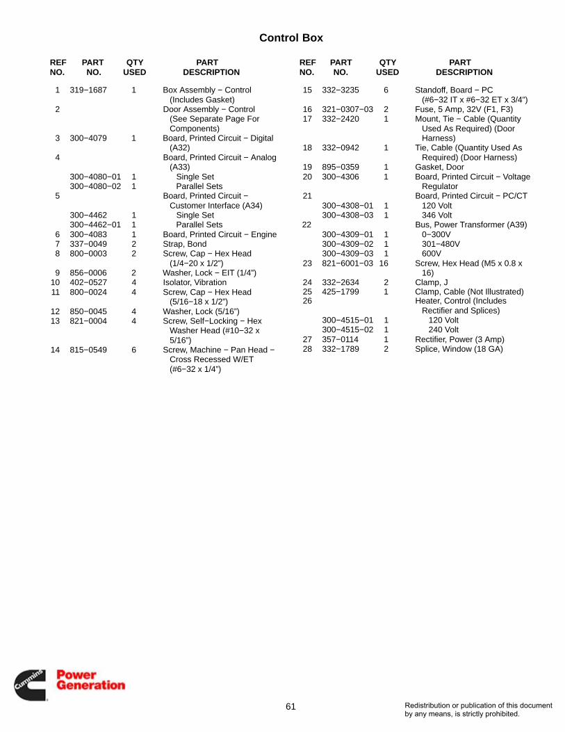
Control Box
REF PART QTY PART REF PART QTY PARTNO. NO. USED DESCRIPTION NO. NO. USED DESCRIPTION
1 319−1687 1 Box Assembly − Control (Includes Gasket)
2 Door Assembly − Control (See Separate Page ForComponents)
3 300−4079 1 Board, Printed Circuit − Digital(A32)
4 Board, Printed Circuit − Analog(A33)
300−4080−01 1 Single Set300−4080−02 1 Parallel Sets
5 Board, Printed Circuit −Customer Interface (A34)
300−4462 1 Single Set300−4462−01 1 Parallel Sets
6 300−4083 1 Board, Printed Circuit − Engine7 337−0049 2 Strap, Bond8 800−0003 2 Screw, Cap − Hex Head
(1/4−20 x 1/2”)9 856−0006 2 Washer, Lock − EIT (1/4”)
10 402−0527 4 Isolator, Vibration11 800−0024 4 Screw, Cap − Hex Head
(5/16−18 x 1/2”)12 850−0045 4 Washer, Lock (5/16”)13 821−0004 4 Screw, Self−Locking − Hex
Washer Head (#10−32 x5/16”)
14 815−0549 6 Screw, Machine − Pan Head −Cross Recessed W/ET(#6−32 x 1/4”)
15 332−3235 6 Standoff, Board − PC (#6−32 IT x #6−32 ET x 3/4”)
16 321−0307−03 2 Fuse, 5 Amp, 32V (F1, F3)17 332−2420 1 Mount, Tie − Cable (Quantity
Used As Required) (DoorHarness)
18 332−0942 1 Tie, Cable (Quantity Used AsRequired) (Door Harness)
19 895−0359 1 Gasket, Door20 300−4306 1 Board, Printed Circuit − Voltage
Regulator21 Board, Printed Circuit − PC/CT
300−4308−01 1 120 Volt300−4308−03 1 346 Volt
22 Bus, Power Transformer (A39)300−4309−01 1 0−300V300−4309−02 1 301−480V300−4309−03 1 600V
23 821−6001−03 16 Screw, Hex Head (M5 x 0.8 x16)
24 332−2634 2 Clamp, J25 425−1799 1 Clamp, Cable (Not Illustrated)26 Heater, Control (Includes
Rectifier and Splices)300−4515−01 1 120 Volt300−4515−02 1 240 Volt
27 357−0114 1 Rectifier, Power (3 Amp)28 332−1789 2 Splice, Window (18 GA)
Redistribution or publication of this documentby any means, is strictly prohibited.

62
Generator Heater
4
1516
2
17
1110 13
4
12
568
7
19
143
9
1
Redistribution or publication of this documentby any means, is strictly prohibited.

63
Generator Heater
REF PART QTY PART REF PART QTY PARTNO. NO. USED DESCRIPTION NO. NO. USED DESCRIPTION
1 333−0438−03 2 Cartridge, Heater − 120 Volt2 232−3850 1 Bracket, Mounting − Heater3 332−3024−14 4 Clamp, Loop4 822−3075 6 Screw, Machine − Slotted Pan
Head (M4 x 16mm)5 850−2004 2 Washer, Lock − Spring (M4)6 860−2005 2 Nut, Hex (M4)7 850−2005 2 Washer, Lock − Spring (M5)8 860−2006 2 Nut, Hex (M5)9 800−2008 2 Screw, Cap − Hex Head (M5 x
16mm)10 850−2003 1 Washer, Lock − Spring (M3)11 822−3047 1 Screw, Machine − Pan Head
(M3 x 20mm)
12 508−0228 1 Grommet13 332−3023 1 Block, Terminal14 898−1254−25 1 Sleeving − Heater Leads (59”)15 330−0141−03 1 Cover, Box16 330−0141−04 1 Gasket, Cover17 330−0142 1 Box, Terminal18 331−0027 1 Connector, Romex (1/2”) (Not
Illustrated)19 335−0173−04 1 Cable Assembly20 331−0027 1 Connector, Romex
(Not Illustrated)
Redistribution or publication of this documentby any means, is strictly prohibited.
64
Generator
60
59
49
48
11
14
10
151415
161718
5919
1343
44
50
51
52
4
8
3
32
3930
761
631
36 3837
40
41
89
56
6247
58 57
45
46
5355 54
21
33 3435
22
2827
29
262524
20
13
1
2
42
12
23
Redistribution or publication of this documentby any means, is strictly prohibited.

65
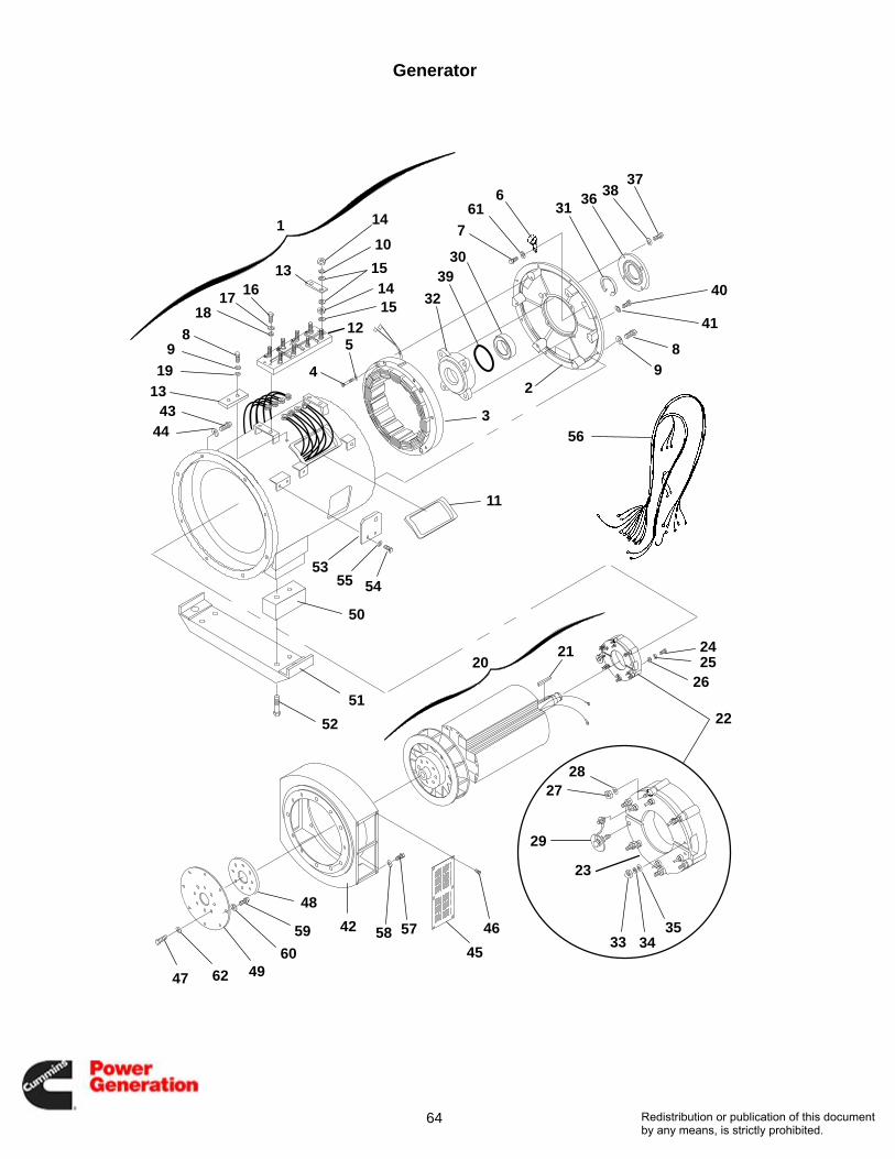
Generator
REF PART QTY PART REF PART QTY PARTNO. NO. USED DESCRIPTION NO. NO. USED DESCRIPTION
1 − 1 Stator Assembly, Generator −Complete (See SeparatePage For Part Numbers)(Includes Parts Marked *)
2 211−0431 1 *Bell, End3 220−4248 1 *Stator, Exciter4 800−2066 6 *Screw, Cap − Hex Head
(M8 x 65mm)5 850−2008 6 *Washer, Lock − Spring (M8)6 425−1799 1 *Clamp, Cable7 800−2004 1 *Screw, Cap − Hex Head
(M5 x 12mm)8 800−3017−39 9 *Screw, Cap − Hex Head9 850−0114−55 9 *Washer, Lock − Spring (M10)
10 850−2012 8 *Washer, Lock − Spring (M12)11 508−0306 2 *Grommet12 232−3482 1 *Panel, Terminal13 332−3009 4 *Link, Terminal14 860−2010 16 *Nut, Hex (M12)15 526−2140 24 *Washer, Flat (M12)16 800−2061 4 *Screw, Cap − Hex Head
(M8 x 40mm)17 850−2008 4 *Washer, Lock − Spring (M8)18 526−2100 4 *Washer, Flat (M8)19 526−2120 1 *Washer, Flat (M10)20 − 1 Rotor Assembly, Generator −
Complete (See SeparatePage For Part Numbers)(Includes Parts Marked #)
21 515−0300−01 1 #Key22 201−3460 1 #Rotor Assembly, Exciter
(Includes Parts Marked +)23 357−0093 1 #+Rectifier Assembly (Includes
Diodes and Varistor)24 800−2042 4 #+Screw, Cap − Hex Head
4 (M6 x 60mm)25 850−2006 4 #+Washer, Lock − Spring (M6)26 526−2080 4 #+Washer, Flat (M6)27 870−2064−02 6 #+Nut, Hex (M5)28 526−2060 6 #+Washer, Flat (M5)29 249−0797 1 Kit, Diode (Includes Varistor
And All Diodes)30 510−0168 1 #Bearing, Ball31 518−0018 1 #Ring, Retaining32 232−3518−01 1 #Housing, Bearing33 860−2006 2 #Nut, Hex (M5)
34 850−2005 2 #Washer, Lock − Spring (M5)35 526−2060 2 #Washer, Flat (M5)36 232−3981−01 1 #Cover, Bearing Housing37 800−2087 4 #Screw, Cap − Hex Head
(M10 x 30mm)38 850−2010 4 #Washer, Lock − Spring (M10)39 509−0266−03 1 #O-Ring40 800−2091 4 Screw, Cap − Hex Head
(M10 x 50mm)41 850−2010 4 Washer, Lock − Spring (M10)42 231−0322 1 Adapter, Generator43 Screw
800−3017−56 6 Cap − Hex Head(M12 x 40mm)
725−1103 2 Socket Head (M12 x 40mm)(Bottom Holes)
44 850−0114−56 8 Washer, Lock − Spring (M12)45 234−0889 2 Guard, Fan46 821−6001−02 12 Screw, Self-Locking − Hex
Washer Head (M5 x 12mm)47 720−1146 8 Screw, Cap − Hex Head
(M20 x 60mm)48 232−3520−01 1 Spacer, Drive Disc (3/8” Thk)49 232−3522 4 Disc, Drive50 232−3524 2 Spacer, Generator Foot51 232−3966 1 Foot, Generator52 800−2244 4 Screw, Cap − Hex Head
(M24 x 80mm)53 232−3523 2 Bracket, Generator Lifting54 800−3017−55 4 Screw, Cap − Hex Head
(M12 x 35mm)55 850−0114−56 4 Washer, Lock − Spring (M12)56 338−3348 1 Harness, Wiring57 800−0074 12 Screw, Cap − Hex Head
(7/16−14 x 1−3/4”)58 850−0055 12 Washer, Lock − Spring (7/16”)59 805−0032 8 Bolt, Place (1/2−13 x 1−1/4”)60 526−0035 8 Washer, Flat (1/2”)61 850−2005 1 *Washer, Lock − Spring (M5)62 526−0450 2 Washer, Flat
* − Parts Included In Generator Stator Assemblies# − Parts Included In Generator Rotor Assemblies+ − Parts Included In Exciter Rotor Assemblies
Redistribution or publication of this documentby any means, is strictly prohibited.

66
Generator Rotor and Stator Part Numbers
GeneratorIdentificationNumber
Service replacement part numbers for the main generator stator and rotor can be determined by locating the CumminsPower Generation 249−XXXX−XX generator identification number. This number is stamped on the engine end of the mainstator adapter ring in the area shown in the above illustration. Find the corresponding number in the chart below for thestator and rotor replacement part numbers and also to determine the generator model number. For COMPLETE generatorreplacement use the 249−XXXX−XX Cummins Power Generation identification number.
Component parts that are included with the main stator and rotor are listed on the “Generator” pages of this catalog.
Cummins PowerGeneration
IdentificationNumber
GeneratorModel
Stator AssemblyPart Number
Rotor AssemblyPart Number
249−5080−02 HC4 220−4468−01 201−3459−01
249−5080−03 HC4 220−4468−02 201−3459−02
249−5080−04 HC4 220−4468−03 201−3459−03
249−5080−05 HC4 220−4468−04 201−3459−04
249−5081−02 HC4 220−4468−07 201−3459−01
249−5081−03 HC4 220−4468−08 201−3459−02
249−5081−04 HC4 220−4468−09 201−3459−03
249−5081−05 HC4 220−4468−10 201−3459−04
Redistribution or publication of this documentby any means, is strictly prohibited.
67
Rail Mount
1
2
3
4 56
7
8
9
10
11
12
13
14
15
16
17
18
19
20
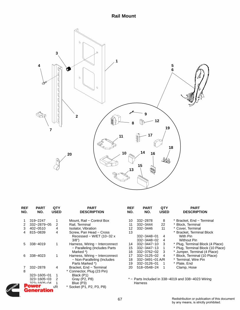
REF PART QTY PART REF PART QTY PARTNO. NO. USED DESCRIPTION NO. NO. USED DESCRIPTION
1 319−2247 1 Mount, Rail − Control Box2 332−2879−05 2 Rail, Terminal3 402−0510 4 Isolator, Vibration4 815−0839 4 Screw, Pan Head − Cross
Recessed − W/ET (10−32 x3/8”)
5 338−4019 1 Harness, Wiring − Interconnect− Paralleling (Includes PartsMarked *)
6 338−4023 1 Harness, Wiring − Interconnect− Non-Paralleling (IncludesParts Marked *)
7 332−2878 4 Bracket, End − Terminal8 * Connector, Plug (23 Pin)
323−1605−01 1 Black (P1)323−1605−03 2 Gray (P2, P8)323−1605−04 1 Blue (P3)
9 323−1614−01 A/R * Socket (P1, P2, P3, P8)
10 332−2878 8 * Bracket, End − Terminal11 332−3444 22 * Block, Terminal12 332−3446 11 * Cover, Terminal13 * Bracket, Terminal Block
332−3448−01 4 With Pin332−3448−02 4 Without Pin
14 332−3447−10 3 * Plug, Terminal Block (4 Place)15 332−3447−13 1 * Plug, Terminal Block (10 Place)16 332−3762−02 3 * Jumper, Terminal (4 Place)17 332−3125−02 4 * Block, Terminal (10 Place)18 332−3491−01 A/R * Terminal, Wire Pin19 332−3126−01 1 * Plate, End20 518−0548−24 1 Clamp, Hose
* − Parts Included in 338−4019 and 338−4023 Wiring Harness
Redistribution or publication of this documentby any means, is strictly prohibited.

68
Customer Relay
1
2
3
REF PART QTY PART REF PART QTY PARTNO. NO. USED DESCRIPTION NO. NO. USED DESCRIPTION
1 Relay307−1056−01 1 Alarm Relay307−1056−01 3 Run Relays
2 Socket, Relay323−1410−01 1 Alarm Relay323−1410−01 3 Run Relays
3 323−1411−01 1 Clip, Socket Mounting
Redistribution or publication of this documentby any means, is strictly prohibited.

69
Ground Fault Relay
1
2
3
4
5
6
7
6
7
8
9
10
REF PART QTY PART REF PART QTY PARTNO. NO. USED DESCRIPTION NO. NO. USED DESCRIPTION
1 307−3003−01 1 Relay, Ground Fault2 301−6987 1 Bracket, Watts Transducer3 821−0017 2 Screw, Locking (5/16−18 x 1/2)4 870−0257 2 Nut, Self-Locking (5/16−18)5 402−0354 4 Mount, Shock
6 853−0005 8 Washer, Lock − W/ET (#8)7 870−0221 8 Nut, Hex − W/ET (#8−32)8 338−3232 1 Harness, Relay9 332−2420 2 Mount, Cable Tie
10 319−5038−02 1 Plate, Mounting − Relay
Redistribution or publication of this documentby any means, is strictly prohibited.

70
Genset Communications ModuleFT-10
12
REF PART QTY PART REF PART QTY PARTNO. NO. USED DESCRIPTION NO. NO. USED DESCRIPTION
1 327−1301 1 Board, Printed Circuit − GensetCommunications Module
2 332−3235 4 Standoff, Printed Circuit Board(#6−32 x .75)
Redistribution or publication of this documentby any means, is strictly prohibited.

71
Louver AssemblySteel Air Inlet
1 23
4
4
5
6
7
8
910
11
REF PART QTY PART REF PART QTY PARTNO. NO. USED DESCRIPTION NO. NO. USED DESCRIPTION
1 Louver Assembly (SeeSeparate Page forComponents)
405−7631−01 1 Weather Louvers405−7631−02 1 Acoustic Louvers
2 405−7569 1 Grill, Enclosure − Mesh3 405−7633 1 Louver Assembly − Rain Hood
(See Separate Page forComponents)
4 Screw, Hex Head (M8 x 1.25 x20)
821−6007−02 23 Without Rain Hood821−6007−02 50 With Rain Hood
5 821−6003−02 20 Screw, Hex Head (M8 x 1.25 x20)
6 405−7606−02 4 Bracket, Grill7 Louver − Damper
405−7539−01 1 Spring Open − AC405−7539−02 1 Spring Closed − DC
8 406−0929 10 Clip, Panel − With Grill9 338−4295−01 1 Harness, Control
10 338−4295−03 1 Harness, Motor11 405−7754 1 Actuator, Louver (24V)
Redistribution or publication of this documentby any means, is strictly prohibited.

72
Louver AssemblyAluminum Air Inlet
1 23
4
4
5
6
7
8
910
11
REF PART QTY PART REF PART QTY PARTNO. NO. USED DESCRIPTION NO. NO. USED DESCRIPTION
1 Louver Assembly (SeeSeparate Page forComponents)
405−7720−01 1 Weather Louvers405−7720−02 1 Acoustic Louvers
2 405−7569 1 Grill, Enclosure − Mesh3 405−7726 1 Louver Assembly − Rain Hood
(See Separate Page forComponents)
4 Screw, Hex Head (M8 x 1.25 x20)
821−6007−02 27 Without Rain Hood821−6007−02 54 With Rain Hood
5 821−6003−02 20 Screw, Hex Head (M8 x 1.25 x20)
6 405−7728 4 Bracket, Grill7 Louver − Damper
405−7539−01 1 Spring Open − AC405−7539−02 1 Spring Closed − DC
8 406−0929 10 Clip, Panel − With Grill9 338−4295−01 1 Harness, Control
10 338−4295−03 1 Harness, Motor11 405−7754 1 Actuator, Louver (24V)
Redistribution or publication of this documentby any means, is strictly prohibited.

73
Louver AssemblySteel Weather and Acoustic
1
2
3 4
5 6
7
7
8
8
5
10
911
REF PART QTY PART REF PART QTY PARTNO. NO. USED DESCRIPTION NO. NO. USED DESCRIPTION
1 405−7534−02 5 Louver − Upper2 405−7553−02 1 Panel, Duct − Right3 405−7557−02 1 Louver − Bottom4 405−7554−02 1 Panel, Duct − Left5 405−7558−02 2 Bracket, Duct6 405−7534−04 1 Louver − Upper7 821−6007−02 17 Screw, Hex Head (M8 x 1.25 x
20)
8 Rivet, Pop818−0231−01 28 With Weather Louver818−0231−01 112 With Acoustic Louver
9 405−7535 6 Louver − Acoustic10 405−6000−15 6 Insulation, Panel − With
Acoustic Louver11 405−7755−02 1 Panel, Duct (Filler)
Redistribution or publication of this documentby any means, is strictly prohibited.

74
Louver AssemblyAluminum Weather and Acoustic
1
2
3 4
5 6
7
7
8
8
5
10
911
REF PART QTY PART REF PART QTY PARTNO. NO. USED DESCRIPTION NO. NO. USED DESCRIPTION
1 405−7721−01 5 Louver − Upper2 405−7722 1 Panel, Duct − Right3 405−7724 1 Louver − Bottom4 405−7723 1 Panel, Duct − Left5 405−7725 2 Bracket, Duct6 405−7721−02 1 Louver − Upper7 821−6007−02 17 Screw, Hex Head (M8 x 1.25 x
20)
8 Rivet, Pop818−0231−01 28 With Weather Louver818−0231−01 112 With Acoustic Louver
9 405−7535 6 Louver − Acoustic10 405−6000−15 6 Insulation, Panel − With
Acoustic Louver11 405−7800 1 Panel, Duct (Filler)
Redistribution or publication of this documentby any means, is strictly prohibited.
75
Louver AssemblySteel Rain Hood
12
3
4
4
5
6
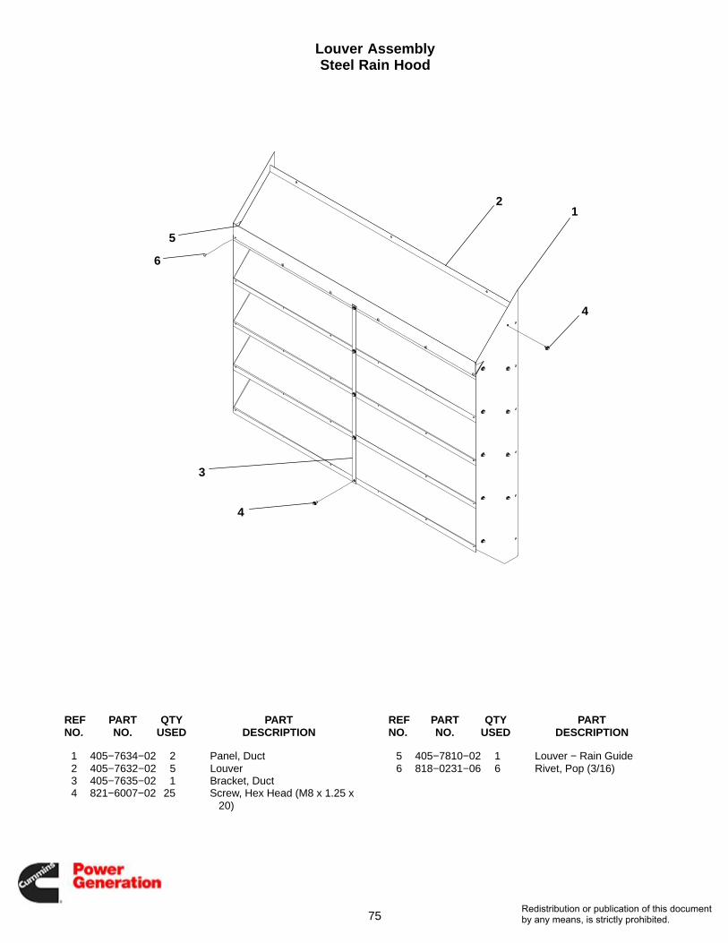
REF PART QTY PART REF PART QTY PARTNO. NO. USED DESCRIPTION NO. NO. USED DESCRIPTION
1 405−7634−02 2 Panel, Duct2 405−7632−02 5 Louver3 405−7635−02 1 Bracket, Duct4 821−6007−02 25 Screw, Hex Head (M8 x 1.25 x
20)
5 405−7810−02 1 Louver − Rain Guide6 818−0231−06 6 Rivet, Pop (3/16)
Redistribution or publication of this documentby any means, is strictly prohibited.

76
Louver AssemblyAluminum Rain Hood
12
3
4
4
5
6
REF PART QTY PART REF PART QTY PARTNO. NO. USED DESCRIPTION NO. NO. USED DESCRIPTION
1 405−7730 2 Panel, Duct2 405−7727 5 Louver3 405−7729 1 Bracket, Duct4 821−6007−02 25 Screw, Hex Head (M8 x 1.25 x
20)
5 405−7825 1 Louver − Rain Guide6 818−0231−02 6 Rivet, Pop
Redistribution or publication of this documentby any means, is strictly prohibited.
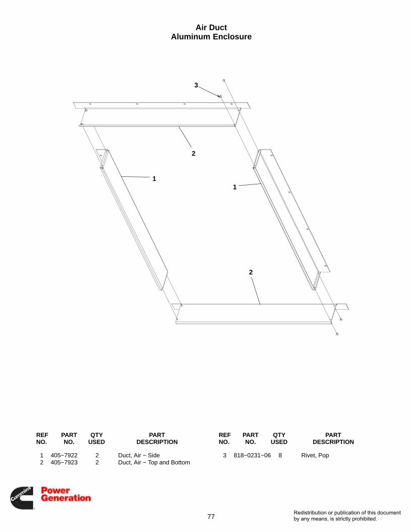
77
Air DuctAluminum Enclosure
11
2
2
3
REF PART QTY PART REF PART QTY PARTNO. NO. USED DESCRIPTION NO. NO. USED DESCRIPTION
1 405−7922 2 Duct, Air − Side2 405−7923 2 Duct, Air − Top and Bottom
3 818−0231−06 8 Rivet, Pop
Redistribution or publication of this documentby any means, is strictly prohibited.

78
Louver AssemblySteel Enclosure
1
2
3
4
5
5
6
7
8
9
10
REF PART QTY PART REF PART QTY PARTNO. NO. USED DESCRIPTION NO. NO. USED DESCRIPTION
1 Louver Assembly (DamperAuto)
405−7503−01 1 Spring Open405−7503−02 1 Spring Closed
2 405−7599−02 2 Duct, Air − Side3 405−7600−02 2 Duct, Air − Top, Bottom4 818−0231−01 8 Rivet, Pop
5 821−6007−02 36 Screw, Hex Head (M8 x 1.25 x20)
6 405−7596−02 1 Panel, Duct − Left7 405−7531−02 1 Panel, Duct − Right8 338−4295−02 1 Harness, Control9 338−4295−03 1 Harness, Motor
10 405−7754 1 Actuator, Louver (24V)
Redistribution or publication of this documentby any means, is strictly prohibited.

79
Louver AssemblyAluminum Enclosure
12
3
4
5
REF PART QTY PART REF PART QTY PARTNO. NO. USED DESCRIPTION NO. NO. USED DESCRIPTION
1 Motor, Harness − With Louver338−4295−02 1 To Exhaust and Intake
Louvers338−4295−03 1 24VAC Actuator Power From
Transformer2 821−6007−02 36 Screw, Hex Head (M8 x 1.25 x
20)
3 405−7924 1 Panel, Duct − Left4 405−7925 1 Panel, Duct − Right5 Louver
405−7503−01 1 Spring Open405−7503−02 1 Spring Closed
Redistribution or publication of this documentby any means, is strictly prohibited.
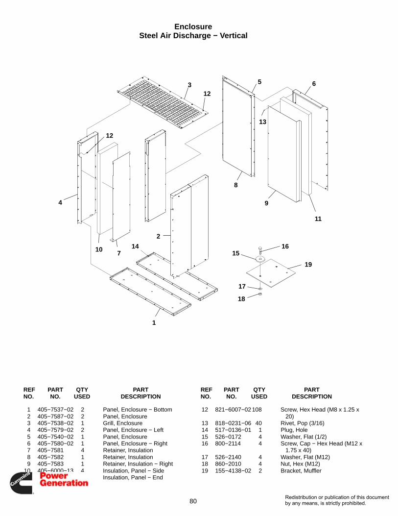
80
EnclosureSteel Air Discharge − Vertical
1
2
3
4
5 6
7
8
9
10
11
12
13
14
12
1516
17
18
19
REF PART QTY PART REF PART QTY PARTNO. NO. USED DESCRIPTION NO. NO. USED DESCRIPTION
1 405−7537−02 2 Panel, Enclosure − Bottom2 405−7587−02 2 Panel, Enclosure3 405−7538−02 1 Grill, Enclosure4 405−7579−02 2 Panel, Enclosure − Left5 405−7540−02 1 Panel, Enclosure6 405−7580−02 1 Panel, Enclosure − Right7 405−7581 4 Retainer, Insulation8 405−7582 1 Retainer, Insulation9 405−7583 1 Retainer, Insulation − Right
10 405−6000−13 4 Insulation, Panel − Side11 405−6000−14 2 Insulation, Panel − End
12 821−6007−02 108 Screw, Hex Head (M8 x 1.25 x20)
13 818−0231−06 40 Rivet, Pop (3/16)14 517−0136−01 1 Plug, Hole15 526−0172 4 Washer, Flat (1/2)16 800−2114 4 Screw, Cap − Hex Head (M12 x
1.75 x 40)17 526−2140 4 Washer, Flat (M12)18 860−2010 4 Nut, Hex (M12)19 155−4138−02 2 Bracket, Muffler
Redistribution or publication of this documentby any means, is strictly prohibited.

81
EnclosureAluminum Air Discharge − Vertical
1
2
3
4
5 6
7
8
9
10
11
12
13
1415
16
17
18
19
12
REF PART QTY PART REF PART QTY PARTNO. NO. USED DESCRIPTION NO. NO. USED DESCRIPTION
1 405−7761 2 Panel, Enclosure − Bottom2 405−7762 2 Panel, Enclosure3 405−7763 1 Grill, Enclosure4 405−7764 2 Panel, Enclosure − Left5 405−7765 1 Panel, Enclosure6 405−7766 1 Panel, Enclosure − Right7 405−7581 4 Retainer, Insulation8 405−7582 1 Retainer, Insulation9 405−7583 1 Retainer, Insulation − Right
10 405−6000−13 4 Insulation, Panel − Side11 405−6000−14 2 Insulation, Panel − End
12 821−6007−02 108 Screw, Hex Head (M8 x 1.25 x20)
13 818−0231−06 40 Rivet, Pop (3/16)14 517−0136−01 1 Plug, Hole (.812”)15 526−0172 4 Washer, Flat (1/2)16 800−2114 4 Screw, Cap − Hex Head (M12 x
1.75 x 40)17 526−2140 4 Washer, Flat (M12)18 860−2010 4 Nut, Hex (M12)19 155−4138−02 2 Bracket, Muffler
Redistribution or publication of this documentby any means, is strictly prohibited.

82
EnclosureSteel Air Discharge − Horizontal
12
3
4
5
6
7
8
9
10
11
12
1313
14
14
13
1516
17
18
23
1920
21
22
REF PART QTY PART REF PART QTY PARTNO. NO. USED DESCRIPTION NO. NO. USED DESCRIPTION
1 405−7537−02 1 Panel, Enclosure − Bottom2 405−7587−02 1 Panel, Enclosure3 405−7588−02 1 Grill, Enclosure4 405−7579−02 1 Panel, Enclosure − Left5 405−7581 2 Retainer, Insulation6 405−6000−13 2 Insulation, Panel − Side7 405−7589−02 1 Frame, Louver8 405−7590−02 1 Frame, Louver − Left9 405−7591−02 7 Louver − Outlet
10 405−7592 7 Retainer, Insulation − Louver11 405−7595−02 1 Panel, Air Baffle − Louver12 405−6000−12 7 Insulation, Panel − Louver13 821−6007−02 74 Screw, Hex Head (M8 x 1.25 x
20)
14 818−0231−06 134 Rivet, Pop (3/16)15 526−0172 4 Washer, Flat (1/2)16 800−2114 4 Screw, Cap − Hex Head (M12 x
1.75 x 40)17 526−2140 4 Washer, Flat (M12)18 860−2010 4 Nut, Hex (M12)19 405−7732−02 2 Bracket, Duct20 526−2109 8 Washer, Flat (M8)21 800−2058 4 Screw, Cap − Hex Head (M8 x
1.25 x 25)22 860−2008 4 Nut, Hex (M8)23 155−4138−02 2 Bracket, Muffler
Redistribution or publication of this documentby any means, is strictly prohibited.

83
EnclosureAluminum Air Discharge − Horizontal
12
3
4
5
6
7
8
9
10
11
12
1313
14
14
13
1516
17
18
24
1920
21
22
23
REF PART QTY PART REF PART QTY PARTNO. NO. USED DESCRIPTION NO. NO. USED DESCRIPTION
1 405−7761 1 Panel, Enclosure − Bottom2 405−7762 1 Panel, Enclosure3 405−7782 1 Grill, Enclosure4 405−7764 1 Panel, Enclosure − Left5 405−7581 2 Retainer, Insulation6 405−6000−13 2 Insulation, Panel − Side7 405−7783 1 Frame, Louver − Right8 405−7784 1 Frame, Louver − Left9 405−7785 7 Louver − Outlet
10 405−7592 7 Retainer, Insulation − Louver11 405−7786 1 Panel, Air Baffle − Louver12 405−6000−12 7 Insulation, Panel − Louver13 821−6007−02 74 Screw, Hex Head (M8 x 1.25 x
20)
14 818−0231−06 134 Rivet, Pop (3/16)15 526−0172 4 Washer, Flat (1/2)16 800−2114 4 Screw, Cap − Hex Head (M12 x
1.75 x 40)17 526−2140 4 Washer, Flat (M12)18 860−2010 4 Nut, Hex (M12)19 405−7787 2 Bracket, Duct20 526−2109 8 Washer, Flat (M8)21 800−2058 4 Screw, Cap − Hex Head (M8 x
1.25 x 25)22 860−2008 4 Nut, Hex (M8)23 818−0231−03 4 Rivet, Pop (3/16)24 155−4138−02 2 Bracket, Muffler
Redistribution or publication of this documentby any means, is strictly prohibited.

84
Emergency Stop Switch
1
2
3
4
5
6
7
8
10
9
REF PART QTY PART REF PART QTY PARTNO. NO. USED DESCRIPTION NO. NO. USED DESCRIPTION
1 Cover, Enclosure − AdapterPlug
405−7658−02 1 Steel405−7997 1 Aluminum
2 818−0231−02 4 Rivet, Pop3 319−5125 1 Cup, Switch4 330−0005 1 Box, Handy5 331−0027 1 Connector, Romex
6 338−4293 1 Harness, Switch − E-Stop7 815−0918 2 Screw, Machine − Flat Head −
Cross Recessed (#6−32 x.62)
8 308−0999 1 Switch, Push Button − E-Stop9 308−1177 1 Bezel, Switch
10 818−0231−06 4 Rivet, Pop
Redistribution or publication of this documentby any means, is strictly prohibited.

85
External Receptacle
1
2
3
4
5
6
7
8
9
REF PART QTY PART REF PART QTY PARTNO. NO. USED DESCRIPTION NO. NO. USED DESCRIPTION
1 323−2102−01 1 Receptacle2 330−0157 1 Cover, Receptacle3 330−0158 1 Cover, Outlet Box − Blank4 870−0183 4 Nut, Hex − W/ET (#6−32)5 331−0602 6 Clamp, Conduit
6 821−6002−03 6 Screw, Hex Head (M6 x 1 x 16)7 870−2054 3 Nut, Locking − Flange (M6 x 1)8 098−8185 1 Label, Information9 812−0068 4 Screw, Hex (#6−32 x 1.0)
Redistribution or publication of this documentby any means, is strictly prohibited.

86
Neutral Bar
1
2
2
3
4
4
4
4
5
5
5
5
6
7
8
9
9
1011
REF PART QTY PART REF PART QTY PARTNO. NO. USED DESCRIPTION NO. NO. USED DESCRIPTION
1 337−3514 2 Bar, Neutral2 332−3788 3 Lug, Solderless3 332−2744−07 2 Standoff, Insulator4 526−0399−20 14 Washer, Flat5 850−0050 10 Washer, Lock − Split (3/8)6 800−0048 2 Screw, Cap − Hex Head
(3/8−16 x .75)
7 800−0051 2 Screw, Cap − Hex Head(3/8−16 x 1.25)
8 800−0053 6 Screw, Cap − Hex Head(3/8−16 x 1.75)
9 862−0003 6 Nut, Hex − Heavy (3/8−16)10 098−5854−06 1 Label, Bus Marking11 098−5854−10 1 Label, Bus Marking
Redistribution or publication of this documentby any means, is strictly prohibited.

87
24VAC Transformer
1
2
3
3
4
4
5
REF PART QTY PART REF PART QTY PARTNO. NO. USED DESCRIPTION NO. NO. USED DESCRIPTION
1 315−1613 2 Transformer, Control2 815−0959−03 9 Screw, Cross Recessed − Pan
Head − W/ET (M3 x 0.5 x 8)
3 850−2003 9 Washer, Lock − Split (M3)4 860−2053 9 Nut, Hex (M3 x 0.5)5 854−0006 1 Washer, Lock − W/EIT (#6)
Redistribution or publication of this documentby any means, is strictly prohibited.

88
Current Transformer
1
2
REF PART QTY PART REF PART QTY PARTNO. NO. USED DESCRIPTION NO. NO. USED DESCRIPTION
1 Transformer, Current302−2057−15 3 (Ratio 552/1, 1104/1)302−2057−16 3 (Ratio 604/1, 1208/1)302−2057−18 3 (Ratio 656/1, 1312/1)302−2057−21 3 (Ratio 789/1, 1578/1)302−2057−23 3 (Ratio 867/1, 1734/1)302−2057−24 3 (Ratio 946/1, 1892/1)
2 856−0008 2 Washer, Lock − EIT (5/16”)
Redistribution or publication of this documentby any means, is strictly prohibited.
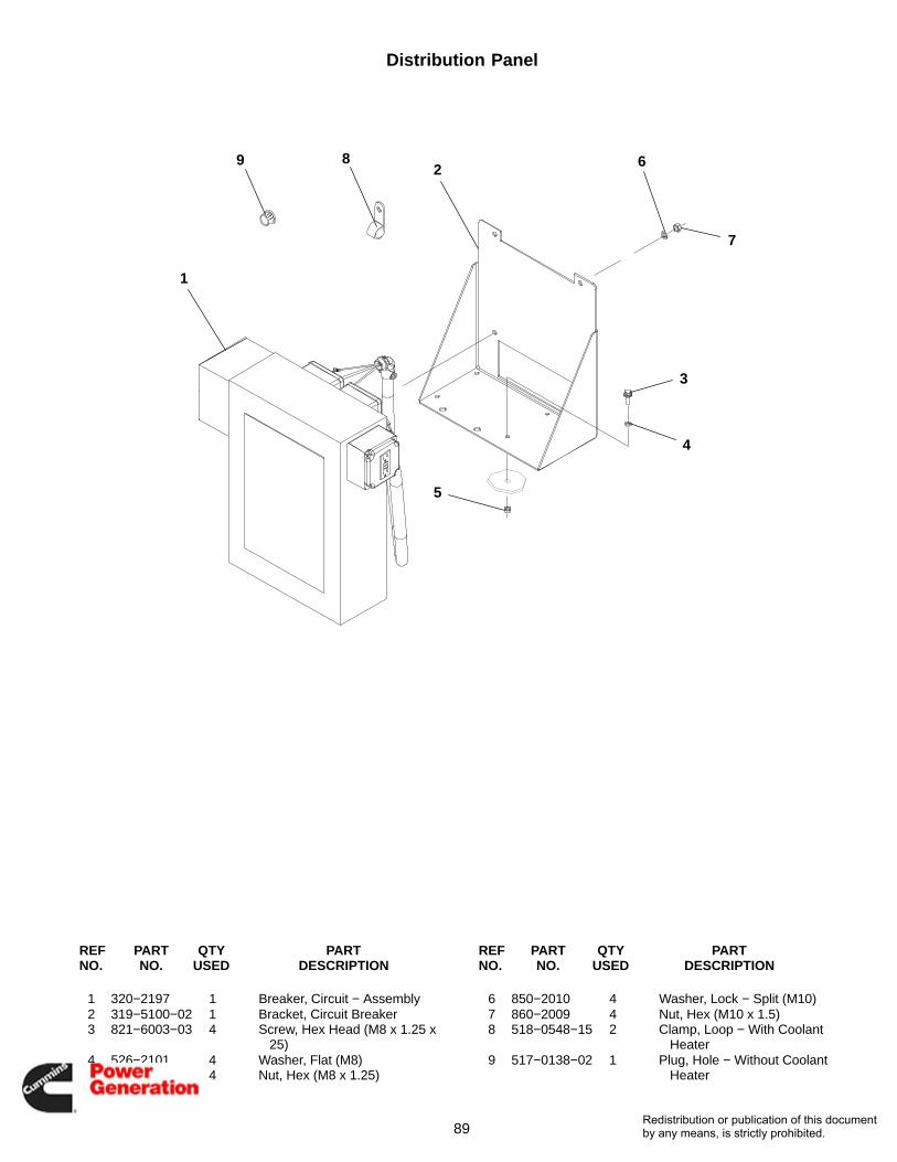
89
Distribution Panel
1
2
3
4
5
6
7
89
REF PART QTY PART REF PART QTY PARTNO. NO. USED DESCRIPTION NO. NO. USED DESCRIPTION
1 320−2197 1 Breaker, Circuit − Assembly2 319−5100−02 1 Bracket, Circuit Breaker3 821−6003−03 4 Screw, Hex Head (M8 x 1.25 x
25)4 526−2101 4 Washer, Flat (M8)5 860−2008 4 Nut, Hex (M8 x 1.25)
6 850−2010 4 Washer, Lock − Split (M10)7 860−2009 4 Nut, Hex (M10 x 1.5)8 518−0548−15 2 Clamp, Loop − With Coolant
Heater9 517−0138−02 1 Plug, Hole − Without Coolant
Heater
Redistribution or publication of this documentby any means, is strictly prohibited.
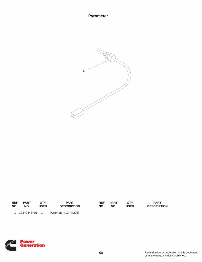
90
Pyrometer
1
REF PART QTY PART REF PART QTY PARTNO. NO. USED DESCRIPTION NO. NO. USED DESCRIPTION
1 193−0446−01 1 Pyrometer (12”) (M26)
Redistribution or publication of this documentby any means, is strictly prohibited.
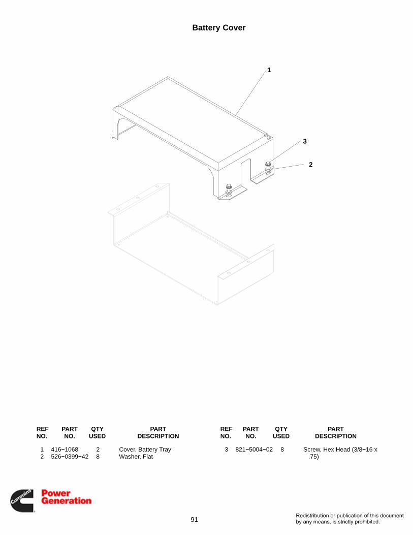
91
Battery Cover
1
2
3
REF PART QTY PART REF PART QTY PARTNO. NO. USED DESCRIPTION NO. NO. USED DESCRIPTION
1 416−1068 2 Cover, Battery Tray2 526−0399−42 8 Washer, Flat
3 821−5004−02 8 Screw, Hex Head (3/8−16 x.75)
Redistribution or publication of this documentby any means, is strictly prohibited.
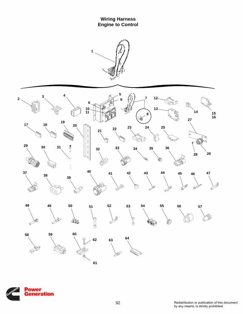
92
Wiring HarnessEngine to Control
23 7
8
412
1314 15
16
17 20
21 22 23 24
31 3332 34 35 36
3839
40 41 42 43 44 45 4746
49
27
50 51 52
28 26
1819
25
29 30
48 53
37
54 55 56 57
58
1
5
69
1011
59 60
63
61
62 64
Redistribution or publication of this documentby any means, is strictly prohibited.

93
Harness WiringEngine to Control
REF PART QTY PART REF PART QTY PARTNO. NO. USED DESCRIPTION NO. NO. USED DESCRIPTION
1 338−4072 1 Harness, Wiring − Engine toControl (Includes theFollowing Parts)
2 Plug, Connector (23 Pin)323−1605−02 1 Natural (P4)323−1605−03 1 Gray (P5)
3 323−1624 1 Wedge, Plug (6 Pin) (P7)4 323−1623 1 Plug (6 Pin) (P7)5 307−2970−02 1 Bracket, Relay6 307−2968−04 5 Relay, Power7 338−4024 1 Harness, Wiring − Includes
Potentiometer8 151−0402 1 Potentiometer9 308−1107 1 Switch, Toggle − Locking Lever
10 850−0114−51 10 Washer, Lock − Split (M4)11 823−1001−04 10 Screw, Machine − Pan Head
(M4 x 0.7 x 12)12 332−2878 4 End, Bracket − Terminal13 332−3444 A/R Block, Terminal14 332−3446 A/R Cover, Terminal15 332−3448−01 4 Bracket, Terminal Block (With
Pin)16 332−3448−02 4 Bracket, Terminal Block
(Without Pin)17 332−3447−05 2 Plug, Terminal Block18 332−3447−13 2 Plug, Terminal Block19 332−3762−03 2 Jumper, Terminal − 10 Place20 332−2879−05 1 Rail, Terminal21 332−3447−02 3 Plug, Terminal Block − 4 Place22 332−3447−05 1 Plug, Terminal Block − 10 Place23 332−2878 3 End, Bracket − Terminal24 321−0344 2 Block, Fuse25 321−0373 10 Block, Fuse26 323−1920 1 Connector − 9 Pin27 319−4439−02 1 Bracket, Connector28 815−0902 4 Screw, Cross Recessed − Pan
Head − W/ET (#6−32 x .375)
29 323−1918 1 Connector − 31 Pin30 323−1919 1 Connector − 50 Pin31 338−2592−02 1 Cable, Magnetic Pickup (P12)32 323−1666 1 Connector, Socket (E1)33 323−1494 1 Connector, Receptacle − 3 Pin34 323−1502 1 Wedge, Receptacle − 3 Pin35 323−1445 8 Seal, Cable36 323−1540 2 Connector, Socket (E2, E4)37 323−1652 1 Connector, 2-Way38 323−1637 2 Connector, Socket (E−6)39 338−3285 1 Harness, Jumper (E−6)40 323−1493 2 Plug − 3 Pin (P3)41 323−1503 1 Wedge − 3 Pin (P3)42 332−2571 1 Terminal, Receptacle (S4)43 323−1614−01 30 Socket, Contact (P4, P5)44 323−1667 3 Socket, Contact (E1)45 332−3096−01 4 Socket, Contact (E2, E4)46 323−1718 2 Pin, Contact47 323−1752 27 Socket, Contact48 323−1492 15 Socket, Contact49 323−1491 10 Pin, Contact50 332−3491−01 54 Pin, Contact (TB1, TB2, TB3)51 321−0372−05 10 Fuse − 10 Amp52 323−1444 2 Socket, Contact (E6)53 321−0363−31 2 Fuse − 20 Amp54 323−1924 1 Connector, Housing (50 Pin)55 508−1090 1 Grommet56 323−1765 1 Connector, Housing (S7)57 323−1708 3 Seal (S7)58 323−1709 3 Socket, Contact (S7)59 323−1939 16 Lock, Connector60 323−1948 1 Bracket, Connector61 870−0131 1 Nut, Hex − W/ET (#10−32)62 815−0026 1 Screw, Truss (#10−32 x 3/8)63 323−1712 1 Plug, Cavity64 332−3447−13 2 Plug, Terminal Block
Redistribution or publication of this documentby any means, is strictly prohibited.
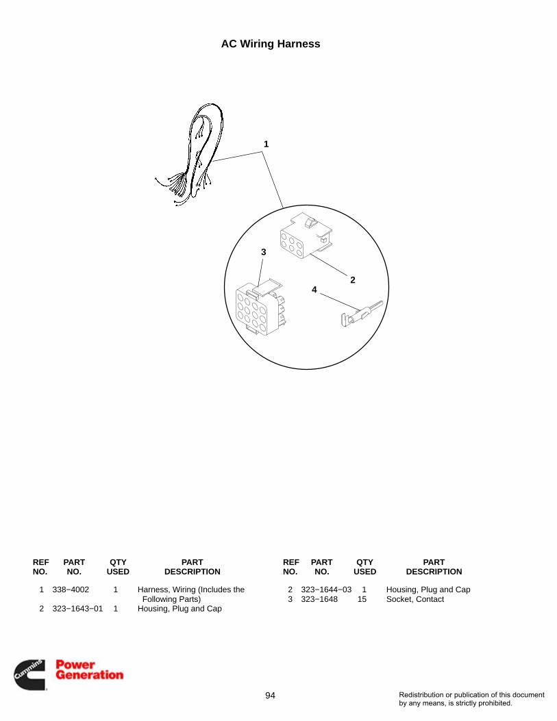
94
AC Wiring Harness
1
2
3
4
REF PART QTY PART REF PART QTY PARTNO. NO. USED DESCRIPTION NO. NO. USED DESCRIPTION
1 338−4002 1 Harness, Wiring (Includes the Following Parts)
2 323−1643−01 1 Housing, Plug and Cap
2 323−1644−03 1 Housing, Plug and Cap3 323−1648 15 Socket, Contact
Redistribution or publication of this documentby any means, is strictly prohibited.

95
Circuit Breaker and Disconnect SwitchUL Listed, IEC Conformity
12
3
4
5
6
REF PART QTY PART REF PART QTY PARTNO. NO. USED DESCRIPTION NO. NO. USED DESCRIPTION
1 The following listed CircuitBreakers and DisconnectSwitches include lugs andmounting hardware.
Breaker, Circuit3 Pole (UL, IEC)
320−1959−06 1 125 Amp320−1959−05 1 150 Amp320−1959−04 1 175 Amp320−1959−03 1 200 Amp320−1959−02 1 225 Amp320−1959−01 1 250 Amp320−1960−06 1 300 Amp320−1960−05 1 350 Amp320−1960−04 1 400 Amp320−1960−03 1 450 Amp320−1960−02 1 500 Amp320−1960−01 1 600 Amp320−1964−05 1 700 Amp320−1964−04 1 800 Amp320−1964−03 1 900 Amp320−1964−02 1 1000 Amp320−1964−01 1 1200 Amp
4 Pole (IEC)320−1960−10 1 320 Amp320−1960−09 1 400 Amp320−1960−08 1 500 Amp320−1960−07 1 630 Amp320−1964−08 1 800 Amp320−1964−07 1 1000 Amp320−1964−06 1 1250 Amp
Disconnect Switches3 Pole (UL, IEC)
320−1990−02 1 400 Amp320−1990−01 1 600 Amp320−1992−02 1 800 Amp320−1992−01 1 1200 Amp
2 Package, Hardware −Mounting (Includes Screws,Nuts and Lock Washers − 1Package Required PerSwitch)
320−1986−08 1 Used With 320−1959−XXCircuit Breakers
320−1986−01 1 Used With 320−1964−XXCircuit Breakers and 320−1992−XX Disconnect Switches
320−1986−07 1 Used With 320−1990−XXDisconnect Switches
Accessories, Circuit Breaker:The following are used on 320−1959−XX CircuitBreakers
3 320−1981−01 1 Switch − Used as a Trip Alarm or Auxiliary Contact
4 320−1981−03 1 24 Volt Shunt TripAccessories, Circuit Breaker:
The following are used on 320−1964−XX CircuitBreakers
5 320−1977−01 1 Switches − Includes 1 Trip Alarm and 1 Auxiliary Contact
6 320−1977−03 1 24 Volt Shunt Trip
Redistribution or publication of this documentby any means, is strictly prohibited.

96
Circuit Breaker BoxWithout Enclosure
1
2
3
4
5
6
7
8
9
10 11
12
1212
12
13
14
15
1617
18
19
20
21
22
23
2425
26
27
28
28 29
2930
Redistribution or publication of this documentby any means, is strictly prohibited.

97
Circuit Breaker BoxWithout Enclosure
REF PART QTY PART REF PART QTY PARTNO. NO. USED DESCRIPTION NO. NO. USED DESCRIPTION
1 870−0504 16 Nut, Self−Retaining (M6)2 319−3169 1 Box, Circuit Breaker3 337−3515−01 1 Bar Assembly, Neutral (See
Separate Page for Components)
4 332−2001 1 Lug, Solderless5 319−1915 1 Panel − Top6 Cover
319−1917 1 All Except 4 Pole Switches Mounted on the Right Side When Facing Control
319−2463 1 4 Pole Switches Mounted on the Right Side When Facing Control
7 319−3284 1 Brace, Cover8 319−3333 1 Brace, Cover9 091−0002 1 Strip, Copper (Quantity Used As
Required)10 319−3183 1 Panel − Bottom11 Cup
319−2431−27 1 1-7/8” x 3-1/32” Opening319−2431−30 1 3-5/16” x 4-3/8” Opening319−2431−31 1 2-1/2” x 4-9/16” Opening
12 821−6002−03 53 Screw, Self−Locking − HexWasher Head (M6 x 1.0 x16mm)
13 856−0010 1 Washer, Lock − EIT (3/8”)14 526−2120 1 Washer, Flat (M10)15 821−2034 2 Screw, Self−Locking − Hex
Washer Head (M6 x 1.0 x 20mm)
16 850−2010 1 Washer, Lock − Spring (M10)17 800−2088 1 Screw, Cap − Hex Head
(M10 x 1.5 x 35mm)
18 870−2054 4 Nut, Hex − Flange (M6)19 Lead (Quantity Used As
Required) 39” (WithoutMarkings) (#1/0 Wire)
226−4406−03 1 1/2” Ring Terminal End to 1”Stripped End
226−4406−04 1 1/2” Ring Terminal End to1/2” Ring Terminal End
20 508−1092 − Edging − Bulk (Order By TheFoot − 3 Feet Required)
21 Label, Marker (10 CharactersPer Card) (Quantity Used AsRequired)
098−5854−06 1 Marked ”L”098−5854−07 1 Marked ”1”098−5854−08 1 Marked ”2”098−5854−09 1 Marked ”3”098−5854−10 1 Marked ”0”
22 319−3329 1 Bracket, MountingThe following 4 hardware items
are used to fasten the load leads to the generator and neutral bar. Quantity used as required.
23 800−2116 1 Screw, Cap − Hex Head(M12 x 50mm)
24 860−2010 1 Nut, Hex (M12)25 850−2012 1 Washer, Lock − Spring (M12)26 526−2140 1 Washer, Flat (M12)27 332−2744−07 1 Standoff, Insulator28 800−0048 2 Screw, Cap − Hex Head
(3/8−16 x .75)29 850−0050 2 Washer, Lock (3/8)30 526−0029 1 Washer, Flat (3/8)
Redistribution or publication of this documentby any means, is strictly prohibited.
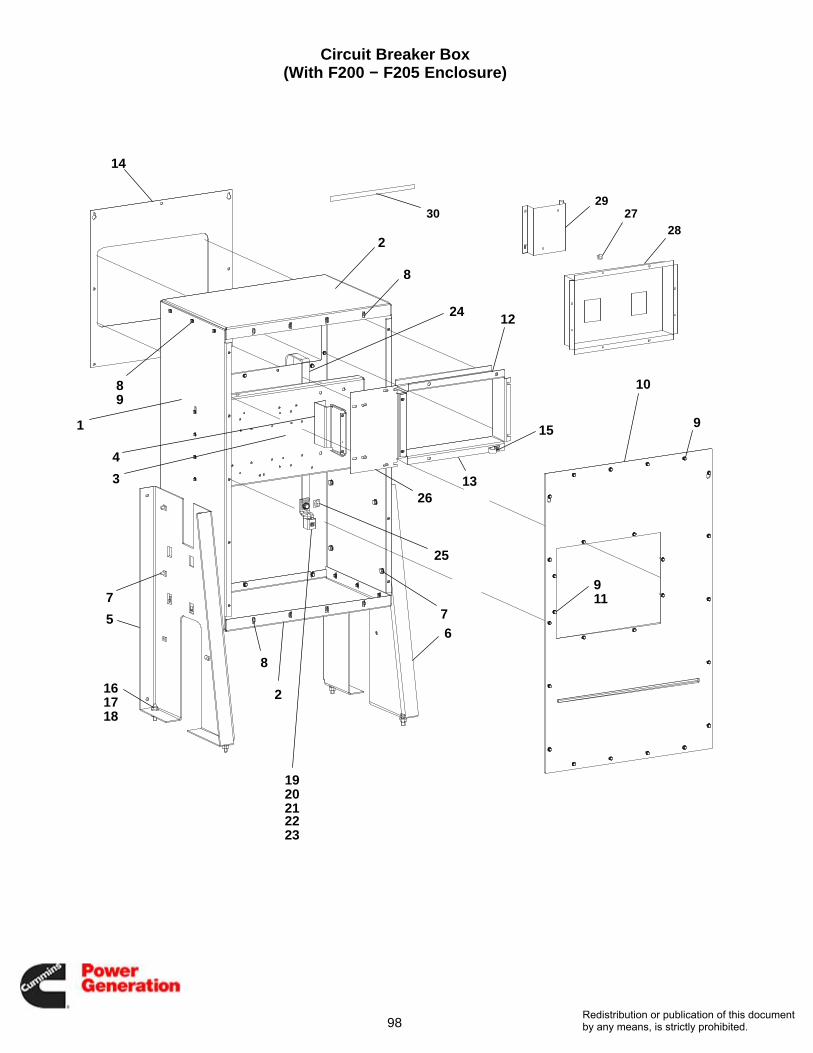
98
Circuit Breaker Box(With F200 − F205 Enclosure)
1
2
2
3
4
56
77
8
8
8
9
9
9
10
11
12
13
14
15
161718
1920212223
24
25
26
2728
2930
Redistribution or publication of this documentby any means, is strictly prohibited.

99
Circuit Breaker Box(With F200 − F205 Enclosure)
REF PART QTY PART REF PART QTY PARTNO. NO. USED DESCRIPTION NO. NO. USED DESCRIPTION
1 319−5106−02 1 Box, Circuit Breaker2 319−4983−02 2 Cover, Box3 319−4955−02 1 Bracket, Circuit Breaker −
Mounting4 319−4979−02 1 Bracket, Circuit Breaker5 319−5092−02 1 Bracket, Circuit Breaker6 319−5093−02 1 Bracket, Circuit Breaker7 821−6004−01 8 Screw, Hex Head (M10 x 1.5 x
20)8 870−0504 14 Nut, Captive − Floating9 821−6002−03 66 Screw, Hex Head (M6 x 1 x 16)
10 319−5112−02 1 Cover, Circuit Breaker11 870−2054 6 Nut, Locking − Flange (M6 x 1)12 Cover, Circuit Breaker
319−5113−02 1 4CDE Generator319−5115−02 1 4F Generator
13 Cover, Circuit Breaker319−5114−02 1 4CDE Generator319−5116−02 1 4F Generator
14 Cover, Circuit Breaker319−5108−02 1 4CDE Generator319−5109−02 1 4F Generator
15 518−0548−58 1 Clamp, Hose16 800−2114 4 Screw, Cap − Hex Head (M12 x
1.75 x 40)17 860−2010 4 Nut, Hex (M12 x 1.75)18 526−2140 8 Washer, Flat (M12)19 332−2001 1 Lug, Solderless20 856−0010 1 Washer, Lock − W/EIT (3/8)
21 526−0399−62 1 Washer, Flat (M10)22 850−0114−55 1 Washer, Lock − Split (M10)23 800−3017−39 1 Screw, Cap − Hex Head (M10 x
1.5 x 35)24 337−3538−03 1 Strap, Ground25 098−6537 1 Label, Ground26 319−5140−02 1 Cover, Circuit Breaker27 870−2054 4 Nut, Hex − Flange (M6)28 Cup, Circuit Breaker
319−4962−02 1 CK − 84mm x 112mm Opening
319−4964−02 1 NSF − 31mm x 77mmOpening
319−4965−02 1 NSJ − 64mm x 116mmOpening
319−4967−02 1 CK and NSJ − 84mm x 112mm Opening
319−4968−02 1 CK and NSF − 84mm x 112mm Opening
319−4969−02 1 NSJ and NSF − 64mm x 116mm Opening
29 091−0002 1 Strip, Copper (Used forwrapping end of leads beforesecuring to circuit breakersand disconnect switches)(Quantity Used As Required)
30 319−4980−02 1 Bracket, Circuit Breaker − Riser− NSF
Redistribution or publication of this documentby any means, is strictly prohibited.

100
Control Label
REF PART QTY PART REF PART QTY PARTNO. NO. USED DESCRIPTION NO. NO. USED DESCRIPTION
1 098−8058 1 Label, Control
Redistribution or publication of this documentby any means, is strictly prohibited.

101
Miscellaneous
12
3
45
REF PART QTY PART REF PART QTY PARTNO. NO. USED DESCRIPTION NO. NO. USED DESCRIPTION
1 501−0751 1 Line, Flexible − Fuel(1/2 Fuel In)
2 501−0752−02 1 Line, Flexible − Fuel(3/8 Fuel Out)
3 517−0286−04 1 Plug, Cap4 800−0048 4 Screw, Cap − Hex Head (3/8−16
x .75)5 416−0850 4 Bracket, Battery
Redistribution or publication of this documentby any means, is strictly prohibited.

102
Accessories
These parts must be purchased through the Accessories Business Unit, see your Cummins/Onan Distributer. Forother accessories such as batteries, fuel tanks and annunciators contact the Accessories Business Unit.
REF PART QTY PART REF PART QTY PARTNO. NO. USED DESCRIPTION NO. NO. USED DESCRIPTION
1 Muffler − Industrial155−2340−05 1 5” Flange155−2340−01 1 6” Flange
2 Muffler − Residential155−2341−05 1 6” Flange155−2341−01 1 6” Flange
3 155−2342−01 1 Muffler − Critical6” Flange
4 Package, Pipe − Exhaust155−2549 1 5” Silencer155−2550 1 6” Silencer155−2551 1 8” Silencer
5 307−1056 1 Relay, Auxiliary − 3PDT(24V)
Redistribution or publication of this documentby any means, is strictly prohibited.
Numerical Index
Part No. Page Part No. Page Part No. Page Part No. Page
103
091−0002, 97, 99
098−5854−06, 86, 97
098−5854−07, 97
098−5854−08, 97
098−5854−09, 97
098−5854−10, 86, 97
098−6537, 99
098−7451, 37
098−8058, 100
098−8120, 21
098−8185, 85
102−1335, 9
128−0117, 37
128−0154, 39
128−0154−01, 39
128−0154−06, 39
130−3660−01, 23
130−3931, 37
130−3932−01, 37
130−3932−02, 37
130−4074, 37
130−4075, 37
130−4378, 37
130−4534, 37
130−4552, 33
130−4848, 39
130−5444, 37
130−5445−02, 37
130−5446−01, 37
130−5447−01, 37
130−5449−02, 37
130−5450−02, 37
130−5451−02, 37
130−5452−02, 37
130−5454−02, 37
130−5455−02, 37
130−5456−02, 37
130−5457−02, 37
130−5459−02, 37
130−5475−02, 37
130−5480, 37
130−5481, 37
130−5482, 37
130−5527−02, 39
130−5528−02, 31
130−5532−02, 31
130−5555−02, 26
130−5884−03, 47, 49
130−5884−04, 47, 49
140−0757, 11
140−1260, 11
140−1347, 11
140−1415, 11
140−1548, 11
140−2102, 10
140−2636, 11
140−2637, 11
140−2638, 11
140−2655, 10, 11
140−2656, 10, 11
140−3288−02, 10
140−3343−02, 10, 11
140−3362−02, 10
140−3388−02, 11
149−2699−01, 20
149−2699−02, 20
149−2699−03, 20
149−2699−04, 20
149−2699−05, 20
149−2699−06, 20
149−2699−11, 20
149−2699−12, 20
149−2699−13, 20
149−2699−14, 20
149−2699−15, 20
149−2699−16, 20
149−2710−01, 20
149−2710−02, 20
151−0402, 93
151−0411, 9
155−0658−01, 25
155−1241−01, 25
155−2062−06, 26, 27
155−2159, 26
155−2340−01, 102
155−2340−05, 102
155−2341−01, 102
155−2341−05, 102
155−2342−01, 102
155−2409−04, 25
155−2441, 26
155−2500, 28
155−2549, 102
155−2550, 102
155−2551, 102
155−3021, 31
155−3139, 26
155−3480, 37
155−3509−02, 26
155−3510, 26
155−3540, 26
155−3543, 27, 28
155−3554, 28
155−4022, 27
155−4026, 28
155−4045, 28
155−4047, 28
155−4048−02, 28
155−4053, 27, 28
155−4059−02, 27
155−4062, 28
155−4064, 27, 28
155−4134−02, 41
155−4138−02, 80, 81, 82, 83
155−4162, 27
159−1208−01, 13, 14, 15
159−1299, 13, 14, 15
159−1390, 23
159−1573−01, 19
159−1573−02, 19
159−1573−03, 19
159−1573−04, 19
159−1573−05, 19
159−1573−06, 19
159−1573−11, 19
159−1573−12, 19
159−1573−13, 19
159−1573−14, 19
159−1573−15, 19
159−1573−16, 19
159−1573−21, 19
159−1573−22, 19
159−1573−23, 19
159−1573−24, 19
159−1573−25, 19
159−1573−26, 19
159−1577−01, 19
191−2341, 50
193−0432, 9
193−0444, 9
193−0446−01, 90
193−0468, 35
201−3459−01, 66
201−3459−02, 66
201−3459−03, 66
201−3459−04, 66
201−3460, 65
211−0431, 65
220−4248, 65
220−4468−01, 66
220−4468−02, 66
220−4468−03, 66
220−4468−04, 66
220−4468−07, 66
220−4468−08, 66
220−4468−09, 66
220−4468−10, 66
226−4406−03, 97
226−4406−04, 97
231−0322, 65
232−3482, 65
232−3518−01, 65
232−3520−01, 65
232−3522, 65
232−3523, 65
232−3524, 65
232−3850, 63
232−3966, 65
232−3981−01, 65
234−0889, 65
249−0797, 65
249−5080−02, 66
Redistribution or publication of this documentby any means, is strictly prohibited.

Numerical Index
Part No. Page Part No. Page Part No. Page Part No. Page
104
249−5080−03, 66
249−5080−04, 66
249−5080−05, 66
249−5081−02, 66
249−5081−03, 66
249−5081−04, 66
249−5081−05, 66
300−3464, 16
300−4079, 61
300−4080−01, 61
300−4080−02, 61
300−4083, 61
300−4286, 59
300−4306, 61
300−4308−01, 61
300−4308−03, 61
300−4309−01, 61
300−4309−02, 61
300−4309−03, 61
300−4462, 61
300−4462−01, 61
300−4481, 59
300−4515−01, 56, 61
300−4515−02, 56, 61
300−4608−01, 59
300−4608−02, 59
300−4610−01, 59
300−4610−02, 59
300−5815, 20
301−6987, 69
301−9511, 54
301−9512, 53
301−9629, 53
302−2009−01, 59
302−2009−02, 59
302−2009−03, 59
302−2009−04, 59
302−2010, 59
302−2011, 59
302−2012, 59
302−2057−15, 88
302−2057−16, 88
302−2057−18, 88
302−2057−21, 88
302−2057−23, 88
302−2057−24, 88
307−1056, 102
307−1056−01, 68
307−2621−02, 9
307−2677−02, 16
307−2817−02, 21
307−2859, 33
307−2968−04, 93
307−2970−02, 93
307−3003−01, 69
308−0852, 16
308−0912, 16
308−0913−06, 13, 14
308−0916−01, 24
308−0963−01, 22
308−0973, 21
308−0998, 59
308−0999, 59, 84
308−1045, 59
308−1046, 59
308−1107, 93
308−1177, 84
309−0269, 9
309−0649, 31
309−0701−01, 19
309−0701−02, 19
309−0701−03, 19
309−0701−04, 19
309−0701−05, 19
309−0701−07, 19
309−0701−08, 19
309−0702−01, 19
309−0702−02, 19
309−0702−03, 19
309−0702−04, 19
309−0702−05, 19
309−0702−07, 19
309−0702−08, 19
309−0703−01, 20
309−0708−01, 19
309−0708−02, 19
315−1613, 87
319−0485, 16
319−0486, 16
319−0489, 24
319−0490, 24
319−1345, 53
319−1687, 61
319−1915, 51, 97
319−1916, 51
319−1917, 97
319−2220, 54
319−2236, 9
319−2247, 67
319−2431−27, 97
319−2431−30, 97
319−2431−31, 97
319−2463, 97
319−2768, 53
319−2814, 33
319−2815, 31
319−2918, 31
319−3169, 51, 97
319−3183, 51, 97
319−3251, 51
319−3255, 53
319−3257, 53
319−3270−01, 53
319−3278, 53
319−3284, 51, 97
319−3287−01, 53
319−3287−02, 53
319−3329, 97
319−3333, 97
319−4439−02, 93
319−4453−02, 53
319−4955−02, 99
319−4962−02, 99
319−4964−02, 99
319−4965−02, 99
319−4967−02, 99
319−4968−02, 99
319−4969−02, 99
319−4979−02, 99
319−4980−02, 99
319−4983−02, 99
319−5025−02, 55
319−5026−02, 55
319−5027−02, 55
319−5038−02, 69
319−5056−02, 21
319−5092−02, 99
319−5093−02, 99
319−5100−02, 89
319−5106−02, 99
319−5108−02, 99
319−5109−02, 99
319−5112−02, 99
319−5113−02, 99
319−5114−02, 99
319−5115−02, 99
319−5116−02, 99
319−5125, 84
319−5140−02, 99
320−1653, 16
320−1654, 16
320−1959−01, 95
320−1959−02, 95
320−1959−03, 95
320−1959−04, 95
320−1959−05, 95
320−1959−06, 95
320−1960−01, 95
320−1960−02, 95
320−1960−03, 95
320−1960−04, 95
320−1960−05, 95
320−1960−06, 95
320−1960−07, 95
320−1960−08, 95
320−1960−09, 95
320−1960−10, 95
320−1964−01, 95
320−1964−02, 95
320−1964−03, 95
320−1964−04, 95
320−1964−05, 95
Redistribution or publication of this documentby any means, is strictly prohibited.

Numerical Index
Part No. Page Part No. Page Part No. Page Part No. Page
105
320−1964−06, 95
320−1964−07, 95
320−1964−08, 95
320−1977−01, 95
320−1977−03, 95
320−1981−01, 95
320−1981−03, 95
320−1986−01, 95
320−1986−07, 95
320−1986−08, 95
320−1990−01, 95
320−1990−02, 95
320−1992−01, 95
320−1992−02, 95
320−2197, 89
321−0307−03, 61
321−0344, 93
321−0363−31, 93
321−0372−05, 93
321−0373, 93
322−0369−02, 16
322−0403−02, 16
323−1410−01, 68
323−1411−01, 68
323−1444, 93
323−1445, 33, 93
323−1491, 33, 93
323−1492, 33, 93
323−1493, 93
323−1494, 33, 93
323−1500, 33
323−1502, 33, 93
323−1503, 93
323−1504, 33
323−1540, 93
323−1605−01, 67
323−1605−02, 93
323−1605−03, 67, 93
323−1605−04, 67
323−1614−01, 67, 93
323−1623, 93
323−1624, 93
323−1637, 93
323−1643−01, 94
323−1644−03, 94
323−1648, 94
323−1652, 33, 93
323−1666, 93
323−1667, 93
323−1708, 93
323−1709, 93
323−1712, 93
323−1718, 33, 93
323−1752, 93
323−1765, 93
323−1918, 93
323−1919, 93
323−1920, 93
323−1924, 93
323−1939, 93
323−1948, 93
323−2102−01, 85
327−1301, 70
330−0005, 84
330−0141−03, 63
330−0141−04, 63
330−0142, 63
330−0157, 85
330−0158, 85
331−0027, 16, 20, 63, 84
331−0042, 16, 33
331−0554, 33
331−0555, 33
331−0570, 33
331−0602, 85
332−0941, 50
332−0942, 61
332−1445, 59
332−1468, 33
332−1469, 33
332−1789, 61
332−2001, 51, 97, 99
332−2420, 56, 61, 69
332−2571, 93
332−2605, 16
332−2634, 61
332−2744−07, 86, 97
332−2878, 67, 93
332−2879−05, 67, 93
332−3009, 65
332−3023, 63
332−3024−14, 63
332−3096−01, 93
332−3125−02, 67
332−3126−01, 67
332−3196, 31
332−3235, 61, 70
332−3262, 59
332−3440, 33
332−3444, 67, 93
332−3446, 67, 93
332−3447−02, 93
332−3447−05, 93
332−3447−10, 67
332−3447−13, 67, 93
332−3448−01, 67, 93
332−3448−02, 67, 93
332−3491−01, 67, 93
332−3762−02, 67
332−3762−03, 93
332−3788, 86
333−0407−02, 34
333−0407−04, 34
333−0407−05, 34
333−0407−06, 34
333−0438−03, 63
333−0634−01, 31
333−0634−02, 31
333−0682, 21
333−0683, 21
335−0173−03, 56
335−0173−04, 63
337−0049, 61
337−0090, 44
337−0090−02, 47, 49
337−2402, 13, 14, 15
337−3514, 86
337−3515−01, 97
337−3538−03, 99
338−2382, 16
338−2592−02, 93
338−2800, 13
338−2809, 13, 14
338−2934, 59
338−2937, 59
338−3232, 69
338−3285, 93
338−3348, 65
338−3385, 33
338−3923−07, 33
338−4002, 94
338−4019, 67
338−4023, 67
338−4024, 93
338−4072, 93
338−4293, 84
338−4295−01, 71, 72
338−4295−02, 78, 79
338−4295−03, 71, 72, 78, 79
338−4360−01, 21
338−4360−02, 21
338−4426, 20
357−0030, 33
357−0093, 65
357−0114, 56, 61
399−0117, 13
399−0121, 13
399−0122, 13
399−0123, 13
399−0124, 13
402−0070, 37
402−0354, 69
402−0508, 37
402−0510, 67
402−0527, 61
402−0610, 9, 13, 14, 15
402−0729, 53
402−0779−03, 44
402−0779−07, 44
402−0816−01, 47, 49
402−0820, 47, 49
403−3362, 47, 49
Redistribution or publication of this documentby any means, is strictly prohibited.

Numerical Index
Part No. Page Part No. Page Part No. Page Part No. Page
106
403−4530−02, 44
403−5034−02, 45
403−5111−02, 47, 49
405−3980, 39
405−4104, 39
405−4106, 39
405−4107, 39
405−4110, 39
405−4111, 39
405−4112, 39
405−4404, 39
405−4405, 39
405−6000−08, 41, 43
405−6000−09, 41, 43
405−6000−10, 41, 43
405−6000−11, 41, 43
405−6000−12, 82, 83
405−6000−13, 80, 81, 82, 83
405−6000−14, 80, 81
405−6000−15, 73, 74
405−6943−02, 39
405−6946−02, 39
405−6947−02, 39
405−6949−02, 39
405−6950−02, 39
405−7249−02, 53
405−7254−02, 53
405−7500−02, 41
405−7501−02, 41
405−7503−01, 78, 79
405−7503−02, 78, 79
405−7526−02, 47
405−7527−02, 47
405−7528−02, 47
405−7529−02, 47
405−7531−02, 78
405−7534−02, 73
405−7534−04, 73
405−7535, 73, 74
405−7537−02, 80, 82
405−7538−02, 80
405−7539−01, 71, 72
405−7539−02, 71, 72
405−7540−02, 80
405−7553−02, 73
405−7554−02, 73
405−7557−02, 73
405−7558−02, 73
405−7569, 71, 72
405−7574−02, 41
405−7574−04, 41
405−7577−02, 41, 43
405−7577−04, 41, 43
405−7579−02, 80, 82
405−7580−02, 80
405−7581, 80, 81, 82, 83
405−7582, 80, 81
405−7583, 80, 81
405−7587−02, 80, 82
405−7588−02, 82
405−7589−02, 82
405−7590−02, 82
405−7591−02, 82
405−7592, 82, 83
405−7595−02, 82
405−7596−02, 78
405−7599−02, 78
405−7600−02, 78
405−7604−02, 41
405−7606−02, 71
405−7616, 41, 43
405−7617, 41, 43
405−7618, 41, 43
405−7620, 41, 43
405−7626, 41, 43
405−7628, 41, 43
405−7630, 41, 43
405−7631−01, 71
405−7631−02, 71
405−7632−02, 75
405−7633, 71
405−7634−02, 75
405−7635−02, 75
405−7637, 41, 43
405−7657−04, 47, 49
405−7658−02, 84
405−7666−02, 55
405−7720−01, 72
405−7720−02, 72
405−7721−01, 74
405−7721−02, 74
405−7722, 74
405−7723, 74
405−7724, 74
405−7725, 74
405−7726, 72
405−7727, 76
405−7728, 72
405−7729, 76
405−7730, 76
405−7732−02, 82
405−7734−04, 41
405−7735−04, 41
405−7736−02, 41
405−7737−02, 41
405−7738−02, 41
405−7739−02, 41
405−7740−02, 41, 43
405−7741−02, 41
405−7742−02, 41, 43
405−7743−02, 41
405−7744−02, 41
405−7745, 41, 43
405−7746, 41, 43
405−7754, 71, 72, 78
405−7755−02, 73
405−7756−02, 41
405−7761, 81, 83
405−7762, 81, 83
405−7763, 81
405−7764, 81, 83
405−7765, 81
405−7766, 81
405−7782, 83
405−7783, 83
405−7784, 83
405−7785, 83
405−7786, 83
405−7787, 83
405−7800, 74
405−7810−02, 75
405−7812−01, 41, 43
405−7812−02, 41, 43
405−7825, 76
405−7835, 43
405−7836, 43
405−7837, 43
405−7838, 43
405−7839, 43
405−7840, 43
405−7842, 43
405−7843, 43
405−7844−02, 43
405−7845−02, 43
405−7846, 43
405−7847, 43
405−7848, 43
405−7849, 43
405−7850, 43
405−7851, 43
405−7853, 43
405−7854, 43
405−7855, 43
405−7863−02, 41
405−7872, 49
405−7873, 49
405−7874, 49
405−7875, 49
405−7879, 43
405−7882, 41, 43
405−7883, 41, 43
405−7884−02, 41
405−7885−02, 41
405−7922, 77
405−7923, 77
405−7924, 79
405−7925, 79
405−7997, 84
406−0761−03, 59
406−0929, 41, 43, 71, 72
406−0970−01, 41, 43
406−0970−02, 41, 43
Redistribution or publication of this documentby any means, is strictly prohibited.

Numerical Index
Part No. Page Part No. Page Part No. Page Part No. Page
107
406−0970−03, 41, 43
406−0970−04, 41, 43
406−0972−02, 39, 41, 43
406−1049−01, 41, 43
406−1049−02, 41, 43
415−0565−15, 13, 14
415−0566−15, 13, 14, 15
415−0650−01, 15
415−0651−19, 15
415−0652, 15
415−0654, 15
415−0655, 15
415−0656−21, 15
415−0657, 15
415−0660, 15
415−0727, 13, 14
415−0728, 15
416−0680, 50
416−0850, 101
416−1019, 50
416−1068, 91
416−1084, 50
416−1092, 50
416−1097, 50
420−0609−01, 19
420−0609−02, 19
420−0609−03, 19
420−0609−04, 19
420−0609−05, 19
420−0609−07, 19
420−0609−08, 19
420−0610−01, 20
420−0610−02, 20
420−0610−03, 20
420−0610−04, 20
420−0610−05, 20
420−0610−06, 20
425−1799, 61, 65
501−0216, 37
501−0551−01, 37
501−0751, 101
501−0752−02, 101
502−0827, 9, 31, 47, 49
502−0876, 47, 49
502−0942, 13, 20
502−0943, 13
502−0993, 20
502−1030, 47, 49
502−1043−05, 37
502−1217−01, 9
502−1257, 31
502−1259, 31
502−1260, 31
502−1261, 31
502−1292, 37
502−1336, 31
502−1383, 47, 49
502−1384, 37
503−0098, 9
503−0131, 47, 49
503−0183, 13
503−0189, 9, 47, 49
503−0276, 37
503−1379−02, 37
503−1575, 25, 27, 28
503−1634−01, 31
503−1660, 20
503−1660−04, 13
503−1708, 37
503−1811, 37
503−1870−07, 10, 11
503−1870−11, 10, 11
503−1870−14, 10
503−1872−04, 37
503−1872−06, 37
503−1872−07, 37
503−2157−01, 31
503−2276, 10, 11
503−2433−01, 47, 49
503−2433−02, 47, 49
503−2434−01, 47, 49
504−0011, 9
504−0176, 37
504−0252, 20
505−0007, 37
505−0019, 9, 37, 47, 49
505−0022, 31
505−0026, 22
505−0050, 9, 13, 14, 15, 31,47, 49
505−0055, 23
505−0100, 9, 31
505−0101, 31
505−0120, 13, 14, 15, 37,47, 49
505−0172, 13, 14, 15
505−0231, 31
505−0248, 13, 14, 15
505−1050−01, 22
505−1379, 44
505−1458−04, 22
508−0228, 63
508−0292, 9
508−0306, 65
508−1042−09, 41
508−1090, 53, 93
508−1092, 51, 97
508−1102, 41
508−1188, 55
508−1195, 21
509−0266−03, 65
510−0168, 65
515−0300−01, 65
517−0131, 53
517−0135, 53
517−0136, 53
517−0136−01, 80, 81
517−0138−02, 33, 89
517−0245, 39
517−0286−04, 101
517−0350, 41
517−0364, 41, 43
518−0018, 65
518−0340, 21
518−0548, 99
518−0548−01, 9
518−0548−02, 53
518−0548−08, 35, 37
518−0548−15, 89
518−0548−24, 53, 67
518−0548−35, 9
518−0548−44, 9
518−0601, 6
518−0704, 47, 49
520−0544, 39
525−0304, 6
525−0305, 6
525−0306, 6
525−0749, 6
526−0008, 15
526−0026, 37
526−0027, 47, 49
526−0029, 24, 31, 97
526−0030, 26, 44
526−0035, 65
526−0112, 10, 11
526−0172, 80, 81, 82, 83
526−0174, 27, 28
526−0219, 44
526−0238−01, 44
526−0249−01, 41, 43
526−0257, 59
526−0399−05, 21
526−0399−20, 86
526−0399−42, 91
526−0399−59, 20
526−0399−62, 99
526−0417, 59
526−0450, 65
526−2060, 65
526−2080, 65
526−2100, 53, 65
526−2101, 89
526−2106, 41, 43
526−2109, 82, 83
526−2120, 51, 65, 97
526−2140, 10, 11, 28, 47, 49,65, 80, 81, 82, 83, 97, 99
625−2141−01, 13, 14, 16
720−1146, 65
725−1103, 65
Redistribution or publication of this documentby any means, is strictly prohibited.

Numerical Index
Part No. Page Part No. Page Part No. Page Part No. Page
108
800−0003, 61
800−0024, 61
800−0026, 47, 49
800−0048, 26, 86, 97, 101
800−0051, 86
800−0053, 86
800−0054, 31
800−0064, 37
800−0074, 65
800−0090, 44
800−0091, 9, 44
800−0130, 10, 11, 31
800−0132, 47, 49
800−0155, 44
800−0156, 28, 44
800−0167, 47, 49
800−2004, 65
800−2008, 63
800−2042, 65
800−2058, 82, 83
800−2060, 9
800−2061, 65
800−2066, 65
800−2085, 37, 50
800−2086, 44
800−2087, 65
800−2088, 51, 97
800−2089, 27, 28, 41, 43
800−2091, 65
800−2107, 9
800−2111, 10, 11, 28, 53
800−2114, 28, 47, 49, 53, 80,81, 82, 83, 99
800−2116, 97
800−2244, 65
800−3017−39, 65, 99
800−3017−55, 65
800−3017−56, 65
800−6294, 41, 43
805−0032, 65
812−0068, 85
812−0075, 16
815−0026, 93
815−0236, 23
815−0350, 16
815−0385, 16
815−0464, 33
815−0539, 31
815−0549, 61
815−0550, 59
815−0651, 21
815−0836, 23
815−0839, 67
815−0902, 93
815−0918, 84
815−0937, 21
815−0959−03, 87
816−0098, 39
818−0231−01, 73, 74, 78
818−0231−02, 39, 41, 43,76, 84
818−0231−03, 83
818−0231−06, 41, 43, 75,77, 80, 81, 82, 83, 84
818−1157, 41, 43
821−0004, 61
821−0014, 55
821−0017, 69
821−0030, 13, 14, 15
821−0033, 26
821−2034, 97
821−2035, 51
821−5000−05, 26
821−5002−03, 24, 31
821−5002−04, 13, 14, 37
821−5003−01, 37
821−5003−03, 39
821−5004−02, 31, 37, 39, 91
821−6001−02, 65
821−6001−03, 61
821−6002−03, 20, 21, 41,43, 51, 53, 54, 55, 85, 97,99
821−6003−01, 55
821−6003−02, 10, 11, 37, 41,43, 47, 49, 53, 71, 72
821−6003−03, 37, 89
821−6004−01, 10, 11, 53, 99
821−6006−01, 41, 43
821−6007−02, 27, 37, 39,41, 43, 71, 72, 73, 74, 75,76, 78, 79, 80, 81, 82, 83
822−3047, 63
822−3075, 63
823−1001−04, 93
850−0045, 55, 61
850−0050, 86, 97
850−0055, 65
850−0060, 44
850−0070, 10, 11, 31, 47, 49
850−0079, 28, 44
850−0103, 31
850−0114−51, 93
850−0114−55, 65, 99
850−0114−56, 65
850−2003, 63, 87
850−2004, 63
850−2005, 63, 65
850−2006, 65
850−2008, 65
850−2010, 9, 41, 43, 44, 50,51, 65, 89, 97
850−2012, 10, 11, 53, 65, 97
853−0005, 69
853−1008, 15
853−2006, 41, 43
853−2012, 47, 49
854−0006, 87
856−0006, 53, 61
856−0008, 88
856−0010, 44, 50, 51, 55,97, 99
860−2005, 63
860−2006, 63, 65
860−2008, 82, 83, 89
860−2009, 41, 43, 89
860−2010, 47, 49, 65, 80,81, 82, 83, 97, 99
860−2053, 87
862−0001, 55
862−0003, 86
862−0008, 44
862−0008−01, 28, 47, 49
862−0016, 9, 44
864−0011, 15
867−0028, 15
870−0131, 31, 93
870−0183, 21, 85
870−0212, 9, 13, 14, 15, 37
870−0221, 69
870−0257, 24, 39, 69
870−0281, 26, 39
870−0320, 26
870−0437, 26
870−0458, 16
870−0504, 51, 97, 99
870−0550−09, 31
870−1220, 59
870−2054, 53, 85, 97, 99
870−2055, 41, 43, 53
870−2056, 44
870−2064−02, 65
870−2065−03, 11, 41, 43
870−2065−04, 10, 11
895−0359, 61
898−1254−25, 63
Redistribution or publication of this documentby any means, is strictly prohibited.

Cummins Power Generation1400 73rd Avenue N.E.Minneapolis, MN 554321-800-888-6626763-574-5000 International UseFax: 763-528-7229
Cummins is a registered trademark of Cummins Inc.
Redistribution or publication of this documentby any means, is strictly prohibited.